EP2902347A1 - Vehicle restraints with underside catches - Google Patents
Vehicle restraints with underside catches Download PDFInfo
- Publication number
- EP2902347A1 EP2902347A1 EP15000161.8A EP15000161A EP2902347A1 EP 2902347 A1 EP2902347 A1 EP 2902347A1 EP 15000161 A EP15000161 A EP 15000161A EP 2902347 A1 EP2902347 A1 EP 2902347A1
- Authority
- EP
- European Patent Office
- Prior art keywords
- stop
- barrier
- distal end
- main body
- engageable
- Prior art date
- Legal status (The legal status is an assumption and is not a legal conclusion. Google has not performed a legal analysis and makes no representation as to the accuracy of the status listed.)
- Withdrawn
Links
- 230000004888 barrier function Effects 0.000 claims abstract description 130
- 230000000903 blocking effect Effects 0.000 claims abstract description 70
- 230000002093 peripheral effect Effects 0.000 claims description 14
- 238000011109 contamination Methods 0.000 description 3
- 238000004519 manufacturing process Methods 0.000 description 3
- 230000008878 coupling Effects 0.000 description 2
- 238000010168 coupling process Methods 0.000 description 2
- 238000005859 coupling reaction Methods 0.000 description 2
- 238000010586 diagram Methods 0.000 description 2
- 230000007246 mechanism Effects 0.000 description 2
- 238000000034 method Methods 0.000 description 2
- 230000000452 restraining effect Effects 0.000 description 2
- 230000003245 working effect Effects 0.000 description 2
- 230000009471 action Effects 0.000 description 1
- 239000000463 material Substances 0.000 description 1
- 230000013011 mating Effects 0.000 description 1
- 238000000926 separation method Methods 0.000 description 1
- 239000007787 solid Substances 0.000 description 1
Images









Classifications
-
- B—PERFORMING OPERATIONS; TRANSPORTING
- B65—CONVEYING; PACKING; STORING; HANDLING THIN OR FILAMENTARY MATERIAL
- B65G—TRANSPORT OR STORAGE DEVICES, e.g. CONVEYORS FOR LOADING OR TIPPING, SHOP CONVEYOR SYSTEMS OR PNEUMATIC TUBE CONVEYORS
- B65G69/00—Auxiliary measures taken, or devices used, in connection with loading or unloading
- B65G69/003—Restraining movement of a vehicle at a loading station using means not being part of the vehicle
-
- B—PERFORMING OPERATIONS; TRANSPORTING
- B65—CONVEYING; PACKING; STORING; HANDLING THIN OR FILAMENTARY MATERIAL
- B65G—TRANSPORT OR STORAGE DEVICES, e.g. CONVEYORS FOR LOADING OR TIPPING, SHOP CONVEYOR SYSTEMS OR PNEUMATIC TUBE CONVEYORS
- B65G2207/00—Indexing codes relating to constructional details, configuration and additional features of a handling device, e.g. Conveyors
- B65G2207/40—Safety features of loads, equipment or persons
Definitions
- This patent relates generally to vehicle restraints and, more specifically, to vehicle restraints with underside catches.
- ICC bar Interstate Commerce Commission bar
- RIG Rear Impact Guard
- An ICC bar or RIG comprises a bar or beam that extends horizontally across the rear of a truck, below the truck bed. Its primary purpose is to help prevent an automobile from under-riding the truck in a rear-end collision.
- a RIG also provides a convenient structure for a hook-style restraint to reach up in front of the bar to obstruct the bar's movement away from the dock. To release the truck and prepare for the next one to enter, many restraints descend below the bar to a preparatory position.
- the bar's supporting structure can vary significantly. In some cases, the supporting structure can interfere with the operation of the restraint. Some supporting structures can make it difficult for a vehicle restraint to sense the location of the bar and determine whether the bar is properly restrained.
- Some example vehicle restraints disclosed herein include a pivotal barrier for blocking a vehicle's RIG (Rear Impact Guard) near the dock face of a loading dock. Some disclosed examples also include a movable stop that selectively engages a feature or structure on the barrier to limit the extent to which the barrier can withdraw from a plurality of extended blocking positions. To provide the restraint with a compact design; to help shield the stop and associated feature from contamination and impact; and/or to help reduce (e.g., prevent) the stop and feature from presenting an exposed pinch point, the feature is disposed on a back edge of the barrier in some disclosed examples. In some examples, the stop is located underneath the barrier in a generally inaccessible area between two plates of a main barrier-supporting body and is further positioned between a dock-mounted track and a pivotal axis of the barrier.
- RIG Rear Impact Guard
- FIGS 1 - 7 , 12 and 13 show an example vehicle restraint 10 that helps reduce (e.g., prevent) a vehicle 12 (e.g., truck, trailer, etc.) from accidentally moving too far forward away from a dock face 14 of a loading dock 16 while cargo is being added to and/or removed from the vehicle 12.
- the restraint 10 includes a barrier 18 for capturing or restraining the vehicle's RIG 20 (Rear Impact Guard), also known as an ICC bar (Interstate Commerce Commission bar).
- RIG 20 Rear Impact Guard
- ICC bar Interstate Commerce Commission bar
- the vehicle restraint 10 includes a stop 26 movable between a holding position ( Figs. 4 , 5 , 6 , 12 and 13 ) and a release position ( Figs. 1 , 2 , 3 and 7 ) for selectively engaging and releasing an engageable feature or structure 28 of the barrier 18.
- the stop 26 and the feature 28 limit the downward movement of the barrier 18 so that if the vehicle 12 attempts to depart the dock 16 prematurely, wherein the RIG 20 urges the barrier 18 back down toward its stored position, the feature 28 abutting the stop 26 holds the barrier 18 at a height sufficient to still restrain the RIG 20, as shown in Figures 4 , 5 , 12 and 13 .
- the feature 28 is disposed on a back edge 30 of the barrier 18.
- the stop 26 is compactly located underneath the barrier 18 in a generally inaccessible area between a first plate 32 and a second plate 34 of the vehicle restraint 10 and further between a dock-mounted track 36 and a pivotal axis 38 of the barrier 18.
- the feature 28 is an integral protrusion or detent of the barrier 18 itself, whereby the barrier 18 and the feature 28 are a seamless unitary piece for robustness and ease of manufacture.
- the illustrated example shows the vehicle restraint 10 including the track 36 attached to the dock face 14, a main body 39 comprising the plates 32, 34 mounted for vertical travel along the track 36, and one or more springs 40 that urge the main body 39 upward, and a shaft 42 pivotally connecting the barrier 18 to the main body 39 such that the barrier 18 can rotate about the axis 38 relative to the main body 39.
- the vehicle restraint 10 also includes the stop 26, an actuator 44 (e.g., hydraulic cylinder, solenoid, spring, combinations thereof, etc.) for moving the stop 26, a base plate 46 that attaches the actuator 44 to the main body 39, and a backup support member 48 affixed to the main body 39 for reacting or absorbing a substantial force that the feature 28 may exert against the stop 26.
- an actuator 44 e.g., hydraulic cylinder, solenoid, spring, combinations thereof, etc.
- a base plate 46 that attaches the actuator 44 to the main body 39
- a backup support member 48 affixed to the main body 39 for reacting or absorbing a substantial force that the feature 28 may exert against the stop 26.
- the side plate 32 has been omitted in Figures 1 - 4 , 6 , 7 , 12 and 13 .
- Figure 1 shows the vehicle 12 backing into the dock 16 and approaching the vehicle restraint 10.
- the spring 40 holds the main body 39 at a raised preparatory position to receive the RIG 20.
- the actuator 44 holds the stop 26 at its release position, and a drive unit 50 (e.g., hydraulic motor, electric motor, hydraulic cylinder, etc., as shown in Fig. 5 ) retracts the barrier 18 to its stored position relative to the main body 39.
- a drive unit 50 e.g., hydraulic motor, electric motor, hydraulic cylinder, etc., as shown in Fig. 5 ) retracts the barrier 18 to its stored position relative to the main body 39.
- a drive train 52 couples an output shaft 54 of a motor 56 to the shaft 42, wherein the shaft 42 is keyed or otherwise affixed to the barrier 18 so that the shaft 42 and the barrier 18 rotate as a unit.
- the drive motor 56 which can rotate in either direction, includes a slip coupling and is able to rotate the barrier 18 selectively to the barrier's stored position ( Figs. 1 and 2 ), to a first blocking position (e.g., Fig. 4 , 5 , 7 , 12 and 13 ), and further to a plurality of extended blocking positions (e.g., Fig. 3 ).
- the illustrated example of Figure 2 shows the vehicle 12 continuing to move back toward the dock face 14.
- the RIG 20 forces the vehicle restraint's main body 39 downward by the RIG 20 sliding along a ramp portion 58 of the main body 39.
- an articulated lead-in ramp extension 60 is used in some examples to guide the RIG 20 onto the ramp 58.
- a set of rollers 62 on main body 39 and extending into the track 36 reduces (e.g., minimizes) friction as the main body 39 travels vertically along the track 36.
- the barrier 18 remains in its stored position while the stop 26 is in its release position.
- the drive motor 56 is activated to lift the barrier 18 to the extended blocking position shown in Figure 3 .
- the actuator 44 subsequently lifts the stop 26 to its holding position.
- the barrier 18 has now captured the RIG 20 within a RIG-receiving area 64 of the barrier 18, thereby effectively restraining the vehicle 12 at the dock 16. If, while still being restrained, the vehicle 12 moves forward away from the dock face 14.
- the RIG 20 might exert sufficient force to push the barrier 18 back down, by overcoming the friction of the drive motor's 56 slip coupling, but only as far as the first blocking position of the barrier 18 because the barrier's feature 28 encountering the stop 26 provides a solid mechanical engagement that limits further downward movement of the barrier 18, as shown in Figure 4 .
- the vehicle 12 first moves the RIG 20 towards the dock face 14, as indicated by an arrow 66 in Figure 6 , and then the motor 56 momentarily raises the barrier 18, as indicated by an arrow 68. This action disengages the feature 28 from the stop 26 to relieve the pressure therebetween, which allows the actuator 44 to retract the stop 26 to its release position.
- the motor 56 rotates the barrier 18 freely back down from its first blocking position ( Fig. 7 ) to its stored position ( Figs. 1 and 2 ).
- the feature 28 being disposed on the back edge 30 of the barrier 18 offers several benefits including, but not limited to, providing the vehicle restraint 10 with a compact design; shielding the stop 26 and the feature 28 from contamination and impact; and reducing (e.g., preventing) the working mechanism of the stop 26 and the feature 28 from presenting an exposed pinch point.
- the expression, "back edge of a barrier” as used herein is best understood with reference to Figures 8 - 11 .
- the barrier 18, for example, comprises a first side 70, a second side 72, a proximal end 74 pivotally coupled to the main body 39, a distal end 76, and an outer peripheral edge 78 lying between the sides 70, 72.
- the outer edge 78 comprises an operative edge 80 and the back edge 30.
- the edges 80, 30 are individually identified by their own thick, bold line in Figures 8 and 9 , respectively, to clearly show where those edges lie.
- a line 84 tangent to the ends 74, 76, as shown in Figures 8 and 9 defines end points 86, 88 of the edges 80, 30.
- the line 84 also helps define the RIG-receiving area 64 as being the space between the line 84 and the operative edge 80.
- the back edge 30 is the remainder of the outer peripheral edge 78 and lies beyond or outside of the RIG-receiving area 64.
- a vehicle's RIG-supporting structure includes some sort of obstruction that prevents the barrier 18 from extending over the top of the RIG 20.
- obstructions include a vertical plate 90 or an inclined plate 92, as shown in Figures 12 and 13 , respectively. Nevertheless, in such examples, the barrier 18 at its first blocking position ( Figs. 12 and 13 ) can still provide the RIG 20 with ample restraint.
- a vehicle restraint 10a includes a different stop 26a and an engageable feature 28a.
- feature 28a is in the form of a plurality of teeth on a back edge 30a of a barrier 18a.
- the stop 26a in this example, includes a mating plurality of teeth on a pivotal or otherwise movable member 94.
- an actuator 44a pivots the member 94 about a pin 96 supported by a main body 39a such that the actuator 44a pivots the stop 26a between a release position ( Fig. 14 ) and a holding position ( Fig. 15 ).
- Control of the actuator 44a determines whether the teeth of the stop 26a and the feature 28a engage or disengage to respectively hold or release the barrier 18a from its first blocking position shown in Figures 14 and 15 . In some examples, disengaging the stop 26a from the feature 28a allows the barrier 18a to pivot to a stored position (similar to Fig. 1 ) and/or a plurality of extended blocking positions (similar to Fig. 3 ).
- a vehicle restraint 10b includes a stop 26b and an engageable feature 28b ( Fig. 17 ).
- the feature 28b is in the form of a detent on a back edge 30b of a barrier 18b.
- the stop 26b in this example, includes a roller 98 on a pivotal or otherwise movable member 100.
- any actuator is coupled to the member 100 to pivot the member 100 about a pin 102 supported by a main body 39b such that the member 100 and the stop 26b pivot between a release position ( Fig. 16 ) and a holding position ( Fig. 18 ).
- the vehicle restraint 10b also permits separation between the stop 26b and the feature 28b so that the barrier 18b can pivot to a plurality of extended blocking positions, such as the extended blocking position shown in Figure 17 .
- a vehicle restraint to engage a RIG (rear impact guard) of a vehicle at a loading dock including a main body mountable at the loading dock to move vertically relative to the loading dock, where the main body includes a first plate and a second plate that are spaced apart to define a barrier-receiving space therebetween.
- a barrier may extend into the barrier-receiving space, where the barrier may include a first side, a second side, a proximal end, a distal end, and an outer peripheral edge extending between the first side and the second side, the outer peripheral edge having an operative edge extending between the proximal end and the distal end and a back edge extending between the proximal end and the distal end, and where the proximal end may be pivotally coupled to the main body and interposed between the first plate and the second plate.
- the distal end may be selectively movable relative to the main body to a first blocking position to block the RIG, a plurality of extended blocking positions beyond the first blocking position, and a stored position to release the RIG, where the distal end relative to the main body is higher in the first blocking position than in the stored position.
- the first side of the barrier generally facing the first plate of the main body when the distal end is in the stored position and the second side of the barrier generally facing the second plate of the main body when the distal end is in the stored position.
- the barrier providing a RIG-receiving area defined by the operative edge and an imaginary line lying tangentially to the proximal end and the distal end, where the back edge is disposed outside of the RIG-receiving area.
- the barrier may encircle an axis about which the barrier pivots relative to the main body, the axis being at a substantially fixed location relative to the main body.
- an engageable feature may be provided by the back edge of the barrier, and a stop may be coupled to the main body and may be selectively moveable between a release position and a holding position.
- the stop may engage the engageable feature of the back edge when the distal end is at the first blocking position while the stop is at the holding position, the stop may be spaced apart from the engageable feature when the distal end is at the first blocking position while the stop is at the release position, and the stop may be spaced apart from the engageable feature when the distal end is in the stored position.
- the stop may be spaced apart from the engageable feature when the distal end is at one of the plurality of extended blocking positions regardless of whether the stop is at the release position or the holding position.
- the engageable feature may be a protrusion extending from the back edge of the barrier.
- the engageable feature includes a plurality of teeth disposed on the back edge of the barrier.
- the barrier and the engageable feature may be of a unitary piece.
- the stop includes a roller.
- the stop includes a plurality of teeth.
- the stop may be pivotal between the release position and the holding position.
- a backup support may be coupled to the main body, the stop being movable relative to the backup support and the stop may be interposed between the backup support and the engageable feature when the distal end of the barrier is in the first blocking position while the stop is in the holding position.
- a hydraulic actuator may be coupled to the stop to move the stop between the holding position and the release position.
- a track may be mountable to the loading dock to support the main body with the main body being vertically movable along the track.
- the track may be closer to the stop than to the axis about which the barrier pivots.
- a vehicle restraint may engage a RIG (rear impact guard) of a vehicle at a loading dock a main body to move vertically relative to the loading dock, where the main body has a first plate and a second plate that are spaced apart to define a barrier-receiving space therebetween.
- RIG rear impact guard
- a barrier may extend into the barrier-receiving space and having a first side, a second side, a proximal end, a distal end, and an outer peripheral edge extending between the first side and the second side, the outer peripheral edge comprising an operative edge extending between the proximal end and the distal end and a back edge extending between the proximal end and the distal end, where the proximal end may be pivotally coupled to the main body and interposed between the first plate and the second plate.
- the distal end may be selectively movable relative to the main body to a first blocking position to block the RIG, a plurality of extended blocking positions beyond the first blocking position, and a stored position to release the RIG.
- the distal end relative to the main body may be higher in the first blocking position than in the stored position, the first side of the barrier generally facing the first plate of the main body when the distal end is in the stored position, the second side of the barrier generally facing the second plate of the main body when the distal end is in the stored position, the barrier providing a RIG-receiving area defined by the operative edge and an imaginary line lying tangent to the proximal end and the distal end, the back edge being disposed outside of the RIG-receiving area, the barrier encircling an axis about which the barrier pivots relative to the main body, and the axis being at a substantially fixed location relative to the main body.
- an engageable structure may be provided by the back edge of the barrier, where the barrier and the engageable structure may be a unitary piece.
- a stop may be coupled to the main body and may be selectively moveable between a release position and a holding position, where the stop may engage the engageable structure of the back edge when the distal end is at the first blocking position while the stop is at the holding position, the stop may be spaced apart from the engageable structure when the distal end is at the first blocking position while the stop is at the release position, the stop may be spaced apart from the engageable structure when the distal end is in the stored position, and the stop may be spaced apart from the engageable structure when the distal end is at one of the plurality of extended blocking positions regardless of whether the stop is at the release position or the holding position.
- the engageable structure may be a protrusion extending from the back edge of the barrier.
- the engageable structure may include a first plurality of teeth disposed on the back edge of the barrier, and the stop includes a second plurality of teeth engageable with the first plurality of teeth.
- the stop includes a roller.
- a backup support may be coupled to the main body, where the stop may be movable relative to the backup support, and where the stop may be interposed between the backup support and the engageable structure when the distal end of the barrier is in the first blocking position while the stop is in the holding position.
- a track may be mountable to the loading dock and supporting the main body with the main body being vertically movable along the track, where the track may be closer to the stop than to the axis about which the barrier pivots.
- a vehicle restraint may engage a RIG (rear impact guard) of a vehicle at a loading dock, the vehicle restraint including a main body mountable at the loading dock for vertical movement relative thereto a barrier comprising a proximal end, a distal end, an operative edge extending between the proximal end and the distal end along a first portion of an outer peripheral edge of the barrier, and a back edge extending between the proximal end and the distal end along a remaining portion of the outer peripheral edge.
- the proximal end of the barrier may be pivotally coupled to the main body to enable the barrier to pivot about an axis at a substantially fixed location relative to the main body.
- the distal end may be selectively movable about the axis to a first blocking position, a plurality of extended blocking positions beyond the first blocking position, and a stored position, where the distal end is higher relative to the main body in the first blocking position than in the stored position.
- the operative edge of the barrier and a line lying between the proximal end and the distal end of the barrier define an area to receive and block the RIG.
- an engageable protrusion may extend from the back edge of the barrier, where the barrier and the engageable protrusion may be a unitary piece.
- a stop may be coupled to the main body and selectively moveable between a release position and a holding position, where the stop may engage the engageable protrusion of the back edge when the distal end is at the first blocking position while the stop is at the holding position, the stop may be spaced apart from the engageable feature when the distal end is at the first blocking position while the stop is at the release position, the stop may be spaced apart from the engageable structure when the distal end is in the stored position, and the stop may be spaced apart from the engageable protrusion when the distal end is at one of the plurality of extended blocking positions regardless of whether the stop is at the release position or the holding position.
- a hydraulic actuator may be coupled to the stop to move the stop between the holding position and the release position
- a backup support may be coupled to the main body, where the stop may be movable relative to the backup support, and the stop may be interposed between the backup support and the engageable protrusion when the distal end of the barrier is in the first blocking position while the stop is in the holding position
- a track may be mountable to the loading dock and supporting the main body with the main body being vertically movable along the track, where the track is closer to the stop than to the axis about which the barrier pivots.
Landscapes
- Engineering & Computer Science (AREA)
- Mechanical Engineering (AREA)
- Auxiliary Methods And Devices For Loading And Unloading (AREA)
- Refuge Islands, Traffic Blockers, Or Guard Fence (AREA)
- Loading Or Unloading Of Vehicles (AREA)
- Air Bags (AREA)
Abstract
Description
- This patent relates generally to vehicle restraints and, more specifically, to vehicle restraints with underside catches.
- When loading or unloading a truck parked at a loading dock, it is generally a safe practice to help restrain the truck from accidentally moving too far away from the dock. This is often accomplished by a hook-style vehicle restraint that engages what is often referred to in the industry as a truck's ICC bar (Interstate Commerce Commission bar) or RIG (Rear Impact Guard). An ICC bar or RIG comprises a bar or beam that extends horizontally across the rear of a truck, below the truck bed. Its primary purpose is to help prevent an automobile from under-riding the truck in a rear-end collision. A RIG, however, also provides a convenient structure for a hook-style restraint to reach up in front of the bar to obstruct the bar's movement away from the dock. To release the truck and prepare for the next one to enter, many restraints descend below the bar to a preparatory position.
- Although the horizontal bar of a RIG is fairly standardized, the bar's supporting structure can vary significantly. In some cases, the supporting structure can interfere with the operation of the restraint. Some supporting structures can make it difficult for a vehicle restraint to sense the location of the bar and determine whether the bar is properly restrained.
-
-
Figure 1 is a side view of an example vehicle restraint with some parts omitted to show more clearly the inner workings of the example restraint. -
Figure 2 is a side view similar toFigure 1 but showing a vehicle pushing a main body of the example restraint downward. -
Figure 3 is a side view similar toFigure 1 but showing the example restraint's barrier blocking the vehicle's RIG. -
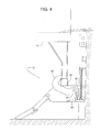
Figure 4 is a side view similar toFigure 1 but showing the example barrier at a first blocking position. -
Figure 5 is a top view ofFigure 4 with previously omitted parts now shown. -
Figure 6 is a side view similar toFigure 4 but with arrows showing movement of the RIG and the example barrier. -
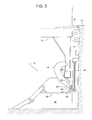
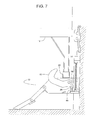
Figure 7 is a side view similar toFigure 4 but showing an example stop member disengaged from a feature of the example barrier. -
Figure 8 is a diagram highlighting an operative edge of an example barrier. -
Figure 9 is a diagram highlighting a back edge of the example barrier shown inFigure 8 . -
Figure 10 is a perspective view of the example barrier shown inFigures 8 and 9 . -
Figure 11 is another perspective view of the example barrier shown inFigures 8 - 10 . -
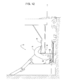
Figure 12 is a side view similar toFigure 4 but showing the example barrier blocking a different RIG. -
Figure 13 is a side view similar toFigure 12 but showing the example barrier blocking yet another style of RIG. -
Figure 14 is a side view similar toFigure 7 but showing another example vehicle restraint. -
Figure 15 is a side view similar toFigure 4 but showing the example restraint ofFigure 14 . -
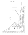
Figure 16 is a side view showing another example of a vehicle restraint with another example barrier in a stored position. -
Figure 17 is a side view similar toFigure 16 but showing the example barrier in one of a plurality of extended blocking positions. -
Figure 18 is a side view similar toFigure 17 but showing the example barrier at a first blocking position. - Some example vehicle restraints disclosed herein include a pivotal barrier for blocking a vehicle's RIG (Rear Impact Guard) near the dock face of a loading dock. Some disclosed examples also include a movable stop that selectively engages a feature or structure on the barrier to limit the extent to which the barrier can withdraw from a plurality of extended blocking positions. To provide the restraint with a compact design; to help shield the stop and associated feature from contamination and impact; and/or to help reduce (e.g., prevent) the stop and feature from presenting an exposed pinch point, the feature is disposed on a back edge of the barrier in some disclosed examples. In some examples, the stop is located underneath the barrier in a generally inaccessible area between two plates of a main barrier-supporting body and is further positioned between a dock-mounted track and a pivotal axis of the barrier.
-
Figures 1 - 7 ,12 and 13 show anexample vehicle restraint 10 that helps reduce (e.g., prevent) a vehicle 12 (e.g., truck, trailer, etc.) from accidentally moving too far forward away from adock face 14 of aloading dock 16 while cargo is being added to and/or removed from thevehicle 12. To limit such forward movement, therestraint 10 includes abarrier 18 for capturing or restraining the vehicle's RIG 20 (Rear Impact Guard), also known as an ICC bar (Interstate Commerce Commission bar). When thevehicle 12 is safely restrained, adock leveler 22 can be deployed to provide a bridge across which forklifts and other material handling equipment can travel to transfer cargo between thevehicle 12 and anelevated platform 24 of thedock 16. The term, "RIG" encompasses the horizontal impact bar plus the framework or structure that connects the bar to the rest of thevehicle 12. - To ensure that the
barrier 18 can positively therestrain RIG 20, thevehicle restraint 10 includes astop 26 movable between a holding position (Figs. 4 ,5 ,6 ,12 and13 ) and a release position (Figs. 1 ,2 ,3 and7 ) for selectively engaging and releasing an engageable feature orstructure 28 of thebarrier 18. When engaged, thestop 26 and thefeature 28 limit the downward movement of thebarrier 18 so that if thevehicle 12 attempts to depart thedock 16 prematurely, wherein theRIG 20 urges thebarrier 18 back down toward its stored position, thefeature 28 abutting thestop 26 holds thebarrier 18 at a height sufficient to still restrain theRIG 20, as shown inFigures 4 ,5 ,12 and13 . - To provide the
vehicle restraint 10 with a compact design; to help shield thestop 26 and thefeature 28 from contamination and impact; and/or to help reduce (e.g., prevent) exposure of the anti-rotation catch mechanism of thestop 26 and thefeature 28 as a pinch point, in some examples, thefeature 28 is disposed on aback edge 30 of thebarrier 18. In some examples, thestop 26 is compactly located underneath thebarrier 18 in a generally inaccessible area between afirst plate 32 and asecond plate 34 of thevehicle restraint 10 and further between a dock-mountedtrack 36 and apivotal axis 38 of thebarrier 18. In some examples, thefeature 28 is an integral protrusion or detent of thebarrier 18 itself, whereby thebarrier 18 and thefeature 28 are a seamless unitary piece for robustness and ease of manufacture. - Although the actual design of the
vehicle restraint 10 may vary, the illustrated example shows thevehicle restraint 10 including thetrack 36 attached to thedock face 14, amain body 39 comprising theplates track 36, and one ormore springs 40 that urge themain body 39 upward, and ashaft 42 pivotally connecting thebarrier 18 to themain body 39 such that thebarrier 18 can rotate about theaxis 38 relative to themain body 39. In the illustrated examples, thevehicle restraint 10 also includes thestop 26, an actuator 44 (e.g., hydraulic cylinder, solenoid, spring, combinations thereof, etc.) for moving thestop 26, abase plate 46 that attaches theactuator 44 to themain body 39, and abackup support member 48 affixed to themain body 39 for reacting or absorbing a substantial force that thefeature 28 may exert against thestop 26. To more clearly illustrate the inner workings of thevehicle restraint 10, theside plate 32 has been omitted inFigures 1 - 4 ,6 ,7 ,12 and 13 . - Some example operations of the vehicle restraint 10 follow the sequence of
Figures 1 ,2 ,3 ,4 ,6 and7 .Figure 1 shows thevehicle 12 backing into thedock 16 and approaching thevehicle restraint 10. At this point in the operation, as shown in the illustrated example ofFigure 1 , thespring 40 holds themain body 39 at a raised preparatory position to receive theRIG 20. In some examples, to allow thevehicle 12 to move theRIG 20 back over the top of thebarrier 18, theactuator 44 holds thestop 26 at its release position, and a drive unit 50 (e.g., hydraulic motor, electric motor, hydraulic cylinder, etc., as shown inFig. 5 ) retracts thebarrier 18 to its stored position relative to themain body 39. In this example, adrive train 52 couples anoutput shaft 54 of amotor 56 to theshaft 42, wherein theshaft 42 is keyed or otherwise affixed to thebarrier 18 so that theshaft 42 and thebarrier 18 rotate as a unit. In some examples, thedrive motor 56, which can rotate in either direction, includes a slip coupling and is able to rotate thebarrier 18 selectively to the barrier's stored position (Figs. 1 and2 ), to a first blocking position (e.g.,Fig. 4 ,5 ,7 ,12 and13 ), and further to a plurality of extended blocking positions (e.g.,Fig. 3 ). - Next, the illustrated example of
Figure 2 shows thevehicle 12 continuing to move back toward thedock face 14. Upon doing so, the RIG 20 forces the vehicle restraint'smain body 39 downward by the RIG 20 sliding along aramp portion 58 of themain body 39. In cases where the RIG 20 is exceptionally low, an articulated lead-inramp extension 60 is used in some examples to guide theRIG 20 onto theramp 58. In this example, a set ofrollers 62 onmain body 39 and extending into thetrack 36 reduces (e.g., minimizes) friction as themain body 39 travels vertically along thetrack 36. As theRIG 20 pushes themain body 39 down, as shown in the illustrated example ofFigure 2 , thebarrier 18 remains in its stored position while thestop 26 is in its release position. - In some examples, after the RIG 20 pushes the
main body 39 down to an operative position (Figs. 3 - 7 ,12 and 13 ), and once thevehicle 12 moves theRIG 20 sufficiently close to thedock face 14, thedrive motor 56 is activated to lift thebarrier 18 to the extended blocking position shown inFigure 3 . In some examples, theactuator 44 subsequently lifts thestop 26 to its holding position. Thebarrier 18 has now captured the RIG 20 within a RIG-receivingarea 64 of thebarrier 18, thereby effectively restraining thevehicle 12 at thedock 16. If, while still being restrained, thevehicle 12 moves forward away from thedock face 14. In some examples, the RIG 20 might exert sufficient force to push thebarrier 18 back down, by overcoming the friction of the drive motor's 56 slip coupling, but only as far as the first blocking position of thebarrier 18 because the barrier's feature 28 encountering thestop 26 provides a solid mechanical engagement that limits further downward movement of thebarrier 18, as shown inFigure 4 . - To release the
vehicle 12 from the condition shown inFigures 4 and5 , in some examples, thevehicle 12 first moves theRIG 20 towards thedock face 14, as indicated by anarrow 66 inFigure 6 , and then themotor 56 momentarily raises thebarrier 18, as indicated by anarrow 68. This action disengages thefeature 28 from thestop 26 to relieve the pressure therebetween, which allows theactuator 44 to retract thestop 26 to its release position. With stop the 26 in its release position, as shown in the illustrated example ofFigure 7 , themotor 56 rotates thebarrier 18 freely back down from its first blocking position (Fig. 7 ) to its stored position (Figs. 1 and2 ). - As mentioned earlier, the
feature 28 being disposed on theback edge 30 of thebarrier 18 offers several benefits including, but not limited to, providing thevehicle restraint 10 with a compact design; shielding thestop 26 and thefeature 28 from contamination and impact; and reducing (e.g., preventing) the working mechanism of thestop 26 and thefeature 28 from presenting an exposed pinch point. The expression, "back edge of a barrier" as used herein is best understood with reference toFigures 8 - 11 . Thebarrier 18, for example, comprises afirst side 70, asecond side 72, aproximal end 74 pivotally coupled to themain body 39, adistal end 76, and an outerperipheral edge 78 lying between thesides outer edge 78 comprises anoperative edge 80 and theback edge 30. Theedges Figures 8 and 9 , respectively, to clearly show where those edges lie. Specifically, aline 84 tangent to theends Figures 8 and 9 , definesend points edges line 84 also helps define the RIG-receivingarea 64 as being the space between theline 84 and theoperative edge 80. With the location of theoperative edge 80 identified, theback edge 30 is the remainder of the outerperipheral edge 78 and lies beyond or outside of the RIG-receivingarea 64. - In some examples, a vehicle's RIG-supporting structure includes some sort of obstruction that prevents the
barrier 18 from extending over the top of theRIG 20. Examples of such obstructions include avertical plate 90 or aninclined plate 92, as shown inFigures 12 and13 , respectively. Nevertheless, in such examples, thebarrier 18 at its first blocking position (Figs. 12 and13 ) can still provide theRIG 20 with ample restraint. - In another example, shown in
Figures 14 and15 , avehicle restraint 10a includes adifferent stop 26a and anengageable feature 28a. In this example,feature 28a is in the form of a plurality of teeth on aback edge 30a of abarrier 18a. Thestop 26a, in this example, includes a mating plurality of teeth on a pivotal or otherwisemovable member 94. In the illustrated example, anactuator 44a pivots themember 94 about apin 96 supported by amain body 39a such that theactuator 44a pivots thestop 26a between a release position (Fig. 14 ) and a holding position (Fig. 15 ). Control of theactuator 44a, in the illustrated example, determines whether the teeth of thestop 26a and thefeature 28a engage or disengage to respectively hold or release thebarrier 18a from its first blocking position shown inFigures 14 and15 . In some examples, disengaging thestop 26a from thefeature 28a allows thebarrier 18a to pivot to a stored position (similar toFig. 1 ) and/or a plurality of extended blocking positions (similar toFig. 3 ). - In another example, shown in
Figures 16 - 18 , avehicle restraint 10b includes astop 26b and anengageable feature 28b (Fig. 17 ). In this example, thefeature 28b is in the form of a detent on aback edge 30b of abarrier 18b. Thestop 26b, in this example, includes aroller 98 on a pivotal or otherwisemovable member 100. In some examples, any actuator is coupled to themember 100 to pivot themember 100 about apin 102 supported by amain body 39b such that themember 100 and thestop 26b pivot between a release position (Fig. 16 ) and a holding position (Fig. 18 ). In some examples, thevehicle restraint 10b also permits separation between thestop 26b and thefeature 28b so that thebarrier 18b can pivot to a plurality of extended blocking positions, such as the extended blocking position shown inFigure 17 . - At least some of the aforementioned examples include one or more features and/or benefits including, but not limited to, the following:
- In some examples, a vehicle restraint to engage a RIG (rear impact guard) of a vehicle at a loading dock including a main body mountable at the loading dock to move vertically relative to the loading dock, where the main body includes a first plate and a second plate that are spaced apart to define a barrier-receiving space therebetween. In some such examples, a barrier may extend into the barrier-receiving space, where the barrier may include a first side, a second side, a proximal end, a distal end, and an outer peripheral edge extending between the first side and the second side, the outer peripheral edge having an operative edge extending between the proximal end and the distal end and a back edge extending between the proximal end and the distal end, and where the proximal end may be pivotally coupled to the main body and interposed between the first plate and the second plate. In some such examples, the distal end may be selectively movable relative to the main body to a first blocking position to block the RIG, a plurality of extended blocking positions beyond the first blocking position, and a stored position to release the RIG, where the distal end relative to the main body is higher in the first blocking position than in the stored position. In some such examples, the first side of the barrier generally facing the first plate of the main body when the distal end is in the stored position and the second side of the barrier generally facing the second plate of the main body when the distal end is in the stored position. In some such examples, the barrier providing a RIG-receiving area defined by the operative edge and an imaginary line lying tangentially to the proximal end and the distal end, where the back edge is disposed outside of the RIG-receiving area. In some such examples, the barrier may encircle an axis about which the barrier pivots relative to the main body, the axis being at a substantially fixed location relative to the main body. In some such examples, an engageable feature may be provided by the back edge of the barrier, and a stop may be coupled to the main body and may be selectively moveable between a release position and a holding position. In some such examples, the stop may engage the engageable feature of the back edge when the distal end is at the first blocking position while the stop is at the holding position, the stop may be spaced apart from the engageable feature when the distal end is at the first blocking position while the stop is at the release position, and the stop may be spaced apart from the engageable feature when the distal end is in the stored position.
- In some examples, the stop may be spaced apart from the engageable feature when the distal end is at one of the plurality of extended blocking positions regardless of whether the stop is at the release position or the holding position.
- In some examples, the engageable feature may be a protrusion extending from the back edge of the barrier.
- In some examples, the engageable feature includes a plurality of teeth disposed on the back edge of the barrier.
- In some examples, the barrier and the engageable feature may be of a unitary piece.
- In some examples, the stop includes a roller.
- In some examples, the stop includes a plurality of teeth.
- In some examples, the stop may be pivotal between the release position and the holding position.
- In some examples, a backup support may be coupled to the main body, the stop being movable relative to the backup support and the stop may be interposed between the backup support and the engageable feature when the distal end of the barrier is in the first blocking position while the stop is in the holding position.
- In some examples, a hydraulic actuator may be coupled to the stop to move the stop between the holding position and the release position.
- In some examples, a track may be mountable to the loading dock to support the main body with the main body being vertically movable along the track.
- In some examples, the track may be closer to the stop than to the axis about which the barrier pivots.
- In some examples, a vehicle restraint may engage a RIG (rear impact guard) of a vehicle at a loading dock a main body to move vertically relative to the loading dock, where the main body has a first plate and a second plate that are spaced apart to define a barrier-receiving space therebetween. In some such examples, a barrier may extend into the barrier-receiving space and having a first side, a second side, a proximal end, a distal end, and an outer peripheral edge extending between the first side and the second side, the outer peripheral edge comprising an operative edge extending between the proximal end and the distal end and a back edge extending between the proximal end and the distal end, where the proximal end may be pivotally coupled to the main body and interposed between the first plate and the second plate. In some such examples, the distal end may be selectively movable relative to the main body to a first blocking position to block the RIG, a plurality of extended blocking positions beyond the first blocking position, and a stored position to release the RIG. In some such examples, the distal end relative to the main body may be higher in the first blocking position than in the stored position, the first side of the barrier generally facing the first plate of the main body when the distal end is in the stored position, the second side of the barrier generally facing the second plate of the main body when the distal end is in the stored position, the barrier providing a RIG-receiving area defined by the operative edge and an imaginary line lying tangent to the proximal end and the distal end, the back edge being disposed outside of the RIG-receiving area, the barrier encircling an axis about which the barrier pivots relative to the main body, and the axis being at a substantially fixed location relative to the main body. In some such examples, an engageable structure may be provided by the back edge of the barrier, where the barrier and the engageable structure may be a unitary piece. In some such examples, a stop may be coupled to the main body and may be selectively moveable between a release position and a holding position, where the stop may engage the engageable structure of the back edge when the distal end is at the first blocking position while the stop is at the holding position, the stop may be spaced apart from the engageable structure when the distal end is at the first blocking position while the stop is at the release position, the stop may be spaced apart from the engageable structure when the distal end is in the stored position, and the stop may be spaced apart from the engageable structure when the distal end is at one of the plurality of extended blocking positions regardless of whether the stop is at the release position or the holding position.
- In some examples, the engageable structure may be a protrusion extending from the back edge of the barrier.
- In some examples, the engageable structure may include a first plurality of teeth disposed on the back edge of the barrier, and the stop includes a second plurality of teeth engageable with the first plurality of teeth.
- In some examples, the stop includes a roller.
- In some examples, a backup support may be coupled to the main body, where the stop may be movable relative to the backup support, and where the stop may be interposed between the backup support and the engageable structure when the distal end of the barrier is in the first blocking position while the stop is in the holding position.
- In some examples, a track may be mountable to the loading dock and supporting the main body with the main body being vertically movable along the track, where the track may be closer to the stop than to the axis about which the barrier pivots.
- In some examples, a vehicle restraint may engage a RIG (rear impact guard) of a vehicle at a loading dock, the vehicle restraint including a main body mountable at the loading dock for vertical movement relative thereto a barrier comprising a proximal end, a distal end, an operative edge extending between the proximal end and the distal end along a first portion of an outer peripheral edge of the barrier, and a back edge extending between the proximal end and the distal end along a remaining portion of the outer peripheral edge. In some such examples, the proximal end of the barrier may be pivotally coupled to the main body to enable the barrier to pivot about an axis at a substantially fixed location relative to the main body. In some such examples, the distal end may be selectively movable about the axis to a first blocking position, a plurality of extended blocking positions beyond the first blocking position, and a stored position, where the distal end is higher relative to the main body in the first blocking position than in the stored position. In some such examples, the operative edge of the barrier and a line lying between the proximal end and the distal end of the barrier define an area to receive and block the RIG. In some such examples, an engageable protrusion may extend from the back edge of the barrier, where the barrier and the engageable protrusion may be a unitary piece. In some such examples, a stop may be coupled to the main body and selectively moveable between a release position and a holding position, where the stop may engage the engageable protrusion of the back edge when the distal end is at the first blocking position while the stop is at the holding position, the stop may be spaced apart from the engageable feature when the distal end is at the first blocking position while the stop is at the release position, the stop may be spaced apart from the engageable structure when the distal end is in the stored position, and the stop may be spaced apart from the engageable protrusion when the distal end is at one of the plurality of extended blocking positions regardless of whether the stop is at the release position or the holding position. In some such examples, a hydraulic actuator may be coupled to the stop to move the stop between the holding position and the release position, and a backup support may be coupled to the main body, where the stop may be movable relative to the backup support, and the stop may be interposed between the backup support and the engageable protrusion when the distal end of the barrier is in the first blocking position while the stop is in the holding position
- In some examples, a track may be mountable to the loading dock and supporting the main body with the main body being vertically movable along the track, where the track is closer to the stop than to the axis about which the barrier pivots.
- Although certain example methods, apparatus and/or articles of manufacture have been described herein, the scope of the coverage of this patent is not limited thereto. On the contrary, this patent covers all methods, apparatus and articles of manufacture fairly falling within the scope of the appended claims either literally or under the doctrine of equivalents.
Claims (20)
- A vehicle restraint to engage a RIG (rear impact guard) of a vehicle at a loading dock, the vehicle restraint comprising:a main body mountable at the loading dock to move vertically relative to the loading dock , the main body comprising a first plate and a second plate that are spaced apart to define a barrier-receiving space therebetween;a barrier to extend into the barrier-receiving space, the barrier comprising a first side, a second side, a proximal end, a distal end, and an outer peripheral edge extending between the first side and the second side, the outer peripheral edge comprising an operative edge extending between the proximal end and the distal end and a back edge extending between the proximal end and the distal end, the proximal end being pivotally coupled to the main body and being interposed between the first plate and the second plate, the distal end being selectively movable relative to the main body to a first blocking position to block the RIG, a plurality of extended blocking positions beyond the first blocking position, and a stored position to release the RIG, the distal end relative to the main body being higher in the first blocking position than in the stored position, the first side of the barrier generally facing the first plate of the main body when the distal end is in the stored position, the second side of the barrier generally facing the second plate of the main body when the distal end is in the stored position, the barrier providing a RIG-receiving area defined by the operative edge and an imaginary line lying tangentially to the proximal end and the distal end, the back edge being disposed outside of the RIG-receiving area, the barrier to encircle an axis about which the barrier pivots relative to the main body, the axis being at a substantially fixed location relative to the main body;an engageable feature provided by the back edge of the barrier; anda stop coupled to the main body and being selectively moveable between a release position and a holding position, the stop to engage the engageable feature of the back edge when the distal end is at the first blocking position while the stop is at the holding position, the stop being spaced apart from the engageable feature when the distal end is at the first blocking position while the stop is at the release position, and the stop being spaced apart from the engageable feature when the distal end is in the stored position.
- The vehicle restraint of claim 1, wherein the stop is to be spaced apart from the engageable feature when the distal end is at one of the plurality of extended blocking positions regardless of whether the stop is at the release position or the holding position.
- The vehicle restraint of claim 1, wherein the engageable feature is a protrusion extending from the back edge of the barrier.
- The vehicle restraint of claim 1, wherein the engageable feature includes a plurality of teeth disposed on the back edge of the barrier.
- The vehicle restraint of claim 1, wherein the barrier and the engageable feature are of a unitary piece.
- The vehicle restraint of claim 1, wherein the stop includes a roller.
- The vehicle restraint of claim 1, wherein the stop includes a plurality of teeth.
- The vehicle restraint of claim 1, wherein the stop is pivotal between the release position and the holding position.
- The vehicle restraint of claim 1, further comprising a backup support coupled to the main body, the stop being movable relative to the backup support, the stop being interposed between the backup support and the engageable feature when the distal end of the barrier is in the first blocking position while the stop is in the holding position.
- The vehicle restraint of claim 1, further comprising a hydraulic actuator coupled to the stop to move the stop between the holding position and the release position.
- The vehicle restraint of claim 1, further comprising a track mountable to the loading dock to support the main body with the main body being vertically movable along the track.
- The vehicle restraint of claim 11, wherein the track is closer to the stop than to the axis about which the barrier pivots.
- A vehicle restraint to engage a RIG (rear impact guard) of a vehicle at a loading dock, the vehicle restraint comprising:a main body to move vertically relative to the loading dock, the main body comprising a first plate and a second plate that are spaced apart to define a barrier-receiving space therebetween;a barrier extending into the barrier-receiving space and comprising a first side, a second side, a proximal end, a distal end, and an outer peripheral edge extending between the first side and the second side, the outer peripheral edge comprising an operative edge extending between the proximal end and the distal end and a back edge extending between the proximal end and the distal end, the proximal end being pivotally coupled to the main body and being interposed between the first plate and the second plate, the distal end being selectively movable relative to the main body to a first blocking position to block the RIG, a plurality of extended blocking positions beyond the first blocking position, and a stored position to release the RIG, the distal end relative to the main body being higher in the first blocking position than in the stored position, the first side of the barrier generally facing the first plate of the main body when the distal end is in the stored position, the second side of the barrier generally facing the second plate of the main body when the distal end is in the stored position, the barrier providing a RIG-receiving area defined by the operative edge and an imaginary line lying tangent to the proximal end and the distal end, the back edge being disposed outside of the RIG-receiving area, the barrier encircling an axis about which the barrier pivots relative to the main body, the axis being at a substantially fixed location relative to the main body;an engageable structure provided by the back edge of the barrier, the barrier and the engageable structure being a unitary piece; anda stop coupled to the main body and being selectively moveable between a release position and a holding position, the stop to engage the engageable structure of the back edge when the distal end is at the first blocking position while the stop is at the holding position, the stop being spaced apart from the engageable structure when the distal end is at the first blocking position while the stop is at the release position, the stop being spaced apart from the engageable structure when the distal end is in the stored position, and, the stop being spaced apart from the engageable structure when the distal end is at one of the plurality of extended blocking positions regardless of whether the stop is at the release position or the holding position.
- The vehicle restraint of claim 13, wherein the engageable structure is a protrusion extending from the back edge of the barrier.
- The vehicle restraint of claim 13, wherein the engageable structure includes a first plurality of teeth disposed on the back edge of the barrier, and the stop includes a second plurality of teeth engageable with the first plurality of teeth.
- The vehicle restraint of claim 13, wherein the stop includes a roller.
- The vehicle restraint of claim 13, further comprising a backup support coupled to the main body, the stop being movable relative to the backup support, the stop being interposed between the backup support and the engageable structure when the distal end of the barrier is in the first blocking position while the stop is in the holding position.
- The vehicle restraint of claim 13, further comprising a track mountable to the loading dock and supporting the main body with the main body being vertically movable along the track, the track being closer to the stop than to the axis about which the barrier pivots.
- A vehicle restraint to engage a RIG (rear impact guard) of a vehicle at a loading dock, the vehicle restraint comprising:a main body mountable at the loading dock for vertical movement relative thereto a barrier comprising a proximal end, a distal end, an operative edge extending between the proximal end and the distal end along a first portion of an outer peripheral edge of the barrier, and a back edge extending between the proximal end and the distal end along a remaining portion of the outer peripheral edge, the proximal end of the barrier pivotally coupled to the main body to enable the barrier to pivot about an axis at a substantially fixed location relative to the main body, the distal end being selectively movable about the axis to a first blocking position, a plurality of extended blocking positions beyond the first blocking position, and a stored position, the distal end being higher relative to the main body in the first blocking position than in the stored position, the operative edge of the barrier and a line lying between the proximal end and the distal end of the barrier defining an area to receive and block the RIG;an engageable protrusion extending from the back edge of the barrier, the barrier and the engageable protrusion being a unitary piece;a stop coupled to the main body and being selectively moveable between a release position and a holding position, the stop to engage the engageable protrusion of the back edge when the distal end is at the first blocking position while the stop is at the holding position, the stop being spaced apart from the engageable feature when the distal end is at the first blocking position while the stop is at the release position, the stop being spaced apart from the engageable structure when the distal end is in the stored position, and, the stop being spaced apart from the engageable protrusion when the distal end is at one of the plurality of extended blocking positions regardless of whether the stop is at the release position or the holding position;a hydraulic actuator to be coupled to the stop to move the stop between the holding position and the release position; anda backup support coupled to the main body, the stop being movable relative to the backup support, the stop being interposed between the backup support and the engageable protrusion when the distal end of the barrier is in the first blocking position while the stop is in the holding position.
- The vehicle restraint of claim 19, further comprising a track mountable to the loading dock and supporting the main body with the main body being vertically movable along the track, the track to be closer to the stop than to the axis about which the barrier pivots.
Applications Claiming Priority (1)
| Application Number | Priority Date | Filing Date | Title |
|---|---|---|---|
| US14/167,721 US9586771B2 (en) | 2014-01-29 | 2014-01-29 | Vehicle restraints with underside catches |
Publications (1)
| Publication Number | Publication Date |
|---|---|
| EP2902347A1 true EP2902347A1 (en) | 2015-08-05 |
Family
ID=52394882
Family Applications (1)
| Application Number | Title | Priority Date | Filing Date |
|---|---|---|---|
| EP15000161.8A Withdrawn EP2902347A1 (en) | 2014-01-29 | 2015-01-21 | Vehicle restraints with underside catches |
Country Status (5)
| Country | Link |
|---|---|
| US (1) | US9586771B2 (en) |
| EP (1) | EP2902347A1 (en) |
| AU (1) | AU2015200158B2 (en) |
| CA (1) | CA2877984C (en) |
| MX (1) | MX359899B (en) |
Cited By (4)
| Publication number | Priority date | Publication date | Assignee | Title |
|---|---|---|---|---|
| WO2019168788A3 (en) * | 2018-02-27 | 2019-10-10 | Rite-Hite Holding Corporation | Vehicle restraints with a barrier having rotational and translational motion |
| US10745220B2 (en) | 2017-06-28 | 2020-08-18 | Systems, LLC | Vehicle Restraint System |
| US10781062B2 (en) | 2015-11-24 | 2020-09-22 | Systems, LLC | Vehicle restraint system |
| US10906759B2 (en) | 2017-06-28 | 2021-02-02 | Systems, LLC | Loading dock vehicle restraint system |
Families Citing this family (7)
| Publication number | Priority date | Publication date | Assignee | Title |
|---|---|---|---|---|
| US9227799B2 (en) | 2012-08-30 | 2016-01-05 | Rite-Hite Holding Corporation | Vehicle restraints with anti-rotation features |
| US9174811B2 (en) | 2012-09-05 | 2015-11-03 | Rite-Hite Holding Corporation | Vehicle restraints with rotating and translating barriers |
| US9272854B2 (en) | 2014-02-06 | 2016-03-01 | Rite-Hite Holding Corporation | Vehicle restraints with activated catches |
| US10569978B2 (en) | 2018-04-27 | 2020-02-25 | Nordock, Inc. | Trailer restraint with auxiliary securing/locking mechanism |
| US11618642B2 (en) * | 2020-08-20 | 2023-04-04 | Assa Abloy Entrance Systems Ab | Vehicle restraint systems and methods |
| US12297062B1 (en) | 2020-09-21 | 2025-05-13 | The Chamberlain Group Llc. | System and method for restraining a vehicle proximate a loading dock |
| DE102021000494B3 (en) * | 2021-02-02 | 2022-03-31 | Sew-Eurodrive Gmbh & Co Kg | Locking device and driverless transport vehicle |
Citations (4)
| Publication number | Priority date | Publication date | Assignee | Title |
|---|---|---|---|---|
| US5071306A (en) * | 1988-08-16 | 1991-12-10 | Serco Corporation | Vehicle restraint |
| US5203663A (en) * | 1991-05-23 | 1993-04-20 | Dock Leveler Manufacturing, Inc. | Vehicle restraining mechanism |
| US5882167A (en) * | 1997-04-23 | 1999-03-16 | Rite-Hite Holding Corporation | Locking mechanism for a vehicle restraint |
| US20130017044A1 (en) * | 2011-07-13 | 2013-01-17 | Andrew Brooks | Vehicle restraints with stop mechanisms |
Family Cites Families (43)
| Publication number | Priority date | Publication date | Assignee | Title |
|---|---|---|---|---|
| GB701214A (en) | 1950-11-06 | 1953-12-23 | Frank Bernard Harley | Improvements relating to releasable fastenings |
| US4208161A (en) | 1978-05-30 | 1980-06-17 | Rite-Hite Corporation | Device for releasably securing a vehicle to an adjacent support |
| USRE33242E (en) | 1978-05-30 | 1990-06-26 | Abon Corporation | Device for releasably securing a vehicle to an adjacent support |
| US4267748A (en) | 1978-10-02 | 1981-05-19 | Rite Hite Corporation | Releasable lock mechanism |
| US4282621A (en) | 1978-12-11 | 1981-08-11 | Rite-Hite Corporation | Releasable locking device |
| US4373847A (en) | 1981-05-04 | 1983-02-15 | Rite-Hite Corporation | Releasable locking device |
| US4472099A (en) | 1981-06-29 | 1984-09-18 | Rite-Hite Corporation | Releasable locking device |
| US4379354A (en) | 1981-08-05 | 1983-04-12 | Rite-Hite Corporation | Releasable locking device |
| US4605353A (en) | 1983-08-24 | 1986-08-12 | Rite-Hite Corporation | Vehicle restraint |
| US4560315A (en) | 1984-07-11 | 1985-12-24 | Rite-Hite Corporation | Vehicle restraint |
| US4648781A (en) | 1985-05-29 | 1987-03-10 | Tomar Electronics, Inc. | Automatic control system for a releasable vehicle locking device |
| US4674941A (en) | 1985-11-20 | 1987-06-23 | Kelley Company Inc. | Vehicle restraint using a parallelogram linkage |
| US4759678A (en) | 1986-09-08 | 1988-07-26 | Kelley Company Inc. | Vehicle restraint utilizing a fluid cylinder |
| US4861217A (en) | 1987-02-17 | 1989-08-29 | Kelley Company, Inc. | Vehicle restraint using both linear and pivotal movement |
| US4843373A (en) | 1987-12-10 | 1989-06-27 | Rite-Hite Corporation | Loading dock signal and control system |
| US4988254A (en) | 1988-08-16 | 1991-01-29 | Serco Corporation | Vehicle restraint |
| US4887954A (en) | 1989-03-09 | 1989-12-19 | Air-Lec Industries, Inc. | Vehicle restraint |
| CA2140743C (en) | 1990-01-18 | 1999-06-15 | The Serco Corporation | Vehicle restraint |
| US5120181A (en) | 1990-01-18 | 1992-06-09 | The Serco Corporation | Vehicle restraint |
| US5026242A (en) | 1990-02-21 | 1991-06-25 | Serco Corporation | Automatic vehicle restraint |
| US5096359A (en) | 1990-06-20 | 1992-03-17 | The Serco Corporation | Vehicle restraint actuator |
| WO1993003989A1 (en) | 1991-08-13 | 1993-03-04 | Rite-Hite Corporation | A releasable locking device |
| JP2833679B2 (en) | 1992-09-11 | 1998-12-09 | 澄子 松山 | Hook device for lifting heavy objects |
| US5348437A (en) | 1993-05-17 | 1994-09-20 | Overhead Door Corporation | Vehicle restraining apparatus |
| US5505575A (en) | 1994-09-07 | 1996-04-09 | United Dominion Ind., Inc. | Pit mounted retractable vehicle restraint |
| US6139242A (en) | 1997-04-16 | 2000-10-31 | United Dominion Industries, Inc. | Vehicle restraint with security device |
| US6190109B1 (en) * | 1998-06-04 | 2001-02-20 | Rite-Hite Holding Company | Restraining member with recessed shank for a vehicle restraint |
| US6106212A (en) | 1998-10-26 | 2000-08-22 | Rite-Hite Holding Corporation | Power-up vehicle restraint |
| US6162005A (en) | 1999-08-31 | 2000-12-19 | Kelley Company, Inc. | Vehicle restraint with powered latching member |
| US6488464B1 (en) * | 2000-04-26 | 2002-12-03 | Rite Hite Holding Corporation | Vehicle restraint with vertical float |
| US20040042882A1 (en) | 2002-09-04 | 2004-03-04 | Kelley Company, Inc. | Hidden hook vehicle restraint with tab |
| US20050196255A1 (en) * | 2003-12-22 | 2005-09-08 | Matt Sveum | Yieldable brace for a vehicle at a loading dock |
| US7841823B2 (en) * | 2003-12-22 | 2010-11-30 | Rite-Hite Holding Corporation | Brace system and method for a vehicle at a loading dock |
| US20060045678A1 (en) | 2004-08-11 | 2006-03-02 | Jonathan Andersen | Hydraulic vehicle restraint providing horizontal and vertical spring float with a mechanical hard travel limit |
| US7384229B2 (en) * | 2005-01-07 | 2008-06-10 | Denis Gleason | Loading dock vehicle restraint |
| US20080095598A1 (en) | 2006-10-19 | 2008-04-24 | Rite-Hite Holding Corporation | Vehicle restraint with bi-directional sensor |
| CA2699135C (en) | 2009-04-17 | 2014-09-23 | Blue Giant Equipment Corporation | Vehicle restraint system |
| US8596949B2 (en) | 2009-12-29 | 2013-12-03 | Nordock, Inc. | Constant torque vehicle restraint |
| US9096397B2 (en) * | 2010-03-31 | 2015-08-04 | Rite-Hite Holding Corporation | Downwardly insertable vehicle restraints |
| US8678736B2 (en) | 2010-04-01 | 2014-03-25 | Rite-Hite Holding Corporation | Vehicle braces having a track-clamping mechanism |
| US9227799B2 (en) | 2012-08-30 | 2016-01-05 | Rite-Hite Holding Corporation | Vehicle restraints with anti-rotation features |
| US9174811B2 (en) * | 2012-09-05 | 2015-11-03 | Rite-Hite Holding Corporation | Vehicle restraints with rotating and translating barriers |
| US9272854B2 (en) * | 2014-02-06 | 2016-03-01 | Rite-Hite Holding Corporation | Vehicle restraints with activated catches |
-
2014
- 2014-01-29 US US14/167,721 patent/US9586771B2/en active Active
-
2015
- 2015-01-14 AU AU2015200158A patent/AU2015200158B2/en active Active
- 2015-01-15 CA CA2877984A patent/CA2877984C/en active Active
- 2015-01-21 EP EP15000161.8A patent/EP2902347A1/en not_active Withdrawn
- 2015-01-21 MX MX2015000940A patent/MX359899B/en active IP Right Grant
Patent Citations (4)
| Publication number | Priority date | Publication date | Assignee | Title |
|---|---|---|---|---|
| US5071306A (en) * | 1988-08-16 | 1991-12-10 | Serco Corporation | Vehicle restraint |
| US5203663A (en) * | 1991-05-23 | 1993-04-20 | Dock Leveler Manufacturing, Inc. | Vehicle restraining mechanism |
| US5882167A (en) * | 1997-04-23 | 1999-03-16 | Rite-Hite Holding Corporation | Locking mechanism for a vehicle restraint |
| US20130017044A1 (en) * | 2011-07-13 | 2013-01-17 | Andrew Brooks | Vehicle restraints with stop mechanisms |
Cited By (6)
| Publication number | Priority date | Publication date | Assignee | Title |
|---|---|---|---|---|
| US10781062B2 (en) | 2015-11-24 | 2020-09-22 | Systems, LLC | Vehicle restraint system |
| US11465865B2 (en) | 2015-11-24 | 2022-10-11 | Systems, LLC | Vehicle restraint system |
| US10745220B2 (en) | 2017-06-28 | 2020-08-18 | Systems, LLC | Vehicle Restraint System |
| US10906759B2 (en) | 2017-06-28 | 2021-02-02 | Systems, LLC | Loading dock vehicle restraint system |
| WO2019168788A3 (en) * | 2018-02-27 | 2019-10-10 | Rite-Hite Holding Corporation | Vehicle restraints with a barrier having rotational and translational motion |
| US10589944B2 (en) | 2018-02-27 | 2020-03-17 | Rite-Hite Holding Corporation | Vehicle restraints with a barrier having rotational and translational motion |
Also Published As
| Publication number | Publication date |
|---|---|
| US20150210487A1 (en) | 2015-07-30 |
| AU2015200158B2 (en) | 2016-02-25 |
| US9586771B2 (en) | 2017-03-07 |
| AU2015200158A1 (en) | 2015-08-13 |
| CA2877984C (en) | 2017-05-09 |
| CA2877984A1 (en) | 2015-07-29 |
| MX2015000940A (en) | 2015-07-28 |
| MX359899B (en) | 2018-10-15 |
Similar Documents
| Publication | Publication Date | Title |
|---|---|---|
| AU2015200158B2 (en) | Vehicle restraints with underside catches | |
| US9150367B2 (en) | Vehicle restraints with stop mechanisms | |
| US9227799B2 (en) | Vehicle restraints with anti-rotation features | |
| US9174811B2 (en) | Vehicle restraints with rotating and translating barriers | |
| US9272854B2 (en) | Vehicle restraints with activated catches | |
| EP2660170B1 (en) | Safety barrier systems for loading docks | |
| US8303235B2 (en) | Flush-mounted vehicle restraints | |
| EP2552809B1 (en) | Latching mechanisms for removable chocks | |
| CA2348289C (en) | Power-up vehicle restraint | |
| US9096397B2 (en) | Downwardly insertable vehicle restraints | |
| CN112203959A (en) | Vehicle restraint with barrier having rotational and translational movement | |
| US9694996B2 (en) | Dock leveler safety supports and related methods |
Legal Events
| Date | Code | Title | Description |
|---|---|---|---|
| PUAI | Public reference made under article 153(3) epc to a published international application that has entered the european phase |
Free format text: ORIGINAL CODE: 0009012 |
|
| 17P | Request for examination filed |
Effective date: 20150121 |
|
| AK | Designated contracting states |
Kind code of ref document: A1 Designated state(s): AL AT BE BG CH CY CZ DE DK EE ES FI FR GB GR HR HU IE IS IT LI LT LU LV MC MK MT NL NO PL PT RO RS SE SI SK SM TR |
|
| AX | Request for extension of the european patent |
Extension state: BA ME |
|
| 17P | Request for examination filed |
Effective date: 20160128 |
|
| RBV | Designated contracting states (corrected) |
Designated state(s): AL AT BE BG CH CY CZ DE DK EE ES FI FR GB GR HR HU IE IS IT LI LT LU LV MC MK MT NL NO PL PT RO RS SE SI SK SM TR |
|
| 17Q | First examination report despatched |
Effective date: 20160616 |
|
| STAA | Information on the status of an ep patent application or granted ep patent |
Free format text: STATUS: THE APPLICATION IS DEEMED TO BE WITHDRAWN |
|
| 18D | Application deemed to be withdrawn |
Effective date: 20161027 |