EP2902313A1 - Outer fuel tank access cover, wing and aircraft comprising such a cover - Google Patents
Outer fuel tank access cover, wing and aircraft comprising such a cover Download PDFInfo
- Publication number
- EP2902313A1 EP2902313A1 EP15156088.5A EP15156088A EP2902313A1 EP 2902313 A1 EP2902313 A1 EP 2902313A1 EP 15156088 A EP15156088 A EP 15156088A EP 2902313 A1 EP2902313 A1 EP 2902313A1
- Authority
- EP
- European Patent Office
- Prior art keywords
- ftac
- aircraft
- wing
- outer ftac
- fuel tank
- Prior art date
- Legal status (The legal status is an assumption and is not a legal conclusion. Google has not performed a legal analysis and makes no representation as to the accuracy of the status listed.)
- Granted
Links
- 239000002828 fuel tank Substances 0.000 title claims description 19
- 239000000463 material Substances 0.000 claims description 23
- 238000010521 absorption reaction Methods 0.000 claims description 15
- 239000004411 aluminium Substances 0.000 claims description 11
- 229910052782 aluminium Inorganic materials 0.000 claims description 11
- XAGFODPZIPBFFR-UHFFFAOYSA-N aluminium Chemical compound [Al] XAGFODPZIPBFFR-UHFFFAOYSA-N 0.000 claims description 11
- 239000006260 foam Substances 0.000 claims description 10
- 230000003116 impacting effect Effects 0.000 claims description 5
- 239000011800 void material Substances 0.000 claims description 4
- 239000000446 fuel Substances 0.000 abstract description 6
- 239000003351 stiffener Substances 0.000 description 10
- 238000007789 sealing Methods 0.000 description 8
- 238000013459 approach Methods 0.000 description 4
- 239000012634 fragment Substances 0.000 description 4
- 229910052751 metal Inorganic materials 0.000 description 2
- 239000002184 metal Substances 0.000 description 2
- 238000000034 method Methods 0.000 description 2
- 239000004033 plastic Substances 0.000 description 2
- 229920003023 plastic Polymers 0.000 description 2
- 229920002430 Fibre-reinforced plastic Polymers 0.000 description 1
- 238000005452 bending Methods 0.000 description 1
- 230000000052 comparative effect Effects 0.000 description 1
- 239000002131 composite material Substances 0.000 description 1
- 230000001010 compromised effect Effects 0.000 description 1
- 238000005336 cracking Methods 0.000 description 1
- 230000007423 decrease Effects 0.000 description 1
- 230000001419 dependent effect Effects 0.000 description 1
- 239000012530 fluid Substances 0.000 description 1
- 239000003365 glass fiber Substances 0.000 description 1
- 238000004519 manufacturing process Methods 0.000 description 1
- 230000000630 rising effect Effects 0.000 description 1
- 238000012916 structural analysis Methods 0.000 description 1
- 238000012029 structural testing Methods 0.000 description 1
Images



Classifications
-
- B—PERFORMING OPERATIONS; TRANSPORTING
- B64—AIRCRAFT; AVIATION; COSMONAUTICS
- B64D—EQUIPMENT FOR FITTING IN OR TO AIRCRAFT; FLIGHT SUITS; PARACHUTES; ARRANGEMENT OR MOUNTING OF POWER PLANTS OR PROPULSION TRANSMISSIONS IN AIRCRAFT
- B64D37/00—Arrangements in connection with fuel supply for power plant
- B64D37/02—Tanks
- B64D37/06—Constructional adaptations thereof
-
- B—PERFORMING OPERATIONS; TRANSPORTING
- B64—AIRCRAFT; AVIATION; COSMONAUTICS
- B64C—AEROPLANES; HELICOPTERS
- B64C1/00—Fuselages; Constructional features common to fuselages, wings, stabilising surfaces or the like
- B64C1/14—Windows; Doors; Hatch covers or access panels; Surrounding frame structures; Canopies; Windscreens accessories therefor, e.g. pressure sensors, water deflectors, hinges, seals, handles, latches, windscreen wipers
- B64C1/1407—Doors; surrounding frames
- B64C1/1446—Inspection hatches
-
- B—PERFORMING OPERATIONS; TRANSPORTING
- B64—AIRCRAFT; AVIATION; COSMONAUTICS
- B64C—AEROPLANES; HELICOPTERS
- B64C3/00—Wings
- B64C3/34—Tanks constructed integrally with wings, e.g. for fuel or water
Definitions
- the present invention describes an outer fuel access tank cover (FTAC) of an aircraft, a wing comprising such outer FTAC of an aircraft and an aircraft.
- the invention belongs to the field of designing auxiliary pieces in the wings of aircraft to control the risk of impact against an inner FTAC when an impact occurs against the outer FTAC. This impact can be caused by a tire.
- Manholes in an aircraft provide access to the fuel tank.
- Manholes comprise an inner fuel tank access cover (inner FTAC), an outer FTAC and a void area between the two covers.
- Fuel Tank Access Covers (FTACs) are mechanically fastened, with fasteners, such as bolts, and clamped against the aircraft wing skin to provide fuel tank access sealing.
- FTAC are designed to meet a wide array of requirements, some of them are: no fuel leaks, fire resistance, resistance to a tire impact, resistance to impacts resulting from an UERF (Uncontained Engine Rotor Failure), EMH/lightning strike, seal friction, and wing bending.
- the current design approach to address the resistance of the structure to an impact is to have heavy and stiff outer FTACs along with large diameter bolts to absorb the impact energy so that it is not transmitted to the inner FTAC and the sealing integrity of the structure is not compromised
- the present invention provides a solution for the aforementioned problems, by providing an outer FTAC according to claim 1, a wing of an aircraft according to claim 14 and an aircraft according to claim 15.
- an outer FTAC according to claim 1 a wing of an aircraft according to claim 14 and an aircraft according to claim 15.
- preferred embodiments of the invention are defined.
- an outer fuel tank access cover (FTAC) of an aircraft comprising,
- the absorption of the impact energy is particularly carried out by plastic deformation of the outer FTAC provided by the invention.
- the present invention approaches the technical problems described by providing an outer FTAC that intends to improve its sealing performance after an impact and is lighter with respect to current designs.
- this approach reduces the energy transferred to the inner FTAC cover and surrounding wing.
- the absorption of impact energy is achieved by converting the kinetic energy of the impacting fragment to work energy and heat by means of a plastic deformation of certain parts of the FTAC described.
- the advantage of this solution over current designs is that the impact energy is mostly absorbed by the outer FTAC comprising at least one layer of a rigid material in the outer FTAC and at least one piece made of a low density material, thereby minimizing the damage to the support structure, which ensures that sealing performance around the outer FTAC is fulfilled.
- the piece made of a low density material is sandwiched between two layers of a rigid material, for absorbing the main percentage of impact.
- the two layers are aluminium layers and the piece made of a low density material is made of foam.
- a second aspect of the invention presents a wing of an aircraft.
- a last aspect of the invention presents an aircraft comprising a wing according to the second aspect of the invention.
- FIG. 1A An embodiment of an aircraft is represented in figure 1A and its left wing is shown in figure 1B where the locations where the FTACs ( fig. 1C ) are located are shown.
- figure 1D a sectional view of the inner area of the wing wherein the fuel tank (1) is located is represented.
- figures 1D and 1E the relative position of the FTACs to the fuel tank (1) is shown.
- the inner FTAC (3) is in the fuel tank (1) and it is sealed with fuel seals (17) to the lower wing skin (16).
- the outer FTAC (4) is fixed to the lower wing skin (16) by means of a plurality of mounting holes peripherally distributed.
- the fixing means (18), or fasteners, in an embodiment of the invention, are bolts.
- the outer FTAC (4) comprises energy-absorption means which are at least one frangible line (5) located on the inner surface (4.1) of the outer FTAC (4) and calibrated for being ruptured once a predetermined level of energy due to an impact is reached on the inner surface (4.1) of the outer FTAC (4).
- the frangible line is, in one embodiment of the invention, a v-shaped groove scratched on the inner surface (4.1) of the outer FTAC (4), as it can be seen on figure 2 .
- the outer FTAC (4) is characterized in that the frangible line (5) is zigzag shaped.
- the zigzag shape changes the load direction abruptly and creates stress risers aiding in the cracking process.
- the outer FTAC (4) is characterized in that the frangible line (5) defines a closed region (6) within the inner surface (4.1) of the outer FTAC (4).
- This frangible line (5) defining a closed region (6) advantageously creates a high stress riser that crack upon an impact event and, once the cracks propagate, the outer FTAC (4) plasticly deforms and therefore absorbs the impact energy.
- deformable or crumble zones are created on the outer FTAC (4) so that it yields and plastically deforms. These deformation zones are created by the frangible line (5) and it is designed to break at certain energy ranges so that the outer FTAC (4) deforms and breaks in a controlled manner. The majority of the energy is absorbed by the outer FTAC (4) and advantageously it maintains sealing integrity of inner sealing of the outer FTAC (4).
- the solution also reduces the amplitude of the propagation impact wave that is transferred to the inner FTAC (3), so that sealing integrity is fulfilled.
- the outer FTAC (4) is characterized in that it comprises at least an extra frangible line (7).
- the at least an extra frangible line (7) is, in one embodiment, inside the closed region (6).
- the outer FTAC (4) is characterized in that the closed region (6) is ellipse-shaped and zigzagged, and the at least one extra frangible line (7) is zigzagged as it can be seen in figure 3A, 3B, 3C .
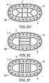
- the outer FTAC (4) is characterized in that the closed region (6) is ellipse-shaped and stitched, and the at least one extra frangible line (7) is stitched as it can be seen in figure 3D, 3E, 3F .
- the stitched feature of the frangible line must be understood as a succession of notches or small weakened areas having less thickness than the one of the outer FTAC (4).
- the outer FTAC (4) is characterized in that it comprises a stiffener ring means (8) on the inner surface (4.1).
- a stiffener ring means (8) on the inner surface (4.1).
- the outer FTAC (4) is characterized in that the stiffener means (8) are a stiffener ring (8) surrounding all the frangible lines (5, 7) on the inner surface (4.1).
- the stiffener ring (8) is part of the inner surface (4.1) of the outer FTAC (4) located in the interior perimeter defined by the line of bolts (18).
- this stiffener ring (8) acts as a rip stop so the cracks do not propagate to the fasteners or bolts.
- the fuel sealing integrity is maintained since the clamping force between the inner FTAC (3) and the outer FTAC (4) is maintained.
- the outer FTAC (4) is made of metal.
- the outer FTAC (4) is made of composite.
- the outer FTAC (4) comprises absorption means which are at least one layer (10, 11) of a rigid material.
- the absorption means are the outer FTAC (4) and it comprises at least one layer (10, 11) of a rigid material.
- the absorption means are the outer FTAC (4) and the absorption means comprise a piece (9) made of a low density material forming the outer FTAC (4).
- the absorption means are the outer FTAC (4), and comprise a piece (9) made of low density material sandwiched between two layers (10, 11) of a rigid material, as shown in figure 4.
- Figure 4 even not being scaled, represents an outer FTAC (4) made of the two layers (10, 11) of a rigid material with a piece (9) of a low density material.
- the outer FTAC (4) adapted for being fixed with the bolts (18) into the wing skin (16) in the aircraft.
- the outermost layer (11) receives the impact
- the piece (9) of a low density material absorbs the main percentage of the impact
- the inner layer (10) provides rigidity to the whole structure.
- the outer FTAC (4) is characterized in that the low density material is foam.
- the outer FTAC (4) is characterized in that the two layers (10, 11) are aluminium layers, and the piece (9) is made of foam and sandwiched between the two layers (10, 11) of aluminium, as it can be seen in figure 4 .
- the foam is Rohacell ® .
- this embodiment yields weight saving opportunities.
- the outer FTAC (4) is characterized in that the two layers (10, 11) are made of glass fibre reinforced plastic (GFRP).
- GFRP glass fibre reinforced plastic
- the solution having the two layers (10, 11) either made of aluminium or GFRP comprises the following advantages:
- the solutions reduce the impact energy transferred to the outer FTAC (4) and surrounding wing skin (16).
- the reduction of impact energy is achieved by converting the kinetic energy of the impacting fragment, for instance a tire fragment, into work-energy and heat by plastically deforming the outer FTAC (4).
- an outer FTAC (4) is represented comprising a foam piece (9) between two layers (10, 11) of aluminium, the upper or inner layer (10) of aluminium being 2 mm thick and the lower or outermost layer (11) being 1mm thick.
Landscapes
- Engineering & Computer Science (AREA)
- Aviation & Aerospace Engineering (AREA)
- Mechanical Engineering (AREA)
- Laminated Bodies (AREA)
- Vibration Dampers (AREA)
- Tires In General (AREA)
Abstract
Description
- The present invention describes an outer fuel access tank cover (FTAC) of an aircraft, a wing comprising such outer FTAC of an aircraft and an aircraft. The invention belongs to the field of designing auxiliary pieces in the wings of aircraft to control the risk of impact against an inner FTAC when an impact occurs against the outer FTAC. This impact can be caused by a tire.
- Manholes in an aircraft provide access to the fuel tank. Manholes comprise an inner fuel tank access cover (inner FTAC), an outer FTAC and a void area between the two covers. Fuel Tank Access Covers (FTACs) are mechanically fastened, with fasteners, such as bolts, and clamped against the aircraft wing skin to provide fuel tank access sealing. FTAC are designed to meet a wide array of requirements, some of them are: no fuel leaks, fire resistance, resistance to a tire impact, resistance to impacts resulting from an UERF (Uncontained Engine Rotor Failure), EMH/lightning strike, seal friction, and wing bending. The current design approach to address the resistance of the structure to an impact, for example, a tire impact, is to have heavy and stiff outer FTACs along with large diameter bolts to absorb the impact energy so that it is not transmitted to the inner FTAC and the sealing integrity of the structure is not compromised
- The technical problem encountered in current solutions is that FTACs are too heavy. Another problem is the surrounding mounting structure is damaged which could create major repair issues.
- Therefore, there is a need to find a solution for FTACs which
- decreases weight in an aircraft and which
- prevents the impact energy of an impact on the outer FTAC (4) to reach an inner FTAC (3) in an aircraft.
- prevent damage to the manhole mounting structure.
- The mentioned prior art approach is seen in the patent
US 4 291 816 A wherein a fluid tight closure for an aperture, adapted to form a fuel tank access door for an aircraft, and providing fail-safe features and resistance to lightning strikes is described - Other patent documents describing different solutions in aircrafts approaching absorption of impact energy and or designing FTAC and fuel tank access covers accomplishing the required characteristics taken into account in the state of the art are:
EP 1 628 877 B1US 5,316,167 ,US 2001/0010345 ,US 2007/0207421 ,US 2012/0217347 ,US 4,291,816 . - The present invention provides a solution for the aforementioned problems, by providing an outer FTAC according to
claim 1, a wing of an aircraft according toclaim 14 and an aircraft according toclaim 15. In dependent claims, preferred embodiments of the invention are defined. - In a first aspect of the invention, it is presented an outer fuel tank access cover (FTAC) of an aircraft comprising,
- an inner surface,
- an outer surface,
- the outer FTAC adapted for being used to cover the outer opening of a void area of a manhole for accessing the interior of a wing of an aircraft wherein the interior of the wing comprises a fuel tank
- adapted for absorbing the impact energy due to an object impacting against the outer FTAC, and comprising
- at least one layer of a rigid material in the outer FTAC and
- at least one piece made of a low density material.
- The absorption of the impact energy is particularly carried out by plastic deformation of the outer FTAC provided by the invention.
- The present invention approaches the technical problems described by providing an outer FTAC that intends to improve its sealing performance after an impact and is lighter with respect to current designs.
- Advantageously, this approach reduces the energy transferred to the inner FTAC cover and surrounding wing. The absorption of impact energy is achieved by converting the kinetic energy of the impacting fragment to work energy and heat by means of a plastic deformation of certain parts of the FTAC described.
- The advantage of this solution over current designs is that the impact energy is mostly absorbed by the outer FTAC comprising at least one layer of a rigid material in the outer FTAC and at least one piece made of a low density material, thereby minimizing the damage to the support structure, which ensures that sealing performance around the outer FTAC is fulfilled.
- In certain embodiments the piece made of a low density material is sandwiched between two layers of a rigid material, for absorbing the main percentage of impact.
- In certain embodiments the two layers are aluminium layers and the piece made of a low density material is made of foam.
- A second aspect of the invention presents a wing of an aircraft.
- A last aspect of the invention presents an aircraft comprising a wing according to the second aspect of the invention.
- All the features described in this specification (including the claims, description and drawings) and/or all the steps of the described method can be combined in any combination, with the exception of combinations of such mutually exclusive features and/or steps.
- These and other characteristics and advantages of the invention will become clearly understood in view of the detailed description of the invention which becomes apparent from a preferred embodiment of the invention, given just as an example and not being limited thereto, with reference to the drawings.
- Figure 1A
- This figure represents an embodiment of an aircraft wherein the left wing is shown in black.
- Figure 1B
- This figure shows the locations of the wing of the aircraft shown in
figure 1A where the FTACs are located. - Figure 1C
- In this figure an embodiment of an outer FTAC according to the state of the art is represented.
- Figure 1D
- In this figure a sectional view of the inner area of the wing wherein the fuel tank (1) is located is represented. Besides, the relative position of the FTACs to the fuel tank (1) is shown. The different embodiments of the invention are located on the outer FTAC.
- Figure 1E
- In this figure a zoomed view of
figure 1D is represented where the inner FTAC (3) and outer FTAC (4) are joined by means of bolts (18) and the inner FTAC (3) is shown to be sealed to the wing skin (16) with fuel seals (17). - Figures 2A, 2B:
- These figures represent two views of an embodiment of the invention where a frangible line (5) is visible on the inner surface (4.1) of an outer FTAC (4). In
figure 2B a particular embodiment is shown wherein the FTAC comprises a rip stop feature (8). - Figures 3A, 3B, 3C, 3D, 3E, 3F:
- Various frangible line (5, 7) patterns are shown in
figures 3A, 3B, 3C ,3D, 3E, 3F . - Figure 4
- In this figure an embodiment of an outer FTAC is represented which comprises a foam core (9) between two layers (10, 11) of aluminium.
- Figure 5
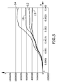
- In this figure a comparative graphic is shown, wherein different levels of energy absorbed per second having different absorption means are represented.
- Once the object of the invention has been outlined, specific non-limitative embodiments are described hereinafter.
- An embodiment of an aircraft is represented in
figure 1A and its left wing is shown infigure 1B where the locations where the FTACs (fig. 1C ) are located are shown. Infigure 1D a sectional view of the inner area of the wing wherein the fuel tank (1) is located is represented. Besides, infigures 1D and 1E the relative position of the FTACs to the fuel tank (1) is shown. The inner FTAC (3) is in the fuel tank (1) and it is sealed with fuel seals (17) to the lower wing skin (16). The outer FTAC (4) is fixed to the lower wing skin (16) by means of a plurality of mounting holes peripherally distributed. The fixing means (18), or fasteners, in an embodiment of the invention, are bolts. - In an embodiment of the invention, the outer FTAC (4) comprises energy-absorption means which are at least one frangible line (5) located on the inner surface (4.1) of the outer FTAC (4) and calibrated for being ruptured once a predetermined level of energy due to an impact is reached on the inner surface (4.1) of the outer FTAC (4). The frangible line is, in one embodiment of the invention, a v-shaped groove scratched on the inner surface (4.1) of the outer FTAC (4), as it can be seen on
figure 2 . - In an embodiment of the invention, the outer FTAC (4) is characterized in that the frangible line (5) is zigzag shaped. Advantageously, the zigzag shape changes the load direction abruptly and creates stress risers aiding in the cracking process.
- In an embodiment of the invention, the outer FTAC (4) is characterized in that the frangible line (5) defines a closed region (6) within the inner surface (4.1) of the outer FTAC (4). This frangible line (5) defining a closed region (6) advantageously creates a high stress riser that crack upon an impact event and, once the cracks propagate, the outer FTAC (4) plasticly deforms and therefore absorbs the impact energy.
- Another advantage provided by the solution proposed is that deformable or crumble zones are created on the outer FTAC (4) so that it yields and plastically deforms. These deformation zones are created by the frangible line (5) and it is designed to break at certain energy ranges so that the outer FTAC (4) deforms and breaks in a controlled manner. The majority of the energy is absorbed by the outer FTAC (4) and advantageously it maintains sealing integrity of inner sealing of the outer FTAC (4). Advantageously, the solution also reduces the amplitude of the propagation impact wave that is transferred to the inner FTAC (3), so that sealing integrity is fulfilled.
- In an embodiment of the invention, the outer FTAC (4) is characterized in that it comprises at least an extra frangible line (7). The at least an extra frangible line (7) is, in one embodiment, inside the closed region (6).
- In an embodiment of the invention, the outer FTAC (4) is characterized in that the closed region (6) is ellipse-shaped and zigzagged, and the at least one extra frangible line (7) is zigzagged as it can be seen in
figure 3A, 3B, 3C . - In an embodiment of the invention, the outer FTAC (4) is characterized in that the closed region (6) is ellipse-shaped and stitched, and the at least one extra frangible line (7) is stitched as it can be seen in
figure 3D, 3E, 3F . - In the context of the present invention, the stitched feature of the frangible line must be understood as a succession of notches or small weakened areas having less thickness than the one of the outer FTAC (4).
- In an embodiment of the invention, the outer FTAC (4) is characterized in that it comprises a stiffener ring means (8) on the inner surface (4.1). Advantageously having a closed region (6) and stiffener ring means (8) makes the crack be contained within the stiffener ring means (8).
- In an embodiment of the invention, the outer FTAC (4) is characterized in that the stiffener means (8) are a stiffener ring (8) surrounding all the frangible lines (5, 7) on the inner surface (4.1). The stiffener ring (8) is part of the inner surface (4.1) of the outer FTAC (4) located in the interior perimeter defined by the line of bolts (18). Advantageously, this stiffener ring (8) acts as a rip stop so the cracks do not propagate to the fasteners or bolts. Advantageously, the fuel sealing integrity is maintained since the clamping force between the inner FTAC (3) and the outer FTAC (4) is maintained.
- In an embodiment of the invention, the outer FTAC (4) is made of metal.
- In an embodiment of the invention, the outer FTAC (4) is made of composite.
- In a further embodiment of the invention the the outer FTAC (4) comprises absorption means which are at least one layer (10, 11) of a rigid material.
- In a further embodiment of the invention the absorption means are the outer FTAC (4) and it comprises at least one layer (10, 11) of a rigid material.
- In an embodiment of the invention the absorption means are the outer FTAC (4) and the absorption means comprise a piece (9) made of a low density material forming the outer FTAC (4).
- In an embodiment of the invention the absorption means are the outer FTAC (4), and comprise a piece (9) made of low density material sandwiched between two layers (10, 11) of a rigid material, as shown in
figure 4. Figure 4 , even not being scaled, represents an outer FTAC (4) made of the two layers (10, 11) of a rigid material with a piece (9) of a low density material. The outer FTAC (4) adapted for being fixed with the bolts (18) into the wing skin (16) in the aircraft. Advantageously, in the event of an impact, the outermost layer (11) receives the impact, the piece (9) of a low density material absorbs the main percentage of the impact, and the inner layer (10) provides rigidity to the whole structure. - In an embodiment of the invention, the outer FTAC (4) is characterized in that the low density material is foam.
- In an embodiment of the invention, the outer FTAC (4) is characterized in that the two layers (10, 11) are aluminium layers, and the piece (9) is made of foam and sandwiched between the two layers (10, 11) of aluminium, as it can be seen in
figure 4 . In one embodiment the foam is Rohacell®. Advantageously this embodiment yields weight saving opportunities. - In an embodiment of the invention, the outer FTAC (4) is characterized in that the two layers (10, 11) are made of glass fibre reinforced plastic (GFRP).
- Advantageously, the solution having the two layers (10, 11) either made of aluminium or GFRP comprises the following advantages:
- no complex manufacturing,
- aerodynamic features, and.
- low weight
- The solutions reduce the impact energy transferred to the outer FTAC (4) and surrounding wing skin (16). The reduction of impact energy is achieved by converting the kinetic energy of the impacting fragment, for instance a tire fragment, into work-energy and heat by plastically deforming the outer FTAC (4).
- A detailed structural analysis and testing have been performed testing the outer FTAC (4) of the invention which received the impact of an aircraft tire fragment. Various frangible lines (5) patterns, some of them shown in
figures 3A, 3B, 3C ,3D, 3E, 3F , have been analysed using structural analysis software to determine the different energy absorption characteristics for each solution. - In
figure 4 an outer FTAC (4) is represented comprising a foam piece (9) between two layers (10, 11) of aluminium, the upper or inner layer (10) of aluminium being 2 mm thick and the lower or outermost layer (11) being 1mm thick. - The embodiment of an outer FTAC (4) comprising a foam core (9) between the two layers of aluminium (10, 11) analytically shows the major absorbed impact energy. In
figure 5 the absorbed impact energy, in joules (axis Y represents Energy in joules) per second (axis X represents time). The legend of such figure is as follows: - (12): Absorbed tire impact energy by an outer FTAC comprising a zigzagged frangible line as shown in
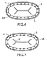
figure 7 . - (13): Absorbed tire impact energy by an outer FTAC (4) comprising a stitched frangible line (5) as shown in
figure 6 . - (14): Absorbed tire impact energy by an outer FTAC (4) comprising a foam piece (9) between two layers (10, 11) of aluminium, as shown in
figure 4 . - (15) Absorbed tire impact energy by an outer FTAC (4) comprising a frangible ellipse and zigzagged line (5) and a straight zigzagged frangible line (7), as shown in
figure 3A . - The rising conclusions are:
- the zigzag pattern provides better results than the stitched pattern,
- the closed ellipse (5) also provides better results than having a single frangible line (7),
- the best performance is provided by a foam piece (9) between two layers (10, 11) of aluminium, as shown in
figure 4 . - Preferred embodiments of the invention are outlined in the following non-limiting numbered clauses:
- 1. Outer fuel tank access cover (FTAC) (4) of an aircraft comprising,
an inner surface (4.1),
an outer surface (4.2),
the outer FTAC adapted for being used to cover the outer opening of a void area (2) of a manhole for accessing the interior of a wing of an aircraft wherein the interior of the wing comprises a fuel tank (1),
characterized in that the outer FTAC comprises absorption means- adapted for absorbing the impact energy due to an object impacting against the outer FTAC (4), and
- comprising
- at least one layer (10, 11) of a rigid material in the outer FTAC (4) and
- at least one piece (9) made of a low density material.
- 2. Outer FTAC (4) according to
clause 1 wherein the absorption means are at least one frangible line (5) located on the inner surface (4.1) of the outer FTAC (4) and calibrated for being ruptured once a predetermined level of energy due to an impact is reached. - 3. Outer FTAC (4) according to
clause 2 wherein the frangible line (5) is zigzag shaped. - 4. Outer FTAC (4) according to
clauses - 5. Outer FTAC (4) according to any of the preceding clauses wherein it comprises at least an extra frangible line (7).
- 6. Outer FTAC (4) according to
clauses - 7. Outer FTAC (4) according to any of the preceding clauses wherein it comprises a stiffener means (8).
- 8. Outer FTAC (4) according to
clause 7 wherein the stiffener means (8) is a stiffener ring (8) surrounding all the frangible lines (5, 7) on the inner surface (4.1) and it is located within the interior perimeter defined by the line of bolts (18). - 9. Outer FTAC (4) according to any of the preceding clauses wherein the outer FTAC (4) is made of metal.
Claims (5)
- Outer fuel tank access cover (FTAC) (4) of an aircraft comprising,
an inner surface (4.1),
an outer surface (4.2),
the outer FTAC adapted for being used to cover the outer opening of a void area (2) of a manhole for accessing the interior of a wing of an aircraft wherein the interior of the wing comprises a fuel tank (1),
characterized in that the outer FTAC comprises absorption means- adapted for absorbing the impact energy due to an object impacting against the outer FTAC (4), and- comprising- at least one layer (10, 11) of a rigid material in the outer FTAC (4) and- at least one piece (9) made of a low density material. - Outer FTAC (4) according to claim 1 characterized in that the piece (9) made of a low density material is sandwiched between two layers (10, 11) of a rigid material.
- Outer FTAC (4) according to claim 2 characterized in that the two layers (10, 11) are aluminium layers and the piece (9) made of a low density material is made of foam.
- Wing of an aircraft comprising at least one fuel tank access comprising an outer FTAC (4) according to any of the preceding claims.
- Aircraft comprising a wing according to claim 4.
Priority Applications (1)
| Application Number | Priority Date | Filing Date | Title |
|---|---|---|---|
| EP15156088.5A EP2902313B1 (en) | 2012-12-21 | 2012-12-21 | Outer fuel tank access cover, wing and aircraft comprising such a cover |
Applications Claiming Priority (2)
| Application Number | Priority Date | Filing Date | Title |
|---|---|---|---|
| EP15156088.5A EP2902313B1 (en) | 2012-12-21 | 2012-12-21 | Outer fuel tank access cover, wing and aircraft comprising such a cover |
| EP12382523.4A EP2746150B1 (en) | 2012-12-21 | 2012-12-21 | Outer fuel tank access cover, wing and aircraft comprising such a cover |
Related Parent Applications (2)
| Application Number | Title | Priority Date | Filing Date |
|---|---|---|---|
| EP12382523.4A Division EP2746150B1 (en) | 2012-12-21 | 2012-12-21 | Outer fuel tank access cover, wing and aircraft comprising such a cover |
| EP12382523.4A Division-Into EP2746150B1 (en) | 2012-12-21 | 2012-12-21 | Outer fuel tank access cover, wing and aircraft comprising such a cover |
Publications (2)
| Publication Number | Publication Date |
|---|---|
| EP2902313A1 true EP2902313A1 (en) | 2015-08-05 |
| EP2902313B1 EP2902313B1 (en) | 2017-05-10 |
Family
ID=47630129
Family Applications (2)
| Application Number | Title | Priority Date | Filing Date |
|---|---|---|---|
| EP12382523.4A Not-in-force EP2746150B1 (en) | 2012-12-21 | 2012-12-21 | Outer fuel tank access cover, wing and aircraft comprising such a cover |
| EP15156088.5A Not-in-force EP2902313B1 (en) | 2012-12-21 | 2012-12-21 | Outer fuel tank access cover, wing and aircraft comprising such a cover |
Family Applications Before (1)
| Application Number | Title | Priority Date | Filing Date |
|---|---|---|---|
| EP12382523.4A Not-in-force EP2746150B1 (en) | 2012-12-21 | 2012-12-21 | Outer fuel tank access cover, wing and aircraft comprising such a cover |
Country Status (3)
| Country | Link |
|---|---|
| US (1) | US20140191085A1 (en) |
| EP (2) | EP2746150B1 (en) |
| CN (1) | CN103879548A (en) |
Cited By (1)
| Publication number | Priority date | Publication date | Assignee | Title |
|---|---|---|---|---|
| DE102022211424B3 (en) | 2022-10-27 | 2024-01-04 | Airbus Defence and Space GmbH | Device for creating a stiffened area on an external structure of an aircraft for the subsequent provision of service access if necessary, and method for producing and using such a service access |
Families Citing this family (3)
| Publication number | Priority date | Publication date | Assignee | Title |
|---|---|---|---|---|
| FR3043062B1 (en) | 2015-10-28 | 2017-11-24 | Aviacomp | ACCESS DOOR TO THE FUEL TANK OR A DRY ZONE OF AN AIRCRAFT |
| FR3043064B1 (en) * | 2015-10-28 | 2017-11-24 | Aviacomp | ACCESS DOOR TO THE FUEL TANK OR A DRY ZONE OF AN AIRCRAFT |
| CN111924113A (en) * | 2020-09-15 | 2020-11-13 | 中国商用飞机有限责任公司北京民用飞机技术研究中心 | An aircraft wing fuel tank cover and the structure of the peripheral area of the cover |
Citations (8)
| Publication number | Priority date | Publication date | Assignee | Title |
|---|---|---|---|---|
| US4291816A (en) | 1980-07-09 | 1981-09-29 | Canadair Limited | Fuel tank access door for aircraft |
| US4530443A (en) * | 1983-11-10 | 1985-07-23 | The Boeing Company | Unitary access panel for aircraft fuel tanks |
| US5316167A (en) | 1992-12-23 | 1994-05-31 | United Technologies Corporation | Pressure resistant fuel tank closure |
| US20010010345A1 (en) | 2000-01-29 | 2001-08-02 | Clifford William Simon | Method of improving the crashworthiness of an aircraft |
| US20070207421A1 (en) | 2006-02-23 | 2007-09-06 | Heeter Russell J | Method and system for electrical bonding of fuel tank penetrations |
| US20090166473A1 (en) * | 2007-12-27 | 2009-07-02 | Airbus Espana, S.L. | Optimized aircraft manhole |
| EP1628877B1 (en) | 2003-05-30 | 2009-09-02 | Politecnico Di Milano | Crashworthiness structure and method |
| US20120217347A1 (en) | 2011-02-24 | 2012-08-30 | Airbus Operations Limited | aircraft fuel tank access cover and an aircraft fuel tank |
Family Cites Families (12)
| Publication number | Priority date | Publication date | Assignee | Title |
|---|---|---|---|---|
| US2200922A (en) * | 1936-04-15 | 1940-05-14 | Specialties Dev Corp | Fuel tank dump valve |
| US2607302A (en) * | 1949-10-26 | 1952-08-19 | Standard Railway Equipment Mfg | Hatch plug |
| US2675252A (en) * | 1950-08-22 | 1954-04-13 | Goodrich Co B F | Tank fitting and method of making same |
| US2635785A (en) * | 1951-10-30 | 1953-04-21 | Rohr Aircraft Corp | Sealed door assembly |
| US3026070A (en) * | 1958-07-07 | 1962-03-20 | Goodyear Tire & Rubber | Fuel tank fitting |
| IL60528A (en) * | 1980-07-09 | 1984-03-30 | Spectronix Ltd | Fire preventing barrier |
| US5087511A (en) * | 1990-08-31 | 1992-02-11 | General Electric Company | Composite element having a variable density core |
| US5368180A (en) * | 1993-10-12 | 1994-11-29 | Bs&B Safety Systems, Inc. | Perforated rupture disk assembly |
| US7226360B2 (en) * | 2001-12-14 | 2007-06-05 | Gkn Driveline North America, Inc. | Grease cap for a constant velocity joint |
| CN2928957Y (en) * | 2006-07-14 | 2007-08-01 | 苏州市广卫特种水泥制品有限公司 | Manhole grate covers and manhole covers with high-strength rib structure |
| CN201390976Y (en) * | 2009-03-23 | 2010-01-27 | 耿靓 | Anti- side tumbling manhole cover component |
| ES2580037T3 (en) * | 2012-05-16 | 2016-08-18 | Airbus Operations, S.L. | External cover for access to fuel tank, wing and aircraft |
-
2012
- 2012-12-21 EP EP12382523.4A patent/EP2746150B1/en not_active Not-in-force
- 2012-12-21 EP EP15156088.5A patent/EP2902313B1/en not_active Not-in-force
-
2013
- 2013-12-20 US US14/136,725 patent/US20140191085A1/en not_active Abandoned
- 2013-12-23 CN CN201310716752.3A patent/CN103879548A/en active Pending
Patent Citations (8)
| Publication number | Priority date | Publication date | Assignee | Title |
|---|---|---|---|---|
| US4291816A (en) | 1980-07-09 | 1981-09-29 | Canadair Limited | Fuel tank access door for aircraft |
| US4530443A (en) * | 1983-11-10 | 1985-07-23 | The Boeing Company | Unitary access panel for aircraft fuel tanks |
| US5316167A (en) | 1992-12-23 | 1994-05-31 | United Technologies Corporation | Pressure resistant fuel tank closure |
| US20010010345A1 (en) | 2000-01-29 | 2001-08-02 | Clifford William Simon | Method of improving the crashworthiness of an aircraft |
| EP1628877B1 (en) | 2003-05-30 | 2009-09-02 | Politecnico Di Milano | Crashworthiness structure and method |
| US20070207421A1 (en) | 2006-02-23 | 2007-09-06 | Heeter Russell J | Method and system for electrical bonding of fuel tank penetrations |
| US20090166473A1 (en) * | 2007-12-27 | 2009-07-02 | Airbus Espana, S.L. | Optimized aircraft manhole |
| US20120217347A1 (en) | 2011-02-24 | 2012-08-30 | Airbus Operations Limited | aircraft fuel tank access cover and an aircraft fuel tank |
Cited By (3)
| Publication number | Priority date | Publication date | Assignee | Title |
|---|---|---|---|---|
| DE102022211424B3 (en) | 2022-10-27 | 2024-01-04 | Airbus Defence and Space GmbH | Device for creating a stiffened area on an external structure of an aircraft for the subsequent provision of service access if necessary, and method for producing and using such a service access |
| US20240140616A1 (en) * | 2022-10-27 | 2024-05-02 | Airbus Defence and Space GmbH | Device for creating a stiffened region on an outer structure of an aircraft for subsequently providing a service access if required, and method for producing and using such a service access |
| US12116145B2 (en) * | 2022-10-27 | 2024-10-15 | Airbus Defence and Space GmbH | Device for creating a stiffened region on an outer structure of an aircraft for subsequently providing a service access if required, and method for producing and using such a service access |
Also Published As
| Publication number | Publication date |
|---|---|
| US20140191085A1 (en) | 2014-07-10 |
| EP2746150A1 (en) | 2014-06-25 |
| EP2902313B1 (en) | 2017-05-10 |
| EP2746150B1 (en) | 2017-04-05 |
| CN103879548A (en) | 2014-06-25 |
Similar Documents
| Publication | Publication Date | Title |
|---|---|---|
| US7866605B2 (en) | Energy absorbing impact band and method | |
| EP3318481B1 (en) | Panel structure for an aircraft and manufacturing method thereof | |
| EP2746150B1 (en) | Outer fuel tank access cover, wing and aircraft comprising such a cover | |
| US8425178B2 (en) | Fan casing for a jet engine | |
| US9315276B2 (en) | Outer fuel tank access cover, wing and aircraft description | |
| US8662451B2 (en) | Manhole assembly in the lower skin of an aircraft wing made of a composite material | |
| US11035245B2 (en) | Fan track liner | |
| EP3122977B1 (en) | Methods for embedding fasteners in an open cellular sandwich structure | |
| US20130082142A1 (en) | Tail capable of improving anti-bird strike performance of aircraft | |
| EP2610164A1 (en) | Aircraft with fuselage-mounted engines and an internal shield | |
| EP2643213B1 (en) | Inlet nose cowl with uninterrupted airflow surface | |
| JP2011051517A (en) | Aircraft wing | |
| KR101396290B1 (en) | Blade of propeller for turboprop aircraft | |
| US9376200B2 (en) | Front aircraft sealed bottom comprising recesses for housing cockpit equipment | |
| Zhang et al. | Optimization design for bird strike resistance of blended-wing-body civil aircraft cabin windows | |
| US20210316838A1 (en) | Leading edge structure for an aerodynamic surface of an aircraft | |
| EP3674203A1 (en) | Aircraft flow body | |
| CN201971150U (en) | Aircraft tailplane with front edge reinforced element | |
| US6886779B2 (en) | Impact-absorbing, load-limiting connection device and rotary wing aircraft having such a connection device | |
| EP4124565B1 (en) | A reinforced leading edge section for an aircraft | |
| US10023289B2 (en) | Variable-thickness windshield | |
| EP2433862B1 (en) | Method for sealing torsion boxes of aircraft | |
| CN106240801B (en) | Aircraft with protective shield against engine blade release | |
| Kaushik et al. | Impact Analysis of Uncontained Engine | |
| CN120211543A (en) | A ground energy facility emergency explosion and impact protection system and method |
Legal Events
| Date | Code | Title | Description |
|---|---|---|---|
| PUAI | Public reference made under article 153(3) epc to a published international application that has entered the european phase |
Free format text: ORIGINAL CODE: 0009012 |
|
| 17P | Request for examination filed |
Effective date: 20150223 |
|
| AC | Divisional application: reference to earlier application |
Ref document number: 2746150 Country of ref document: EP Kind code of ref document: P |
|
| AK | Designated contracting states |
Kind code of ref document: A1 Designated state(s): AL AT BE BG CH CY CZ DE DK EE ES FI FR GB GR HR HU IE IS IT LI LT LU LV MC MK MT NL NO PL PT RO RS SE SI SK SM TR |
|
| AX | Request for extension of the european patent |
Extension state: BA ME |
|
| 17P | Request for examination filed |
Effective date: 20160205 |
|
| RBV | Designated contracting states (corrected) |
Designated state(s): AL AT BE BG CH CY CZ DE DK EE ES FI FR GB GR HR HU IE IS IT LI LT LU LV MC MK MT NL NO PL PT RO RS SE SI SK SM TR |
|
| GRAP | Despatch of communication of intention to grant a patent |
Free format text: ORIGINAL CODE: EPIDOSNIGR1 |
|
| INTG | Intention to grant announced |
Effective date: 20161121 |
|
| RIN1 | Information on inventor provided before grant (corrected) |
Inventor name: SANZ TORRIJOS, JOSE Inventor name: ALAZRAKI, MARCOS |
|
| GRAS | Grant fee paid |
Free format text: ORIGINAL CODE: EPIDOSNIGR3 |
|
| GRAA | (expected) grant |
Free format text: ORIGINAL CODE: 0009210 |
|
| AC | Divisional application: reference to earlier application |
Ref document number: 2746150 Country of ref document: EP Kind code of ref document: P |
|
| AK | Designated contracting states |
Kind code of ref document: B1 Designated state(s): AL AT BE BG CH CY CZ DE DK EE ES FI FR GB GR HR HU IE IS IT LI LT LU LV MC MK MT NL NO PL PT RO RS SE SI SK SM TR |
|
| REG | Reference to a national code |
Ref country code: GB Ref legal event code: FG4D |
|
| REG | Reference to a national code |
Ref country code: AT Ref legal event code: REF Ref document number: 892018 Country of ref document: AT Kind code of ref document: T Effective date: 20170515 Ref country code: CH Ref legal event code: EP |
|
| REG | Reference to a national code |
Ref country code: IE Ref legal event code: FG4D |
|
| REG | Reference to a national code |
Ref country code: DE Ref legal event code: R096 Ref document number: 602012032453 Country of ref document: DE |
|
| REG | Reference to a national code |
Ref country code: NL Ref legal event code: MP Effective date: 20170510 |
|
| REG | Reference to a national code |
Ref country code: LT Ref legal event code: MG4D |
|
| REG | Reference to a national code |
Ref country code: AT Ref legal event code: MK05 Ref document number: 892018 Country of ref document: AT Kind code of ref document: T Effective date: 20170510 |
|
| PG25 | Lapsed in a contracting state [announced via postgrant information from national office to epo] |
Ref country code: AT Free format text: LAPSE BECAUSE OF FAILURE TO SUBMIT A TRANSLATION OF THE DESCRIPTION OR TO PAY THE FEE WITHIN THE PRESCRIBED TIME-LIMIT Effective date: 20170510 Ref country code: LT Free format text: LAPSE BECAUSE OF FAILURE TO SUBMIT A TRANSLATION OF THE DESCRIPTION OR TO PAY THE FEE WITHIN THE PRESCRIBED TIME-LIMIT Effective date: 20170510 Ref country code: FI Free format text: LAPSE BECAUSE OF FAILURE TO SUBMIT A TRANSLATION OF THE DESCRIPTION OR TO PAY THE FEE WITHIN THE PRESCRIBED TIME-LIMIT Effective date: 20170510 Ref country code: HR Free format text: LAPSE BECAUSE OF FAILURE TO SUBMIT A TRANSLATION OF THE DESCRIPTION OR TO PAY THE FEE WITHIN THE PRESCRIBED TIME-LIMIT Effective date: 20170510 Ref country code: NO Free format text: LAPSE BECAUSE OF FAILURE TO SUBMIT A TRANSLATION OF THE DESCRIPTION OR TO PAY THE FEE WITHIN THE PRESCRIBED TIME-LIMIT Effective date: 20170810 Ref country code: GR Free format text: LAPSE BECAUSE OF FAILURE TO SUBMIT A TRANSLATION OF THE DESCRIPTION OR TO PAY THE FEE WITHIN THE PRESCRIBED TIME-LIMIT Effective date: 20170811 Ref country code: ES Free format text: LAPSE BECAUSE OF FAILURE TO SUBMIT A TRANSLATION OF THE DESCRIPTION OR TO PAY THE FEE WITHIN THE PRESCRIBED TIME-LIMIT Effective date: 20170510 |
|
| PG25 | Lapsed in a contracting state [announced via postgrant information from national office to epo] |
Ref country code: RS Free format text: LAPSE BECAUSE OF FAILURE TO SUBMIT A TRANSLATION OF THE DESCRIPTION OR TO PAY THE FEE WITHIN THE PRESCRIBED TIME-LIMIT Effective date: 20170510 Ref country code: LV Free format text: LAPSE BECAUSE OF FAILURE TO SUBMIT A TRANSLATION OF THE DESCRIPTION OR TO PAY THE FEE WITHIN THE PRESCRIBED TIME-LIMIT Effective date: 20170510 Ref country code: SE Free format text: LAPSE BECAUSE OF FAILURE TO SUBMIT A TRANSLATION OF THE DESCRIPTION OR TO PAY THE FEE WITHIN THE PRESCRIBED TIME-LIMIT Effective date: 20170510 Ref country code: BG Free format text: LAPSE BECAUSE OF FAILURE TO SUBMIT A TRANSLATION OF THE DESCRIPTION OR TO PAY THE FEE WITHIN THE PRESCRIBED TIME-LIMIT Effective date: 20170810 Ref country code: PL Free format text: LAPSE BECAUSE OF FAILURE TO SUBMIT A TRANSLATION OF THE DESCRIPTION OR TO PAY THE FEE WITHIN THE PRESCRIBED TIME-LIMIT Effective date: 20170510 Ref country code: NL Free format text: LAPSE BECAUSE OF FAILURE TO SUBMIT A TRANSLATION OF THE DESCRIPTION OR TO PAY THE FEE WITHIN THE PRESCRIBED TIME-LIMIT Effective date: 20170510 Ref country code: IS Free format text: LAPSE BECAUSE OF FAILURE TO SUBMIT A TRANSLATION OF THE DESCRIPTION OR TO PAY THE FEE WITHIN THE PRESCRIBED TIME-LIMIT Effective date: 20170910 |
|
| PG25 | Lapsed in a contracting state [announced via postgrant information from national office to epo] |
Ref country code: DK Free format text: LAPSE BECAUSE OF FAILURE TO SUBMIT A TRANSLATION OF THE DESCRIPTION OR TO PAY THE FEE WITHIN THE PRESCRIBED TIME-LIMIT Effective date: 20170510 Ref country code: EE Free format text: LAPSE BECAUSE OF FAILURE TO SUBMIT A TRANSLATION OF THE DESCRIPTION OR TO PAY THE FEE WITHIN THE PRESCRIBED TIME-LIMIT Effective date: 20170510 Ref country code: SK Free format text: LAPSE BECAUSE OF FAILURE TO SUBMIT A TRANSLATION OF THE DESCRIPTION OR TO PAY THE FEE WITHIN THE PRESCRIBED TIME-LIMIT Effective date: 20170510 Ref country code: CZ Free format text: LAPSE BECAUSE OF FAILURE TO SUBMIT A TRANSLATION OF THE DESCRIPTION OR TO PAY THE FEE WITHIN THE PRESCRIBED TIME-LIMIT Effective date: 20170510 Ref country code: RO Free format text: LAPSE BECAUSE OF FAILURE TO SUBMIT A TRANSLATION OF THE DESCRIPTION OR TO PAY THE FEE WITHIN THE PRESCRIBED TIME-LIMIT Effective date: 20170510 |
|
| REG | Reference to a national code |
Ref country code: DE Ref legal event code: R097 Ref document number: 602012032453 Country of ref document: DE |
|
| PG25 | Lapsed in a contracting state [announced via postgrant information from national office to epo] |
Ref country code: IT Free format text: LAPSE BECAUSE OF FAILURE TO SUBMIT A TRANSLATION OF THE DESCRIPTION OR TO PAY THE FEE WITHIN THE PRESCRIBED TIME-LIMIT Effective date: 20170510 Ref country code: SM Free format text: LAPSE BECAUSE OF FAILURE TO SUBMIT A TRANSLATION OF THE DESCRIPTION OR TO PAY THE FEE WITHIN THE PRESCRIBED TIME-LIMIT Effective date: 20170510 |
|
| PLBE | No opposition filed within time limit |
Free format text: ORIGINAL CODE: 0009261 |
|
| STAA | Information on the status of an ep patent application or granted ep patent |
Free format text: STATUS: NO OPPOSITION FILED WITHIN TIME LIMIT |
|
| 26N | No opposition filed |
Effective date: 20180213 |
|
| PG25 | Lapsed in a contracting state [announced via postgrant information from national office to epo] |
Ref country code: SI Free format text: LAPSE BECAUSE OF FAILURE TO SUBMIT A TRANSLATION OF THE DESCRIPTION OR TO PAY THE FEE WITHIN THE PRESCRIBED TIME-LIMIT Effective date: 20170510 |
|
| REG | Reference to a national code |
Ref country code: DE Ref legal event code: R119 Ref document number: 602012032453 Country of ref document: DE |
|
| REG | Reference to a national code |
Ref country code: CH Ref legal event code: PL |
|
| GBPC | Gb: european patent ceased through non-payment of renewal fee |
Effective date: 20171221 |
|
| REG | Reference to a national code |
Ref country code: IE Ref legal event code: MM4A |
|
| PG25 | Lapsed in a contracting state [announced via postgrant information from national office to epo] |
Ref country code: MT Free format text: LAPSE BECAUSE OF NON-PAYMENT OF DUE FEES Effective date: 20171221 Ref country code: LU Free format text: LAPSE BECAUSE OF NON-PAYMENT OF DUE FEES Effective date: 20171221 |
|
| REG | Reference to a national code |
Ref country code: FR Ref legal event code: ST Effective date: 20180831 |
|
| REG | Reference to a national code |
Ref country code: BE Ref legal event code: MM Effective date: 20171231 |
|
| PG25 | Lapsed in a contracting state [announced via postgrant information from national office to epo] |
Ref country code: FR Free format text: LAPSE BECAUSE OF NON-PAYMENT OF DUE FEES Effective date: 20180102 Ref country code: DE Free format text: LAPSE BECAUSE OF NON-PAYMENT OF DUE FEES Effective date: 20180703 Ref country code: IE Free format text: LAPSE BECAUSE OF NON-PAYMENT OF DUE FEES Effective date: 20171221 |
|
| PG25 | Lapsed in a contracting state [announced via postgrant information from national office to epo] |
Ref country code: CH Free format text: LAPSE BECAUSE OF NON-PAYMENT OF DUE FEES Effective date: 20171231 Ref country code: BE Free format text: LAPSE BECAUSE OF NON-PAYMENT OF DUE FEES Effective date: 20171231 Ref country code: GB Free format text: LAPSE BECAUSE OF NON-PAYMENT OF DUE FEES Effective date: 20171221 Ref country code: LI Free format text: LAPSE BECAUSE OF NON-PAYMENT OF DUE FEES Effective date: 20171231 |
|
| PG25 | Lapsed in a contracting state [announced via postgrant information from national office to epo] |
Ref country code: MC Free format text: LAPSE BECAUSE OF FAILURE TO SUBMIT A TRANSLATION OF THE DESCRIPTION OR TO PAY THE FEE WITHIN THE PRESCRIBED TIME-LIMIT Effective date: 20170510 Ref country code: HU Free format text: LAPSE BECAUSE OF FAILURE TO SUBMIT A TRANSLATION OF THE DESCRIPTION OR TO PAY THE FEE WITHIN THE PRESCRIBED TIME-LIMIT; INVALID AB INITIO Effective date: 20121221 |
|
| PG25 | Lapsed in a contracting state [announced via postgrant information from national office to epo] |
Ref country code: CY Free format text: LAPSE BECAUSE OF FAILURE TO SUBMIT A TRANSLATION OF THE DESCRIPTION OR TO PAY THE FEE WITHIN THE PRESCRIBED TIME-LIMIT Effective date: 20170510 |
|
| PG25 | Lapsed in a contracting state [announced via postgrant information from national office to epo] |
Ref country code: MK Free format text: LAPSE BECAUSE OF FAILURE TO SUBMIT A TRANSLATION OF THE DESCRIPTION OR TO PAY THE FEE WITHIN THE PRESCRIBED TIME-LIMIT Effective date: 20170510 |
|
| PG25 | Lapsed in a contracting state [announced via postgrant information from national office to epo] |
Ref country code: TR Free format text: LAPSE BECAUSE OF FAILURE TO SUBMIT A TRANSLATION OF THE DESCRIPTION OR TO PAY THE FEE WITHIN THE PRESCRIBED TIME-LIMIT Effective date: 20170510 |
|
| PG25 | Lapsed in a contracting state [announced via postgrant information from national office to epo] |
Ref country code: PT Free format text: LAPSE BECAUSE OF FAILURE TO SUBMIT A TRANSLATION OF THE DESCRIPTION OR TO PAY THE FEE WITHIN THE PRESCRIBED TIME-LIMIT Effective date: 20170510 |
|
| PG25 | Lapsed in a contracting state [announced via postgrant information from national office to epo] |
Ref country code: AL Free format text: LAPSE BECAUSE OF FAILURE TO SUBMIT A TRANSLATION OF THE DESCRIPTION OR TO PAY THE FEE WITHIN THE PRESCRIBED TIME-LIMIT Effective date: 20170510 |