EP2902208A1 - Printer - Google Patents
Printer Download PDFInfo
- Publication number
- EP2902208A1 EP2902208A1 EP15153370.0A EP15153370A EP2902208A1 EP 2902208 A1 EP2902208 A1 EP 2902208A1 EP 15153370 A EP15153370 A EP 15153370A EP 2902208 A1 EP2902208 A1 EP 2902208A1
- Authority
- EP
- European Patent Office
- Prior art keywords
- lever
- cam
- carriage
- recording medium
- printer according
- Prior art date
- Legal status (The legal status is an assumption and is not a legal conclusion. Google has not performed a legal analysis and makes no representation as to the accuracy of the status listed.)
- Withdrawn
Links
- 230000008859 change Effects 0.000 description 5
- 238000010586 diagram Methods 0.000 description 4
- 238000013459 approach Methods 0.000 description 2
- 238000007599 discharging Methods 0.000 description 2
- 230000008901 benefit Effects 0.000 description 1
- 230000005540 biological transmission Effects 0.000 description 1
- 238000001514 detection method Methods 0.000 description 1
- 238000005516 engineering process Methods 0.000 description 1
- 239000000463 material Substances 0.000 description 1
- 230000007246 mechanism Effects 0.000 description 1
- 239000002184 metal Substances 0.000 description 1
- 238000000034 method Methods 0.000 description 1
- 238000012986 modification Methods 0.000 description 1
- 230000004048 modification Effects 0.000 description 1
- 230000009467 reduction Effects 0.000 description 1
- 238000009987 spinning Methods 0.000 description 1
Images









Classifications
-
- B—PERFORMING OPERATIONS; TRANSPORTING
- B41—PRINTING; LINING MACHINES; TYPEWRITERS; STAMPS
- B41J—TYPEWRITERS; SELECTIVE PRINTING MECHANISMS, i.e. MECHANISMS PRINTING OTHERWISE THAN FROM A FORME; CORRECTION OF TYPOGRAPHICAL ERRORS
- B41J2/00—Typewriters or selective printing mechanisms characterised by the printing or marking process for which they are designed
- B41J2/005—Typewriters or selective printing mechanisms characterised by the printing or marking process for which they are designed characterised by bringing liquid or particles selectively into contact with a printing material
- B41J2/01—Ink jet
- B41J2/17—Ink jet characterised by ink handling
- B41J2/175—Ink supply systems ; Circuit parts therefor
- B41J2/17503—Ink cartridges
- B41J2/1752—Mounting within the printer
-
- B—PERFORMING OPERATIONS; TRANSPORTING
- B41—PRINTING; LINING MACHINES; TYPEWRITERS; STAMPS
- B41J—TYPEWRITERS; SELECTIVE PRINTING MECHANISMS, i.e. MECHANISMS PRINTING OTHERWISE THAN FROM A FORME; CORRECTION OF TYPOGRAPHICAL ERRORS
- B41J25/00—Actions or mechanisms not otherwise provided for
- B41J25/304—Bodily-movable mechanisms for print heads or carriages movable towards or from paper surface
- B41J25/308—Bodily-movable mechanisms for print heads or carriages movable towards or from paper surface with print gap adjustment mechanisms
-
- B—PERFORMING OPERATIONS; TRANSPORTING
- B41—PRINTING; LINING MACHINES; TYPEWRITERS; STAMPS
- B41J—TYPEWRITERS; SELECTIVE PRINTING MECHANISMS, i.e. MECHANISMS PRINTING OTHERWISE THAN FROM A FORME; CORRECTION OF TYPOGRAPHICAL ERRORS
- B41J25/00—Actions or mechanisms not otherwise provided for
- B41J25/304—Bodily-movable mechanisms for print heads or carriages movable towards or from paper surface
- B41J25/308—Bodily-movable mechanisms for print heads or carriages movable towards or from paper surface with print gap adjustment mechanisms
- B41J25/3082—Bodily-movable mechanisms for print heads or carriages movable towards or from paper surface with print gap adjustment mechanisms with print gap adjustment means on the print head carriage, e.g. for rotation around a guide bar or using a rotatable eccentric bearing
-
- B—PERFORMING OPERATIONS; TRANSPORTING
- B41—PRINTING; LINING MACHINES; TYPEWRITERS; STAMPS
- B41J—TYPEWRITERS; SELECTIVE PRINTING MECHANISMS, i.e. MECHANISMS PRINTING OTHERWISE THAN FROM A FORME; CORRECTION OF TYPOGRAPHICAL ERRORS
- B41J25/00—Actions or mechanisms not otherwise provided for
- B41J25/304—Bodily-movable mechanisms for print heads or carriages movable towards or from paper surface
- B41J25/308—Bodily-movable mechanisms for print heads or carriages movable towards or from paper surface with print gap adjustment mechanisms
- B41J25/3082—Bodily-movable mechanisms for print heads or carriages movable towards or from paper surface with print gap adjustment mechanisms with print gap adjustment means on the print head carriage, e.g. for rotation around a guide bar or using a rotatable eccentric bearing
- B41J25/3084—Bodily-movable mechanisms for print heads or carriages movable towards or from paper surface with print gap adjustment mechanisms with print gap adjustment means on the print head carriage, e.g. for rotation around a guide bar or using a rotatable eccentric bearing by means of a spacer contacting the matter to be printed
-
- B—PERFORMING OPERATIONS; TRANSPORTING
- B41—PRINTING; LINING MACHINES; TYPEWRITERS; STAMPS
- B41J—TYPEWRITERS; SELECTIVE PRINTING MECHANISMS, i.e. MECHANISMS PRINTING OTHERWISE THAN FROM A FORME; CORRECTION OF TYPOGRAPHICAL ERRORS
- B41J25/00—Actions or mechanisms not otherwise provided for
- B41J25/304—Bodily-movable mechanisms for print heads or carriages movable towards or from paper surface
- B41J25/316—Bodily-movable mechanisms for print heads or carriages movable towards or from paper surface with tilting motion mechanisms relative to paper surface
Definitions
- the present invention relates generally to a printer that can adjust a gap between a nozzle that discharges ink and a recording medium of a sheet shape.
- a thickness of a recording medium changes, a distance from a nozzle that discharges ink to the recording medium (also referred to as a "paper gap” below) also fluctuates. Moreover, the paper gap also fluctuates due to variations in component sizes and the like. Moreover, the fluctuations in the paper gap lead to reductions in print quality.
- adjustor motor moves a carriage vertically according to a gap detected using a detection lever. By this, an appropriate gap is set.
- Patent Literature 1 Japanese Unexamined Patent Application Publication No. 2001-71581
- One or more embodiments of the present invention provide a printer that can adjust a gap between a nozzle and a recording medium by a simple configuration.
- a printer may be a printer that can adjust a gap between a recording medium of a sheet shape and a nozzle that discharges ink onto the recording medium, provided with: a carriage mounted with a head having the nozzle; a lever that is installed so one end thereof contacts a surface of the recording medium and whose inclination changes according to a thickness of the recording medium; and a cam that is connected to another end of the lever, is a cam whose rotational angle changes according to the inclination of the lever, and adjusts the gap by changing an attitude of the carriage according to the change in the rotational angle.
- the inclination of the lever changes according to the thickness of the recording medium
- the rotational angle of the cam changes according to the inclination of the lever
- the attitude of the carriage changes according to the rotational angle of the cam. That is, the attitude of the carriage can be changed according to the thickness of the recording medium, and the gap between the nozzle and the recording medium can be appropriately maintained even if the thickness of the recording medium changes. That is, the gap between the nozzle and the recoding medium can be adjusted by a simple configuration without using a drive source for adjusting the gap.
- the cam may have a groove portion formed in a circumferential direction so a distance relative to a rotational center of the cam changes, and another end of the lever may be inserted in the groove portion of the cam.
- the other end of the lever is inserted in the groove portion formed in the circumferential direction of the cam so the distance relative to the rotational center of the cam changes.
- the other end of the lever attempts to move relatively along the groove portion to a position corresponding to a distance between the other end of the lever and the rotational center of the cam.
- the cam rotates. In this manner, by the groove portion formed in the cam, the rotational angle of the cam can be changed according to the inclination of the lever by a simpler configuration, and the gap between the nozzle and the recording medium can be adjusted.
- the printer may be further provided with a connecting member that is connected to a position shifted from the rotational center of the cam and changes the attitude of the carriage according to the rotational angle of the cam.
- the connecting member is connected to the position shifted from the rotational center of the cam. Therefore, if the cam rotates, the connecting member moves around the rotational center of the cam, and the attitude of the carriage can be changed.
- the printer may be further provided with a guide shaft that guides movement of the carriage in a predetermined direction, and a frame that supports the guide shaft; wherein a rotational shaft portion of the cam is inserted in a groove extending in the predetermined direction formed in an upper surface of the frame so as to be movable in the predetermined direction and rotatable.
- the rotational shaft portion of the cam is inserted in the groove extending in the predetermined direction formed in the upper surface of the frame so as to be movable in the predetermined direction and rotatable. Therefore, the cam can change the rotational angle according to the thickness of the recording medium while moving in the predetermined direction along with the carriage.
- the lever may be provided with a protruding portion that protrudes in a direction orthogonal to a longitudinal direction
- the printer may be further provided with a sensor that detects a presence or absence of the recording medium by sensing whether the protruding portion is present in a predetermined position.
- the lever for adjusting the gap can be used to further detect the presence or absence of the recording medium.
- the printer according to one or more embodiments of the present invention can adjust the gap between the nozzle and the recording medium by the simple configuration.
- a printer is provided with a lever that is installed to a carriage so an inclination of the lever changes according to a thickness of a recording medium of a sheet shape, and a cam whose rotational angle changes according to the inclination of the lever. Moreover, an orientation of the carriage changes according to the change in the rotational angle of the cam. By this, a gap between a nozzle and the recording medium is adjusted according to the thickness of the recording medium.
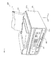
- FIG. 1 is a perspective view illustrating an appearance of the printer according to one or more embodiments of the present invention.
- a printer 100 comprises a casing 101.
- a paper feed tray 102 for setting a recording medium 10 before printing is provided in a rear panel 101a of the casing 101.
- the recording medium 10 is paper (for example, normal paper, photographic paper, or the like), a label surface for disc media (for example, a CD, a DVD, a Blu-ray [registered trademark] disc, or the like), or the like.
- a paper discharge tray 103 into which a printed recording medium 10 is discharged is provided in a front panel 101b of the casing 101.
- an operation unit 104 for accepting various operations from a user is provided in the front panel 101b of the casing 101.
- FIG. 2 is a perspective view illustrating the internal structure of the printer according to one or more embodiments of the present invention.
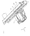
- FIG. 3 is a partial side view illustrating a carriage vicinity of the printer according to one or more embodiments of the present invention.
- illustration of several components is omitted. This is to prevent the drawings from becoming needlessly complex.
- the printer 100 comprises a carriage 110, a guide shaft 120, a frame 130, and a motor 140 inside the casing 101.
- a plurality of heads 111 is mounted to the carriage 110.
- Each of the plurality of heads 111 has a nozzle 111a for discharging ink.
- ink cartridges of black, cyan, magenta, and yellow are loaded to the plurality of heads 111.
- the carriage 110 When printing an image on the recording medium 10, the carriage 110 is driven by the motor 140 and reciprocates along the guide shaft 120 extending in an X-axis direction. Moreover, the recording medium 10 is conveyed in a direction (Y-axis direction) indicated by arrow P in FIG. 2 by a conveyance roller 150 disposed inside the casing 101. At this time, the image is printed on the recording medium 10 by the ink being discharged toward the recording medium 10 from the nozzles 111a of each head 111.
- a lever 112 is installed to the carriage 110. Moreover, the lever 112 is connected to a cam 113. The lever 112 and the cam 113 move in the X-axis direction along with the carriage 110. Details concerning the lever 112 and the cam 113 will be described using the drawings.
- the guide shaft 120 extends in a direction (X-axis direction) substantially orthogonal to a conveyance direction (Y-axis direction) of the recording medium 10 and guides movement of the carriage 110 in the X-axis direction.
- the guide shaft 120 is a rod member made of metal that penetrates the carriage 110 and has a cross section of a circular shape.
- the frame 130 supports the guide shaft 120. Specifically, the guide shaft 120 is inserted into a hole formed in a side surface of the frame 130. Moreover, a rotational shaft portion of the cam 113 for adjusting the gap is inserted in a groove formed in an upper surface of the frame 130 so as to be movable in the X-axis direction and rotatable.
- the motor 140 is an example of a drive source.
- the motor 140 reciprocates the carriage 110 in the X-axis direction via a power transmission mechanism (not illustrated) such as a gear or a belt by rotating in a positive direction and a reverse direction.
- FIG. 4 is a partial perspective view illustrating the carriage vicinity of the printer according to one or more embodiments of the present invention.
- FIG. 5 is a partial perspective view illustrating the lever and the cam of the printer according to one or more embodiments of the present invention. Note that in FIG. 5 , a state is illustrated where a portion of the carriage is removed to expose the lever.
- FIG. 6 is a perspective view of the lever according to one or more embodiments of the present invention.
- FIG. 7 is a perspective view of the cam relating to the embodiment.
- the lever 112 is installed to the carriage 110. This lever 112 is installed so one end (lower end 112a) of the lever 112 contacts a surface of the recording medium 10 when the recording medium 10 passes below. Another end (upper end 112b) of the lever 112 is connected to the cam 113.
- the lever 112 is installed so an inclination of the lever 112 changes according to the thickness of the recording medium 10 (i.e., thickness between a surface of the paper feed tray 102 and a top surface of the recording medium 10).
- the lever 112 is supported in a rotatable manner by the carriage 110 via a rotational shaft 112c formed on the lever 112. Therefore, if the thickness of the recording medium 10 changes, the lever 112 rotates around the rotational shaft 112c, and an inclination relative to the recording medium 10 changes.
- the thickness of the recording medium may change, e.g., if the recording medium is paper, the thickness changes based on the number of sheets of paper.
- a spring 114 biases the lever 112 in a counterclockwise manner seen from a positive direction (right side) of the X axis. That is, the spring 114 biases the lower end 112a of the lever 112 in a direction approaching the surface of the recording medium 10. By this, the lower end 112a of the lever 112 can be prevented from separating from the surface of the recording medium 10 if the thickness of the recording medium 10 is reduced.
- the lever 112 is formed with a protruding portion 112d that protrudes in a direction orthogonal to a longitudinal direction of the lever.
- a sensor 115 illustrated in FIG. 5 detects a presence or absence of the recording medium 10 by sensing whether this protruding portion 112d is present in a predetermined position.
- the sensor 115 is, for example, a photo interrupter having a light-emitting portion and a light-receiving portion. The sensor 115 is disposed so a light emitted from the light-emitting portion to the light-receiving portion is blocked by the protruding portion 112d when the recording medium 10 is not present.
- the cam 113 is formed with a rotational shaft portion 113b with a circular cross section that protrudes from a main body portion 113a.
- This rotational shaft portion 113b is inserted in the groove 130a extending in the X-axis direction formed in the frame 130 so as to be movable in the X-axis direction and rotatable.
- the cam 113 is connected to the upper end 112b of the lever 112, and the rotational angle thereof changes according to the inclination of the lever 112.
- a groove portion 113c is formed in a circumferential direction of the main body portion 113a of the cam 113 so a distance relative to a rotational center of the rotational shaft portion 113b changes.
- the upper end 112b of the lever 112 is inserted in this groove portion 113c.
- the upper end 112b of the lever 112 attempts to move relatively along the groove portion 113c to a position corresponding to a distance between the upper end 112b of the lever 112 and the rotational center of the cam 113.
- the cam 113 rotates to a rotational angle corresponding to the distance between the upper end 112b ofthe lever 112 and the rotational center of the cam 113.
- FIG. 8 is a cross-sectional view illustrating the internal structure of the cam according to one or more embodiments of the present invention.
- the cam 113 is formed with a concave portion 113d of a circular shape in a position shifted from the rotational center of the rotational shaft portion 113b.
- a connecting member 116 is inserted into this concave portion 113. That is, the connecting member 116 is connected in a rotatable manner in the position shifted from the rotational center of the cam 113.
- the connecting member 116 revolves around the rotational center of the cam 113 while spinning. That is, if the cam 113 rotates, a position in the Y-axis direction of the connecting member 116 changes, and thus the orientation of the carriage 110 changes. That is, the connecting member 116 changes the orientation of the carriage 110 according to the rotational angle of the cam 113.
- the carriage 110 is biased in a clockwise manner relative to the guide shaft 120 seen from the positive direction (right side) of the X-axis by a spring or the like that is not illustrated. Therefore, if the connecting member 116 moves in a negative direction of the Y axis, the carriage 110 also rotates in the clockwise manner in conjunction thereto. Conversely, if the connecting member 116 moves in the positive direction of the Y axis, an upper portion of the carriage 110 is pushed out by the connecting member 116 and the carriage 110 rotates in the counterclockwise manner.
- a state where the recording medium is not present below the carriage will be referred to as a first state
- a state where a recording medium 10a of a first thickness is present will be referred to as a second state
- a state where a recording medium 10b of a second thickness that is greater than the first thickness will be referred to as a third state.
- FIGS. 9A to 9C are partial side views illustrating the carriage vicinity in the first to third states.
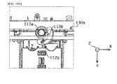
- FIGS. 10A to 10C are partial plan views illustrating the carriage vicinity in the first to third states.
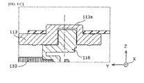
- FIGS. 11A to 11C are partial cross-sectional views illustrating a cam vicinity in the first to third states.
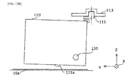
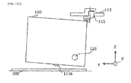
- FIGS. 12A to 12C are conceptual diagrams illustrating orientations of the carriage in the first to third states.
- the lever 112 in the first state, the lever 112 is upright, and the upper end 112b of the lever 112 is away from the rotational center of the cam 113. Moreover, the connecting member 116 is connected more on a carriage side than the rotational center of the cam 113 and pushes out the carriage 110. As a result, the carriage 110 assumes an upright orientation as illustrated in FIG. 12A .
- the upper end 112b of the lever 112 approaches the rotational center ofthe cam 113 and rotates the cam 113. That is, the cam 113 rotates to a first rotational angle corresponding to the inclination ofthe lever 112.
- the connecting member 116 moves in a direction (negative direction of the Y axis) away from the carriage 110.
- the orientation of the carriage 110 changes as illustrated in FIG. 12B in conjunction with this movement of the connecting member 116. That is, the carriage 110 rotates around the guide shaft 120, and the nozzle 111a moves upward.
- the lower end 112a of the lever 112 is pushed up further by the recording medium 10b.
- the lever 112 rotates around the rotational shaft 112c and inclines further than the second state. That is, the inclination of the lever 112 changes to an inclination corresponding to the second thickness of the recording medium 10b.
- the lever 112 inclining further, the upper end 112b of the lever 112 further approaches the rotational center of the cam 113 and further rotates the cam 113. That is, the cam 113 rotates to a second rotational angle corresponding to the inclination of the lever 112.
- the connecting member 116 moves further in the direction (negative direction of the Y axis) away from the carriage 110.
- the orientation of the carriage 110 changes as illustrated in FIG. 12C in conjunction with this movement of the connecting member 116. That is, the carriage 110 rotates around the guide shaft 120, and the nozzle 111a moves further upward. That is, fluctuation of the gap between the nozzle and the recording medium is suppressed.
- the inclination of the lever changes according to the thickness of the recording medium
- the rotational angle of the cam changes according to the inclination of the lever
- the orientation of the carriage changes according to the rotational angle of the cam. That is, the orientation of the carriage can be changed according to the thickness of the recording medium, and the gap between the nozzle and the recording medium can be appropriately maintained even if the thickness of the recording medium changes. That is, the gap between the nozzle and the recoding medium can be adjusted by a simple configuration without using a drive source for adjusting the gap.
- the other end of the lever is inserted in the groove portion formed in the circumferential direction of the cam so the distance relative to the rotational center of the cam changes.
- the other end of the lever attempts to move relatively along the groove portion to the position corresponding to the distance between the other end of the lever and the rotational center of the cam.
- the cam rotates.
- the groove portion formed in the cam the rotational angle of the cam can be changed according to the inclination of the lever by a simpler configuration, and the gap between the nozzle and the recording medium can be adjusted.
- the connecting member is connected to the position shifted from the rotational center of the cam. Therefore, if the cam rotates, the connecting member moves around the rotational center of the cam, and the orientation of the carriage can be changed.
- the rotational shaft portion of the cam is inserted in the groove extending in the predetermined direction formed in the upper surface of the frame so as to be movable in the predetermined direction and rotatable. Therefore, the cam can change the rotational angle according to the thickness of the recording medium while moving in the predetermined direction along with the carriage.
- the lever for adjusting the gap can be used to further detect the presence or absence of the recording medium.
- Embodiments of a printer according to one aspect of the present invention are described above, but the present invention is not limited to these embodiments. Various modifications conceived by persons skilled in the art applied to the embodiments are also included within the scope of the present invention.
- the printer is provided with the connecting member connected to the cam but is not limited thereto.
- a convex portion that is a convex portion with a circular cross section that protrudes to a lower surface (surface on an opposite side of the rotational shaft portion) of the main body portion of the cam and is eccentric relative to the rotational center may be integrally formed with the main body portion. This convex portion changes the orientation of the carriage.
- connection method of the connecting member and the carriage is not limited to the above embodiments.
- the connecting member and the carriage may be locked.
- the connecting member may be integrally molded with the carriage.
- the protruding portion for detecting the presence or absence of the recording medium is provided on the lever, but the protruding portion does not necessarily need to be provided. That is, the presence or absence of the recording medium does not necessarily need to be detected using the lever. Even in this situation, the gap between the recording medium and the nozzle can be adjusted.
- the rotational shaft portion of the cam is inserted in the groove formed in the frame but is not limited thereto.
- the rotational shaft portion of the cam may be inserted in a groove formed in a member other than the frame.
- the present invention can be applied as, for example, an inkjet printer that performs printing by discharging ink onto a recording medium.
Landscapes
- Common Mechanisms (AREA)
- Ink Jet (AREA)
Abstract
Description
- The present invention relates generally to a printer that can adjust a gap between a nozzle that discharges ink and a recording medium of a sheet shape.
- There are various thicknesses to recording mediums (for example, paper, label surfaces of disc media, and the like) of a sheet shape used with inkjet printers. If a thickness of a recording medium changes, a distance from a nozzle that discharges ink to the recording medium (also referred to as a "paper gap" below) also fluctuates. Moreover, the paper gap also fluctuates due to variations in component sizes and the like. Moreover, the fluctuations in the paper gap lead to reductions in print quality.
- In contrast, in Patent Literature 1, adjustor motor moves a carriage vertically according to a gap detected using a detection lever. By this, an appropriate gap is set.
- [Patent Literature 1] Japanese Unexamined Patent Application Publication No.
2001-71581 - However, in the conventional technology, a motor for adjusting the gap is necessary, complicating the structure of the printer.
- One or more embodiments of the present invention provide a printer that can adjust a gap between a nozzle and a recording medium by a simple configuration.
- For example, a printer according to one or more embodiments of the present invention may be a printer that can adjust a gap between a recording medium of a sheet shape and a nozzle that discharges ink onto the recording medium, provided with: a carriage mounted with a head having the nozzle; a lever that is installed so one end thereof contacts a surface of the recording medium and whose inclination changes according to a thickness of the recording medium; and a cam that is connected to another end of the lever, is a cam whose rotational angle changes according to the inclination of the lever, and adjusts the gap by changing an attitude of the carriage according to the change in the rotational angle.
- According to one or more embodiments of this configuration, the inclination of the lever changes according to the thickness of the recording medium, the rotational angle of the cam changes according to the inclination of the lever, and the attitude of the carriage changes according to the rotational angle of the cam. That is, the attitude of the carriage can be changed according to the thickness of the recording medium, and the gap between the nozzle and the recording medium can be appropriately maintained even if the thickness of the recording medium changes. That is, the gap between the nozzle and the recoding medium can be adjusted by a simple configuration without using a drive source for adjusting the gap.
- For example, according to one or more embodiments, the cam may have a groove portion formed in a circumferential direction so a distance relative to a rotational center of the cam changes, and another end of the lever may be inserted in the groove portion of the cam.
- According to one or more embodiments of this configuration, the other end of the lever is inserted in the groove portion formed in the circumferential direction of the cam so the distance relative to the rotational center of the cam changes. This means that when the inclination of the lever changes, the other end of the lever attempts to move relatively along the groove portion to a position corresponding to a distance between the other end of the lever and the rotational center of the cam. However, because the other end of the lever cannot move freely along the groove portion, the cam rotates. In this manner, by the groove portion formed in the cam, the rotational angle of the cam can be changed according to the inclination of the lever by a simpler configuration, and the gap between the nozzle and the recording medium can be adjusted.
- For example, according to one or more embodiments, the printer may be further provided with a connecting member that is connected to a position shifted from the rotational center of the cam and changes the attitude of the carriage according to the rotational angle of the cam.
- According to one or more embodiments of this configuration, the connecting member is connected to the position shifted from the rotational center of the cam. Therefore, if the cam rotates, the connecting member moves around the rotational center of the cam, and the attitude of the carriage can be changed.
- For example, according to one or more embodiments, the printer may be further provided with a guide shaft that guides movement of the carriage in a predetermined direction, and a frame that supports the guide shaft; wherein a rotational shaft portion of the cam is inserted in a groove extending in the predetermined direction formed in an upper surface of the frame so as to be movable in the predetermined direction and rotatable.
- According to one or more embodiments of this configuration, the rotational shaft portion of the cam is inserted in the groove extending in the predetermined direction formed in the upper surface of the frame so as to be movable in the predetermined direction and rotatable. Therefore, the cam can change the rotational angle according to the thickness of the recording medium while moving in the predetermined direction along with the carriage.
- For example, according to one or more embodiments, the lever may be provided with a protruding portion that protrudes in a direction orthogonal to a longitudinal direction, and the printer may be further provided with a sensor that detects a presence or absence of the recording medium by sensing whether the protruding portion is present in a predetermined position.
- According to one or more embodiments of this configuration, the lever for adjusting the gap can be used to further detect the presence or absence of the recording medium.
- The printer according to one or more embodiments of the present invention can adjust the gap between the nozzle and the recording medium by the simple configuration.
-
- [
FIG. 1 ] This is a perspective view illustrating an appearance of a printer according to an embodiment. - [
FIG. 2 ] This is a perspective view illustrating an internal structure of the printer according to the embodiment. - [
FIG. 3 ] This is a partial side view illustrating a carriage vicinity of the printer according to the embodiment. - [
FIG. 4 ] This is a partial perspective view illustrating the carriage vicinity of the printer according to the embodiment. - [
FIG. 5 ] This is a partial perspective view illustrating a lever and a cam of the printer according to the embodiment. - [
FIG. 6 ] This is a perspective view of the lever according to the embodiment. - [
FIG. 7 ] This is a perspective view of the cam according to the embodiment. - [
FIG. 8 ] This is a cross-sectional view illustrating an internal structure of the cam according to the embodiment. - [
FIG. 9A ] This is a partial side view illustrating the carriage vicinity in a first state. - [
FIG. 9B ] This is a partial side view illustrating the carriage vicinity in a second state. - [
FIG. 9C ] This is a partial side view illustrating the carriage vicinity in a third state. - [
FIG. 10A ] This is a partial plan view illustrating the carriage vicinity in the first state. - [
FIG. 10B ] This is a partial plan view illustrating the carriage vicinity in the second state. - [
FIG. 10C ] This is a partial plan view illustrating the carriage vicinity in the third state. - [
FIG. 11A ] This is a partial cross-sectional view illustrating a cam vicinity in the first state. - [
FIG. 11B ] This is a partial cross-sectional view illustrating the cam vicinity in the second state. - [
FIG. 11C ] This is a partial cross-sectional view illustrating the cam vicinity in the third state. - [
FIG. 12A ] This is a conceptual diagram illustrating an orientation of the carriage in the first state. - [
FIG. 12B ] This is a conceptual diagram illustrating an orientation of the carriage in the second state. - [
FIG. 12C ] This is a conceptual diagram illustrating an orientation of the carriage in the third state. - Embodiments will be specifically described below with reference to drawings.
- Each embodiment that will be described below illustrates a comprehensive or specific example. Numeric values, shapes, materials, components, disposition positions of the components, connection modes, and the like illustrated in the embodiments below are but examples and are not intended to limit the scope of the claims. Moreover, among the components in the embodiments below, those not described in the appended independent claim(s) have to be considered as optional components.
- A printer according to one or more embodiments of the present invention is provided with a lever that is installed to a carriage so an inclination of the lever changes according to a thickness of a recording medium of a sheet shape, and a cam whose rotational angle changes according to the inclination of the lever. Moreover, an orientation of the carriage changes according to the change in the rotational angle of the cam. By this, a gap between a nozzle and the recording medium is adjusted according to the thickness of the recording medium. Such a printer according to one or more embodiments of the present invention will be specifically described below while referencing the drawings.
- First, an external structure of the printer according to one or more embodiments will be described while referencing
FIG. 1. FIG. 1 is a perspective view illustrating an appearance of the printer according to one or more embodiments of the present invention. - A
printer 100 comprises acasing 101. Apaper feed tray 102 for setting arecording medium 10 before printing is provided in arear panel 101a of thecasing 101. Therecording medium 10 is paper (for example, normal paper, photographic paper, or the like), a label surface for disc media (for example, a CD, a DVD, a Blu-ray [registered trademark] disc, or the like), or the like. - A
paper discharge tray 103 into which a printedrecording medium 10 is discharged is provided in afront panel 101b of thecasing 101. Moreover, anoperation unit 104 for accepting various operations from a user is provided in thefront panel 101b of thecasing 101. - Next, an internal structure of the printer will be described while referencing
FIGS. 2 and3 .FIG. 2 is a perspective view illustrating the internal structure of the printer according to one or more embodiments of the present invention. Moreover,FIG. 3 is a partial side view illustrating a carriage vicinity of the printer according to one or more embodiments of the present invention. InFIGS. 2 and3 , illustration of several components is omitted. This is to prevent the drawings from becoming needlessly complex. - As illustrated in
FIG. 2 , theprinter 100 comprises acarriage 110, aguide shaft 120, aframe 130, and amotor 140 inside thecasing 101. - A plurality of
heads 111 is mounted to thecarriage 110. Each of the plurality ofheads 111 has anozzle 111a for discharging ink. Moreover, ink cartridges of black, cyan, magenta, and yellow are loaded to the plurality ofheads 111. - When printing an image on the
recording medium 10, thecarriage 110 is driven by themotor 140 and reciprocates along theguide shaft 120 extending in an X-axis direction. Moreover, therecording medium 10 is conveyed in a direction (Y-axis direction) indicated by arrow P inFIG. 2 by aconveyance roller 150 disposed inside thecasing 101. At this time, the image is printed on therecording medium 10 by the ink being discharged toward therecording medium 10 from thenozzles 111a of eachhead 111. - A
lever 112 is installed to thecarriage 110. Moreover, thelever 112 is connected to acam 113. Thelever 112 and thecam 113 move in the X-axis direction along with thecarriage 110. Details concerning thelever 112 and thecam 113 will be described using the drawings. - The
guide shaft 120 extends in a direction (X-axis direction) substantially orthogonal to a conveyance direction (Y-axis direction) of therecording medium 10 and guides movement of thecarriage 110 in the X-axis direction. For example, theguide shaft 120 is a rod member made of metal that penetrates thecarriage 110 and has a cross section of a circular shape. - The
frame 130 supports theguide shaft 120. Specifically, theguide shaft 120 is inserted into a hole formed in a side surface of theframe 130. Moreover, a rotational shaft portion of thecam 113 for adjusting the gap is inserted in a groove formed in an upper surface of theframe 130 so as to be movable in the X-axis direction and rotatable. - The
motor 140 is an example of a drive source. Themotor 140 reciprocates thecarriage 110 in the X-axis direction via a power transmission mechanism (not illustrated) such as a gear or a belt by rotating in a positive direction and a reverse direction. - Next, the lever and the cam will be described while referencing
FIGS. 4 to 8 .FIG. 4 is a partial perspective view illustrating the carriage vicinity of the printer according to one or more embodiments of the present invention.FIG. 5 is a partial perspective view illustrating the lever and the cam of the printer according to one or more embodiments of the present invention. Note that inFIG. 5 , a state is illustrated where a portion of the carriage is removed to expose the lever.FIG. 6 is a perspective view of the lever according to one or more embodiments of the present invention.FIG. 7 is a perspective view of the cam relating to the embodiment. - As illustrated in
FIG. 5 , thelever 112 is installed to thecarriage 110. Thislever 112 is installed so one end (lower end 112a) of thelever 112 contacts a surface of therecording medium 10 when therecording medium 10 passes below. Another end (upper end 112b) of thelever 112 is connected to thecam 113. - Furthermore, the
lever 112 is installed so an inclination of thelever 112 changes according to the thickness of the recording medium 10 (i.e., thickness between a surface of thepaper feed tray 102 and a top surface of the recording medium 10). Specifically, thelever 112 is supported in a rotatable manner by thecarriage 110 via arotational shaft 112c formed on thelever 112. Therefore, if the thickness of therecording medium 10 changes, thelever 112 rotates around therotational shaft 112c, and an inclination relative to therecording medium 10 changes. The thickness of the recording medium may change, e.g., if the recording medium is paper, the thickness changes based on the number of sheets of paper. - A
spring 114 biases thelever 112 in a counterclockwise manner seen from a positive direction (right side) of the X axis. That is, thespring 114 biases thelower end 112a of thelever 112 in a direction approaching the surface of therecording medium 10. By this, thelower end 112a of thelever 112 can be prevented from separating from the surface of therecording medium 10 if the thickness of therecording medium 10 is reduced. - As illustrated in
FIG. 6 , thelever 112 is formed with a protrudingportion 112d that protrudes in a direction orthogonal to a longitudinal direction of the lever. Asensor 115 illustrated inFIG. 5 detects a presence or absence of therecording medium 10 by sensing whether this protrudingportion 112d is present in a predetermined position. Specifically, thesensor 115 is, for example, a photo interrupter having a light-emitting portion and a light-receiving portion. Thesensor 115 is disposed so a light emitted from the light-emitting portion to the light-receiving portion is blocked by the protrudingportion 112d when therecording medium 10 is not present. - As illustrated in
FIG. 4 ,5 , and7 , thecam 113 is formed with arotational shaft portion 113b with a circular cross section that protrudes from amain body portion 113a. Thisrotational shaft portion 113b is inserted in thegroove 130a extending in the X-axis direction formed in theframe 130 so as to be movable in the X-axis direction and rotatable. - Furthermore, the
cam 113 is connected to theupper end 112b of thelever 112, and the rotational angle thereof changes according to the inclination of thelever 112. Specifically, agroove portion 113c is formed in a circumferential direction of themain body portion 113a of thecam 113 so a distance relative to a rotational center of therotational shaft portion 113b changes. Moreover, theupper end 112b of thelever 112 is inserted in thisgroove portion 113c. - Therefore, when the inclination of the
lever 112 changes, theupper end 112b of thelever 112 attempts to move relatively along thegroove portion 113c to a position corresponding to a distance between theupper end 112b of thelever 112 and the rotational center of thecam 113. However, because theupper end 112b of thelever 112 cannot move freely along thegroove portion 113c, thecam 113 rotates to a rotational angle corresponding to the distance between theupper end 112b ofthelever 112 and the rotational center of thecam 113. - Here, an internal structure of the
cam 113 for changing the orientation of thecarriage 110 will be described.FIG. 8 is a cross-sectional view illustrating the internal structure of the cam according to one or more embodiments of the present invention. - As illustrated in
FIG. 8 , thecam 113 is formed with aconcave portion 113d of a circular shape in a position shifted from the rotational center of therotational shaft portion 113b. A connectingmember 116 is inserted into thisconcave portion 113. That is, the connectingmember 116 is connected in a rotatable manner in the position shifted from the rotational center of thecam 113. - Therefore, if the
cam 113 rotates, the connectingmember 116 revolves around the rotational center of thecam 113 while spinning. That is, if thecam 113 rotates, a position in the Y-axis direction of the connectingmember 116 changes, and thus the orientation of thecarriage 110 changes. That is, the connectingmember 116 changes the orientation of thecarriage 110 according to the rotational angle of thecam 113. - In the present embodiment, the
carriage 110 is biased in a clockwise manner relative to theguide shaft 120 seen from the positive direction (right side) of the X-axis by a spring or the like that is not illustrated. Therefore, if the connectingmember 116 moves in a negative direction of the Y axis, thecarriage 110 also rotates in the clockwise manner in conjunction thereto. Conversely, if the connectingmember 116 moves in the positive direction of the Y axis, an upper portion of thecarriage 110 is pushed out by the connectingmember 116 and thecarriage 110 rotates in the counterclockwise manner. - Next, an operation of the printer for gap adjustment will be described while referencing
FIGS. 9A to 12C . Note that below, a state where the recording medium is not present below the carriage will be referred to as a first state, a state where arecording medium 10a of a first thickness is present will be referred to as a second state, and a state where arecording medium 10b of a second thickness that is greater than the first thickness will be referred to as a third state. -
FIGS. 9A to 9C are partial side views illustrating the carriage vicinity in the first to third states.FIGS. 10A to 10C are partial plan views illustrating the carriage vicinity in the first to third states.FIGS. 11A to 11C are partial cross-sectional views illustrating a cam vicinity in the first to third states.FIGS. 12A to 12C are conceptual diagrams illustrating orientations of the carriage in the first to third states. - As illustrated in
FIGS. 9A ,10A , and11A , in the first state, thelever 112 is upright, and theupper end 112b of thelever 112 is away from the rotational center of thecam 113. Moreover, the connectingmember 116 is connected more on a carriage side than the rotational center of thecam 113 and pushes out thecarriage 110. As a result, thecarriage 110 assumes an upright orientation as illustrated inFIG. 12A . - As illustrated in
FIGS. 9B ,10B , and11B , in the second state, thelower end 112a of thelever 112 is pushed up by therecording medium 10a. By this, thelever 112 rotates around therotational shaft 112c and the inclination thereof changes. That is, the inclination of thelever 112 changes to an inclination corresponding to the first thickness oftherecording medium 10a. - Furthermore, by the inclination of the
lever 112 changing, theupper end 112b of thelever 112 approaches the rotational center ofthecam 113 and rotates thecam 113. That is, thecam 113 rotates to a first rotational angle corresponding to the inclination ofthelever 112. - By the
cam 113 rotating in this manner, the connectingmember 116 moves in a direction (negative direction of the Y axis) away from thecarriage 110. The orientation of thecarriage 110 changes as illustrated inFIG. 12B in conjunction with this movement of the connectingmember 116. That is, thecarriage 110 rotates around theguide shaft 120, and thenozzle 111a moves upward. - As illustrated in
FIGS. 9C ,10C , and11C , in the third state, thelower end 112a of thelever 112 is pushed up further by therecording medium 10b. By this, thelever 112 rotates around therotational shaft 112c and inclines further than the second state. That is, the inclination of thelever 112 changes to an inclination corresponding to the second thickness of therecording medium 10b. - Furthermore, by the
lever 112 inclining further, theupper end 112b of thelever 112 further approaches the rotational center of thecam 113 and further rotates thecam 113. That is, thecam 113 rotates to a second rotational angle corresponding to the inclination of thelever 112. - By the
cam 113 rotating in this manner, the connectingmember 116 moves further in the direction (negative direction of the Y axis) away from thecarriage 110. The orientation of thecarriage 110 changes as illustrated inFIG. 12C in conjunction with this movement of the connectingmember 116. That is, thecarriage 110 rotates around theguide shaft 120, and thenozzle 111a moves further upward. That is, fluctuation of the gap between the nozzle and the recording medium is suppressed. - According to one or more embodiments of the present invention, the inclination of the lever changes according to the thickness of the recording medium, the rotational angle of the cam changes according to the inclination of the lever, and the orientation of the carriage changes according to the rotational angle of the cam. That is, the orientation of the carriage can be changed according to the thickness of the recording medium, and the gap between the nozzle and the recording medium can be appropriately maintained even if the thickness of the recording medium changes. That is, the gap between the nozzle and the recoding medium can be adjusted by a simple configuration without using a drive source for adjusting the gap.
- Furthermore, according to one or more embodiments of the present invention, the other end of the lever is inserted in the groove portion formed in the circumferential direction of the cam so the distance relative to the rotational center of the cam changes. This means that when the inclination of the lever changes, the other end of the lever attempts to move relatively along the groove portion to the position corresponding to the distance between the other end of the lever and the rotational center of the cam. At this time, because the other end of the lever cannot move freely along the groove portion, the cam rotates. In this manner, by the groove portion formed in the cam, the rotational angle of the cam can be changed according to the inclination of the lever by a simpler configuration, and the gap between the nozzle and the recording medium can be adjusted.
- Furthermore, according to one or more embodiments of the present invention, the connecting member is connected to the position shifted from the rotational center of the cam. Therefore, if the cam rotates, the connecting member moves around the rotational center of the cam, and the orientation of the carriage can be changed.
- Furthermore, according to one or more embodiments of the present invention, the rotational shaft portion of the cam is inserted in the groove extending in the predetermined direction formed in the upper surface of the frame so as to be movable in the predetermined direction and rotatable. Therefore, the cam can change the rotational angle according to the thickness of the recording medium while moving in the predetermined direction along with the carriage.
- Furthermore, according to one or more embodiments of the present invention, the lever for adjusting the gap can be used to further detect the presence or absence of the recording medium.
- Embodiments of a printer according to one aspect of the present invention are described above, but the present invention is not limited to these embodiments. Various modifications conceived by persons skilled in the art applied to the embodiments are also included within the scope of the present invention.
- For example, in the above embodiments, the printer is provided with the connecting member connected to the cam but is not limited thereto. For example, a convex portion that is a convex portion with a circular cross section that protrudes to a lower surface (surface on an opposite side of the rotational shaft portion) of the main body portion of the cam and is eccentric relative to the rotational center may be integrally formed with the main body portion. This convex portion changes the orientation of the carriage.
- A connection method of the connecting member and the carriage is not limited to the above embodiments. According to one or more embodiments, the connecting member and the carriage may be locked. Moreover, the connecting member may be integrally molded with the carriage.
- In the above embodiments, the protruding portion for detecting the presence or absence of the recording medium is provided on the lever, but the protruding portion does not necessarily need to be provided. That is, the presence or absence of the recording medium does not necessarily need to be detected using the lever. Even in this situation, the gap between the recording medium and the nozzle can be adjusted.
- In the above embodiments, the rotational shaft portion of the cam is inserted in the groove formed in the frame but is not limited thereto. For example, the rotational shaft portion of the cam may be inserted in a groove formed in a member other than the frame.
- The present invention can be applied as, for example, an inkjet printer that performs printing by discharging ink onto a recording medium.
- Although the disclosure has been described with respect to only a limited number of embodiments, those skilled in the art, having benefit of this disclosure, will appreciate that various other embodiments may be devised without departing from the scope of the present invention. In particular, the features of these embodiments can be combined with each other according to various combinations, not limited to the specific combinations disclosed herein. Accordingly, the scope of the present invention should be limited only by the attached claims.
-
- 10, 10a, 10b Recording medium
- 100 Printer
- 101 Casing
- 101a Rear panel
- 101b Front panel
- 102 Paper feed tray
- 103 Paper discharge tray
- 104 Operation unit
- 110 Carriage
- 111 Head
- 111a Nozzle
- 112 Lever
- 112a Lower end
- 112b Upper end
- 112c Rotational shaft
- 112d Protruding portion
- 113 Cam
- 113a Main body portion
- 113b Rotational shaft portion
- 113c Groove portion
- 113d Concave portion
- 114 Spring
- 115 Sensor
- 116 Connecting member
- 120 Guide shaft
- 130 Frame
- 130a Groove
- 140 Motor
- 150 Conveyance roller
Claims (15)
- A printer, comprising:a carriage (110) mounted with a head (111) comprising a nozzle (111a) that discharges ink onto a recording medium (10, 10a, 10b);a lever (112) comprising a first end (112a) that contacts a surface of the recording medium (10, 10a, 10b), wherein the lever (112) is disposed such that an inclination of the lever (112) relative to a vertical direction of the surface changes based on a thickness of the recording medium (10, 10a, 10b); anda cam (113) that changes an orientation of the carriage (110) based on the inclination of the lever (112).
- The printer according to claim 1, whereinthe cam (113) comprises a groove portion (113c) formed in a circumferential direction of the cam; andthe lever (112) further comprises a second end (112b) inserted in the groove portion (113c) of the cam so that a distance between the second end and the rotational center of the cam changes based on the inclination of the lever (112).
- The printer according to claim 2, further comprising:a connecting member (116) connected to the cam (113) at a position other than the rotational center of the cam, wherein the connecting member (116) changes the orientation of the carriage (110) based on a rotational angle of the cam (113).
- The printer according to claim 3, whereinthe cam (113) comprises a circular concave portion (113d) at a position other than the rotational center of the cam (113).
- The printer according to any of claims 1 to 4, whereinthe lever (112) is rotatably supported by the carriage (110), andthe inclination of the lever (112) relative to the vertical direction of the surface increases as the thickness of the recording medium (10, 10a, 10b) increases.
- The printer according to claim 5, wherein the lever (112) further comprises a spring portion biased in a direction that presses the surface.
- The printer according to any of claims 1 to 6, further comprising:a discharge port that discharges the recording medium (10, 10a, 10b), whereinthe carriage (110) is biased with a guide shaft (120) as a fulcrum on a discharge port side so as to rotate in a direction in which a distance between the surface of the recording medium (10, 10a, 10b) and a carriage bottom surface increases.
- The printer according to any of claims 1 to 7, further comprising:a guide shaft (120) that guides movement of the carriage (110) in a predetermined direction;a frame (130) that supports the guide shaft (120), whereina rotational shaft portion (113b) of the cam (113) is inserted in a groove formed in an upper surface of the frame (130) in a predetermined direction so that the rotatable shaft portion (113b) is movable and rotatable in the predetermined direction.
- The printer according to any of claims 1 to 8, wherein:the lever (112) comprises a protrusion portion (112d) that protrudes in a direction orthogonal to a longitudinal direction of the lever; andthe printer further comprises a sensor (115) that detects a presence of the recording medium (10, 10a, 10b) by sensing the protrusion portion (112d) in a predetermined location.
- A printer, comprising:a carriage (110) mounted with a head (111);a thickness detecting unit (112) that changes an inclination thereof based on a thickness between a surface of a paper feed tray (102) of the printer and a top surface of a recording medium (10, 10a, 10b) on the paper feed tray (102); anda rotating unit (113) that changes an orientation of the carriage (110) based on the inclination of the thickness detecting unit (112).
- The printer according to claim 10, wherein the thickness detecting unit (112) is rotatably supported by the carriage (110) and is configured such that the inclination relative to a vertical direction of the top surface of the recording medium (10, 10a, 10b) changes as the thickness increases.
- The printer according to claim 11, whereinthe rotating unit (113) comprises a groove portion (113c) formed in a circumferential direction of the rotating unit; andthe thickness detecting unit (112) comprises a first end (112a) and a second end (112b), wherein the second end (112b) is inserted in the groove portion (113c) of the rotating unit (113) so that a distance between the second end (112b) and the rotational center of the rotating unit (113) changes based on the inclination of the thickness detecting unit (112).
- The printer according to claim 12, further comprising:a connecting member (116) connected to the rotating unit (113) at a position other than the rotational center of the rotating unit (113), wherein the connecting member (116) changes the orientation of the carriage (110) based on a rotational angle of the rotating unit (113).
- The printer according to claim 13, wherein the connecting member (116) comprises a circular concave portion (113d) at a position other than the rotational center of the rotating unit (113), and the thickness detecting unit (112) comprises a spring portion biased in a direction that presses the surface.
- The printer according to claim 11, further comprising:a discharge port that discharges the recording medium (10, 10a, 10b), whereinthe carriage (110) is biased with the guide shaft (120) as a fulcrum on a discharge port side so as to rotate in a direction in which a distance between the surface of the recording medium (10, 10a, 10b) and a carriage bottom surface increases.
Applications Claiming Priority (1)
| Application Number | Priority Date | Filing Date | Title |
|---|---|---|---|
| JP2014017342A JP2015142994A (en) | 2014-01-31 | 2014-01-31 | printer |
Publications (1)
| Publication Number | Publication Date |
|---|---|
| EP2902208A1 true EP2902208A1 (en) | 2015-08-05 |
Family
ID=52440594
Family Applications (1)
| Application Number | Title | Priority Date | Filing Date |
|---|---|---|---|
| EP15153370.0A Withdrawn EP2902208A1 (en) | 2014-01-31 | 2015-01-30 | Printer |
Country Status (3)
| Country | Link |
|---|---|
| US (1) | US9216584B2 (en) |
| EP (1) | EP2902208A1 (en) |
| JP (1) | JP2015142994A (en) |
Cited By (1)
| Publication number | Priority date | Publication date | Assignee | Title |
|---|---|---|---|---|
| CN107379766A (en) * | 2016-04-21 | 2017-11-24 | 精工电子打印科技有限公司 | Balladeur train and fluid jet recording apparatus |
Families Citing this family (3)
| Publication number | Priority date | Publication date | Assignee | Title |
|---|---|---|---|---|
| JP6581489B2 (en) * | 2015-12-11 | 2019-09-25 | エスアイアイ・プリンテック株式会社 | Carriage and liquid jet recording apparatus |
| JP2025047654A (en) | 2023-09-21 | 2025-04-03 | 京セラドキュメントソリューションズ株式会社 | Detection system and inkjet recording device |
| JP2025047653A (en) | 2023-09-21 | 2025-04-03 | 京セラドキュメントソリューションズ株式会社 | Detection system and inkjet recording device |
Citations (2)
| Publication number | Priority date | Publication date | Assignee | Title |
|---|---|---|---|---|
| JP2001071581A (en) | 1999-09-03 | 2001-03-21 | Citizen Watch Co Ltd | Printing device |
| EP2368717A2 (en) * | 2010-03-24 | 2011-09-28 | Seiko Epson Corporation | Printer |
Family Cites Families (8)
| Publication number | Priority date | Publication date | Assignee | Title |
|---|---|---|---|---|
| JPH08207388A (en) * | 1995-02-03 | 1996-08-13 | Brother Ind Ltd | Printer |
| JPH09254472A (en) * | 1996-03-22 | 1997-09-30 | Pfu Ltd | Paper feeder for printer |
| KR200153526Y1 (en) * | 1996-12-04 | 1999-08-02 | 윤종용 | Head gap adjusting device according to paper thickness of inkjet printer |
| JP3441934B2 (en) * | 1997-10-07 | 2003-09-02 | キヤノン株式会社 | Sheet thickness detecting device and recording device |
| US6543868B2 (en) * | 1998-09-04 | 2003-04-08 | Hewlett-Packard Company | Dynamically adjustable inkjet printer carriage |
| KR20040084010A (en) * | 2003-03-26 | 2004-10-06 | 삼성전자주식회사 | Ink-jet printer with head gap adjusting apparatus |
| US7645006B2 (en) * | 2006-07-28 | 2010-01-12 | Hewlett-Packard Development Company, L.P. | Printhead lift |
| JP2013163299A (en) * | 2012-02-10 | 2013-08-22 | Seiko Epson Corp | Impact printer |
-
2014
- 2014-01-31 JP JP2014017342A patent/JP2015142994A/en active Pending
-
2015
- 2015-01-30 US US14/610,064 patent/US9216584B2/en not_active Expired - Fee Related
- 2015-01-30 EP EP15153370.0A patent/EP2902208A1/en not_active Withdrawn
Patent Citations (2)
| Publication number | Priority date | Publication date | Assignee | Title |
|---|---|---|---|---|
| JP2001071581A (en) | 1999-09-03 | 2001-03-21 | Citizen Watch Co Ltd | Printing device |
| EP2368717A2 (en) * | 2010-03-24 | 2011-09-28 | Seiko Epson Corporation | Printer |
Cited By (2)
| Publication number | Priority date | Publication date | Assignee | Title |
|---|---|---|---|---|
| CN107379766A (en) * | 2016-04-21 | 2017-11-24 | 精工电子打印科技有限公司 | Balladeur train and fluid jet recording apparatus |
| CN107379766B (en) * | 2016-04-21 | 2019-11-29 | 精工电子打印科技有限公司 | Balladeur train and fluid jet recording apparatus |
Also Published As
| Publication number | Publication date |
|---|---|
| US9216584B2 (en) | 2015-12-22 |
| JP2015142994A (en) | 2015-08-06 |
| US20150217574A1 (en) | 2015-08-06 |
Similar Documents
| Publication | Publication Date | Title |
|---|---|---|
| US20100149298A1 (en) | Recording apparatus | |
| JP5782732B2 (en) | Image forming apparatus | |
| US9216584B2 (en) | Printer | |
| US10015337B2 (en) | Recording apparatus | |
| JP6368077B2 (en) | Recording device | |
| US20110249068A1 (en) | Sheet conveying device and image recording apparatus | |
| US8746677B2 (en) | Moving print media in a printer | |
| JP2004249652A (en) | Carriage, ink cartridge, ink jet recording device | |
| JP6210281B2 (en) | Recording device | |
| US9036164B2 (en) | Image recording device | |
| JP6907644B2 (en) | Transport device | |
| US9550384B2 (en) | Recording apparatus | |
| JP2006205537A (en) | Support structure for moving body, and recording apparatus and liquid ejecting apparatus having the support structure | |
| US9283787B2 (en) | Recording apparatus | |
| JP4868156B2 (en) | Recording medium feeding apparatus, recording apparatus, and liquid ejecting apparatus | |
| JP2007136792A (en) | Carriage support mechanism, liquid ejecting apparatus, and recording apparatus | |
| JP4766287B2 (en) | Recording apparatus and liquid ejecting apparatus | |
| JP4508897B2 (en) | Recording device | |
| JP4640584B2 (en) | Recording medium detection device and recording device | |
| JP4577519B2 (en) | RECORDED MEDIUM CONVEYING DEVICE, RECORDING DEVICE | |
| JP4378458B2 (en) | Image forming apparatus | |
| JP5874797B2 (en) | Conveying apparatus and recording apparatus | |
| JP2008307780A (en) | Image forming apparatus | |
| JP2006248781A (en) | Recording medium feeding apparatus, recording apparatus, and liquid ejecting apparatus | |
| JP5935455B2 (en) | Conveying apparatus and image recording apparatus |
Legal Events
| Date | Code | Title | Description |
|---|---|---|---|
| PUAI | Public reference made under article 153(3) epc to a published international application that has entered the european phase |
Free format text: ORIGINAL CODE: 0009012 |
|
| 17P | Request for examination filed |
Effective date: 20150130 |
|
| AK | Designated contracting states |
Kind code of ref document: A1 Designated state(s): AL AT BE BG CH CY CZ DE DK EE ES FI FR GB GR HR HU IE IS IT LI LT LU LV MC MK MT NL NO PL PT RO RS SE SI SK SM TR |
|
| AX | Request for extension of the european patent |
Extension state: BA ME |
|
| 17P | Request for examination filed |
Effective date: 20160205 |
|
| RBV | Designated contracting states (corrected) |
Designated state(s): AL AT BE BG CH CY CZ DE DK EE ES FI FR GB GR HR HU IE IS IT LI LT LU LV MC MK MT NL NO PL PT RO RS SE SI SK SM TR |
|
| STAA | Information on the status of an ep patent application or granted ep patent |
Free format text: STATUS: THE APPLICATION HAS BEEN WITHDRAWN |
|
| 18W | Application withdrawn |
Effective date: 20161121 |