EP2902131A1 - Method for warm working stainless steel foil and mold for warm working - Google Patents
Method for warm working stainless steel foil and mold for warm working Download PDFInfo
- Publication number
- EP2902131A1 EP2902131A1 EP13842476.7A EP13842476A EP2902131A1 EP 2902131 A1 EP2902131 A1 EP 2902131A1 EP 13842476 A EP13842476 A EP 13842476A EP 2902131 A1 EP2902131 A1 EP 2902131A1
- Authority
- EP
- European Patent Office
- Prior art keywords
- stainless steel
- steel foil
- punch
- temperature
- blank holder
- Prior art date
- Legal status (The legal status is an assumption and is not a legal conclusion. Google has not performed a legal analysis and makes no representation as to the accuracy of the status listed.)
- Granted
Links
- 229910001220 stainless steel Inorganic materials 0.000 title claims abstract description 101
- 239000010935 stainless steel Substances 0.000 title claims abstract description 101
- 239000011888 foil Substances 0.000 title claims abstract description 95
- 238000000034 method Methods 0.000 title claims description 23
- 229910000963 austenitic stainless steel Inorganic materials 0.000 claims abstract description 7
- 238000001816 cooling Methods 0.000 claims description 11
- 238000010438 heat treatment Methods 0.000 claims description 8
- 238000003825 pressing Methods 0.000 claims description 4
- 238000009826 distribution Methods 0.000 description 6
- 239000002826 coolant Substances 0.000 description 5
- 229910000734 martensite Inorganic materials 0.000 description 5
- 230000009466 transformation Effects 0.000 description 5
- 238000010586 diagram Methods 0.000 description 4
- 230000000694 effects Effects 0.000 description 2
- 239000000463 material Substances 0.000 description 2
- 125000006850 spacer group Chemical group 0.000 description 2
- BTBUEUYNUDRHOZ-UHFFFAOYSA-N Borate Chemical compound [O-]B([O-])[O-] BTBUEUYNUDRHOZ-UHFFFAOYSA-N 0.000 description 1
- 239000011230 binding agent Substances 0.000 description 1
- 230000000052 comparative effect Effects 0.000 description 1
- 238000005336 cracking Methods 0.000 description 1
- 230000003247 decreasing effect Effects 0.000 description 1
- 239000003365 glass fiber Substances 0.000 description 1
- 239000010687 lubricating oil Substances 0.000 description 1
- 238000004519 manufacturing process Methods 0.000 description 1
- 238000000465 moulding Methods 0.000 description 1
- 239000011347 resin Substances 0.000 description 1
- 229920005989 resin Polymers 0.000 description 1
Images
Classifications
-
- B—PERFORMING OPERATIONS; TRANSPORTING
- B21—MECHANICAL METAL-WORKING WITHOUT ESSENTIALLY REMOVING MATERIAL; PUNCHING METAL
- B21D—WORKING OR PROCESSING OF SHEET METAL OR METAL TUBES, RODS OR PROFILES WITHOUT ESSENTIALLY REMOVING MATERIAL; PUNCHING METAL
- B21D24/00—Special deep-drawing arrangements in, or in connection with, presses
- B21D24/16—Additional equipment in association with the tools, e.g. for shearing, for trimming
-
- B—PERFORMING OPERATIONS; TRANSPORTING
- B21—MECHANICAL METAL-WORKING WITHOUT ESSENTIALLY REMOVING MATERIAL; PUNCHING METAL
- B21D—WORKING OR PROCESSING OF SHEET METAL OR METAL TUBES, RODS OR PROFILES WITHOUT ESSENTIALLY REMOVING MATERIAL; PUNCHING METAL
- B21D22/00—Shaping without cutting, by stamping, spinning, or deep-drawing
- B21D22/20—Deep-drawing
- B21D22/208—Deep-drawing by heating the blank or deep-drawing associated with heat treatment
-
- B—PERFORMING OPERATIONS; TRANSPORTING
- B21—MECHANICAL METAL-WORKING WITHOUT ESSENTIALLY REMOVING MATERIAL; PUNCHING METAL
- B21D—WORKING OR PROCESSING OF SHEET METAL OR METAL TUBES, RODS OR PROFILES WITHOUT ESSENTIALLY REMOVING MATERIAL; PUNCHING METAL
- B21D33/00—Special measures in connection with working metal foils, e.g. gold foils
-
- B—PERFORMING OPERATIONS; TRANSPORTING
- B21—MECHANICAL METAL-WORKING WITHOUT ESSENTIALLY REMOVING MATERIAL; PUNCHING METAL
- B21D—WORKING OR PROCESSING OF SHEET METAL OR METAL TUBES, RODS OR PROFILES WITHOUT ESSENTIALLY REMOVING MATERIAL; PUNCHING METAL
- B21D37/00—Tools as parts of machines covered by this subclass
- B21D37/16—Heating or cooling
-
- C—CHEMISTRY; METALLURGY
- C22—METALLURGY; FERROUS OR NON-FERROUS ALLOYS; TREATMENT OF ALLOYS OR NON-FERROUS METALS
- C22C—ALLOYS
- C22C38/00—Ferrous alloys, e.g. steel alloys
- C22C38/18—Ferrous alloys, e.g. steel alloys containing chromium
-
- Y—GENERAL TAGGING OF NEW TECHNOLOGICAL DEVELOPMENTS; GENERAL TAGGING OF CROSS-SECTIONAL TECHNOLOGIES SPANNING OVER SEVERAL SECTIONS OF THE IPC; TECHNICAL SUBJECTS COVERED BY FORMER USPC CROSS-REFERENCE ART COLLECTIONS [XRACs] AND DIGESTS
- Y10—TECHNICAL SUBJECTS COVERED BY FORMER USPC
- Y10T—TECHNICAL SUBJECTS COVERED BY FORMER US CLASSIFICATION
- Y10T29/00—Metal working
- Y10T29/30—Foil or other thin sheet-metal making or treating
-
- Y—GENERAL TAGGING OF NEW TECHNOLOGICAL DEVELOPMENTS; GENERAL TAGGING OF CROSS-SECTIONAL TECHNOLOGIES SPANNING OVER SEVERAL SECTIONS OF THE IPC; TECHNICAL SUBJECTS COVERED BY FORMER USPC CROSS-REFERENCE ART COLLECTIONS [XRACs] AND DIGESTS
- Y10—TECHNICAL SUBJECTS COVERED BY FORMER USPC
- Y10T—TECHNICAL SUBJECTS COVERED BY FORMER US CLASSIFICATION
- Y10T29/00—Metal working
- Y10T29/30—Foil or other thin sheet-metal making or treating
- Y10T29/301—Method
Definitions
- the present invention relates to a warm working method for stainless steel foil by which stainless steel foil is subjected to drawing, and also relates to a mold for warm working.
- Patent Literature 1 listed hereinbelow discloses an example of a conventional warm working method for a stainless steel foil of this type.
- Patent Literature 1 describes cooling a punch to 0°C to 30°C and heating a pressure pad to 60°C to 150°C when drawing an austenitic stainless steel sheet with a thickness of about 800 ⁇ m to 1000 ⁇ m.
- Patent Literature 1 Japanese Patent Application Publication No. 2009-113058 .
- Patent Document 1 The inventors have investigated the application of the drawing such as described in Patent Document 1 to a thin stainless steel foil with a thickness equal to or less than 300 ⁇ m and encountered the following problem. Namely, the method described in Patent Document 1 is for working a comparatively thick stainless steel sheet with a thickness of about 800 ⁇ m to 1000 ⁇ m, and when this method is directly applied to a thin stainless steel foil with a thickness equal to or less than 300 ⁇ m, cracks occur and deep drawing sometimes cannot be realized.
- the present invention has been created to resolve this problem, and it is an objective of the present invention to provide a warm working method for a stainless steel foil that can suppress the occurrence of cracks and can realize deep drawing more reliably even in the case of a thin stainless steel foil with a thickness equal to or less than 300 ⁇ m.
- the warm working method for a stainless steel foil according to the present invention includes: disposing an austenitic stainless steel foil with a thickness equal to or less than 300 ⁇ m to face a punch and subjecting the stainless steel foil to drawing in a state in which an annular region of the stainless steel foil that is in contact with a shoulder portion of the punch is set to a temperature up to 30°C and an external region outside the annular region is set to a temperature of from 40°C to 100°C.
- a mold for warm working a stainless steel foil in accordance with the present invention includes: a punch; a blank holder disposed at an outer circumferential position of the punch; and a die disposed to face the blank holder, and serves to subject an austenitic stainless steel foil with a thickness equal to or less than 300 ⁇ m to drawing by pressing the stainless steel foil together with the punch inward of the die in a state in which the stainless steel foil is interposed between the blank holder and the die, wherein the punch is provided with cooling means; the blank holder and the die are provided with heating means; and the stainless steel foil is subjected to drawing in a state in which an annular region of the stainless steel foil that is in contact with a shoulder portion of the punch is set to a temperature equal to or less than 30°C and an external region outside the annular region interposed between the blank holder and the die is set to a temperature of from 40°C to 100°C.
- the stainless steel foil is subjected to drawing in a state in which the annular region of the stainless steel foil that is in contact with the shoulder portion of the punch is set to a temperature equal to or less than 30°C and an external region outside the annular region is set to a temperature of from 40°C to 100°C or lower. Therefore, the occurrence of cracks can be suppressed and deep drawing can be realized more reliably even in the case of a thin stainless steel foil with a thickness equal to or less than 300 ⁇ m.
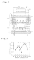
- FIG. 1 is a configuration diagram illustrating a mold 1 for warm working that is used for implementing a warm working method for a stainless steel according to Embodiment 1 of the present invention.
- the mold 1 for warm working is provided with a lower mold 10 and an upper mold 15 disposed such as to sandwich a stainless steel foil 2.
- the lower mold 10 is provided with a bed 11, a punch 12 fixed to the bed 11, and a blank holder 14 that is disposed at the outer circumferential position of the punch 12 and coupled to the bed 11 through a cushion pin 13.
- the upper mold 15 is provided with a slide 16 and a die 18 disposed above the blank holder 14 and fixed to the slide 16 through a spacer 17.
- a servo motor (not shown in the figure) is connected to the slide 16.
- the slide 16, the spacer 17, and the die 18, that is, the upper mold 15, are driven integrally by a drive force from the servo motor in the direction of approaching the lower mold 10 and withdrawing therefrom.
- the upper mold 15 is shifted in the direction approaching the lower mold 10.
- the punch 12 is pressed into the stainless steel foil 2 and the die 18, and the stainless steel foil 2 is subjected to drawing.
- the punch 12 is provided with cooling means constituted by an introduction path 12a connected to an external coolant system (not shown in the figure), a cooling chamber 12b into which a coolant is introduced through the introduction path 12a, and a discharge path 12c through which the coolant is discharged from the cooling chamber 12b.
- the punch 12 can be cooled by introducing the coolant into the cooling chamber 12b.
- the cooling range of the stainless steel foil 2 may include at least the annular region 2a, but may include not only the annular region 2a, but also an inner region of the annular region 2a.
- the present embodiment is configured such that the stainless steel foil 2 is cooled by the punch 12. Therefore, not only the annular region 2a, but also the inner region of the annular region 2a is cooled.
- a counter punch coupled through a spring or the like to the slide can be disposed at a position facing the punch, and a cooling chamber into which the coolant is introduced can be provided in the counter punch, thereby further increasing the cooling efficiency of the stainless steel foil 2 (this configuration is not shown in the figure).
- Heaters 14a, 18a (heating means) for heating the blank holder 14 and the die 18 are incorporated in the blank holder 14 and the die 18. Since the stainless steel foil 2 is sandwiched by the heated blank holder 14 and die 18, the external region 2b of the annular region 2a is heated.
- the stainless steel foil 2 is an uncoated austenitic stainless steel which is not provided with an additional layer, for example such as a resin layer, on the front or rear surface.
- a thin foil with a thickness equal to or less than 300 ⁇ m is used as the stainless steel foil 2.
- a warm working method for the stainless steel foil 2 performed by using the mold 1 for warm working which is depicted in FIG. 1 is described below.
- the stainless steel foil 2 is placed on the punch 12 and the blank holder 14 so as to face the punch 12, and the upper mold 15 is thereafter lowered to a position in which the stainless steel foil 2 is sandwiched between the blank holder 14 and the die 18.
- the punch 12 is disposed at the upper side and the die 18 is disposed at the lower side
- the stainless steel foil 2 is placed on the die 18.
- the annular region 2a of the stainless steel foil 2 is at a temperature of from 0°C to 30°C and the external region 2b of the stainless steel foil 2 is at a temperature of from 40°C to 100°C, preferably from 60°C to 80°C.
- the annular region 2a is set to a temperature of up to 30°C because where the temperature thereof is higher than 30°C, a sufficient increase in breaking strength caused by the martensitic transformation cannot be obtained. Further, the annular region 2a is set to a temperature of 0°C or higher because where the temperature of the annular region is less than 0°C, frost adheres to the punch 12 or the annular region and moldability of the molded product is lost. In addition, the molded article can collapse as a result of temperature-induced shrinkage at the time of removal from the mold.
- the external region 2b is set to a temperature of from 40°C because where the temperature of the external region 2b is less than 40°C, the hardening caused by the martensitic transformation cannot be sufficiently suppressed.
- the external region 2b is set to a temperature of up to 100°C because where the temperature of the external region 2b is higher than 100°C, the temperature of the annular region 2a rises due to a transfer of heat from the external region 2b to the annular region 2a, and a sufficient increase in a breaking strength of the punch caused by the martensitic transformation cannot be obtained.
- working at a larger drawing ratio can be performed by setting the temperature of the external region 2b to from 60°C to 80°C.
- the temperature is set to from 60°C because the effect of suppressing the hardening caused by the martensitic transformation can be demonstrated more reliably, and the temperature is set up to 80°C because the temperature rise of the annular region 2a can be suppressed.
- the temperature of the external region 2b By setting the temperature of the external region 2b to from 40°C to less than 60°C, it is possible to shorten the time required for temperature restoration of the mold 1 for warm working (time required for the temperature of the blank holder 14 and the die 18, which has decreased due to contact with the stainless steel foil 2, to return to a range of from 40°C to less than 60°C) and increase the working efficiency while enabling deep drawing.
- the upper mold 15 is further lowered.
- the punch 12 is pressed into the stainless steel foil 2 and the die 18, drawing is implemented, and the stainless steel foil 2 is molded into a hat shape.
- a lubricating oil is supplied to the punch 12, the die 18, and the stainless steel foil 2 through the entire drawing process.
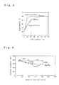
- FIG. 2 is a graph illustrating the difference in a limit drawing ratio caused by the difference in sheet thickness.
- FIG. 3 is a graph illustrating the difference in the increase of temperature caused by the difference in sheet thickness.
- FIG. 4 is a graph illustrating the difference in a tensile strength change caused by the difference in sheet thickness.
- the inventors performed drawing of the stainless steel foil 2 with a thickness of 100 ⁇ m.
- a stainless steel sheet with a thickness of 800 ⁇ m was subjected to drawing.
- the temperature of the external region 2b (the blank holder 14 and the die 18) was changed from 40°C to 120°C while changing the diameter of the stainless steel foil 2 and the stainless steel sheet, and the limit drawing ratio (ratio of the workpiece diameter to the product diameter) at which no cracks occurred was examined.
- the diameter of the punch 12 was 40.0 mm
- the punch shoulder R was 2.5 mm
- the inner diameter of the die 18 was 40.4 mm
- the die shoulder R was 2.0 mm
- the temperature of the annular region 2a (punch 12) was 10°C to 20°C.
- thermal conductivity of a stainless steel foil 2 with a thickness of 100 ⁇ m is higher than that of a stainless steel sheet with a thickness of 800 ⁇ m.
- the heat of the external region 2b is easier transferred to the annular region 2a. Therefore, where the temperature of the external region 2b in a stainless steel foil 2 with a thickness of 100 ⁇ m becomes too high, the temperature of the annular region 2a increases and a sufficient increase in the breaking strength caused by the martensitic transformation cannot be obtained.
- a stainless steel foil 2 with a thickness of 100 ⁇ m is considered, but sufficient deep drawing can be realized in the same temperature region with any stainless steel foil 2 with a thickness equal to or less than 300 ⁇ m. This is because in a stainless steel foil 2 with a thickness equal to or less than 300 ⁇ m, the degree of thermal effect produced on the tensile strength change demonstrates the same trend as in a stainless steel foil 2 with a thickness of 100 ⁇ m. Sufficient deep drawing can also be realized in the same temperature region even with a very thin stainless steel foil 2 with a thickness equal to or less than 5 ⁇ m, provided that such foil can be worked with the mold 1 for warm working.
- a stainless steel foil 2 is subjected to drawing in a state in which the annular region 2a of the stainless steel foil 2 that is in contact with the shoulder portion 12d of the punch 12 is set to a temperature up to 30°C and the external region 2b of the annular region 2a is set to a temperature of from 40°C to 100°C. Therefore, the occurrence of cracking can be suppressed and deep drawing can be realized more reliably even with respect to a thin stainless steel foil with a thickness equal to or less than 300 ⁇ m.
- Such a warm working method is particularly useful, for example, for the production of containers such as battery covers that have to combine high strength with reduced weight.
- the working can be performed at a higher drawing ratio.
- the temperature of the external region 2b is set to from 40°C to less than 60°C when the stainless steel foil 2 is subjected to drawing, it is possible to shorten the time required for temperature restoration of the mold 1 for warm working and increase the working efficiency while realizing deep drawing.
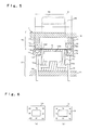
- FIG. 5 is a configuration diagram illustrating the mold 1 for warm working that is used for implementing a warm working method for a stainless steel foil according to Embodiment 2 of the present invention.
- a thermally insulating plate 19 thermally insulating member constituted by glass fibers as a main base material and a borate binder as a main material is provided at the inner circumferential portion of the blank holder 14 facing the outer circumferential surface of the punch 12.
- Other features are the same as in Embodiment 1.
- FIG. 6 is an explanatory drawing illustrating the difference in temperature distribution of the blank holder 14 caused by the presence of the thermally insulating plate 19.
- FIG. 6(a) depicts the temperature distribution obtained when the thermally insulating plate 19 is not provided
- FIG. 6(b) depicts the temperature distribution obtained when the thermally insulating plate 19 is provided.
- FIGS. 6(a) and 6(b) each represent the results obtained by measuring the surface temperature of the blank holder 14 with a contact thermometer after the blank holder was allowed to stay for 30 min at a set temperature of 70°C.
- the working shape was an angular tubular shape with a molding height of 40 mm
- the punch 12 had a shape of 99.64 ⁇ 149.64 mm
- the punch shoulder R was 3.0 mm
- the punch corner R was 4.82 mm
- the die 18 had a shape of 100 ⁇ 150 mm
- the die shoulder R was 3.0 mm
- the die corner R was 5.0 mm.
- Table 1 With thermally insulated structure Without thermally insulated structure Number of times 1 ⁇ ⁇ 2 ⁇ ⁇ 3 ⁇ ⁇ 4 ⁇ ⁇ 5 ⁇ - 6 ⁇ - 7 ⁇ - 8 ⁇ - 9 ⁇ - 10 ⁇ -
- thermally insulating plate 19 is provided at the inner circumferential portion of the blank holder 14, the increase in the temperature of the punch 12 caused by the heat of the blank holder 14 can be avoided and continuous drawing can be performed more reliably in a short interval of time.
Landscapes
- Engineering & Computer Science (AREA)
- Mechanical Engineering (AREA)
- Chemical & Material Sciences (AREA)
- Physics & Mathematics (AREA)
- Thermal Sciences (AREA)
- Materials Engineering (AREA)
- Metallurgy (AREA)
- Organic Chemistry (AREA)
- Shaping Metal By Deep-Drawing, Or The Like (AREA)
Abstract
Description
- The present invention relates to a warm working method for stainless steel foil by which stainless steel foil is subjected to drawing, and also relates to a mold for warm working.
-
Patent Literature 1 listed hereinbelow discloses an example of a conventional warm working method for a stainless steel foil of this type. Thus,Patent Literature 1 describes cooling a punch to 0°C to 30°C and heating a pressure pad to 60°C to 150°C when drawing an austenitic stainless steel sheet with a thickness of about 800 µm to 1000 µm. - Patent Literature 1: Japanese Patent Application Publication No.
2009-113058 - The inventors have investigated the application of the drawing such as described in
Patent Document 1 to a thin stainless steel foil with a thickness equal to or less than 300 µm and encountered the following problem. Namely, the method described inPatent Document 1 is for working a comparatively thick stainless steel sheet with a thickness of about 800 µm to 1000 µm, and when this method is directly applied to a thin stainless steel foil with a thickness equal to or less than 300 µm, cracks occur and deep drawing sometimes cannot be realized. - The present invention has been created to resolve this problem, and it is an objective of the present invention to provide a warm working method for a stainless steel foil that can suppress the occurrence of cracks and can realize deep drawing more reliably even in the case of a thin stainless steel foil with a thickness equal to or less than 300 µm.
- The warm working method for a stainless steel foil according to the present invention includes: disposing an austenitic stainless steel foil with a thickness equal to or less than 300 µm to face a punch and subjecting the stainless steel foil to drawing in a state in which an annular region of the stainless steel foil that is in contact with a shoulder portion of the punch is set to a temperature up to 30°C and an external region outside the annular region is set to a temperature of from 40°C to 100°C.
- A mold for warm working a stainless steel foil in accordance with the present invention includes: a punch; a blank holder disposed at an outer circumferential position of the punch; and a die disposed to face the blank holder, and serves to subject an austenitic stainless steel foil with a thickness equal to or less than 300 µm to drawing by pressing the stainless steel foil together with the punch inward of the die in a state in which the stainless steel foil is interposed between the blank holder and the die, wherein the punch is provided with cooling means; the blank holder and the die are provided with heating means; and the stainless steel foil is subjected to drawing in a state in which an annular region of the stainless steel foil that is in contact with a shoulder portion of the punch is set to a temperature equal to or less than 30°C and an external region outside the annular region interposed between the blank holder and the die is set to a temperature of from 40°C to 100°C.
- With the warm working method for a stainless steel foil in accordance with the present invention, the stainless steel foil is subjected to drawing in a state in which the annular region of the stainless steel foil that is in contact with the shoulder portion of the punch is set to a temperature equal to or less than 30°C and an external region outside the annular region is set to a temperature of from 40°C to 100°C or lower. Therefore, the occurrence of cracks can be suppressed and deep drawing can be realized more reliably even in the case of a thin stainless steel foil with a thickness equal to or less than 300 µm.
-
-
FIG. 1 is a configuration diagram illustrating a mold for warm working that is used for implementing a warm working method for a stainless steel foil according toEmbodiment 1 of the present invention. -
FIG. 2 is a graph illustrating the difference in a limit drawing ratio caused by the difference in a sheet thickness. -
FIG. 3 is a graph illustrating the difference in the increase of temperature caused by the difference in a sheet thickness. -
FIG. 4 is a graph illustrating the difference in a tensile strength change caused by the difference in a sheet thickness. -
FIG. 5 is a configuration diagram illustrating a mold for warm working that is used for implementing a warm working method for a stainless steel foil according toEmbodiment 2 of the present invention. -
FIG. 6 is an explanatory drawing illustrating the difference in temperature distribution of a blank holder caused by the presence of a thermally insulating plate. - Embodiments of the present invention are explained hereinbelow with reference to the appended drawings.
-
FIG. 1 is a configuration diagram illustrating amold 1 for warm working that is used for implementing a warm working method for a stainless steel according toEmbodiment 1 of the present invention. As depicted in the figure, themold 1 for warm working is provided with alower mold 10 and anupper mold 15 disposed such as to sandwich astainless steel foil 2. Thelower mold 10 is provided with a bed 11, apunch 12 fixed to the bed 11, and ablank holder 14 that is disposed at the outer circumferential position of thepunch 12 and coupled to the bed 11 through acushion pin 13. Theupper mold 15 is provided with aslide 16 and adie 18 disposed above theblank holder 14 and fixed to theslide 16 through aspacer 17. - A servo motor (not shown in the figure) is connected to the
slide 16. Theslide 16, thespacer 17, and thedie 18, that is, theupper mold 15, are driven integrally by a drive force from the servo motor in the direction of approaching thelower mold 10 and withdrawing therefrom. After thestainless steel foil 2 has been disposed so as to face thepunch 12, theupper mold 15 is shifted in the direction approaching thelower mold 10. As a result, thepunch 12 is pressed into thestainless steel foil 2 and thedie 18, and thestainless steel foil 2 is subjected to drawing. - The
punch 12 is provided with cooling means constituted by anintroduction path 12a connected to an external coolant system (not shown in the figure), acooling chamber 12b into which a coolant is introduced through theintroduction path 12a, and adischarge path 12c through which the coolant is discharged from thecooling chamber 12b. Thus, thepunch 12 can be cooled by introducing the coolant into thecooling chamber 12b. As a result of bringing such cooledpunch 12 into contact with thestainless steel foil 2, theannular region 2a of thestainless steel foil 2 which is in contact with ashoulder portion 12d of thepunch 12 is cooled. The cooling range of thestainless steel foil 2 may include at least theannular region 2a, but may include not only theannular region 2a, but also an inner region of theannular region 2a. The present embodiment is configured such that thestainless steel foil 2 is cooled by thepunch 12. Therefore, not only theannular region 2a, but also the inner region of theannular region 2a is cooled. - A counter punch coupled through a spring or the like to the slide can be disposed at a position facing the punch, and a cooling chamber into which the coolant is introduced can be provided in the counter punch, thereby further increasing the cooling efficiency of the stainless steel foil 2 (this configuration is not shown in the figure).
-
Heaters blank holder 14 and the die 18 are incorporated in theblank holder 14 and the die 18. Since thestainless steel foil 2 is sandwiched by the heatedblank holder 14 and die 18, theexternal region 2b of theannular region 2a is heated. - The
stainless steel foil 2 is an uncoated austenitic stainless steel which is not provided with an additional layer, for example such as a resin layer, on the front or rear surface. A thin foil with a thickness equal to or less than 300 µm is used as thestainless steel foil 2. - A warm working method for the
stainless steel foil 2 performed by using themold 1 for warm working which is depicted inFIG. 1 is described below. When theupper mold 15 is withdrawn from thelower mold 10, thestainless steel foil 2 is placed on thepunch 12 and theblank holder 14 so as to face thepunch 12, and theupper mold 15 is thereafter lowered to a position in which thestainless steel foil 2 is sandwiched between theblank holder 14 and thedie 18. Where thepunch 12 is disposed at the upper side and the die 18 is disposed at the lower side, thestainless steel foil 2 is placed on the die 18. - In this case, as a result of cooling the
punch 12 and heating theblank holder 14 and thedie 18, theannular region 2a of thestainless steel foil 2 is at a temperature of from 0°C to 30°C and theexternal region 2b of thestainless steel foil 2 is at a temperature of from 40°C to 100°C, preferably from 60°C to 80°C. - The
annular region 2a is set to a temperature of up to 30°C because where the temperature thereof is higher than 30°C, a sufficient increase in breaking strength caused by the martensitic transformation cannot be obtained. Further, theannular region 2a is set to a temperature of 0°C or higher because where the temperature of the annular region is less than 0°C, frost adheres to thepunch 12 or the annular region and moldability of the molded product is lost. In addition, the molded article can collapse as a result of temperature-induced shrinkage at the time of removal from the mold. - The
external region 2b is set to a temperature of from 40°C because where the temperature of theexternal region 2b is less than 40°C, the hardening caused by the martensitic transformation cannot be sufficiently suppressed. Theexternal region 2b is set to a temperature of up to 100°C because where the temperature of theexternal region 2b is higher than 100°C, the temperature of theannular region 2a rises due to a transfer of heat from theexternal region 2b to theannular region 2a, and a sufficient increase in a breaking strength of the punch caused by the martensitic transformation cannot be obtained. - As indicated hereinabove, working at a larger drawing ratio (ratio of the workpiece diameter to the product diameter) can be performed by setting the temperature of the
external region 2b to from 60°C to 80°C. The temperature is set to from 60°C because the effect of suppressing the hardening caused by the martensitic transformation can be demonstrated more reliably, and the temperature is set up to 80°C because the temperature rise of theannular region 2a can be suppressed. - By setting the temperature of the
external region 2b to from 40°C to less than 60°C, it is possible to shorten the time required for temperature restoration of themold 1 for warm working (time required for the temperature of theblank holder 14 and thedie 18, which has decreased due to contact with thestainless steel foil 2, to return to a range of from 40°C to less than 60°C) and increase the working efficiency while enabling deep drawing. - After the temperatures of the
annular region 2a and theexternal region 2b have been set to the above-described temperatures, theupper mold 15 is further lowered. As a result, thepunch 12 is pressed into thestainless steel foil 2 and thedie 18, drawing is implemented, and thestainless steel foil 2 is molded into a hat shape. A lubricating oil is supplied to thepunch 12, thedie 18, and thestainless steel foil 2 through the entire drawing process. -
FIG. 2 is a graph illustrating the difference in a limit drawing ratio caused by the difference in sheet thickness.FIG. 3 is a graph illustrating the difference in the increase of temperature caused by the difference in sheet thickness.FIG. 4 is a graph illustrating the difference in a tensile strength change caused by the difference in sheet thickness. - As an example, the inventors performed drawing of the
stainless steel foil 2 with a thickness of 100 µm. As a comparative example, a stainless steel sheet with a thickness of 800 µm was subjected to drawing. The temperature of theexternal region 2b (theblank holder 14 and the die 18) was changed from 40°C to 120°C while changing the diameter of thestainless steel foil 2 and the stainless steel sheet, and the limit drawing ratio (ratio of the workpiece diameter to the product diameter) at which no cracks occurred was examined. The diameter of thepunch 12 was 40.0 mm, the punch shoulder R was 2.5 mm, the inner diameter of thedie 18 was 40.4 mm, the die shoulder R was 2.0 mm, and the temperature of theannular region 2a (punch 12) was 10°C to 20°C. - As depicted in
FIG. 2 , it was determined that in the case of thestainless steel foil 2 with a thickness of 100 µm, sufficient deep drawing could be realized by setting the temperature of theexternal region 2b to from 40°C to 100°C. In particular, it was determined that drawing at a larger drawing ratio could be performed by setting the temperature of theexternal region 2b to from 60°C to 80°C. - Meanwhile, in the case of the stainless steel plate with a thickness of 800 µm, it was necessary to set the temperature of the
external region 2b to from 80°C to 160°C in order to perform the deep drawing similar to that of the above-describedstainless steel foil 2 with a thickness of 100 µm. Thus, it was determined that the optimum working temperature of thestainless steel foil 2 with a thickness of 100 µm had shifted to the low-temperature side with respect to the optimum working temperature of the stainless steel sheet with a thickness of 800 µm. This comparison confirmed that deep drawing cannot be realized by simple application of the method for working a stainless steel sheet with a thickness of 800 µm to astainless steel foil 2 with a thickness of 100 µm. - The following reason can be suggested for explaining the shift of the optimum working temperature to the low-temperature side. Specifically, as depicted in
FIG. 3 , thermal conductivity of astainless steel foil 2 with a thickness of 100 µm is higher than that of a stainless steel sheet with a thickness of 800 µm. In other words, in astainless steel foil 2 with a thickness of 100 µm, the heat of theexternal region 2b is easier transferred to theannular region 2a. Therefore, where the temperature of theexternal region 2b in astainless steel foil 2 with a thickness of 100 µm becomes too high, the temperature of theannular region 2a increases and a sufficient increase in the breaking strength caused by the martensitic transformation cannot be obtained. As a consequence, the workability of astainless steel foil 2 with a thickness of 100 µm is degraded unless the temperature is lower than that of the stainless steel sheet with a thickness of 800 µm, which is apparently why the optimum working temperature shifts to a low-temperature side. - Further, where the tensile strength change of a
stainless steel foil 2 depicted inFIG. 4 is compared with that of a stainless steel sheet, it can be found that the tensile strength change in a low-temperature region of the stainless steel foil is higher. Therefore, in the case of astainless steel foil 2 with a thickness of 100 µm, a difference in strength similar to that in a stainless steel sheet with a thickness of 800 µm can be obtained at a heating amount which is half or less that in the case of a stainless steel sheet with a thickness of 800 µm. Thus, since astainless steel foil 2 with a thickness of 100 µm can be softened at a temperature lower than that of a stainless steel sheet with a thickness of 800 µm, the optimum working temperature shifts to a low-temperature side. - In the explanation using
FIGS. 2 and3 , astainless steel foil 2 with a thickness of 100 µm is considered, but sufficient deep drawing can be realized in the same temperature region with anystainless steel foil 2 with a thickness equal to or less than 300 µm. This is because in astainless steel foil 2 with a thickness equal to or less than 300 µm, the degree of thermal effect produced on the tensile strength change demonstrates the same trend as in astainless steel foil 2 with a thickness of 100 µm. Sufficient deep drawing can also be realized in the same temperature region even with a very thinstainless steel foil 2 with a thickness equal to or less than 5 µm, provided that such foil can be worked with themold 1 for warm working. - With such a warm working method and
mold 1 for warm working of astainless steel foil 2, astainless steel foil 2 is subjected to drawing in a state in which theannular region 2a of thestainless steel foil 2 that is in contact with theshoulder portion 12d of thepunch 12 is set to a temperature up to 30°C and theexternal region 2b of theannular region 2a is set to a temperature of from 40°C to 100°C. Therefore, the occurrence of cracking can be suppressed and deep drawing can be realized more reliably even with respect to a thin stainless steel foil with a thickness equal to or less than 300 µm. Such a warm working method is particularly useful, for example, for the production of containers such as battery covers that have to combine high strength with reduced weight. - Further, where the temperature of the
external region 2b is set to from 60°C to 80°C when thestainless steel foil 2 is subjected to drawing, the working can be performed at a higher drawing ratio. - Furthermore, where the temperature of the
external region 2b is set to from 40°C to less than 60°C when thestainless steel foil 2 is subjected to drawing, it is possible to shorten the time required for temperature restoration of themold 1 for warm working and increase the working efficiency while realizing deep drawing. -
FIG. 5 is a configuration diagram illustrating themold 1 for warm working that is used for implementing a warm working method for a stainless steel foil according toEmbodiment 2 of the present invention. As depicted inFIG. 5 , in themold 1 for warm working according toEmbodiment 2, a thermally insulating plate 19 (thermally insulating member) constituted by glass fibers as a main base material and a borate binder as a main material is provided at the inner circumferential portion of theblank holder 14 facing the outer circumferential surface of thepunch 12. Other features are the same as inEmbodiment 1. -
FIG. 6 is an explanatory drawing illustrating the difference in temperature distribution of theblank holder 14 caused by the presence of the thermally insulatingplate 19. Thus,FIG. 6(a) depicts the temperature distribution obtained when the thermally insulatingplate 19 is not provided, andFIG. 6(b) depicts the temperature distribution obtained when the thermally insulatingplate 19 is provided.FIGS. 6(a) and 6(b) each represent the results obtained by measuring the surface temperature of theblank holder 14 with a contact thermometer after the blank holder was allowed to stay for 30 min at a set temperature of 70°C. - In the configuration which is not provided with the thermally insulating
plate 19, as depicted inFIG. 6(a) , the deviation of the surface temperature of theblank holder 14 reaches 30°C at maximum. A low temperature in the upper portion depicted in the figure is due to the presence of a lead-out portion of a control thermocouple orheater 14a in this portion. Meanwhile, in the configuration which is provided with the thermally insulatingplate 19 at the inner circumferential portion ofblank holder 14, as depicted inFIG. 6(b) , the temperature distribution is greatly reduced. This is apparently because the presence of the thermally insulatingplate 19 at the inner circumferential portion prevents the heat of theheater 14a from escaping to the central hole (hole for inserting the punch 12) of theblank holder 14 and the heat of theheater 14a spreads uniformly over the entireblank holder 14. This temperature distribution indicates that the heat of theblank holder 14 is unlikely to be transferred to thepunch 12 due to the presence of the thermally insulatingplate 19 at the inner circumferential portion of theblank holder 14. - An example is explained hereinbelow. The inventors continuously implemented at 30-sec intervals the drawing of stainless steel foils 2 with a thickness of 100 µm by using the
mold 1 for warm working (with the thermally insulated structure) depicted inFIG. 5 and themold 1 for warm working (without a thermally insulated structure) depicted inFIG. 1 . In the continuous drawing, the set temperature of theexternal region 2b (blank holder 14 and die 18) was 70°C and the set temperature of theannular region 2a (punch 12) was 10°C to 20°C. The possibility of continuous press working was then investigated. The results are shown in Table 1 below. - The working shape was an angular tubular shape with a molding height of 40 mm, the
punch 12 had a shape of 99.64 × 149.64 mm, the punch shoulder R was 3.0 mm, the punch corner R was 4.82 mm, the die 18 had a shape of 100 × 150 mm, the die shoulder R was 3.0 mm, and the die corner R was 5.0 mm.Table 1 With thermally insulated structure Without thermally insulated structure Number of times 1 ○ ○ 2 ○ ○ 3 ○ ○ 4 ○ × 5 ○ - 6 ○ - 7 ○ - 8 ○ - 9 ○ - 10 ○ - - As shown in Table 1, where the results of continuous press working obtained with the
mold 1 for warm working (with a thermally insulated structure) depicted inFIG. 5 and themold 1 for warm working (without a thermally insulated structure) depicted inFIG. 1 are compared, the number of possible continuous pressing operations with the former mold is larger than that with the latter mold. This is apparently because the presence of the thermally insulatingplate 19 on the inner circumferential portion of theblank holder 14 makes it possible to avoid increases in the temperature of thepunch 12 caused by the heat of theblank holder 14 and maintain a more adequate relationship between the temperatures of theannular region 2a and theexternal region 2b. When the temperature of thepunch 12 was measured before and after the continuous pressing, the temperature change was less and the temperature was more stable with themold 1 for warm working (with a thermally insulated structure) depicted inFIG. 5 . - With such warm working method and
mold 1 for warm working of thestainless steel foil 2, since the thermally insulatingplate 19 is provided at the inner circumferential portion of theblank holder 14, the increase in the temperature of thepunch 12 caused by the heat of theblank holder 14 can be avoided and continuous drawing can be performed more reliably in a short interval of time.
Claims (6)
- A warm working method for a stainless steel foil, the method comprising: disposing an austenitic stainless steel foil with a thickness equal to or less than 300 µm to face a punch, and subjecting the stainless steel foil to drawing in a state in which an annular region of the stainless steel foil that is in contact with a shoulder portion of the punch is set to a temperature up to 30°C and an external region outside the annular region is set to a temperature of from 40°C to 100°C.
- The warm working method for a stainless steel foil according to claim 1, wherein the temperature of the external region is set to from 60°C to 80°C when the stainless steel foil is subjected to drawing.
- The warm working method for a stainless steel foil according to claim 1, wherein the temperature of the external region is set to from 40°C to less than 60°C when the stainless steel foil is subjected to drawing.
- The warm working method for a stainless steel foil according to any one of claims 1 to 3, further comprising restricting the external region by using a blank holder disposed at an outer circumferential position of the punch, wherein
a heater for heating the external region is provided inside the blank holder; and
a thermally insulating member is provided at an inner circumferential portion of the blank holder facing the outer circumferential surface of the punch. - A mold for warm working a stainless steel foil,
the mold comprising:a punch;a blank holder disposed at an outer circumferential position of the punch; anda die disposed to face the blank holder, and wherethe mold serving to subject an austenitic stainless steel foil with a thickness equal to or less than 300 µm to drawing by pressing the stainless steel foil together with the punch inward of the die in a state in which the stainless steel foil is interposed between the blank holder and the die, whereinthe punch is provided with cooling means,the blank holder and the die are provided with heating means, andthe stainless steel foil is subjected to drawing in a state in which an annular region of the stainless steel foil that is in contact with a shoulder portion of the punch is set to a temperature equal up to 30°C and an external region outside the annular region interposed between the blank holder and the die is set to a temperature of from 40°C to 100°C. - The mold for warm working a stainless steel foil according to claim 5, wherein
a thermally insulating member is provided at an inner circumferential portion of the blank holder facing the outer circumferential surface of the punch.
Applications Claiming Priority (3)
| Application Number | Priority Date | Filing Date | Title |
|---|---|---|---|
| JP2012215865 | 2012-09-28 | ||
| JP2013198203A JP5699193B2 (en) | 2012-09-28 | 2013-09-25 | Stainless steel foil warm working method and warm working mold |
| PCT/JP2013/076028 WO2014050955A1 (en) | 2012-09-28 | 2013-09-26 | Method for warm working stainless steel foil and mold for warm working |
Publications (3)
| Publication Number | Publication Date |
|---|---|
| EP2902131A1 true EP2902131A1 (en) | 2015-08-05 |
| EP2902131A4 EP2902131A4 (en) | 2016-06-08 |
| EP2902131B1 EP2902131B1 (en) | 2020-04-15 |
Family
ID=50388350
Family Applications (1)
| Application Number | Title | Priority Date | Filing Date |
|---|---|---|---|
| EP13842476.7A Active EP2902131B1 (en) | 2012-09-28 | 2013-09-26 | Method for warm working stainless steel foil |
Country Status (7)
| Country | Link |
|---|---|
| US (2) | US9802238B2 (en) |
| EP (1) | EP2902131B1 (en) |
| JP (1) | JP5699193B2 (en) |
| KR (1) | KR101912987B1 (en) |
| CN (1) | CN104684662B (en) |
| CA (1) | CA2885913C (en) |
| WO (1) | WO2014050955A1 (en) |
Families Citing this family (6)
| Publication number | Priority date | Publication date | Assignee | Title |
|---|---|---|---|---|
| US10590615B2 (en) * | 2016-06-28 | 2020-03-17 | Vigor Industrial Llc | Orthotropic deck |
| EP3540381B1 (en) * | 2018-03-16 | 2020-02-19 | Siemens Aktiengesellschaft | Flow measurement in valves with thermal correction |
| CN109807231A (en) * | 2019-02-14 | 2019-05-28 | 桐乡市佑泰新材料有限公司 | A kind of alloy foil impact forming method |
| KR102929919B1 (en) | 2020-09-25 | 2026-02-24 | 주식회사 엘지에너지솔루션 | Pouch-type battery case forming apparatus comprising volatile lubricant supply unit and method of manufacturing pouch-type battery case using the same |
| CN113579070B (en) * | 2021-06-16 | 2023-04-04 | 江苏凯撒型材科技有限公司 | Take stamping device of photovoltaic module steel frame's of protection cornerite angle sign indicating number |
| CN119133423A (en) * | 2024-08-29 | 2024-12-13 | 浙江锂威能源科技有限公司 | Metal lithium material, method for controlling metal lithium crystal plane orientation, pole piece and battery |
Family Cites Families (10)
| Publication number | Priority date | Publication date | Assignee | Title |
|---|---|---|---|---|
| JPS5927261B2 (en) * | 1978-04-28 | 1984-07-04 | 川崎製鉄株式会社 | Ultra-deep drawing method for ferrite stainless steel |
| JPH01118320A (en) * | 1987-10-30 | 1989-05-10 | Tsuinbaade Kogyo Kk | Manufacture of stainless container for electric pot |
| JPH05237558A (en) * | 1992-02-28 | 1993-09-17 | Furukawa Alum Co Ltd | Warm deep drawing forming method |
| JPH11309519A (en) * | 1998-04-24 | 1999-11-09 | Kawasaki Steel Corp | High speed deep drawing method for polygonal cylinder case made of stainless steel |
| JP2005205416A (en) | 2004-01-20 | 2005-08-04 | Nissan Motor Co Ltd | Hot press molding method and hot press mold |
| JP2009113058A (en) * | 2007-11-02 | 2009-05-28 | Advan Eng Kk | Method of forming austenitic stainless steel rectangular tube container, forming apparatus and rectangular tube container |
| CN101791649A (en) * | 2010-03-04 | 2010-08-04 | 刘江 | Die for differential-temperature drawing and straightening processing |
| CN201711425U (en) * | 2010-03-04 | 2011-01-19 | 刘江 | Die for producing ultra-thin cylinder with thickness below 0.1 mm |
| JP5675681B2 (en) * | 2011-03-29 | 2015-02-25 | 日新製鋼株式会社 | Manufacturing method of exterior material of laminated battery |
| CN102886422B (en) * | 2012-10-22 | 2015-02-25 | 安徽工业大学 | Punching method for improving flanging capability of sheet |
-
2013
- 2013-09-25 JP JP2013198203A patent/JP5699193B2/en active Active
- 2013-09-26 CA CA2885913A patent/CA2885913C/en active Active
- 2013-09-26 WO PCT/JP2013/076028 patent/WO2014050955A1/en not_active Ceased
- 2013-09-26 CN CN201380050840.2A patent/CN104684662B/en active Active
- 2013-09-26 US US14/431,665 patent/US9802238B2/en active Active
- 2013-09-26 KR KR1020157010091A patent/KR101912987B1/en active Active
- 2013-09-26 EP EP13842476.7A patent/EP2902131B1/en active Active
-
2016
- 2016-10-12 US US15/291,177 patent/US9815103B2/en active Active
Also Published As
| Publication number | Publication date |
|---|---|
| CA2885913A1 (en) | 2014-04-03 |
| EP2902131B1 (en) | 2020-04-15 |
| JP2014079806A (en) | 2014-05-08 |
| US20170028456A1 (en) | 2017-02-02 |
| KR101912987B1 (en) | 2018-10-29 |
| US20150231683A1 (en) | 2015-08-20 |
| JP5699193B2 (en) | 2015-04-08 |
| KR20150060797A (en) | 2015-06-03 |
| US9815103B2 (en) | 2017-11-14 |
| CN104684662B (en) | 2017-08-15 |
| CA2885913C (en) | 2019-07-16 |
| WO2014050955A1 (en) | 2014-04-03 |
| US9802238B2 (en) | 2017-10-31 |
| EP2902131A4 (en) | 2016-06-08 |
| CN104684662A (en) | 2015-06-03 |
Similar Documents
| Publication | Publication Date | Title |
|---|---|---|
| US9815103B2 (en) | Warm working method for stainless steel foil and mold for warm working | |
| JP5808724B2 (en) | Die quench apparatus and die quench method for aluminum alloy material | |
| KR101868402B1 (en) | Partial softening hot stamping and trimming method | |
| CN108237155A (en) | A kind of complex-curved manufacturing method of large size tokamak vacuum room housing | |
| EP3865227B1 (en) | Method for manufacturing a press-molded article, a retainer, and a manufacturing system for a press-molded article | |
| CN103443955B (en) | Manufacturing method of cover member of laminated battery | |
| JP5266676B2 (en) | Warm forming method and molded product produced by the warm forming method | |
| KR101721034B1 (en) | Fe-alloy powder for forming a 3D-printed layer | |
| KR20150051014A (en) | Apparatus for warm press and method having the same | |
| US8343393B2 (en) | Molding method and apparatus for an optical element | |
| WO2014050166A1 (en) | Method for warm working stainless steel foil | |
| JP6018469B2 (en) | Stainless steel foil warm working method | |
| KR101344963B1 (en) | Hot forming and variable thickness stamping | |
| JP7675353B2 (en) | Mold for molding glass and molding method for glass product | |
| CN109895440A (en) | The pressurizing device of air hermetic continuous hot-press molding machine | |
| JP2014069202A (en) | Method for warm working plated steel foil | |
| US20090120535A1 (en) | Method of bonding steel members, method of enhancing bonding strength of united body formed of steel members, steel product, and die-cast product | |
| JP2007223875A (en) | Mold, mold assembly including the same, and manufacturing method thereof | |
| JP5751386B2 (en) | Glass product manufacturing method and glass product manufacturing apparatus | |
| JP5984442B2 (en) | Press mold for glass molding and method for manufacturing the same | |
| JP2012158490A (en) | Apparatus and method for manufacturing optical element | |
| JPH04224119A (en) | Method for forming optical element | |
| KR20170053195A (en) | Manufacturing method and appratus for formed plate | |
| JP2007112638A (en) | Optical element manufacturing apparatus and manufacturing method | |
| JPH0497917A (en) | Method for forming optical element and its transmissible optical element |
Legal Events
| Date | Code | Title | Description |
|---|---|---|---|
| PUAI | Public reference made under article 153(3) epc to a published international application that has entered the european phase |
Free format text: ORIGINAL CODE: 0009012 |
|
| 17P | Request for examination filed |
Effective date: 20150304 |
|
| AK | Designated contracting states |
Kind code of ref document: A1 Designated state(s): AL AT BE BG CH CY CZ DE DK EE ES FI FR GB GR HR HU IE IS IT LI LT LU LV MC MK MT NL NO PL PT RO RS SE SI SK SM TR |
|
| AX | Request for extension of the european patent |
Extension state: BA ME |
|
| DAX | Request for extension of the european patent (deleted) | ||
| RA4 | Supplementary search report drawn up and despatched (corrected) |
Effective date: 20160506 |
|
| RIC1 | Information provided on ipc code assigned before grant |
Ipc: B21D 24/16 20060101ALI20160429BHEP Ipc: B21D 37/16 20060101ALI20160429BHEP Ipc: B21D 33/00 20060101AFI20160429BHEP Ipc: B21D 22/20 20060101ALI20160429BHEP |
|
| STAA | Information on the status of an ep patent application or granted ep patent |
Free format text: STATUS: EXAMINATION IS IN PROGRESS |
|
| 17Q | First examination report despatched |
Effective date: 20190606 |
|
| RAP1 | Party data changed (applicant data changed or rights of an application transferred) |
Owner name: NIPPON STEEL NISSHIN CO., LTD. |
|
| GRAP | Despatch of communication of intention to grant a patent |
Free format text: ORIGINAL CODE: EPIDOSNIGR1 |
|
| STAA | Information on the status of an ep patent application or granted ep patent |
Free format text: STATUS: GRANT OF PATENT IS INTENDED |
|
| INTG | Intention to grant announced |
Effective date: 20191128 |
|
| GRAS | Grant fee paid |
Free format text: ORIGINAL CODE: EPIDOSNIGR3 |
|
| GRAA | (expected) grant |
Free format text: ORIGINAL CODE: 0009210 |
|
| STAA | Information on the status of an ep patent application or granted ep patent |
Free format text: STATUS: THE PATENT HAS BEEN GRANTED |
|
| AK | Designated contracting states |
Kind code of ref document: B1 Designated state(s): AL AT BE BG CH CY CZ DE DK EE ES FI FR GB GR HR HU IE IS IT LI LT LU LV MC MK MT NL NO PL PT RO RS SE SI SK SM TR |
|
| REG | Reference to a national code |
Ref country code: CH Ref legal event code: EP |
|
| REG | Reference to a national code |
Ref country code: DE Ref legal event code: R096 Ref document number: 602013068027 Country of ref document: DE |
|
| REG | Reference to a national code |
Ref country code: IE Ref legal event code: FG4D |
|
| REG | Reference to a national code |
Ref country code: AT Ref legal event code: REF Ref document number: 1256649 Country of ref document: AT Kind code of ref document: T Effective date: 20200515 |
|
| REG | Reference to a national code |
Ref country code: NL Ref legal event code: MP Effective date: 20200415 |
|
| REG | Reference to a national code |
Ref country code: LT Ref legal event code: MG4D |
|
| PG25 | Lapsed in a contracting state [announced via postgrant information from national office to epo] |
Ref country code: GR Free format text: LAPSE BECAUSE OF FAILURE TO SUBMIT A TRANSLATION OF THE DESCRIPTION OR TO PAY THE FEE WITHIN THE PRESCRIBED TIME-LIMIT Effective date: 20200716 Ref country code: NO Free format text: LAPSE BECAUSE OF FAILURE TO SUBMIT A TRANSLATION OF THE DESCRIPTION OR TO PAY THE FEE WITHIN THE PRESCRIBED TIME-LIMIT Effective date: 20200715 Ref country code: IS Free format text: LAPSE BECAUSE OF FAILURE TO SUBMIT A TRANSLATION OF THE DESCRIPTION OR TO PAY THE FEE WITHIN THE PRESCRIBED TIME-LIMIT Effective date: 20200815 Ref country code: FI Free format text: LAPSE BECAUSE OF FAILURE TO SUBMIT A TRANSLATION OF THE DESCRIPTION OR TO PAY THE FEE WITHIN THE PRESCRIBED TIME-LIMIT Effective date: 20200415 Ref country code: NL Free format text: LAPSE BECAUSE OF FAILURE TO SUBMIT A TRANSLATION OF THE DESCRIPTION OR TO PAY THE FEE WITHIN THE PRESCRIBED TIME-LIMIT Effective date: 20200415 Ref country code: PT Free format text: LAPSE BECAUSE OF FAILURE TO SUBMIT A TRANSLATION OF THE DESCRIPTION OR TO PAY THE FEE WITHIN THE PRESCRIBED TIME-LIMIT Effective date: 20200817 Ref country code: SE Free format text: LAPSE BECAUSE OF FAILURE TO SUBMIT A TRANSLATION OF THE DESCRIPTION OR TO PAY THE FEE WITHIN THE PRESCRIBED TIME-LIMIT Effective date: 20200415 Ref country code: LT Free format text: LAPSE BECAUSE OF FAILURE TO SUBMIT A TRANSLATION OF THE DESCRIPTION OR TO PAY THE FEE WITHIN THE PRESCRIBED TIME-LIMIT Effective date: 20200415 |
|
| REG | Reference to a national code |
Ref country code: AT Ref legal event code: MK05 Ref document number: 1256649 Country of ref document: AT Kind code of ref document: T Effective date: 20200415 |
|
| PG25 | Lapsed in a contracting state [announced via postgrant information from national office to epo] |
Ref country code: HR Free format text: LAPSE BECAUSE OF FAILURE TO SUBMIT A TRANSLATION OF THE DESCRIPTION OR TO PAY THE FEE WITHIN THE PRESCRIBED TIME-LIMIT Effective date: 20200415 Ref country code: BG Free format text: LAPSE BECAUSE OF FAILURE TO SUBMIT A TRANSLATION OF THE DESCRIPTION OR TO PAY THE FEE WITHIN THE PRESCRIBED TIME-LIMIT Effective date: 20200715 Ref country code: RS Free format text: LAPSE BECAUSE OF FAILURE TO SUBMIT A TRANSLATION OF THE DESCRIPTION OR TO PAY THE FEE WITHIN THE PRESCRIBED TIME-LIMIT Effective date: 20200415 Ref country code: LV Free format text: LAPSE BECAUSE OF FAILURE TO SUBMIT A TRANSLATION OF THE DESCRIPTION OR TO PAY THE FEE WITHIN THE PRESCRIBED TIME-LIMIT Effective date: 20200415 |
|
| PG25 | Lapsed in a contracting state [announced via postgrant information from national office to epo] |
Ref country code: AL Free format text: LAPSE BECAUSE OF FAILURE TO SUBMIT A TRANSLATION OF THE DESCRIPTION OR TO PAY THE FEE WITHIN THE PRESCRIBED TIME-LIMIT Effective date: 20200415 |
|
| REG | Reference to a national code |
Ref country code: DE Ref legal event code: R097 Ref document number: 602013068027 Country of ref document: DE |
|
| PG25 | Lapsed in a contracting state [announced via postgrant information from national office to epo] |
Ref country code: ES Free format text: LAPSE BECAUSE OF FAILURE TO SUBMIT A TRANSLATION OF THE DESCRIPTION OR TO PAY THE FEE WITHIN THE PRESCRIBED TIME-LIMIT Effective date: 20200415 Ref country code: DK Free format text: LAPSE BECAUSE OF FAILURE TO SUBMIT A TRANSLATION OF THE DESCRIPTION OR TO PAY THE FEE WITHIN THE PRESCRIBED TIME-LIMIT Effective date: 20200415 Ref country code: AT Free format text: LAPSE BECAUSE OF FAILURE TO SUBMIT A TRANSLATION OF THE DESCRIPTION OR TO PAY THE FEE WITHIN THE PRESCRIBED TIME-LIMIT Effective date: 20200415 Ref country code: EE Free format text: LAPSE BECAUSE OF FAILURE TO SUBMIT A TRANSLATION OF THE DESCRIPTION OR TO PAY THE FEE WITHIN THE PRESCRIBED TIME-LIMIT Effective date: 20200415 Ref country code: SM Free format text: LAPSE BECAUSE OF FAILURE TO SUBMIT A TRANSLATION OF THE DESCRIPTION OR TO PAY THE FEE WITHIN THE PRESCRIBED TIME-LIMIT Effective date: 20200415 Ref country code: IT Free format text: LAPSE BECAUSE OF FAILURE TO SUBMIT A TRANSLATION OF THE DESCRIPTION OR TO PAY THE FEE WITHIN THE PRESCRIBED TIME-LIMIT Effective date: 20200415 Ref country code: RO Free format text: LAPSE BECAUSE OF FAILURE TO SUBMIT A TRANSLATION OF THE DESCRIPTION OR TO PAY THE FEE WITHIN THE PRESCRIBED TIME-LIMIT Effective date: 20200415 Ref country code: CZ Free format text: LAPSE BECAUSE OF FAILURE TO SUBMIT A TRANSLATION OF THE DESCRIPTION OR TO PAY THE FEE WITHIN THE PRESCRIBED TIME-LIMIT Effective date: 20200415 |
|
| PLBE | No opposition filed within time limit |
Free format text: ORIGINAL CODE: 0009261 |
|
| STAA | Information on the status of an ep patent application or granted ep patent |
Free format text: STATUS: NO OPPOSITION FILED WITHIN TIME LIMIT |
|
| PG25 | Lapsed in a contracting state [announced via postgrant information from national office to epo] |
Ref country code: PL Free format text: LAPSE BECAUSE OF FAILURE TO SUBMIT A TRANSLATION OF THE DESCRIPTION OR TO PAY THE FEE WITHIN THE PRESCRIBED TIME-LIMIT Effective date: 20200415 Ref country code: SK Free format text: LAPSE BECAUSE OF FAILURE TO SUBMIT A TRANSLATION OF THE DESCRIPTION OR TO PAY THE FEE WITHIN THE PRESCRIBED TIME-LIMIT Effective date: 20200415 |
|
| 26N | No opposition filed |
Effective date: 20210118 |
|
| REG | Reference to a national code |
Ref country code: DE Ref legal event code: R119 Ref document number: 602013068027 Country of ref document: DE |
|
| PG25 | Lapsed in a contracting state [announced via postgrant information from national office to epo] |
Ref country code: MC Free format text: LAPSE BECAUSE OF FAILURE TO SUBMIT A TRANSLATION OF THE DESCRIPTION OR TO PAY THE FEE WITHIN THE PRESCRIBED TIME-LIMIT Effective date: 20200415 |
|
| REG | Reference to a national code |
Ref country code: CH Ref legal event code: PL |
|
| GBPC | Gb: european patent ceased through non-payment of renewal fee |
Effective date: 20200926 |
|
| PG25 | Lapsed in a contracting state [announced via postgrant information from national office to epo] |
Ref country code: SI Free format text: LAPSE BECAUSE OF FAILURE TO SUBMIT A TRANSLATION OF THE DESCRIPTION OR TO PAY THE FEE WITHIN THE PRESCRIBED TIME-LIMIT Effective date: 20200415 |
|
| REG | Reference to a national code |
Ref country code: BE Ref legal event code: MM Effective date: 20200930 |
|
| PG25 | Lapsed in a contracting state [announced via postgrant information from national office to epo] |
Ref country code: LU Free format text: LAPSE BECAUSE OF NON-PAYMENT OF DUE FEES Effective date: 20200926 |
|
| PG25 | Lapsed in a contracting state [announced via postgrant information from national office to epo] |
Ref country code: FR Free format text: LAPSE BECAUSE OF NON-PAYMENT OF DUE FEES Effective date: 20200930 Ref country code: DE Free format text: LAPSE BECAUSE OF NON-PAYMENT OF DUE FEES Effective date: 20210401 |
|
| PG25 | Lapsed in a contracting state [announced via postgrant information from national office to epo] |
Ref country code: LI Free format text: LAPSE BECAUSE OF NON-PAYMENT OF DUE FEES Effective date: 20200930 Ref country code: GB Free format text: LAPSE BECAUSE OF NON-PAYMENT OF DUE FEES Effective date: 20200926 Ref country code: IE Free format text: LAPSE BECAUSE OF NON-PAYMENT OF DUE FEES Effective date: 20200926 Ref country code: BE Free format text: LAPSE BECAUSE OF NON-PAYMENT OF DUE FEES Effective date: 20200930 Ref country code: CH Free format text: LAPSE BECAUSE OF NON-PAYMENT OF DUE FEES Effective date: 20200930 |
|
| PG25 | Lapsed in a contracting state [announced via postgrant information from national office to epo] |
Ref country code: TR Free format text: LAPSE BECAUSE OF FAILURE TO SUBMIT A TRANSLATION OF THE DESCRIPTION OR TO PAY THE FEE WITHIN THE PRESCRIBED TIME-LIMIT Effective date: 20200415 Ref country code: MT Free format text: LAPSE BECAUSE OF FAILURE TO SUBMIT A TRANSLATION OF THE DESCRIPTION OR TO PAY THE FEE WITHIN THE PRESCRIBED TIME-LIMIT Effective date: 20200415 Ref country code: CY Free format text: LAPSE BECAUSE OF FAILURE TO SUBMIT A TRANSLATION OF THE DESCRIPTION OR TO PAY THE FEE WITHIN THE PRESCRIBED TIME-LIMIT Effective date: 20200415 |
|
| PG25 | Lapsed in a contracting state [announced via postgrant information from national office to epo] |
Ref country code: MK Free format text: LAPSE BECAUSE OF FAILURE TO SUBMIT A TRANSLATION OF THE DESCRIPTION OR TO PAY THE FEE WITHIN THE PRESCRIBED TIME-LIMIT Effective date: 20200415 |