EP2902088A1 - Carbon dioxide capturing apparatus - Google Patents
Carbon dioxide capturing apparatus Download PDFInfo
- Publication number
- EP2902088A1 EP2902088A1 EP13841840.5A EP13841840A EP2902088A1 EP 2902088 A1 EP2902088 A1 EP 2902088A1 EP 13841840 A EP13841840 A EP 13841840A EP 2902088 A1 EP2902088 A1 EP 2902088A1
- Authority
- EP
- European Patent Office
- Prior art keywords
- carbon dioxide
- adsorption
- desorption
- section
- fluidized bed
- Prior art date
- Legal status (The legal status is an assumption and is not a legal conclusion. Google has not performed a legal analysis and makes no representation as to the accuracy of the status listed.)
- Granted
Links
Images





Classifications
-
- B—PERFORMING OPERATIONS; TRANSPORTING
- B01—PHYSICAL OR CHEMICAL PROCESSES OR APPARATUS IN GENERAL
- B01D—SEPARATION
- B01D53/00—Separation of gases or vapours; Recovering vapours of volatile solvents from gases; Chemical or biological purification of waste gases, e.g. engine exhaust gases, smoke, fumes, flue gases, aerosols
- B01D53/02—Separation of gases or vapours; Recovering vapours of volatile solvents from gases; Chemical or biological purification of waste gases, e.g. engine exhaust gases, smoke, fumes, flue gases, aerosols by adsorption, e.g. preparative gas chromatography
- B01D53/06—Separation of gases or vapours; Recovering vapours of volatile solvents from gases; Chemical or biological purification of waste gases, e.g. engine exhaust gases, smoke, fumes, flue gases, aerosols by adsorption, e.g. preparative gas chromatography with moving adsorbents, e.g. rotating beds
- B01D53/10—Separation of gases or vapours; Recovering vapours of volatile solvents from gases; Chemical or biological purification of waste gases, e.g. engine exhaust gases, smoke, fumes, flue gases, aerosols by adsorption, e.g. preparative gas chromatography with moving adsorbents, e.g. rotating beds with dispersed adsorbents
- B01D53/12—Separation of gases or vapours; Recovering vapours of volatile solvents from gases; Chemical or biological purification of waste gases, e.g. engine exhaust gases, smoke, fumes, flue gases, aerosols by adsorption, e.g. preparative gas chromatography with moving adsorbents, e.g. rotating beds with dispersed adsorbents according to the "fluidised technique"
-
- B—PERFORMING OPERATIONS; TRANSPORTING
- B01—PHYSICAL OR CHEMICAL PROCESSES OR APPARATUS IN GENERAL
- B01D—SEPARATION
- B01D53/00—Separation of gases or vapours; Recovering vapours of volatile solvents from gases; Chemical or biological purification of waste gases, e.g. engine exhaust gases, smoke, fumes, flue gases, aerosols
- B01D53/02—Separation of gases or vapours; Recovering vapours of volatile solvents from gases; Chemical or biological purification of waste gases, e.g. engine exhaust gases, smoke, fumes, flue gases, aerosols by adsorption, e.g. preparative gas chromatography
- B01D53/04—Separation of gases or vapours; Recovering vapours of volatile solvents from gases; Chemical or biological purification of waste gases, e.g. engine exhaust gases, smoke, fumes, flue gases, aerosols by adsorption, e.g. preparative gas chromatography with stationary adsorbents
- B01D53/0462—Temperature swing adsorption
-
- B—PERFORMING OPERATIONS; TRANSPORTING
- B01—PHYSICAL OR CHEMICAL PROCESSES OR APPARATUS IN GENERAL
- B01D—SEPARATION
- B01D53/00—Separation of gases or vapours; Recovering vapours of volatile solvents from gases; Chemical or biological purification of waste gases, e.g. engine exhaust gases, smoke, fumes, flue gases, aerosols
- B01D53/02—Separation of gases or vapours; Recovering vapours of volatile solvents from gases; Chemical or biological purification of waste gases, e.g. engine exhaust gases, smoke, fumes, flue gases, aerosols by adsorption, e.g. preparative gas chromatography
- B01D53/06—Separation of gases or vapours; Recovering vapours of volatile solvents from gases; Chemical or biological purification of waste gases, e.g. engine exhaust gases, smoke, fumes, flue gases, aerosols by adsorption, e.g. preparative gas chromatography with moving adsorbents, e.g. rotating beds
- B01D53/08—Separation of gases or vapours; Recovering vapours of volatile solvents from gases; Chemical or biological purification of waste gases, e.g. engine exhaust gases, smoke, fumes, flue gases, aerosols by adsorption, e.g. preparative gas chromatography with moving adsorbents, e.g. rotating beds according to the "moving bed" method
-
- B—PERFORMING OPERATIONS; TRANSPORTING
- B01—PHYSICAL OR CHEMICAL PROCESSES OR APPARATUS IN GENERAL
- B01D—SEPARATION
- B01D53/00—Separation of gases or vapours; Recovering vapours of volatile solvents from gases; Chemical or biological purification of waste gases, e.g. engine exhaust gases, smoke, fumes, flue gases, aerosols
- B01D53/34—Chemical or biological purification of waste gases
- B01D53/46—Removing components of defined structure
- B01D53/62—Carbon oxides
-
- B—PERFORMING OPERATIONS; TRANSPORTING
- B01—PHYSICAL OR CHEMICAL PROCESSES OR APPARATUS IN GENERAL
- B01D—SEPARATION
- B01D53/00—Separation of gases or vapours; Recovering vapours of volatile solvents from gases; Chemical or biological purification of waste gases, e.g. engine exhaust gases, smoke, fumes, flue gases, aerosols
- B01D53/34—Chemical or biological purification of waste gases
- B01D53/74—General processes for purification of waste gases; Apparatus or devices specially adapted therefor
- B01D53/75—Multi-step processes
-
- B—PERFORMING OPERATIONS; TRANSPORTING
- B01—PHYSICAL OR CHEMICAL PROCESSES OR APPARATUS IN GENERAL
- B01D—SEPARATION
- B01D53/00—Separation of gases or vapours; Recovering vapours of volatile solvents from gases; Chemical or biological purification of waste gases, e.g. engine exhaust gases, smoke, fumes, flue gases, aerosols
- B01D53/34—Chemical or biological purification of waste gases
- B01D53/74—General processes for purification of waste gases; Apparatus or devices specially adapted therefor
- B01D53/81—Solid phase processes
- B01D53/83—Solid phase processes with moving reactants
-
- B—PERFORMING OPERATIONS; TRANSPORTING
- B01—PHYSICAL OR CHEMICAL PROCESSES OR APPARATUS IN GENERAL
- B01D—SEPARATION
- B01D53/00—Separation of gases or vapours; Recovering vapours of volatile solvents from gases; Chemical or biological purification of waste gases, e.g. engine exhaust gases, smoke, fumes, flue gases, aerosols
- B01D53/34—Chemical or biological purification of waste gases
- B01D53/96—Regeneration, reactivation or recycling of reactants
-
- B—PERFORMING OPERATIONS; TRANSPORTING
- B04—CENTRIFUGAL APPARATUS OR MACHINES FOR CARRYING-OUT PHYSICAL OR CHEMICAL PROCESSES
- B04C—APPARATUS USING FREE VORTEX FLOW, e.g. CYCLONES
- B04C7/00—Apparatus not provided for in group B04C1/00, B04C3/00, or B04C5/00; Multiple arrangements not provided for in one of the groups B04C1/00, B04C3/00, or B04C5/00; Combinations of apparatus covered by two or more of the groups B04C1/00, B04C3/00, or B04C5/00
-
- B—PERFORMING OPERATIONS; TRANSPORTING
- B01—PHYSICAL OR CHEMICAL PROCESSES OR APPARATUS IN GENERAL
- B01D—SEPARATION
- B01D2251/00—Reactants
- B01D2251/30—Alkali metal compounds
-
- B—PERFORMING OPERATIONS; TRANSPORTING
- B01—PHYSICAL OR CHEMICAL PROCESSES OR APPARATUS IN GENERAL
- B01D—SEPARATION
- B01D2251/00—Reactants
- B01D2251/40—Alkaline earth metal or magnesium compounds
-
- B—PERFORMING OPERATIONS; TRANSPORTING
- B01—PHYSICAL OR CHEMICAL PROCESSES OR APPARATUS IN GENERAL
- B01D—SEPARATION
- B01D2253/00—Adsorbents used in seperation treatment of gases and vapours
- B01D2253/10—Inorganic adsorbents
- B01D2253/106—Silica or silicates
- B01D2253/108—Zeolites
-
- B—PERFORMING OPERATIONS; TRANSPORTING
- B01—PHYSICAL OR CHEMICAL PROCESSES OR APPARATUS IN GENERAL
- B01D—SEPARATION
- B01D2257/00—Components to be removed
- B01D2257/50—Carbon oxides
- B01D2257/504—Carbon dioxide
-
- B—PERFORMING OPERATIONS; TRANSPORTING
- B01—PHYSICAL OR CHEMICAL PROCESSES OR APPARATUS IN GENERAL
- B01D—SEPARATION
- B01D2258/00—Sources of waste gases
- B01D2258/02—Other waste gases
- B01D2258/025—Other waste gases from metallurgy plants
-
- B—PERFORMING OPERATIONS; TRANSPORTING
- B01—PHYSICAL OR CHEMICAL PROCESSES OR APPARATUS IN GENERAL
- B01D—SEPARATION
- B01D2258/00—Sources of waste gases
- B01D2258/02—Other waste gases
- B01D2258/0283—Flue gases
-
- B—PERFORMING OPERATIONS; TRANSPORTING
- B01—PHYSICAL OR CHEMICAL PROCESSES OR APPARATUS IN GENERAL
- B01D—SEPARATION
- B01D2259/00—Type of treatment
- B01D2259/65—Employing advanced heat integration, e.g. Pinch technology
-
- Y—GENERAL TAGGING OF NEW TECHNOLOGICAL DEVELOPMENTS; GENERAL TAGGING OF CROSS-SECTIONAL TECHNOLOGIES SPANNING OVER SEVERAL SECTIONS OF THE IPC; TECHNICAL SUBJECTS COVERED BY FORMER USPC CROSS-REFERENCE ART COLLECTIONS [XRACs] AND DIGESTS
- Y02—TECHNOLOGIES OR APPLICATIONS FOR MITIGATION OR ADAPTATION AGAINST CLIMATE CHANGE
- Y02A—TECHNOLOGIES FOR ADAPTATION TO CLIMATE CHANGE
- Y02A50/00—TECHNOLOGIES FOR ADAPTATION TO CLIMATE CHANGE in human health protection, e.g. against extreme weather
- Y02A50/20—Air quality improvement or preservation, e.g. vehicle emission control or emission reduction by using catalytic converters
-
- Y—GENERAL TAGGING OF NEW TECHNOLOGICAL DEVELOPMENTS; GENERAL TAGGING OF CROSS-SECTIONAL TECHNOLOGIES SPANNING OVER SEVERAL SECTIONS OF THE IPC; TECHNICAL SUBJECTS COVERED BY FORMER USPC CROSS-REFERENCE ART COLLECTIONS [XRACs] AND DIGESTS
- Y02—TECHNOLOGIES OR APPLICATIONS FOR MITIGATION OR ADAPTATION AGAINST CLIMATE CHANGE
- Y02C—CAPTURE, STORAGE, SEQUESTRATION OR DISPOSAL OF GREENHOUSE GASES [GHG]
- Y02C20/00—Capture or disposal of greenhouse gases
- Y02C20/40—Capture or disposal of greenhouse gases of CO2
Definitions
- the present invention relates to carbon dioxide capture systems, and more specifically to carbon dioxide capture systems that prevent carbon dioxide present in flue gases from industrial facilities, such as power plants and steel mills, from being exhausted into the atmosphere.
- CCS carbon capture and storage
- the carbon dioxide capture techniques can be divided into post-combustion capture, pre-combustion capture, and oxy-fuel capture according to stages at which carbon dioxide is captured.
- the carbon dioxide capture techniques can also be divided into membrane separation, liquid phase separation, and solid phase separation techniques according to the principles of carbon dioxide capture.
- the membrane separation techniques use separation membranes to concentrate carbon dioxide
- the liquid phase separation techniques use liquid adsorbents such as amines or aqueous ammonia
- the solid phase separation techniques use solid phase adsorbents such as alkali or alkaline earth metals.
- Solid phase separation techniques are largely directed towards the development of solid phase adsorbents Carbon dioxide capture efficiency is greatly affected by the design of adsorption processes as well as the performance of solid phase adsorbents.
- Solid phase adsorbents can be broadly classified into organic, inorganic, carbon-based, and organic-inorganic hybrid adsorbents by the kind of their constituent materials.
- Solid phase adsorbents can also be classified into physical adsorbents and chemical adsorbents depending on their forms adsorbed by carbon dioxide.
- Such solid phase adsorbents include: amine polymer adsorbents as organic adsorbents; zeolite-based adsorbents, alkali adsorbents, and alkaline earth metal adsorbents as inorganic adsorbents; activated carbon adsorbents modified with alkali metals as carbon-based adsorbents; and MOF adsorbents and porous silica adsorbents grafted with organic materials having an amine group as organic-inorganic hybrid adsorbents.
- Carbon dioxide is physically adsorbed to zeolite-based and carbon-based adsorbents.
- Carbon dioxide is adsorbed to the other adsorbents through chemical reactions ( Energy Environ. Sci. 2011, 4, 42 . ChemSusChem 2009, 2, 796 ).
- Solid phase separation includes the steps of adsorbing carbon dioxide to a target object, and desorbing and separating the adsorbed carbon dioxide from the target object.
- the adsorption and desorption of carbon dioxide may occur reversibly and may be induced through heat exchange or a change in external pressure.
- Such carbon dioxide capture processes using dry adsorbents are classified into pressure swing adsorption (PSA) processes and temperature swing adsorption (TSA) processes by the factors they use.
- PSA pressure swing adsorption
- TSA temperature swing adsorption
- pressure swing adsorption processes using fixed bed adsorption columns are advantageous in capturing carbon dioxide on a small scale
- an easy-to-scale-up temperature swing adsorption processes using fluidized bed adsorption and desorption columns are advantageous in capturing a large amount of carbon dioxide from power plants or large combustion furnaces.
- the present invention is intended to capture a large amount of carbon dioxide in a continuous manner using solid adsorbents and is based on a temperature swing adsorption process using fluidized bed adsorption columns and fluidized bed desorption columns.
- the adsorption columns and desorption columns can be divided into bubbling fluidized bed columns and diluted fluidized bed columns according to the concentration of adsorbents in operating regions.
- Adsorbents are present at high concentrations in the bubbling fluidized bed columns and at low concentrations in the diluted fluidized bed columns.
- bubbling fluidized beds and diluted fluidized beds to adsorption columns and desorption columns provides four possible combinations: i) diluted fluidized bed columns-diluted fluidized bed columns, ii) diluted fluidized bed columns-bubbling fluidized bed columns, iii) bubbling fluidized bed columns-diluted fluidized bed columns, and iv) bubbling fluidized bed columns-bubbling fluidized bed columns (" Fluidization Engineering", D. Kunii and O. Levenspiel, Robert E. Krieger, 1977 ).
- Korean Patent Publication Nos. 2005-0003767 , 2010-0099929 , and 2011-0054948 disclose fluidized bed processes for carbon dioxide capture that use dry solid adsorbents based on the concept of temperature swing adsorption using diluted fluidized bed adsorption columns and bubbling fluidized bed desorption columns. According to such solid phase separation processes based on the concept of temperature swing adsorption, however, a vast amount of energy of at least 2 GJ/t-CO 2 is consumed to desorb carbon dioxide from adsorbents. This energy consumption is a cause of increased capture cost, together with the cost of the adsorbents. Thus, it is very important to develop a technology by which carbon dioxide can be effectively desorbed from adsorbents with less energy, achieving reduced capture cost.
- a first object of the present invention is to provide a multi-stage carbon dioxide capture system constructed to use carbon dioxide adsorbents having different adsorption and desorption temperatures so that heat of carbon dioxide adsorption can be used for the desorption of carbon dioxide.
- a second object of the present invention is to provide a carbon dioxide capture system constructed to use heat generated from carbon dioxide adsorption for the desorption of the adsorbed carbon dioxide so that the amount of energy consumed to capture carbon dioxide can be reduced.
- a third object of the present invention is to provide a carbon dioxide capture system constructed to use adsorbents having low carbon dioxide adsorption and desorption rates, achieving efficient heat exchange.
- a fourth object of the present invention is to provide a carbon dioxide capture system constructed to use adsorbents having a low carbon dioxide adsorption rate and a high carbon dioxide desorption rate, achieving efficient heat exchange.
- a fifth object of the present invention is to provide a carbon dioxide capture system constructed to use adsorbents having a high carbon dioxide adsorption rate and a low carbon dioxide desorption rate, achieving efficient heat exchange.
- a sixth object of the present invention is to provide a carbon dioxide capture system constructed to use adsorbents having high carbon dioxide adsorption and desorption rates, achieving efficient heat exchange.
- a seventh object of the present invention is to provide a carbon dioxide capture method using carbon dioxide adsorbents having different carbon dioxide adsorption and desorption temperatures to achieve improved process efficiency.
- a carbon dioxide capture system for selective separation of carbon dioxide from flue gases, including: a first carbon dioxide adsorption/desorption section including a first carbon dioxide adsorption section, a first carbon dioxide desorption section connected to the first carbon dioxide adsorption section, and a first carbon dioxide adsorbent circulating through the first carbon dioxide adsorption section and the first carbon dioxide desorption section; and a second carbon dioxide adsorption/desorption section including a second carbon dioxide adsorption section, a second carbon dioxide desorption section connected to the second carbon dioxide adsorption section, and a second carbon dioxide adsorbent circulating through the second carbon dioxide adsorption section and the second carbon dioxide desorption section, wherein the first carbon dioxide adsorption section is connected to the second carbon dioxide desorption section such that adsorption heat generated from the first carbon dioxide adsorption section is transferred to the second carbon dioxide desorption section, and the first carbon dioxide adsorbent has different adsorption
- the first carbon dioxide adsorption section may be connected to the second carbon dioxide desorption section in such a manner that the first carbon dioxide adsorption section penetrates the second carbon dioxide desorption section or the second carbon dioxide desorption section penetrates the first carbon dioxide adsorption section.
- the first carbon dioxide adsorption section may be connected to the second carbon dioxide desorption section through a heat transfer medium.
- the first carbon dioxide desorption section is preferably designed such that the first carbon dioxide desorption section is filled with 0.1 to 10% by volume of the first carbon dioxide adsorbent.
- the first carbon dioxide desorption section is preferably designed such that the first carbon dioxide desorption section is filled with 10 to 80% by volume of the first carbon dioxide adsorbent.
- the second carbon dioxide adsorption section is preferably designed such that the second carbon dioxide adsorption section is filled with 0.1 to 10% by volume of the second carbon dioxide adsorbent.
- the second carbon dioxide adsorption section is preferably designed such that the second carbon dioxide adsorption section is filled with 10 to 80% by volume of the second carbon dioxide adsorbent.
- a carbon dioxide capture system for selective separation of carbon dioxide from flue gases, including a plurality of carbon dioxide adsorption/desorption sections in which carbon dioxide adsorbents are filled and carbon dioxide is continuously adsorbed and desorbed while the carbon dioxide adsorbents circulate through carbon dioxide adsorption and desorption regions, wherein adsorption heat generated from the carbon dioxide adsorption region of at least one of the carbon dioxide adsorption/desorption sections is transferred to the carbon dioxide desorption region of the adjacent adsorption/desorption section, and at least one of the adsorbents filled in the carbon dioxide adsorption/desorption sections has different carbon dioxide adsorption and desorption temperatures from the other adsorbent(s).
- adsorption heat generated from the carbon dioxide adsorption region of at least one of the carbon dioxide adsorption/desorption sections may be transferred to the carbon dioxide desorption region of the adjacent adsorption/desorption section in such a manner that the carbon dioxide adsorption region comes into direct contact with the carbon dioxide desorption region.
- adsorption heat generated from the carbon dioxide adsorption region of at least one of the carbon dioxide adsorption/desorption sections may be transferred to the carbon dioxide desorption region of the adjacent adsorption/desorption section through a heat transfer medium.
- a heat exchanger may be provided between the carbon dioxide adsorption region and the carbon dioxide desorption region.
- the plurality of carbon dioxide adsorption/desorption sections are divided into a high temperature carbon dioxide adsorption/desorption section, an intermediate temperature carbon dioxide adsorption/desorption section, and a low temperature carbon dioxide adsorption/desorption section; adsorption heat generated from a carbon dioxide adsorption region of the high temperature carbon dioxide adsorption/desorption section may be transferred to a carbon dioxide desorption region of the intermediate temperature carbon dioxide adsorption/desorption section; and adsorption heat generated from a carbon dioxide adsorption region of the intermediate temperature carbon dioxide adsorption/desorption section may be transferred to a carbon dioxide desorption region of the low temperature carbon dioxide adsorption/desorption section.
- a carbon dioxide capture system including a plurality of carbon dioxide adsorption/desorption sections, each of which includes: a bubbling fluidized bed adsorption column in which a carbon dioxide adsorbent is moved from the top to the bottom; a bubbling fluidized bed desorption column in which a carbon dioxide adsorbent is moved from the top to the bottom; a first connection line connecting the bottom of the bubbling fluidized bed adsorption column to the top of the bubbling fluidized bed desorption column; a second connection line connecting the bottom of the bubbling fluidized bed desorption column to the top of the bubbling fluidized bed adsorption column; and a cyclone disposed between the second connection line and the bubbling fluidized bed adsorption column, wherein at least one of the plurality of carbon dioxide adsorption/desorption sections is constructed such that heat is exchangeable.
- a carbon dioxide capture system including a plurality of carbon dioxide adsorption/desorption sections, each of which includes: a bubbling fluidized bed adsorption column in which a carbon dioxide adsorbent is moved from the top to the bottom; a diluted fluidized bed desorption column in which a carbon dioxide adsorbent is moved from the bottom to the top; and a cyclone disposed between the bubbling fluidized bed adsorption column and the diluted fluidized bed desorption column, wherein at least one of the plurality of carbon dioxide adsorption/desorption sections is constructed such that heat is exchangeable.
- a carbon dioxide capture system including a plurality of carbon dioxide adsorption/desorption sections, each of which includes: a diluted fluidized bed adsorption column in which a carbon dioxide adsorbent is moved from the bottom to the top; a bubbling fluidized bed desorption column in which a carbon dioxide adsorbent is moved from the top to the bottom; and a cyclone disposed between the diluted fluidized bed adsorption column and the bubbling fluidized bed desorption column, wherein at least one of the plurality of carbon dioxide adsorption/desorption sections is constructed such that heat is exchangeable.
- a carbon dioxide capture system including a plurality of carbon dioxide adsorption/desorption sections, each of which includes: a diluted fluidized bed adsorption column in which a carbon dioxide adsorbent is moved from the bottom to the top; a diluted fluidized bed desorption column in which a carbon dioxide adsorbent is moved from the bottom to the top; two storage columns connecting the diluted fluidized bed adsorption column to the diluted fluidized bed desorption column; a cyclone disposed between the diluted fluidized bed adsorption column and one of the storage columns; and a cyclone disposed between the diluted fluidized bed desorption column and the other storage column, wherein at least one of the plurality of carbon dioxide adsorption/desorption sections is constructed such that heat is exchangeable.
- a carbon dioxide capture method for selective separation of carbon dioxide from flue gases wherein carbon dioxide is adsorbed and desorbed in a plurality of carbon dioxide adsorption/desorption sections, and at least one of the plurality of carbon dioxide adsorption/desorption sections uses a carbon dioxide adsorbent having different carbon dioxide adsorption and desorption temperatures from a carbon dioxide adsorbent used in the adjacent carbon dioxide adsorption/desorption section.
- the plurality of carbon dioxide adsorption/desorption sections may be connected to each other such that heat is exchangeable.
- the adsorption and desorption temperatures of carbon dioxide in at least one of the plurality of carbon dioxide adsorption/desorption sections are different from those of carbon dioxide in the adjacent carbon dioxide adsorption/desorption section.
- the carbon dioxide capture systems according to the embodiments of the present invention have the following advantageous effects.
- One embodiment of the present invention provides a carbon dioxide capture system including: a first carbon dioxide adsorption/desorption section including a first carbon dioxide adsorption section, a first carbon dioxide desorption section connected to the first carbon dioxide adsorption section, and a first carbon dioxide adsorbent circulating through the first carbon dioxide adsorption section and the first carbon dioxide desorption section; and a second carbon dioxide adsorption/desorption section including a second carbon dioxide adsorption section, a second carbon dioxide desorption section connected to the second carbon dioxide adsorption section, and a second carbon dioxide adsorbent circulating through the second carbon dioxide adsorption section and the second carbon dioxide desorption section, wherein the first carbon dioxide adsorption section is connected to the second carbon dioxide desorption section such that adsorption heat generated from the first carbon dioxide adsorption section is transferred to the second carbon dioxide desorption section, and the first carbon dioxide adsorbent has different adsorption and desorption temperatures from the second carbon dioxide adsorbent.
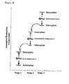
- FIG. 1 is a diagram for explaining the concept of using heat of carbon dioxide adsorption as heat necessary for the desorption of carbon dioxide in a carbon dioxide adsorption-desorption cycle consisting of a low temperature region, an intermediate temperature region, and high temperature region in accordance with one embodiment of the present invention.
- carbon dioxide adsorption/desorption sections in which carbon dioxide is adsorbed and desorbed at different temperatures are multi-stage connected. This connection enables the transfer of energy between the carbon dioxide adsorption/desorption sections where carbon dioxide is adsorbed and desorbed.
- adsorbents having different adsorption and desorption temperatures are filled in the high temperature, intermediate temperature, and low temperature carbon dioxide adsorption/desorption sections, adsorption heat is generated in the course of desorbing adsorbed carbon dioxide and is transferred to the adjacent region to induce the desorption of carbon dioxide or reduce the amount of heat necessary for desorption.
- adsorption heat is emitted when the adsorbent adsorbs carbon dioxide in the high temperature region and is used as energy necessary for the adsorbent in the intermediate temperature region to desorb the carbon dioxide
- adsorption heat is emitted when the adsorbent adsorbs carbon dioxide in the intermediate temperature region and is used as energy necessary for the adsorbent in the low temperature region to desorb the carbon dioxide.
- the use of energy generated during adsorption of carbon dioxide as energy necessary for the desorption of carbon dioxide can reduce the cost of energy consumed to desorb the carbon dioxide.
- carbon dioxide capture systems may be designed to have various constructions.
- the carbon dioxide capture systems may be constructed to include bubbling fluidized bed or diluted fluidized bed carbon dioxide adsorption sections and bubbling fluidized bed or diluted fluidized bed desorption sections. That is, the following four possible combinations are possible: i) bubbling fluidized bed adsorption sections-bubbling fluidized bed adsorption sections, ii) bubbling fluidized bed adsorption sections-diluted fluidized bed desorption sections, iii) diluted fluidized bed adsorption sections-bubbling fluidized bed desorption sections, and iv) diluted fluidized bed adsorption sections-diluted fluidized bed desorption sections.
- Each of the bubbling fluidized bed adsorption sections or desorption sections is designed such that it is preferably filled with an adsorbent at a concentration of 10 to 80% by volume, more preferably 30 to 60% by volume.
- Each of the diluted fluidized bed adsorption sections or desorption sections is designed such that it is preferably filled with an adsorbent at a concentration of 0.1 to 10% by volume, more preferably 0.5 to 5% by volume.
- the carbon dioxide capture systems are required to have constructions specially designed to use heat of carbon dioxide adsorption for the desorption of carbon dioxide.
- Methods for transferring heat of carbon dioxide adsorption to the adjacent carbon dioxide desorption section may also be modified.
- One of the modified methods is to exchange heat in a state in which the carbon dioxide adsorption section is in direct contact with the carbon dioxide desorption section.
- Another modified method is to exchange heat using a heat transfer medium.
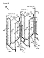
- FIG. 2 illustrates main parts of a carbon dioxide capture system including bubbling fluidized bed adsorption columns and bubbling fluidized bed desorption columns according to one embodiment of the present invention.
- the carbon dioxide capture system includes carbon dioxide adsorption/desorption sections, which may be connected in three stages, i.e. low, intermediate, and high temperature stages.
- An adsorbent in the intermediate temperature region generates heat by adsorption of carbon dioxide. This heat is transferred to the low temperature region by direct heat exchange through the wall of the reactor and is used as energy necessary for the desorption of carbon dioxide in the low temperature region.
- An adsorbent in the high temperature region generates heat by adsorption of carbon dioxide.
- This heat is transferred to the intermediate temperature region by direct heat exchange through the wall of the reactor and is used as energy necessary for the desorption of carbon dioxide in the intermediate temperature region. That is, adsorption heat generated during adsorption of carbon dioxide in the higher temperature region is sequentially transferred to the lower temperature region where the adsorption heat is used as energy necessary for the desorption of the adsorbed carbon dioxide.
- each of the carbon dioxide adsorption/desorption section in the low temperature cycle region and the carbon dioxide adsorption/desorption section in the high temperature cycle region of the bubbling fluidized bed-bubbling fluidized bed carbon dioxide capture system 100 includes a bubbling fluidized bed carbon dioxide adsorption section 101, a bubbling fluidized bed carbon dioxide desorption section 102, cyclones 103 and 104, a heat exchanger 105, a first transfer line 106, and a second transfer line 107.
- the carbon dioxide adsorption/desorption section in the low temperature cycle region is filled with a carbon dioxide adsorbent having relatively low carbon dioxide adsorption and desorption temperatures
- the carbon dioxide adsorption/desorption section in the high temperature cycle region is filled with a carbon dioxide adsorbent having relatively high carbon dioxide adsorption and desorption temperatures.
- a flue gas containing carbon dioxide is supplied to the bottom of each bubbling fluidized bed carbon dioxide adsorption section 101, and the flue gas free from carbon dioxide is released through the cyclone 103 disposed on the top of the bubbling fluidized bed carbon dioxide adsorption section 101.
- Carbon dioxide is adsorbed to the carbon dioxide adsorbent in the bubbling fluidized bed carbon dioxide adsorption section 101.
- the carbon dioxide adsorbent After adsorption, the carbon dioxide adsorbent is moved in the direction from the top to the bottom in the bubbling fluidized bed carbon dioxide adsorption section 101 and is supplied to the top of the bubbling fluidized bed carbon dioxide desorption section 102 through the first transfer line 106. Carbon dioxide is desorbed in the bubbling fluidized bed carbon dioxide desorption section 102 and is released through the cyclone 104. After desorption, the adsorbent is transferred from the bottom of the bubbling fluidized bed carbon dioxide desorption section 102 to the top of the bubbling fluidized bed carbon dioxide adsorption section 101 through the second transfer line 107. As this cycle is repeated, carbon dioxide can be captured from the flue gases and released to the outside.
- the carbon dioxide adsorption section and the carbon dioxide desorption section are connected adjacent to each other and are arranged such that heat is exchangeable therebetween.
- the figure illustrates that the carbon dioxide adsorption section is arranged so as to penetrate the carbon dioxide desorption section.
- the adsorption section may be connected to the desorption section through a wall.
- Cooling means may be placed in the bubbling fluidized bed carbon dioxide adsorption section 101 and heating means may be placed in the bubbling fluidized bed carbon dioxide desorption section 102.
- the carbon dioxide adsorbent entering the bubbling fluidized bed carbon dioxide adsorption section 101 may be precooled and the carbon dioxide adsorbent entering the bubbling fluidized bed carbon dioxide desorption section 102 may be preheated.
- the heat exchanger 105 may be used for the precooling and preheating.
- at least one heat exchanger may be further installed at a necessary location.
- at least one compressor or blower may be provided to move the carbon dioxide adsorbent, if needed.
- the carbon dioxide capture system including the bubbling fluidized bed adsorption sections and the bubbling fluidized bed desorption sections is constructed to sufficiently maintain the retention of the adsorbents in the adsorption sections and the desorption sections for a time necessary to adsorb and desorb carbon dioxide.
- the transfer lines are used for sufficient retention of the adsorbents. This construction is advantageous when the adsorbents for carbon dioxide capture have low adsorption and desorption rates.
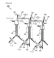
- FIG. 3 illustrates main parts of a carbon dioxide capture system including bubbling fluidized bed adsorption columns and diluted fluidized bed desorption columns according to one embodiment of the present invention.
- the carbon dioxide capture system includes carbon adsorption/desorption sections, which may be connected in three stages, i.e. low, intermediate, and high temperature stages. Due to this connection, heat of carbon dioxide adsorption may be transferred from the high temperature region to the intermediate temperature region and from the intermediate temperature region to the low temperature region.
- each of the carbon dioxide adsorption/desorption section in the low temperature cycle region and the carbon dioxide adsorption/desorption section in the high temperature cycle region of the bubbling fluidized bed-diluted fluidized bed carbon dioxide capture system 200 includes a bubbling fluidized bed carbon dioxide adsorption section 201, a diluted fluidized bed carbon dioxide desorption section 202, a cyclone 203, and a heat exchanger 205.
- a flue gas containing carbon dioxide is supplied to the bottom of each bubbling fluidized bed carbon dioxide adsorption section 201, and the flue gas free from carbon dioxide is released from the top of the bubbling fluidized bed carbon dioxide adsorption section 201.
- Carbon dioxide is adsorbed to a carbon dioxide adsorbent in the bubbling fluidized bed carbon dioxide adsorption section 201. After adsorption, the carbon dioxide adsorbent is moved in the direction from the top to the bottom in the bubbling fluidized bed carbon dioxide adsorption section 201 and is supplied to the bottom of the diluted fluidized bed carbon dioxide desorption section 202. While the carbon dioxide adsorbent entering the diluted fluidized bed carbon dioxide desorption section 202 is moved from the bottom to the top, carbon dioxide is desorbed from the carbon dioxide adsorbent. The desorbed carbon dioxide is released through the cyclone 203 and the carbon dioxide adsorbent is again supplied to the top of the bubbling fluidized bed carbon dioxide adsorption section 201.
- the carbon dioxide adsorption section and the carbon dioxide desorption section are connected adjacent to each other and are arranged such that heat is exchangeable therebetween.
- the fluidized bed carbon dioxide desorption section 202 is arranged so as to penetrate the bubbling fluidized bed carbon dioxide adsorption section 201 and heat is exchanged through the wall.
- the adsorption section may be connected to the desorption section through a wall.
- Cooling means may be placed in the bubbling fluidized bed carbon dioxide adsorption section 201 and heating means may be placed in the diluted fluidized bed carbon dioxide desorption section 202.
- Preheating or precooling means may be further provided to preheat or precool the carbon dioxide adsorbent.
- At least one compressor or blower may be further provided to move the carbon dioxide adsorbent.
- the carbon dioxide capture system including the bubbling fluidized bed adsorption sections and the diluted fluidized bed desorption sections is constructed to sufficiently maintain the retention of the adsorbents in the adsorption sections for a time necessary to adsorb carbon dioxide.
- the retention time of the adsorbents in the carbon dioxide desorption sections may be determined depending on the operating conditions of the system. This construction is advantageous when the adsorbents have a low carbon dioxide adsorption rate and a high carbon dioxide desorption rate.
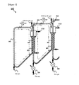
- FIG. 4 illustrates main parts of a carbon dioxide capture system including diluted fluidized bed adsorption columns and bubbling fluidized bed desorption columns according to one embodiment of the present invention.
- the carbon dioxide capture system includes carbon dioxide adsorption/desorption sections, which may be connected in three stages, i.e. low, intermediate, and high temperature stages. Due to this connection, heat of carbon dioxide adsorption may be transferred from the high temperature region to the intermediate temperature region and from the intermediate temperature region to the low temperature region.
- each of the carbon dioxide adsorption/desorption section in the low temperature cycle region and the carbon dioxide adsorption/desorption section in the high temperature cycle region of the diluted fluidized bed-bubbling fluidized bed carbon dioxide capture system 300 includes a diluted fluidized bed carbon dioxide adsorption section 301, a bubbling fluidized bed carbon dioxide desorption section 302, a cyclone 303, and a heat exchanger 305.
- a flue gas containing carbon dioxide is supplied to the bottom of each diluted fluidized bed carbon dioxide adsorption section 301, and the flue gas free from carbon dioxide is released through the cyclone 303 disposed on the diluted fluidized bed carbon dioxide adsorption section 301.
- Carbon dioxide is adsorbed to a carbon dioxide adsorbent in the diluted fluidized bed carbon dioxide adsorption section 301. After adsorption, the carbon dioxide adsorbent is moved in the direction from the bottom to the top in the diluted fluidized bed carbon dioxide adsorption section 301 and is supplied to the top of the bubbling fluidized bed carbon dioxide desorption section 302. While the carbon dioxide adsorbent entering the bubbling fluidized bed carbon dioxide desorption section 302 is moved in the direction from the top to the bottom, carbon dioxide is desorbed from the carbon dioxide adsorbent.
- the carbon dioxide adsorption section and the carbon dioxide desorption section are connected adjacent to each other and are arranged such that heat is exchangeable therebetween.
- the diluted fluidized bed carbon dioxide adsorption section 301 is arranged so as to penetrate the bubbling fluidized bed carbon dioxide desorption section 302 and heat is exchanged through the wall.
- the adsorption section may be connected to the desorption section through a wall.
- Cooling means may be placed in the diluted fluidized bed carbon dioxide adsorption section 301 and heating means may be placed in the bubbling fluidized bed carbon dioxide desorption section 302.
- Preheating or precooling means may be further provided to preheat or precool the carbon dioxide adsorbent.
- At least one compressor or blower may be further provided to move the carbon dioxide adsorbent.
- the retention time of the adsorbents in the carbon dioxide desorption sections of the carbon dioxide capture system may be determined depending on the operating conditions of the system. This construction is advantageous when the adsorbents have a high carbon dioxide adsorption rate and a low carbon dioxide desorption rate.
- FIG. 5 illustrates main parts of a carbon dioxide capture system including diluted fluidized bed adsorption columns and diluted fluidized bed desorption columns according to one embodiment of the present invention.
- the carbon dioxide capture system includes carbon dioxide adsorption/desorption sections, which may be connected in three stages, i.e. low, intermediate, and high temperature stages. Due to this connection, heat of carbon dioxide adsorption may be transferred from the high temperature region to the intermediate temperature region and from the intermediate temperature region to the low temperature region.
- each of the carbon dioxide adsorption/desorption section in the low temperature cycle region and the carbon dioxide adsorption/desorption section in the high temperature cycle region of the diluted fluidized bed-diluted fluidized bed carbon dioxide capture system 400 includes a diluted fluidized bed carbon dioxide adsorption section 401, a diluted fluidized bed carbon dioxide desorption section 402, cyclones 403 and 404, a heat exchanger 405, and storage columns 406 and 407.
- a flue gas containing carbon dioxide is supplied to the bottom of each diluted fluidized bed carbon dioxide adsorption section 401, and the flue gas free from carbon dioxide is released through the cyclone 403 disposed on the diluted fluidized bed carbon dioxide adsorption section 401.
- Carbon dioxide is adsorbed to a carbon dioxide adsorbent in the diluted fluidized bed carbon dioxide adsorption section 401. After adsorption, the carbon dioxide adsorbent is moved in the direction from the bottom to the top in the diluted fluidized bed carbon dioxide adsorption section 401 and is subsequently supplied to the top of the storage column 406 and the bottom of the diluted fluidized bed carbon dioxide desorption section 402. While the carbon dioxide adsorbent entering the diluted fluidized bed carbon dioxide desorption section 402 is moved in the direction from the bottom to the top, carbon dioxide is desorbed from the carbon dioxide adsorbent and is released through the cyclone 404.
- the carbon dioxide adsorbent is supplied to the bottom of the diluted fluidized bed carbon dioxide adsorption section 401 through the storage column 407. Since the carbon dioxide adsorbents are moved in the direction from the bottom to the top in both the adsorption section and the desorption section, spaces are required to accommodate the adsorbents separated from the cyclones.
- the storage columns 406 and 407 function as means for accommodating the adsorbents.
- the carbon dioxide adsorption section and the carbon dioxide desorption section are connected adjacent to each other and are arranged such that heat is exchangeable therebetween.
- the diluted fluidized bed carbon dioxide adsorption section 401 is arranged so as to penetrate the diluted fluidized bed carbon dioxide desorption section 402 and heat is exchanged through the wall.
- any arrangement is also possible so long as heat can be directly exchanged between the adsorption section and the desorption section.
- the adsorption section may be connected to the desorption section through a wall.
- Cooling means may be placed in the diluted fluidized bed carbon dioxide adsorption section 401 and heating means may be placed in the diluted fluidized bed carbon dioxide desorption section 402.
- Preheating or precooling means may be further provided to preheat or precool the carbon dioxide adsorbent.
- At least one compressor or blower may be further provided to move the carbon dioxide adsorbent.
- the retention time of the adsorbents in the carbon dioxide adsorption sections and desorption sections of the carbon dioxide capture system may be determined depending on the operating conditions of the system. This construction is advantageous when the adsorbents have high adsorption and desorption rates.
- FIG. 6 is a diagram for explaining the concept of transferring heat of carbon dioxide adsorption to a region necessary for the desorption of carbon dioxide through a heat transfer medium in accordance with one embodiment of the present invention.
- the carbon dioxide capture system 500 includes diluted fluidized bed carbon dioxide adsorption sections 501, bubbling fluidized bed carbon dioxide desorption sections 502, and a heat transfer medium 503.
- the heat transfer medium 503 connects the carbon dioxide adsorption section 501 to the bubbling fluidized bed carbon dioxide desorption section 502 and functions as a medium to transfer heat of carbon dioxide adsorption to the desorption section.
- the transfer of heat through the heat transfer medium enables free design of the parts of the system, thus being advantageous in simplifying or scaling-up the construction of the system.
- the heat transfer medium is composed of a material having a high thermal conductivity.
- the system may include heat insulating means surrounding the outer surface thereof.
- the heat insulating means may be, for example, a heat insulating water jacket or silicone oil jacket.
- the carbon dioxide capture system of FIG. 6 including the diluted fluidized bed carbon dioxide adsorption sections and the bubbling fluidized bed carbon dioxide desorption sections is exemplified for ease of explanation.
- the heat transfer medium may also be applied to other carbon dioxide capture systems.
- FIGS. 7 to 11 A detailed description will be given concerning the constructions and operations of the carbon dioxide capture systems with reference to FIGS. 7 to 11 . These figures explain the embodiments of the present invention and some of the parts may be omitted or modified depending on the characteristics of the carbon dioxide adsorbents and the operating conditions of the systems.
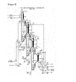
- FIGS. 7 to 10 illustrate the carbon dioxide capture systems according to the embodiments of the present invention.
- the carbon dioxide adsorption/desorption sections of the carbon dioxide capture systems have a combination of bubbling fluidized bed adsorption columns and bubbling fluidized bed desorption columns, a combination of bubbling fluidized bed adsorption columns and diluted fluidized bed desorption columns, a combination of diluted fluidized bed adsorption columns and bubbling fluidized bed desorption columns, or a combination of diluted fluidized bed adsorption columns and diluted fluidized bed desorption columns in a direct heat exchange mode.
- the carbon dioxide capture systems of FIGS. 7 to 10 are different from each other in the construction and connection of the carbon dioxide adsorption columns and the carbon dioxide desorption columns. The differences have been described in FIGS.
- each of the carbon dioxide capture systems includes carbon dioxide adsorption/desorption sections, cyclones, adsorbent transfer lines, heat exchangers, fluid circulators, heaters, and flow regulating valves.
- a flue gas containing carbon dioxide is supplied through a compressor or ventilator as the fluid circulator C1 and is supplied to and distributed in the adsorption columns in the respective temperature regions by means of the flow regulating valves V1, V2 and V3.
- Flue gases in the respective temperature regions are heated to optimum temperatures for carbon dioxide adsorption and are introduced into the adsorption columns through the heat exchangers HX3 and HX6. Since the adsorbents in the low, intermediate, and high temperature regions have higher desorption temperatures than the carbon dioxide adsorption temperatures, the temperature differences may cause the problem of low heat efficiency during repeated adsorption-desorption cycles. This problem is solved by heating the adsorbents after carbon dioxide adsorption before the adsorbents are fed into the desorption columns and by cooling the adsorbents after carbon dioxide desorption before the adsorbents are fed into the adsorption columns.
- the heat exchangers HX1, HX2, HX4, HX5, HX7, and HX8 are provided between the adsorption columns and the desorption columns such that heat is exchanged in each stage.
- the fluid circulators C2, C5, and C8 are placed for smooth heat exchange during circulation of heat transfer media through the heat exchangers. That is, the adsorbents after adsorption are heated before being fed into the desorption columns and the adsorbents after desorption are cooled before being fed into the adsorption columns.
- the preheating and precooling minimize the amount of heat necessary for adsorption and desorption.
- the adsorbents having passed through stream numbers S4, S17, and S29 are fed into the cyclones CY1, CY3, and CY5 through the transfer lines (S4 ⁇ CY1, S17 ⁇ CY3, and S29 ⁇ CY5).
- the carbon dioxide adsorption/desorption sections SC3, SC5, and SC6 are installed in the low, intermediate and high temperature regions, respectively, for direct heat exchange through the wall surfaces of the reactors.
- the cyclones CY1, CY2, CY3, CY4, CY5, and CY6 are disposed to separate the adsorbents from gases released from the carbon dioxide adsorption/desorption sections.
- the heater FH1 is placed to receive energy necessary for desorption of the adsorbent in the high temperature region from the outside.
- the heat exchangers HX9 and HX10 are placed to exchange heat between concentrated carbon dioxide escaping from the desorption columns and a flue gas from a heating furnace. This heat exchange minimizes the supply of energy.
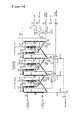
- FIG. 11 illustrates a carbon dioxide capture system using heat transfer media according to one embodiment of the present invention.
- the system of FIG. 11 is distinguished from the systems of FIGS. 7 to 10 in the constitution associated with the use of the heat transfer media.
- the system of FIG. 11 further includes heat exchangers and fluid circulators C4 and C7 to exchange heat of carbon dioxide adsorption and heat of carbon dioxide desorption through the heat transfer media.
Landscapes
- Chemical & Material Sciences (AREA)
- Engineering & Computer Science (AREA)
- Analytical Chemistry (AREA)
- General Chemical & Material Sciences (AREA)
- Oil, Petroleum & Natural Gas (AREA)
- Chemical Kinetics & Catalysis (AREA)
- Environmental & Geological Engineering (AREA)
- Biomedical Technology (AREA)
- Health & Medical Sciences (AREA)
- Dispersion Chemistry (AREA)
- Sustainable Development (AREA)
- Life Sciences & Earth Sciences (AREA)
- Carbon And Carbon Compounds (AREA)
- Treating Waste Gases (AREA)
- Separation Of Gases By Adsorption (AREA)
- Solid-Sorbent Or Filter-Aiding Compositions (AREA)
Abstract
Description
- The present invention relates to carbon dioxide capture systems, and more specifically to carbon dioxide capture systems that prevent carbon dioxide present in flue gases from industrial facilities, such as power plants and steel mills, from being exhausted into the atmosphere.
- Due to recent global warming, the polar icecaps have been melting, causing a rise in the sea level. Recent changes in climate have caused unusual weather phenomena around the world. Global warming is known to be attributed to increased greenhouse gas emissions. International agreements have been signed to restrict the emission of carbon dioxide. Attempts to suppress the emission of carbon dioxide by the introduction of carbon credits become economic issues in individual countries around the world. Efforts to reduce the emission of carbon dioxide have been directed towards the development of alternative energy sources (such as solar energy and wind energy) capable of replacing fossil fuels, and techniques for the capture and storage of carbon dioxide from fossil fuels while preventing the carbon dioxide from being released into the atmosphere. The latter techniques are called carbon capture and storage (CCS) techniques and are broadly divided into techniques for capturing carbon dioxide from power plants and steel mills and techniques for storing captured carbon dioxide in the soil or ocean.
- The carbon dioxide capture techniques can be divided into post-combustion capture, pre-combustion capture, and oxy-fuel capture according to stages at which carbon dioxide is captured. The carbon dioxide capture techniques can also be divided into membrane separation, liquid phase separation, and solid phase separation techniques according to the principles of carbon dioxide capture. The membrane separation techniques use separation membranes to concentrate carbon dioxide, the liquid phase separation techniques use liquid adsorbents such as amines or aqueous ammonia, and the solid phase separation techniques use solid phase adsorbents such as alkali or alkaline earth metals.
- The solid phase separation techniques are largely directed towards the development of solid phase adsorbents Carbon dioxide capture efficiency is greatly affected by the design of adsorption processes as well as the performance of solid phase adsorbents. Solid phase adsorbents can be broadly classified into organic, inorganic, carbon-based, and organic-inorganic hybrid adsorbents by the kind of their constituent materials. Solid phase adsorbents can also be classified into physical adsorbents and chemical adsorbents depending on their forms adsorbed by carbon dioxide. Representative examples of such solid phase adsorbents include: amine polymer adsorbents as organic adsorbents; zeolite-based adsorbents, alkali adsorbents, and alkaline earth metal adsorbents as inorganic adsorbents; activated carbon adsorbents modified with alkali metals as carbon-based adsorbents; and MOF adsorbents and porous silica adsorbents grafted with organic materials having an amine group as organic-inorganic hybrid adsorbents. Carbon dioxide is physically adsorbed to zeolite-based and carbon-based adsorbents. Carbon dioxide is adsorbed to the other adsorbents through chemical reactions (Energy Environ. Sci. 2011, 4, 42. ChemSusChem 2009, 2, 796).
- Solid phase separation includes the steps of adsorbing carbon dioxide to a target object, and desorbing and separating the adsorbed carbon dioxide from the target object. The adsorption and desorption of carbon dioxide may occur reversibly and may be induced through heat exchange or a change in external pressure. Such carbon dioxide capture processes using dry adsorbents are classified into pressure swing adsorption (PSA) processes and temperature swing adsorption (TSA) processes by the factors they use. The PSA processes use a pressure difference and the TSA processes use a temperature difference to desorb adsorbed carbon dioxide. Generally, pressure swing adsorption processes using fixed bed adsorption columns are advantageous in capturing carbon dioxide on a small scale, and an easy-to-scale-up temperature swing adsorption processes using fluidized bed adsorption and desorption columns are advantageous in capturing a large amount of carbon dioxide from power plants or large combustion furnaces.
- The present invention is intended to capture a large amount of carbon dioxide in a continuous manner using solid adsorbents and is based on a temperature swing adsorption process using fluidized bed adsorption columns and fluidized bed desorption columns. The adsorption columns and desorption columns can be divided into bubbling fluidized bed columns and diluted fluidized bed columns according to the concentration of adsorbents in operating regions. Adsorbents are present at high concentrations in the bubbling fluidized bed columns and at low concentrations in the diluted fluidized bed columns. The application of such bubbling fluidized beds and diluted fluidized beds to adsorption columns and desorption columns provides four possible combinations: i) diluted fluidized bed columns-diluted fluidized bed columns, ii) diluted fluidized bed columns-bubbling fluidized bed columns, iii) bubbling fluidized bed columns-diluted fluidized bed columns, and iv) bubbling fluidized bed columns-bubbling fluidized bed columns ("Fluidization Engineering", D. Kunii and O. Levenspiel, Robert E. Krieger, 1977).
- Korean Patent Publication Nos.
2005-0003767 2010-0099929 2011-0054948 - A first object of the present invention is to provide a multi-stage carbon dioxide capture system constructed to use carbon dioxide adsorbents having different adsorption and desorption temperatures so that heat of carbon dioxide adsorption can be used for the desorption of carbon dioxide.
- A second object of the present invention is to provide a carbon dioxide capture system constructed to use heat generated from carbon dioxide adsorption for the desorption of the adsorbed carbon dioxide so that the amount of energy consumed to capture carbon dioxide can be reduced.
- A third object of the present invention is to provide a carbon dioxide capture system constructed to use adsorbents having low carbon dioxide adsorption and desorption rates, achieving efficient heat exchange.
- A fourth object of the present invention is to provide a carbon dioxide capture system constructed to use adsorbents having a low carbon dioxide adsorption rate and a high carbon dioxide desorption rate, achieving efficient heat exchange.
- A fifth object of the present invention is to provide a carbon dioxide capture system constructed to use adsorbents having a high carbon dioxide adsorption rate and a low carbon dioxide desorption rate, achieving efficient heat exchange.
- A sixth object of the present invention is to provide a carbon dioxide capture system constructed to use adsorbents having high carbon dioxide adsorption and desorption rates, achieving efficient heat exchange.
- A seventh object of the present invention is to provide a carbon dioxide capture method using carbon dioxide adsorbents having different carbon dioxide adsorption and desorption temperatures to achieve improved process efficiency.
- In order to achieve the first object of the present invention, there is provided a carbon dioxide capture system for selective separation of carbon dioxide from flue gases, including: a first carbon dioxide adsorption/desorption section including a first carbon dioxide adsorption section, a first carbon dioxide desorption section connected to the first carbon dioxide adsorption section, and a first carbon dioxide adsorbent circulating through the first carbon dioxide adsorption section and the first carbon dioxide desorption section; and a second carbon dioxide adsorption/desorption section including a second carbon dioxide adsorption section, a second carbon dioxide desorption section connected to the second carbon dioxide adsorption section, and a second carbon dioxide adsorbent circulating through the second carbon dioxide adsorption section and the second carbon dioxide desorption section, wherein the first carbon dioxide adsorption section is connected to the second carbon dioxide desorption section such that adsorption heat generated from the first carbon dioxide adsorption section is transferred to the second carbon dioxide desorption section, and the first carbon dioxide adsorbent has different adsorption and desorption temperatures from the second carbon dioxide adsorbent.
- According to one embodiment of the present invention, the first carbon dioxide adsorption section may be connected to the second carbon dioxide desorption section in such a manner that the first carbon dioxide adsorption section penetrates the second carbon dioxide desorption section or the second carbon dioxide desorption section penetrates the first carbon dioxide adsorption section.
- According to a further embodiment of the present invention, the first carbon dioxide adsorption section may be connected to the second carbon dioxide desorption section through a heat transfer medium.
- According to another embodiment of the present invention, the first carbon dioxide desorption section is preferably designed such that the first carbon dioxide desorption section is filled with 0.1 to 10% by volume of the first carbon dioxide adsorbent.
- According to another embodiment of the present invention, the first carbon dioxide desorption section is preferably designed such that the first carbon dioxide desorption section is filled with 10 to 80% by volume of the first carbon dioxide adsorbent.
- According to another embodiment of the present invention, the second carbon dioxide adsorption section is preferably designed such that the second carbon dioxide adsorption section is filled with 0.1 to 10% by volume of the second carbon dioxide adsorbent.
- According to another embodiment of the present invention, the second carbon dioxide adsorption section is preferably designed such that the second carbon dioxide adsorption section is filled with 10 to 80% by volume of the second carbon dioxide adsorbent.
- In order to achieve the second object of the present invention, there is provided a carbon dioxide capture system for selective separation of carbon dioxide from flue gases, including a plurality of carbon dioxide adsorption/desorption sections in which carbon dioxide adsorbents are filled and carbon dioxide is continuously adsorbed and desorbed while the carbon dioxide adsorbents circulate through carbon dioxide adsorption and desorption regions, wherein adsorption heat generated from the carbon dioxide adsorption region of at least one of the carbon dioxide adsorption/desorption sections is transferred to the carbon dioxide desorption region of the adjacent adsorption/desorption section, and at least one of the adsorbents filled in the carbon dioxide adsorption/desorption sections has different carbon dioxide adsorption and desorption temperatures from the other adsorbent(s).
- According to one embodiment of the present invention, adsorption heat generated from the carbon dioxide adsorption region of at least one of the carbon dioxide adsorption/desorption sections may be transferred to the carbon dioxide desorption region of the adjacent adsorption/desorption section in such a manner that the carbon dioxide adsorption region comes into direct contact with the carbon dioxide desorption region.
- According to a further embodiment of the present invention, adsorption heat generated from the carbon dioxide adsorption region of at least one of the carbon dioxide adsorption/desorption sections may be transferred to the carbon dioxide desorption region of the adjacent adsorption/desorption section through a heat transfer medium.
- According to another embodiment of the present invention, a heat exchanger may be provided between the carbon dioxide adsorption region and the carbon dioxide desorption region.
- According to another embodiment of the present invention, the plurality of carbon dioxide adsorption/desorption sections are divided into a high temperature carbon dioxide adsorption/desorption section, an intermediate temperature carbon dioxide adsorption/desorption section, and a low temperature carbon dioxide adsorption/desorption section; adsorption heat generated from a carbon dioxide adsorption region of the high temperature carbon dioxide adsorption/desorption section may be transferred to a carbon dioxide desorption region of the intermediate temperature carbon dioxide adsorption/desorption section; and adsorption heat generated from a carbon dioxide adsorption region of the intermediate temperature carbon dioxide adsorption/desorption section may be transferred to a carbon dioxide desorption region of the low temperature carbon dioxide adsorption/desorption section.
- In order to achieve the third object of the present invention, there is provided a carbon dioxide capture system including a plurality of carbon dioxide adsorption/desorption sections, each of which includes: a bubbling fluidized bed adsorption column in which a carbon dioxide adsorbent is moved from the top to the bottom; a bubbling fluidized bed desorption column in which a carbon dioxide adsorbent is moved from the top to the bottom; a first connection line connecting the bottom of the bubbling fluidized bed adsorption column to the top of the bubbling fluidized bed desorption column; a second connection line connecting the bottom of the bubbling fluidized bed desorption column to the top of the bubbling fluidized bed adsorption column; and a cyclone disposed between the second connection line and the bubbling fluidized bed adsorption column, wherein at least one of the plurality of carbon dioxide adsorption/desorption sections is constructed such that heat is exchangeable.
- In order to achieve the fourth object of the present invention, there is provided a carbon dioxide capture system including a plurality of carbon dioxide adsorption/desorption sections, each of which includes: a bubbling fluidized bed adsorption column in which a carbon dioxide adsorbent is moved from the top to the bottom; a diluted fluidized bed desorption column in which a carbon dioxide adsorbent is moved from the bottom to the top; and a cyclone disposed between the bubbling fluidized bed adsorption column and the diluted fluidized bed desorption column, wherein at least one of the plurality of carbon dioxide adsorption/desorption sections is constructed such that heat is exchangeable.
- In order to achieve the fifth object of the present invention, there is provided a carbon dioxide capture system including a plurality of carbon dioxide adsorption/desorption sections, each of which includes: a diluted fluidized bed adsorption column in which a carbon dioxide adsorbent is moved from the bottom to the top; a bubbling fluidized bed desorption column in which a carbon dioxide adsorbent is moved from the top to the bottom; and a cyclone disposed between the diluted fluidized bed adsorption column and the bubbling fluidized bed desorption column, wherein at least one of the plurality of carbon dioxide adsorption/desorption sections is constructed such that heat is exchangeable.
- In order to achieve the sixth object of the present invention, there is provided a carbon dioxide capture system including a plurality of carbon dioxide adsorption/desorption sections, each of which includes: a diluted fluidized bed adsorption column in which a carbon dioxide adsorbent is moved from the bottom to the top; a diluted fluidized bed desorption column in which a carbon dioxide adsorbent is moved from the bottom to the top; two storage columns connecting the diluted fluidized bed adsorption column to the diluted fluidized bed desorption column; a cyclone disposed between the diluted fluidized bed adsorption column and one of the storage columns; and a cyclone disposed between the diluted fluidized bed desorption column and the other storage column, wherein at least one of the plurality of carbon dioxide adsorption/desorption sections is constructed such that heat is exchangeable.
- In order to achieve the seventh object of the present invention, there is provided a carbon dioxide capture method for selective separation of carbon dioxide from flue gases wherein carbon dioxide is adsorbed and desorbed in a plurality of carbon dioxide adsorption/desorption sections, and at least one of the plurality of carbon dioxide adsorption/desorption sections uses a carbon dioxide adsorbent having different carbon dioxide adsorption and desorption temperatures from a carbon dioxide adsorbent used in the adjacent carbon dioxide adsorption/desorption section.
- According to one embodiment of the present invention, the plurality of carbon dioxide adsorption/desorption sections may be connected to each other such that heat is exchangeable.
- According to a further embodiment of the present invention, the adsorption and desorption temperatures of carbon dioxide in at least one of the plurality of carbon dioxide adsorption/desorption sections are different from those of carbon dioxide in the adjacent carbon dioxide adsorption/desorption section.
- The carbon dioxide capture systems according to the embodiments of the present invention have the following advantageous effects.
- 1. The carbon dioxide capture system according to one embodiment of the present invention includes a plurality of carbon dioxide adsorption/desorption sections and is constructed such that one of the adsorption/desorption sections generates adsorption heat and the adjacent adsorption/desorption section receives and uses the adsorption heat for the desorption of carbon dioxide. This construction can save energy necessary for the adsorption and desorption of carbon dioxide.
- 2. The carbon dioxide capture system according to one embodiment of the present invention is constructed to use carbon dioxide adsorbents having different carbon dioxide adsorption and desorption temperatures. Due to this construction, heat of carbon dioxide adsorption can be used for the desorption of carbon dioxide, achieving efficient energy transfer.
- 3. The carbon dioxide capture system according to one embodiment of the present invention is designed to selectively use diluted fluidized bed or bubbling fluidized bed carbon dioxide adsorption sections and diluted fluidized bed or bubbling fluidized bed carbon dioxide desorption sections in a plurality of carbon dioxide adsorption/desorption sections connected to each other. Due to this design, the carbon dioxide capture system can be efficiently operated depending on the characteristics of adsorbents regarding carbon dioxide adsorption and desorption rates.
- 4. The carbon dioxide capture system according to one embodiment of the present invention is constructed such that heat of carbon dioxide adsorption is directly transferred. This construction can prevent heat loss during transfer of the adsorption heat.
- 5. The carbon dioxide capture system according to one embodiment of the present invention is constructed such that heat of carbon dioxide adsorption is transferred using a heat transfer medium. This simplifies the construction of the system and is advantageous in scaling up the system.
-
-
FIG. 1 is a diagram for explaining the concept of using heat of carbon dioxide adsorption as heat necessary for the desorption of carbon dioxide in a carbon dioxide adsorption-desorption cycle consisting of a low temperature region, an intermediate temperature region, and high temperature region in accordance with one embodiment of the present invention. -
FIG. 2 illustrates main parts of a carbon dioxide capture system including bubbling fluidized bed adsorption columns and bubbling fluidized bed desorption columns according to one embodiment of the present invention. -
FIG. 3 illustrates main parts of a carbon dioxide capture system including bubbling fluidized bed adsorption columns and diluted fluidized bed desorption columns according to one embodiment of the present invention. -
FIG. 4 illustrates main parts of a carbon dioxide capture system including diluted fluidized bed adsorption columns and bubbling fluidized bed desorption columns according to one embodiment of the present invention. -
FIG. 5 illustrates main parts of a carbon dioxide capture system including diluted fluidized bed adsorption columns and diluted fluidized bed desorption columns according to one embodiment of the present invention. -
FIG. 6 is a diagram for explaining the concept of transferring heat of carbon dioxide adsorption to a region necessary for the desorption of carbon dioxide through a heat transfer medium in accordance with one embodiment of the present invention. -
FIG. 7 illustrates a carbon dioxide capture system including bubbling fluidized bed adsorption columns and bubbling fluidized bed desorption columns according to one embodiment of the present invention. -
FIG. 8 illustrates a carbon dioxide capture system including bubbling fluidized bed adsorption columns and diluted fluidized bed desorption columns according to one embodiment of the present invention. -
FIG. 9 illustrates a carbon dioxide capture system including diluted fluidized bed adsorption columns and bubbling fluidized bed desorption columns according to one embodiment of the present invention. -
FIG. 10 illustrates a carbon dioxide capture system including diluted fluidized bed adsorption columns and diluted fluidized bed desorption columns according to one embodiment of the present invention. -
FIG. 11 illustrates a carbon dioxide capture system using heat transfer media according to one embodiment of the present invention. - The present invention will now be described in detail.
- One embodiment of the present invention provides a carbon dioxide capture system including: a first carbon dioxide adsorption/desorption section including a first carbon dioxide adsorption section, a first carbon dioxide desorption section connected to the first carbon dioxide adsorption section, and a first carbon dioxide adsorbent circulating through the first carbon dioxide adsorption section and the first carbon dioxide desorption section; and a second carbon dioxide adsorption/desorption section including a second carbon dioxide adsorption section, a second carbon dioxide desorption section connected to the second carbon dioxide adsorption section, and a second carbon dioxide adsorbent circulating through the second carbon dioxide adsorption section and the second carbon dioxide desorption section, wherein the first carbon dioxide adsorption section is connected to the second carbon dioxide desorption section such that adsorption heat generated from the first carbon dioxide adsorption section is transferred to the second carbon dioxide desorption section, and the first carbon dioxide adsorbent has different adsorption and desorption temperatures from the second carbon dioxide adsorbent.
-
FIG. 1 is a diagram for explaining the concept of using heat of carbon dioxide adsorption as heat necessary for the desorption of carbon dioxide in a carbon dioxide adsorption-desorption cycle consisting of a low temperature region, an intermediate temperature region, and high temperature region in accordance with one embodiment of the present invention. Referring toFIG. 1 , carbon dioxide adsorption/desorption sections in which carbon dioxide is adsorbed and desorbed at different temperatures are multi-stage connected. This connection enables the transfer of energy between the carbon dioxide adsorption/desorption sections where carbon dioxide is adsorbed and desorbed. That is, adsorbents having different adsorption and desorption temperatures are filled in the high temperature, intermediate temperature, and low temperature carbon dioxide adsorption/desorption sections, adsorption heat is generated in the course of desorbing adsorbed carbon dioxide and is transferred to the adjacent region to induce the desorption of carbon dioxide or reduce the amount of heat necessary for desorption. Specifically, adsorption heat is emitted when the adsorbent adsorbs carbon dioxide in the high temperature region and is used as energy necessary for the adsorbent in the intermediate temperature region to desorb the carbon dioxide, and adsorption heat is emitted when the adsorbent adsorbs carbon dioxide in the intermediate temperature region and is used as energy necessary for the adsorbent in the low temperature region to desorb the carbon dioxide. The use of energy generated during adsorption of carbon dioxide as energy necessary for the desorption of carbon dioxide can reduce the cost of energy consumed to desorb the carbon dioxide. - According to embodiments of the present invention, carbon dioxide capture systems may be designed to have various constructions. First, the carbon dioxide capture systems may be constructed to include bubbling fluidized bed or diluted fluidized bed carbon dioxide adsorption sections and bubbling fluidized bed or diluted fluidized bed desorption sections. That is, the following four possible combinations are possible: i) bubbling fluidized bed adsorption sections-bubbling fluidized bed adsorption sections, ii) bubbling fluidized bed adsorption sections-diluted fluidized bed desorption sections, iii) diluted fluidized bed adsorption sections-bubbling fluidized bed desorption sections, and iv) diluted fluidized bed adsorption sections-diluted fluidized bed desorption sections. Each of the bubbling fluidized bed adsorption sections or desorption sections is designed such that it is preferably filled with an adsorbent at a concentration of 10 to 80% by volume, more preferably 30 to 60% by volume. Each of the diluted fluidized bed adsorption sections or desorption sections is designed such that it is preferably filled with an adsorbent at a concentration of 0.1 to 10% by volume, more preferably 0.5 to 5% by volume. The carbon dioxide capture systems are required to have constructions specially designed to use heat of carbon dioxide adsorption for the desorption of carbon dioxide.
- Methods for transferring heat of carbon dioxide adsorption to the adjacent carbon dioxide desorption section may also be modified. One of the modified methods is to exchange heat in a state in which the carbon dioxide adsorption section is in direct contact with the carbon dioxide desorption section. Another modified method is to exchange heat using a heat transfer medium.
- As described earlier, the embodiments of the present invention are broadly classified into 8 modes by the constructions and heat transfer modes of the carbon dioxide adsorption sections and desorption sections, which are summarized in Table 1.
[TABLE 1] Heat exchange mode (Desorption section)-(Adsorption section) combinations Direct mode (without heat transfer medium) (Bubbling fluidized bed)- (Bubbling fluidized bed) (Bubbling fluidized bed)- (Diluted fluidized bed) (Diluted fluidized bed)-(Bubbling fluidized bed) (Diluted fluidized bed)-(Diluted fluidized bed) Indirect mode (using heat transfer medium) (Bubbling fluidized bed)-(Bubbling fluidized bed) (Bubbling fluidized bed)-(Diluted fluidized bed) (Diluted fluidized bed)-(Bubbling fluidized bed) (Diluted fluidized bed)-(Diluted fluidized bed) - Hereinafter, the main constructions and operations of the carbon dioxide capture systems will be described with reference to
FIGS. 2 to 6 . -
FIG. 2 illustrates main parts of a carbon dioxide capture system including bubbling fluidized bed adsorption columns and bubbling fluidized bed desorption columns according to one embodiment of the present invention. The carbon dioxide capture system includes carbon dioxide adsorption/desorption sections, which may be connected in three stages, i.e. low, intermediate, and high temperature stages. An adsorbent in the intermediate temperature region generates heat by adsorption of carbon dioxide. This heat is transferred to the low temperature region by direct heat exchange through the wall of the reactor and is used as energy necessary for the desorption of carbon dioxide in the low temperature region. An adsorbent in the high temperature region generates heat by adsorption of carbon dioxide. This heat is transferred to the intermediate temperature region by direct heat exchange through the wall of the reactor and is used as energy necessary for the desorption of carbon dioxide in the intermediate temperature region. That is, adsorption heat generated during adsorption of carbon dioxide in the higher temperature region is sequentially transferred to the lower temperature region where the adsorption heat is used as energy necessary for the desorption of the adsorbed carbon dioxide. Referring toFIG. 2 , each of the carbon dioxide adsorption/desorption section in the low temperature cycle region and the carbon dioxide adsorption/desorption section in the high temperature cycle region of the bubbling fluidized bed-bubbling fluidized bed carbondioxide capture system 100 includes a bubbling fluidized bed carbondioxide adsorption section 101, a bubbling fluidized bed carbondioxide desorption section 102,cyclones heat exchanger 105, afirst transfer line 106, and asecond transfer line 107. The carbon dioxide adsorption/desorption section in the low temperature cycle region is filled with a carbon dioxide adsorbent having relatively low carbon dioxide adsorption and desorption temperatures, and the carbon dioxide adsorption/desorption section in the high temperature cycle region is filled with a carbon dioxide adsorbent having relatively high carbon dioxide adsorption and desorption temperatures. A flue gas containing carbon dioxide is supplied to the bottom of each bubbling fluidized bed carbondioxide adsorption section 101, and the flue gas free from carbon dioxide is released through thecyclone 103 disposed on the top of the bubbling fluidized bed carbondioxide adsorption section 101. Carbon dioxide is adsorbed to the carbon dioxide adsorbent in the bubbling fluidized bed carbondioxide adsorption section 101. After adsorption, the carbon dioxide adsorbent is moved in the direction from the top to the bottom in the bubbling fluidized bed carbondioxide adsorption section 101 and is supplied to the top of the bubbling fluidized bed carbondioxide desorption section 102 through thefirst transfer line 106. Carbon dioxide is desorbed in the bubbling fluidized bed carbondioxide desorption section 102 and is released through thecyclone 104. After desorption, the adsorbent is transferred from the bottom of the bubbling fluidized bed carbondioxide desorption section 102 to the top of the bubbling fluidized bed carbondioxide adsorption section 101 through thesecond transfer line 107. As this cycle is repeated, carbon dioxide can be captured from the flue gases and released to the outside. The carbon dioxide adsorption section and the carbon dioxide desorption section are connected adjacent to each other and are arranged such that heat is exchangeable therebetween. The figure illustrates that the carbon dioxide adsorption section is arranged so as to penetrate the carbon dioxide desorption section. However, any arrangement is also possible so long as heat can be directly exchanged between the adsorption section and the desorption section. For example, the adsorption section may be connected to the desorption section through a wall. - Cooling means may be placed in the bubbling fluidized bed carbon
dioxide adsorption section 101 and heating means may be placed in the bubbling fluidized bed carbondioxide desorption section 102. The carbon dioxide adsorbent entering the bubbling fluidized bed carbondioxide adsorption section 101 may be precooled and the carbon dioxide adsorbent entering the bubbling fluidized bed carbondioxide desorption section 102 may be preheated. For the precooling and preheating, theheat exchanger 105 may be used. Although not illustrated in the figure, at least one heat exchanger may be further installed at a necessary location. Although not illustrated in the figure, at least one compressor or blower may be provided to move the carbon dioxide adsorbent, if needed. - The carbon dioxide capture system including the bubbling fluidized bed adsorption sections and the bubbling fluidized bed desorption sections is constructed to sufficiently maintain the retention of the adsorbents in the adsorption sections and the desorption sections for a time necessary to adsorb and desorb carbon dioxide. The transfer lines are used for sufficient retention of the adsorbents. This construction is advantageous when the adsorbents for carbon dioxide capture have low adsorption and desorption rates.
-
FIG. 3 illustrates main parts of a carbon dioxide capture system including bubbling fluidized bed adsorption columns and diluted fluidized bed desorption columns according to one embodiment of the present invention. The carbon dioxide capture system includes carbon adsorption/desorption sections, which may be connected in three stages, i.e. low, intermediate, and high temperature stages. Due to this connection, heat of carbon dioxide adsorption may be transferred from the high temperature region to the intermediate temperature region and from the intermediate temperature region to the low temperature region. Referring toFIG. 3 , each of the carbon dioxide adsorption/desorption section in the low temperature cycle region and the carbon dioxide adsorption/desorption section in the high temperature cycle region of the bubbling fluidized bed-diluted fluidized bed carbondioxide capture system 200 includes a bubbling fluidized bed carbondioxide adsorption section 201, a diluted fluidized bed carbondioxide desorption section 202, acyclone 203, and aheat exchanger 205. A flue gas containing carbon dioxide is supplied to the bottom of each bubbling fluidized bed carbondioxide adsorption section 201, and the flue gas free from carbon dioxide is released from the top of the bubbling fluidized bed carbondioxide adsorption section 201. Carbon dioxide is adsorbed to a carbon dioxide adsorbent in the bubbling fluidized bed carbondioxide adsorption section 201. After adsorption, the carbon dioxide adsorbent is moved in the direction from the top to the bottom in the bubbling fluidized bed carbondioxide adsorption section 201 and is supplied to the bottom of the diluted fluidized bed carbondioxide desorption section 202. While the carbon dioxide adsorbent entering the diluted fluidized bed carbondioxide desorption section 202 is moved from the bottom to the top, carbon dioxide is desorbed from the carbon dioxide adsorbent. The desorbed carbon dioxide is released through thecyclone 203 and the carbon dioxide adsorbent is again supplied to the top of the bubbling fluidized bed carbondioxide adsorption section 201. The carbon dioxide adsorption section and the carbon dioxide desorption section are connected adjacent to each other and are arranged such that heat is exchangeable therebetween. The fluidized bed carbondioxide desorption section 202 is arranged so as to penetrate the bubbling fluidized bed carbondioxide adsorption section 201 and heat is exchanged through the wall. In this embodiment as well, any arrangement is also possible so long as heat can be directly exchanged between the adsorption section and the desorption section. For example, the adsorption section may be connected to the desorption section through a wall. Cooling means may be placed in the bubbling fluidized bed carbondioxide adsorption section 201 and heating means may be placed in the diluted fluidized bed carbondioxide desorption section 202. Preheating or precooling means may be further provided to preheat or precool the carbon dioxide adsorbent. At least one compressor or blower may be further provided to move the carbon dioxide adsorbent. - The carbon dioxide capture system including the bubbling fluidized bed adsorption sections and the diluted fluidized bed desorption sections is constructed to sufficiently maintain the retention of the adsorbents in the adsorption sections for a time necessary to adsorb carbon dioxide. The retention time of the adsorbents in the carbon dioxide desorption sections may be determined depending on the operating conditions of the system. This construction is advantageous when the adsorbents have a low carbon dioxide adsorption rate and a high carbon dioxide desorption rate.
-
FIG. 4 illustrates main parts of a carbon dioxide capture system including diluted fluidized bed adsorption columns and bubbling fluidized bed desorption columns according to one embodiment of the present invention. The carbon dioxide capture system includes carbon dioxide adsorption/desorption sections, which may be connected in three stages, i.e. low, intermediate, and high temperature stages. Due to this connection, heat of carbon dioxide adsorption may be transferred from the high temperature region to the intermediate temperature region and from the intermediate temperature region to the low temperature region. Referring toFIG. 4 , each of the carbon dioxide adsorption/desorption section in the low temperature cycle region and the carbon dioxide adsorption/desorption section in the high temperature cycle region of the diluted fluidized bed-bubbling fluidized bed carbondioxide capture system 300 includes a diluted fluidized bed carbondioxide adsorption section 301, a bubbling fluidized bed carbondioxide desorption section 302, acyclone 303, and aheat exchanger 305. A flue gas containing carbon dioxide is supplied to the bottom of each diluted fluidized bed carbondioxide adsorption section 301, and the flue gas free from carbon dioxide is released through thecyclone 303 disposed on the diluted fluidized bed carbondioxide adsorption section 301. Carbon dioxide is adsorbed to a carbon dioxide adsorbent in the diluted fluidized bed carbondioxide adsorption section 301. After adsorption, the carbon dioxide adsorbent is moved in the direction from the bottom to the top in the diluted fluidized bed carbondioxide adsorption section 301 and is supplied to the top of the bubbling fluidized bed carbondioxide desorption section 302. While the carbon dioxide adsorbent entering the bubbling fluidized bed carbondioxide desorption section 302 is moved in the direction from the top to the bottom, carbon dioxide is desorbed from the carbon dioxide adsorbent. The carbon dioxide adsorption section and the carbon dioxide desorption section are connected adjacent to each other and are arranged such that heat is exchangeable therebetween. The diluted fluidized bed carbondioxide adsorption section 301 is arranged so as to penetrate the bubbling fluidized bed carbondioxide desorption section 302 and heat is exchanged through the wall. In this embodiment as well, any arrangement is also possible so long as heat can be directly exchanged between the adsorption section and the desorption section. For example, the adsorption section may be connected to the desorption section through a wall. Cooling means may be placed in the diluted fluidized bed carbondioxide adsorption section 301 and heating means may be placed in the bubbling fluidized bed carbondioxide desorption section 302. Preheating or precooling means may be further provided to preheat or precool the carbon dioxide adsorbent. At least one compressor or blower may be further provided to move the carbon dioxide adsorbent. - The retention time of the adsorbents in the carbon dioxide desorption sections of the carbon dioxide capture system may be determined depending on the operating conditions of the system. This construction is advantageous when the adsorbents have a high carbon dioxide adsorption rate and a low carbon dioxide desorption rate.
-
FIG. 5 illustrates main parts of a carbon dioxide capture system including diluted fluidized bed adsorption columns and diluted fluidized bed desorption columns according to one embodiment of the present invention. The carbon dioxide capture system includes carbon dioxide adsorption/desorption sections, which may be connected in three stages, i.e. low, intermediate, and high temperature stages. Due to this connection, heat of carbon dioxide adsorption may be transferred from the high temperature region to the intermediate temperature region and from the intermediate temperature region to the low temperature region. Referring toFIG. 5 , each of the carbon dioxide adsorption/desorption section in the low temperature cycle region and the carbon dioxide adsorption/desorption section in the high temperature cycle region of the diluted fluidized bed-diluted fluidized bed carbondioxide capture system 400 includes a diluted fluidized bed carbondioxide adsorption section 401, a diluted fluidized bed carbondioxide desorption section 402,cyclones heat exchanger 405, andstorage columns dioxide adsorption section 401, and the flue gas free from carbon dioxide is released through thecyclone 403 disposed on the diluted fluidized bed carbondioxide adsorption section 401. Carbon dioxide is adsorbed to a carbon dioxide adsorbent in the diluted fluidized bed carbondioxide adsorption section 401. After adsorption, the carbon dioxide adsorbent is moved in the direction from the bottom to the top in the diluted fluidized bed carbondioxide adsorption section 401 and is subsequently supplied to the top of thestorage column 406 and the bottom of the diluted fluidized bed carbondioxide desorption section 402. While the carbon dioxide adsorbent entering the diluted fluidized bed carbondioxide desorption section 402 is moved in the direction from the bottom to the top, carbon dioxide is desorbed from the carbon dioxide adsorbent and is released through thecyclone 404. Thereafter, the carbon dioxide adsorbent is supplied to the bottom of the diluted fluidized bed carbondioxide adsorption section 401 through thestorage column 407. Since the carbon dioxide adsorbents are moved in the direction from the bottom to the top in both the adsorption section and the desorption section, spaces are required to accommodate the adsorbents separated from the cyclones. Thestorage columns dioxide adsorption section 401 is arranged so as to penetrate the diluted fluidized bed carbondioxide desorption section 402 and heat is exchanged through the wall. In this embodiment as well, any arrangement is also possible so long as heat can be directly exchanged between the adsorption section and the desorption section. For example, the adsorption section may be connected to the desorption section through a wall. Cooling means may be placed in the diluted fluidized bed carbondioxide adsorption section 401 and heating means may be placed in the diluted fluidized bed carbondioxide desorption section 402. Preheating or precooling means may be further provided to preheat or precool the carbon dioxide adsorbent. At least one compressor or blower may be further provided to move the carbon dioxide adsorbent. - The retention time of the adsorbents in the carbon dioxide adsorption sections and desorption sections of the carbon dioxide capture system may be determined depending on the operating conditions of the system. This construction is advantageous when the adsorbents have high adsorption and desorption rates.
-
FIG. 6 is a diagram for explaining the concept of transferring heat of carbon dioxide adsorption to a region necessary for the desorption of carbon dioxide through a heat transfer medium in accordance with one embodiment of the present invention. Referring toFIG. 6 , the carbondioxide capture system 500 includes diluted fluidized bed carbondioxide adsorption sections 501, bubbling fluidized bed carbondioxide desorption sections 502, and aheat transfer medium 503. Theheat transfer medium 503 connects the carbondioxide adsorption section 501 to the bubbling fluidized bed carbondioxide desorption section 502 and functions as a medium to transfer heat of carbon dioxide adsorption to the desorption section. The transfer of heat through the heat transfer medium enables free design of the parts of the system, thus being advantageous in simplifying or scaling-up the construction of the system. The heat transfer medium is composed of a material having a high thermal conductivity. The system may include heat insulating means surrounding the outer surface thereof. The heat insulating means may be, for example, a heat insulating water jacket or silicone oil jacket. The carbon dioxide capture system ofFIG. 6 including the diluted fluidized bed carbon dioxide adsorption sections and the bubbling fluidized bed carbon dioxide desorption sections is exemplified for ease of explanation. The heat transfer medium may also be applied to other carbon dioxide capture systems. - A detailed description will be given concerning the constructions and operations of the carbon dioxide capture systems with reference to
FIGS. 7 to 11 . These figures explain the embodiments of the present invention and some of the parts may be omitted or modified depending on the characteristics of the carbon dioxide adsorbents and the operating conditions of the systems. -
FIGS. 7 to 10 illustrate the carbon dioxide capture systems according to the embodiments of the present invention. The carbon dioxide adsorption/desorption sections of the carbon dioxide capture systems have a combination of bubbling fluidized bed adsorption columns and bubbling fluidized bed desorption columns, a combination of bubbling fluidized bed adsorption columns and diluted fluidized bed desorption columns, a combination of diluted fluidized bed adsorption columns and bubbling fluidized bed desorption columns, or a combination of diluted fluidized bed adsorption columns and diluted fluidized bed desorption columns in a direct heat exchange mode. The carbon dioxide capture systems ofFIGS. 7 to 10 are different from each other in the construction and connection of the carbon dioxide adsorption columns and the carbon dioxide desorption columns. The differences have been described inFIGS. 2 to 5 and a repeated explanation thereof is omitted. Hereinafter, an explanation will be given concerning the constitutions necessary for understanding the feeding of flue gases, the release of carbon dioxide, and the movement of carbon dioxide adsorbents. Referring toFIGS. 7 to 10 , each of the carbon dioxide capture systems includes carbon dioxide adsorption/desorption sections, cyclones, adsorbent transfer lines, heat exchangers, fluid circulators, heaters, and flow regulating valves. A flue gas containing carbon dioxide is supplied through a compressor or ventilator as the fluid circulator C1 and is supplied to and distributed in the adsorption columns in the respective temperature regions by means of the flow regulating valves V1, V2 and V3. Flue gases in the respective temperature regions are heated to optimum temperatures for carbon dioxide adsorption and are introduced into the adsorption columns through the heat exchangers HX3 and HX6. Since the adsorbents in the low, intermediate, and high temperature regions have higher desorption temperatures than the carbon dioxide adsorption temperatures, the temperature differences may cause the problem of low heat efficiency during repeated adsorption-desorption cycles. This problem is solved by heating the adsorbents after carbon dioxide adsorption before the adsorbents are fed into the desorption columns and by cooling the adsorbents after carbon dioxide desorption before the adsorbents are fed into the adsorption columns. For the preheating and precooling, the heat exchangers HX1, HX2, HX4, HX5, HX7, and HX8 are provided between the adsorption columns and the desorption columns such that heat is exchanged in each stage. The fluid circulators C2, C5, and C8 are placed for smooth heat exchange during circulation of heat transfer media through the heat exchangers. That is, the adsorbents after adsorption are heated before being fed into the desorption columns and the adsorbents after desorption are cooled before being fed into the adsorption columns. The preheating and precooling minimize the amount of heat necessary for adsorption and desorption. For transfer of the adsorbents, the adsorbents having passed through stream numbers S4, S17, and S29 are fed into the cyclones CY1, CY3, and CY5 through the transfer lines (S4→CY1, S17→CY3, and S29→CY5). The carbon dioxide adsorption/desorption sections SC3, SC5, and SC6 are installed in the low, intermediate and high temperature regions, respectively, for direct heat exchange through the wall surfaces of the reactors. The cyclones CY1, CY2, CY3, CY4, CY5, and CY6 are disposed to separate the adsorbents from gases released from the carbon dioxide adsorption/desorption sections. The heater FH1 is placed to receive energy necessary for desorption of the adsorbent in the high temperature region from the outside. The heat exchangers HX9 and HX10 are placed to exchange heat between concentrated carbon dioxide escaping from the desorption columns and a flue gas from a heating furnace. This heat exchange minimizes the supply of energy. -
FIG. 11 illustrates a carbon dioxide capture system using heat transfer media according to one embodiment of the present invention. Referring toFIG. 11 , most of the parts of the system are the same as those explained inFIGS. 7 to 10 . The system ofFIG. 11 is distinguished from the systems ofFIGS. 7 to 10 in the constitution associated with the use of the heat transfer media. Specifically, the system ofFIG. 11 further includes heat exchangers and fluid circulators C4 and C7 to exchange heat of carbon dioxide adsorption and heat of carbon dioxide desorption through the heat transfer media. - Although the technical spirit of the present invention has been described with reference to the foregoing embodiments, those skilled in the art will appreciate that various variations and modifications are possible without departing from the essential features of the present invention. Therefore, the embodiments are merely illustrative and are not to be considered as limiting the technical spirit of the present invention. The scope of the invention is defined by the appended claims and all technical spirit within the range of equivalency of the claims should be construed as falling within the scope of the invention.
-
- 100: Bubbling fluidized bed-bubbling fluidized bed carbon dioxide capture system
- 101: Bubbling fluidized bed carbon dioxide adsorption section
- 102: Bubbling fluidized bed carbon dioxide desorption section
- 103, 104: Cyclones 105: Heat exchanger
- 106: First transfer line 107: Second transfer line
- 200: Bubbling fluidized bed-diluted fluidized bed carbon dioxide capture system
- 201: Bubbling fluidized bed carbon dioxide adsorption section
- 202: Diluted fluidized bed carbon dioxide desorption section
- 203: Cyclone 205: Heat exchanger
- 300: Diluted fluidized bed-bubbling fluidized bed carbon dioxide capture system
- 301: Diluted fluidized bed carbon dioxide adsorption section
- 302: Bubbling fluidized bed carbon dioxide desorption section
- 303: Cyclone 305: Heat exchanger
- 400: Diluted fluidized bed-diluted fluidized bed carbon dioxide capture system
- 401: Diluted fluidized bed carbon dioxide adsorption section
- 402: diluted fluidized bed carbon dioxide desorption section
- 403, 404: Cyclones 405: Heat exchanger
- 406, 407: Storage columns
- 500: Carbon dioxide capture system using heat transfer medium
- 501: Diluted fluidized bed carbon dioxide adsorption section
- 502: Bubbling fluidized bed carbon dioxide desorption section
- 503: Heat transfer medium
- C1-C10: Fluid circulators CY1-CY6: Cyclones
- FH1: Heater HX1-HX10: Heat exchangers
- SC1-SC6: Carbon dioxide adsorption/desorption sections
- S1-546: Stream numbers V1-V3: Flow regulating valves
Claims (19)
- A carbon dioxide capture system for selective separation of carbon dioxide from flue gases, comprising:a first carbon dioxide adsorption/desorption section comprising a first carbon dioxide adsorption section, a first carbon dioxide desorption section connected to the first carbon dioxide adsorption section, and a first carbon dioxide adsorbent circulating through the first carbon dioxide adsorption section and the first carbon dioxide desorption section; anda second carbon dioxide adsorption/desorption section comprising a second carbon dioxide adsorption section, a second carbon dioxide desorption section connected to the second carbon dioxide adsorption section, and a second carbon dioxide adsorbent circulating through the second carbon dioxide adsorption section and the second carbon dioxide desorption section,wherein the first carbon dioxide adsorption section is connected to the second carbon dioxide desorption section such that adsorption heat generated from the first carbon dioxide adsorption section is transferred to the second carbon dioxide desorption section, and the first carbon dioxide adsorbent has different adsorption and desorption temperatures from the second carbon dioxide adsorbent.
- The carbon dioxide capture system according to claim 1, wherein the first carbon dioxide adsorption section is connected to the second carbon dioxide desorption section in such a manner that the first carbon dioxide adsorption section penetrates the second carbon dioxide desorption section or the second carbon dioxide desorption section penetrates the first carbon dioxide adsorption section.
- The carbon dioxide capture system according to claim 1, wherein the first carbon dioxide adsorption section is connected to the second carbon dioxide desorption section through a heat transfer medium.
- The carbon dioxide capture system according to claim 1, wherein the first carbon dioxide desorption section is designed such that the first carbon dioxide desorption section is filled with 0.1 to 10% by volume of the first carbon dioxide adsorbent.
- The carbon dioxide capture system according to claim 1, wherein the first carbon dioxide desorption section is designed such that the first carbon dioxide desorption section is filled with 10 to 80% by volume of the first carbon dioxide adsorbent.
- The carbon dioxide capture system according to claim 1, wherein the second carbon dioxide adsorption section is designed such that the second carbon dioxide adsorption section is filled with 0.1 to 10% by volume of the second carbon dioxide adsorbent.
- The carbon dioxide capture system according to claim 1, wherein the second carbon dioxide adsorption section is designed such that the second carbon dioxide adsorption section is filled with 10 to 80% by volume of the second carbon dioxide adsorbent.
- A carbon dioxide capture system for selective separation of carbon dioxide from flue gases, comprising a plurality of carbon dioxide adsorption/desorption sections in which carbon dioxide adsorbents are filled and carbon dioxide is continuously adsorbed and desorbed while the carbon dioxide adsorbents circulate through carbon dioxide adsorption and desorption regions,
wherein adsorption heat generated from the carbon dioxide adsorption region of at least one of the carbon dioxide adsorption/desorption sections is transferred to the carbon dioxide desorption region of the adjacent adsorption/desorption section, and at least one of the adsorbents filled in the carbon dioxide adsorption/desorption sections has different carbon dioxide adsorption and desorption temperatures from the other adsorbent(s). - The carbon dioxide capture system according to claim 8, wherein adsorption heat generated from the carbon dioxide adsorption region of at least one of the carbon dioxide adsorption/desorption sections is transferred to the carbon dioxide desorption region of the adjacent adsorption/desorption section in such a manner that the carbon dioxide adsorption region comes into direct contact with the carbon dioxide desorption region.
- The carbon dioxide capture system according to claim 8, wherein adsorption heat generated from the carbon dioxide adsorption region of at least one of the carbon dioxide adsorption/desorption sections is transferred to the carbon dioxide desorption region of the adjacent adsorption/desorption section through a heat transfer medium.
- The carbon dioxide capture system according to claim 8, wherein a heat exchanger is provided between the carbon dioxide adsorption region and the carbon dioxide desorption region.
- The carbon dioxide capture system according to claim 8, wherein the plurality of carbon dioxide adsorption/desorption sections are divided into a high temperature carbon dioxide adsorption/desorption section, an intermediate temperature carbon dioxide adsorption/desorption section, and a low temperature carbon dioxide adsorption/desorption section; adsorption heat generated from a carbon dioxide adsorption region of the high temperature carbon dioxide adsorption/desorption section is transferred to a carbon dioxide desorption region of the intermediate temperature carbon dioxide adsorption/desorption section; and adsorption heat generated from a carbon dioxide adsorption region of the intermediate temperature carbon dioxide adsorption/desorption section is transferred to a carbon dioxide desorption region of the low temperature carbon dioxide adsorption/desorption section.
- A carbon dioxide capture system comprising a plurality of carbon dioxide adsorption/desorption sections, each of which comprises: a bubbling fluidized bed adsorption column in which a carbon dioxide adsorbent is moved from the top to the bottom; a bubbling fluidized bed desorption column in which a carbon dioxide adsorbent is moved from the top to the bottom; a first connection line connecting the bottom of the bubbling fluidized bed adsorption column to the top of the bubbling fluidized bed desorption column; a second connection line connecting the bottom of the bubbling fluidized bed desorption column to the top of the bubbling fluidized bed adsorption column; and a cyclone disposed between the second connection line and the bubbling fluidized bed adsorption column, wherein at least one of the plurality of carbon dioxide adsorption/desorption sections is constructed such that heat is exchangeable.
- A carbon dioxide capture system comprising a plurality of carbon dioxide adsorption/desorption sections, each of which comprises: a bubbling fluidized bed adsorption column in which a carbon dioxide adsorbent is moved from the top to the bottom; a diluted fluidized bed desorption column in which a carbon dioxide adsorbent is moved from the bottom to the top; and a cyclone disposed between the bubbling fluidized bed adsorption column and the diluted fluidized bed desorption column, wherein at least one of the plurality of carbon dioxide adsorption/desorption sections is constructed such that heat is exchangeable.
- A carbon dioxide capture system comprising a plurality of carbon dioxide adsorption/desorption sections, each of which comprises: a diluted fluidized bed adsorption column in which a carbon dioxide adsorbent is moved from the bottom to the top; a bubbling fluidized bed desorption column in which a carbon dioxide adsorbent is moved from the top to the bottom; and a cyclone disposed between the diluted fluidized bed adsorption column and the bubbling fluidized bed desorption column, wherein at least one of the plurality of carbon dioxide adsorption/desorption sections is constructed such that heat is exchangeable.
- A carbon dioxide capture system comprising a plurality of carbon dioxide adsorption/desorption sections, each of which comprises: a diluted fluidized bed adsorption column in which a carbon dioxide adsorbent is moved from the bottom to the top; a diluted fluidized bed desorption column in which a carbon dioxide adsorbent is moved from the bottom to the top; two storage columns connecting the diluted fluidized bed adsorption column to the diluted fluidized bed desorption column; a cyclone disposed between the diluted fluidized bed adsorption column and one of the storage columns; and a cyclone disposed between the diluted fluidized bed desorption column and the other storage column, wherein at least one of the plurality of carbon dioxide adsorption/desorption sections is constructed such that heat is exchangeable.
- A carbon dioxide capture method for selective separation of carbon dioxide from flue gases wherein carbon dioxide is adsorbed and desorbed in a plurality of carbon dioxide adsorption/desorption sections, and at least one of the plurality of carbon dioxide adsorption/desorption sections uses a carbon dioxide adsorbent having different carbon dioxide adsorption and desorption temperatures from a carbon dioxide adsorbent used in the adjacent carbon dioxide adsorption/desorption section.
- The carbon dioxide capture method according to claim 17, wherein the plurality of carbon dioxide adsorption/desorption sections are connected to each other such that heat is exchangeable.
- The carbon dioxide capture method according to claim 17, wherein the adsorption and desorption temperatures of carbon dioxide in at least one of the plurality of carbon dioxide adsorption/desorption sections are different from those of carbon dioxide in the adjacent carbon dioxide adsorption/desorption section.
Applications Claiming Priority (2)
| Application Number | Priority Date | Filing Date | Title |
|---|---|---|---|
| KR1020120107160A KR101381443B1 (en) | 2012-06-27 | 2012-09-26 | Apparatus for capturing of carbon dioxide |
| PCT/KR2013/000583 WO2014051221A1 (en) | 2012-09-26 | 2013-01-25 | Carbon dioxide capturing apparatus |
Publications (3)
| Publication Number | Publication Date |
|---|---|
| EP2902088A1 true EP2902088A1 (en) | 2015-08-05 |
| EP2902088A4 EP2902088A4 (en) | 2016-06-15 |
| EP2902088B1 EP2902088B1 (en) | 2018-06-06 |
Family
ID=50389674
Family Applications (1)
| Application Number | Title | Priority Date | Filing Date |
|---|---|---|---|
| EP13841840.5A Active EP2902088B1 (en) | 2012-09-26 | 2013-01-25 | Carbon dioxide capturing apparatus |
Country Status (5)
| Country | Link |
|---|---|
| US (1) | US8894753B2 (en) |
| EP (1) | EP2902088B1 (en) |
| KR (1) | KR101381443B1 (en) |
| ES (1) | ES2682920T3 (en) |
| WO (1) | WO2014051221A1 (en) |
Families Citing this family (15)
| Publication number | Priority date | Publication date | Assignee | Title |
|---|---|---|---|---|
| KR101571966B1 (en) * | 2013-03-13 | 2015-11-26 | 한국화학연구원 | Apparatus for capturing of carbon dioxide |
| WO2015056272A2 (en) * | 2013-10-09 | 2015-04-23 | Reliance Industries Limited | A multi-compression system and process for capturing carbon dioxide |
| KR101509389B1 (en) * | 2014-01-28 | 2015-04-08 | 연세대학교 산학협력단 | Stack of plate type reactor for capturing of carbon dioxide |
| US10232307B2 (en) * | 2014-11-10 | 2019-03-19 | Shell Oil Company | Process for capturing CO2 from a gas stream |
| US9387430B2 (en) * | 2014-11-19 | 2016-07-12 | Apache Corporation | Methods and systems of enhanced carbon dioxide recovery |
| CN106345222A (en) * | 2016-09-29 | 2017-01-25 | 天津大学 | Solar thermal assisted temperature swing adsorption carbon trapping system |
| KR102033745B1 (en) | 2019-06-28 | 2019-10-17 | 한국화학연구원 | Apparatus and process for capturing of carbon dioxide |
| US12327854B2 (en) | 2020-05-30 | 2025-06-10 | Solomon Alema Asfha | Apparatuses and methods for carbon dioxide capturing and electrical energy producing system |
| CN112844033A (en) * | 2021-01-07 | 2021-05-28 | 太原理工大学 | CO capture2Bubbling conveying fluidized bed reaction device and process |
| US11612853B1 (en) * | 2022-01-02 | 2023-03-28 | AirMyne, Inc. | Fully automated direct air capture carbon dioxide processing system |
| DE102023202651A1 (en) * | 2023-03-23 | 2024-09-26 | Volkswagen Aktiengesellschaft | Plant and process for separating carbon dioxide from ambient air |
| US12350621B2 (en) * | 2023-07-17 | 2025-07-08 | Schlumberger Technology Corporation | Box chain conveyor adsorption moving bed with heat integration |
| KR102852739B1 (en) * | 2023-11-29 | 2025-09-01 | 한국기계연구원 | Dry type absorbing molding and carbon dioxide absorption apparatus for ships using the dry type absorbing molding |
| CN118454411B (en) * | 2024-07-09 | 2024-11-22 | 深碳科技(深圳)有限公司 | Solid amine carbon capture system for various particle sizes |
| CN119435162A (en) * | 2025-01-09 | 2025-02-14 | 东方电气集团东方汽轮机有限公司 | Coal-fired power exhaust carbon capture and carbon dioxide energy storage integrated system and control method |
Family Cites Families (29)
| Publication number | Priority date | Publication date | Assignee | Title |
|---|---|---|---|---|
| US1577534A (en) * | 1922-06-15 | 1926-03-23 | Silica Gel Corp | Method and apparatus for separating or recovering alpha gas from alpha mixture of gases |
| US3719573A (en) * | 1970-01-26 | 1973-03-06 | Environment One Corp | Periodically reversed gas flow ozone production method and apparatus |
| US3786135A (en) * | 1971-09-07 | 1974-01-15 | Aluminum Co Of America | Recovery of solid selectively constituted high purity aluminum chloride from hot gaseous effluent |
| US3921544A (en) * | 1972-04-26 | 1975-11-25 | Combustion Power | Method and apparatus for particle collection in the exhaust of a fluid bed disposal apparatus |
| US4373935A (en) * | 1981-05-01 | 1983-02-15 | Union Carbide Corporation | Adsorption separation cycle |
| US4405343A (en) * | 1982-09-01 | 1983-09-20 | Othmer Donald F | Methanol dehydration |
| DE3371247D1 (en) * | 1982-11-04 | 1987-06-04 | Matsushita Electric Industrial Co Ltd | Heat exchanger |
| US4950311A (en) * | 1988-03-07 | 1990-08-21 | White Jr Donald H | Heaterless adsorption system for combined purification and fractionation of air |
| US5110323A (en) | 1990-01-04 | 1992-05-05 | Stone & Webster Engineering Corp. | Process for the return of recovered particulate solids by a cyclone separator to a vessel |
| US5156657A (en) | 1990-03-29 | 1992-10-20 | The Boc Group, Inc. | Process for pre-purification of air for separation |
| US5170633A (en) * | 1991-06-24 | 1992-12-15 | Amsted Industries Incorporated | Desiccant based air conditioning system |
| JPH05237329A (en) * | 1991-08-30 | 1993-09-17 | Chiyoda Corp | Method and device for separating gas |
| US5676738A (en) | 1995-08-22 | 1997-10-14 | Cioffi; Lawrence | VOC control/solvent recovery system |
| US6199388B1 (en) * | 1999-03-10 | 2001-03-13 | Semco Incorporated | System and method for controlling temperature and humidity |
| JP2001137646A (en) | 1999-11-15 | 2001-05-22 | Kureha Techno Enji Kk | Device and method for adsorption treating waste gas |
| EP1590080A2 (en) * | 2002-12-18 | 2005-11-02 | University Of Ottawa | Amine modified adsorbent, its preparation and use for dry scrubbing of acid gases |
| KR100527420B1 (en) | 2003-07-04 | 2005-11-09 | 한국에너지기술연구원 | CO2 capturing process |
| US20070283812A1 (en) * | 2006-06-09 | 2007-12-13 | General Electric Company | System and method for removing sulfur from fuel gas streams |
| KR100870756B1 (en) * | 2007-04-23 | 2008-11-26 | 한국에너지기술연구원 | Method and apparatus for solid conveying circulation between two fluidized beds |
| KR100912250B1 (en) * | 2007-11-09 | 2009-08-14 | 한국에너지기술연구원 | Cyclone Expander of CO2 Recovery System Using Dry Absorber |
| US8500851B2 (en) * | 2008-11-10 | 2013-08-06 | Phillips 66 Company | Multiple fixed-fluidized beds for contaminant removal |
| KR101069191B1 (en) | 2009-03-04 | 2011-09-30 | 한국에너지기술연구원 | CO₂ recovery system with transport regeneration reactor |
| KR101146710B1 (en) * | 2009-06-16 | 2012-05-17 | 한국에너지기술연구원 | Apparatus and method for recovering carbon dioxide from flue gas using temperature swing adsorption |
| KR101094325B1 (en) * | 2009-11-18 | 2011-12-19 | 한국에너지기술연구원 | Vortex tube device and carbon dioxide absorption separation system using the same |
| KR101045061B1 (en) | 2009-11-19 | 2011-06-29 | 한국에너지기술연구원 | CO2 recovery system with regeneration reactor in the form of multi-stage fluidized bed heat exchanger |
| JP5641194B2 (en) | 2010-03-31 | 2014-12-17 | 新日鉄住金エンジニアリング株式会社 | Carbon dioxide gas recovery device |
| GB2486476A (en) * | 2010-12-16 | 2012-06-20 | Doosan Power Systems Ltd | Method and apparatus for the regeneration of a capture medium |
| US20120160098A1 (en) * | 2010-12-22 | 2012-06-28 | Hamilton Sundstrand Corporation | Method and system for carbon dioxide removal |
| KR101336778B1 (en) * | 2011-12-12 | 2013-12-05 | 한국에너지기술연구원 | Dry sorbent CO2 capturing device using multi sorbents |
-
2012
- 2012-09-26 KR KR1020120107160A patent/KR101381443B1/en active Active
-
2013
- 2013-01-25 WO PCT/KR2013/000583 patent/WO2014051221A1/en not_active Ceased
- 2013-01-25 ES ES13841840.5T patent/ES2682920T3/en active Active
- 2013-01-25 EP EP13841840.5A patent/EP2902088B1/en active Active
- 2013-01-25 US US14/350,363 patent/US8894753B2/en active Active
Also Published As
| Publication number | Publication date |
|---|---|
| EP2902088B1 (en) | 2018-06-06 |
| KR101381443B1 (en) | 2014-04-04 |
| US20140251136A1 (en) | 2014-09-11 |
| US8894753B2 (en) | 2014-11-25 |
| ES2682920T3 (en) | 2018-09-24 |
| WO2014051221A1 (en) | 2014-04-03 |
| KR20140001721A (en) | 2014-01-07 |
| EP2902088A4 (en) | 2016-06-15 |
Similar Documents
| Publication | Publication Date | Title |
|---|---|---|
| US8894753B2 (en) | Carbon dioxide capture systems | |
| EP2954942B1 (en) | Carbon dioxide collection device | |
| US20250128202A1 (en) | Carbon dioxide capturing apparatus and capturing method | |
| CN111278529B (en) | Gas recovery and concentration device | |
| CN102639209B (en) | Carbon dioxide capture/regeneration structures and technologies | |
| JP5485812B2 (en) | Carbon dioxide recovery device | |
| CN104162341A (en) | Device and method for removing CO2 from smoke by using solid amine adsorbent | |
| McDonough et al. | Intensified carbon capture using adsorption: Heat transfer challenges and potential solutions | |
| JP2020527455A (en) | Use of V-type adsorbents and gas concentrates for CO2 adsorption and capture | |
| US20240399290A1 (en) | Gas Capture System Comprising a Heat Pump Using a Liquid Sorbent With Combined Temperature and Pressure Swings | |
| KR102055976B1 (en) | A single compression system and process for capturing carbon dioxide | |
| CN108472571A (en) | Carbon dioxide separation retracting device, using its combustion system and thermal power generation system and carbon dioxide separation and recovery method | |
| WO2025092856A1 (en) | Fixed-bed flue gas purification system and control method therefor | |
| WO2025092857A1 (en) | Multifunctional flue-gas purification device and control method therefor | |
| US10029205B2 (en) | Two stage adsorbent and process cycle for fluid separations | |
| US9316123B2 (en) | Power generation system and processes thereof, including adsorbing heat exchangers for CO2 capture from fossil fuel consumption | |
| JP2009262086A (en) | Method of recovering carbon dioxide of coal boiler exhaust gas and system for recovering this carbon dioxide | |
| KR100534543B1 (en) | Oxygen enrichment system using temperature swing adsorption with combustion waste heat | |
| JP4264740B2 (en) | Small desiccant air conditioner | |
| CN101757832A (en) | Method for separating at least one component from multi-component mixed fluid and device thereof | |
| CN109173568B (en) | Active carbon level difference adsorption safe concentration method | |
| Van Paasen et al. | Process development for large scale solid sorbent post combustion CO2 capture technology for application to natural gas fired power stations | |
| JP2020199434A (en) | Air conditioner |
Legal Events
| Date | Code | Title | Description |
|---|---|---|---|
| PUAI | Public reference made under article 153(3) epc to a published international application that has entered the european phase |
Free format text: ORIGINAL CODE: 0009012 |
|
| 17P | Request for examination filed |
Effective date: 20140408 |
|
| AK | Designated contracting states |
Kind code of ref document: A1 Designated state(s): AL AT BE BG CH CY CZ DE DK EE ES FI FR GB GR HR HU IE IS IT LI LT LU LV MC MK MT NL NO PL PT RO RS SE SI SK SM TR |
|
| AX | Request for extension of the european patent |
Extension state: BA ME |
|
| RIN1 | Information on inventor provided before grant (corrected) |
Inventor name: SEO, HWI MIN Inventor name: CHOI, WON CHOON Inventor name: PARK, YONG KI Inventor name: KANG, NA YOUNG |
|
| DAX | Request for extension of the european patent (deleted) | ||
| RA4 | Supplementary search report drawn up and despatched (corrected) |
Effective date: 20160517 |
|
| RIC1 | Information provided on ipc code assigned before grant |
Ipc: B01D 53/08 20060101ALI20160510BHEP Ipc: B01D 53/12 20060101AFI20160510BHEP Ipc: B01D 53/96 20060101ALI20160510BHEP Ipc: B01D 53/04 20060101ALI20160510BHEP Ipc: B01D 53/62 20060101ALI20160510BHEP Ipc: B04C 7/00 20060101ALI20160510BHEP |
|
| STAA | Information on the status of an ep patent application or granted ep patent |
Free format text: STATUS: EXAMINATION IS IN PROGRESS |
|
| 17Q | First examination report despatched |
Effective date: 20170217 |
|
| GRAP | Despatch of communication of intention to grant a patent |
Free format text: ORIGINAL CODE: EPIDOSNIGR1 |
|
| STAA | Information on the status of an ep patent application or granted ep patent |
Free format text: STATUS: GRANT OF PATENT IS INTENDED |
|
| INTG | Intention to grant announced |
Effective date: 20171026 |
|
| RIN1 | Information on inventor provided before grant (corrected) |
Inventor name: KANG, NA YOUNG Inventor name: CHOI, WON CHOON Inventor name: SEO, HWIMIN Inventor name: PARK, YONG KI |
|
| GRAJ | Information related to disapproval of communication of intention to grant by the applicant or resumption of examination proceedings by the epo deleted |
Free format text: ORIGINAL CODE: EPIDOSDIGR1 |
|
| STAA | Information on the status of an ep patent application or granted ep patent |
Free format text: STATUS: EXAMINATION IS IN PROGRESS |
|
| GRAP | Despatch of communication of intention to grant a patent |
Free format text: ORIGINAL CODE: EPIDOSNIGR1 |
|
| STAA | Information on the status of an ep patent application or granted ep patent |
Free format text: STATUS: GRANT OF PATENT IS INTENDED |
|
| INTC | Intention to grant announced (deleted) | ||
| INTG | Intention to grant announced |
Effective date: 20180302 |
|
| GRAS | Grant fee paid |
Free format text: ORIGINAL CODE: EPIDOSNIGR3 |
|
| GRAA | (expected) grant |
Free format text: ORIGINAL CODE: 0009210 |
|
| STAA | Information on the status of an ep patent application or granted ep patent |
Free format text: STATUS: THE PATENT HAS BEEN GRANTED |
|
| AK | Designated contracting states |
Kind code of ref document: B1 Designated state(s): AL AT BE BG CH CY CZ DE DK EE ES FI FR GB GR HR HU IE IS IT LI LT LU LV MC MK MT NL NO PL PT RO RS SE SI SK SM TR |
|
| RAP1 | Party data changed (applicant data changed or rights of an application transferred) |
Owner name: KOREA RESEARCH INSTITUTE OF CHEMICAL TECHNOLOGY |
|
| REG | Reference to a national code |
Ref country code: GB Ref legal event code: FG4D |
|
| RIN1 | Information on inventor provided before grant (corrected) |
Inventor name: CHOI, WON CHOON Inventor name: KANG, NA YOUNG Inventor name: PARK, YONG KI Inventor name: SEO, HWIMIN |
|
| REG | Reference to a national code |
Ref country code: CH Ref legal event code: EP Ref country code: AT Ref legal event code: REF Ref document number: 1005406 Country of ref document: AT Kind code of ref document: T Effective date: 20180615 |
|
| REG | Reference to a national code |
Ref country code: IE Ref legal event code: FG4D |
|
| REG | Reference to a national code |
Ref country code: DE Ref legal event code: R096 Ref document number: 602013038677 Country of ref document: DE |
|
| REG | Reference to a national code |
Ref country code: ES Ref legal event code: FG2A Ref document number: 2682920 Country of ref document: ES Kind code of ref document: T3 Effective date: 20180924 |
|
| REG | Reference to a national code |
Ref country code: NL Ref legal event code: MP Effective date: 20180606 |
|
| REG | Reference to a national code |
Ref country code: NO Ref legal event code: T2 Effective date: 20180606 |
|
| REG | Reference to a national code |
Ref country code: LT Ref legal event code: MG4D |
|
| PG25 | Lapsed in a contracting state [announced via postgrant information from national office to epo] |
Ref country code: SE Free format text: LAPSE BECAUSE OF FAILURE TO SUBMIT A TRANSLATION OF THE DESCRIPTION OR TO PAY THE FEE WITHIN THE PRESCRIBED TIME-LIMIT Effective date: 20180606 Ref country code: CY Free format text: LAPSE BECAUSE OF FAILURE TO SUBMIT A TRANSLATION OF THE DESCRIPTION OR TO PAY THE FEE WITHIN THE PRESCRIBED TIME-LIMIT Effective date: 20180606 Ref country code: FI Free format text: LAPSE BECAUSE OF FAILURE TO SUBMIT A TRANSLATION OF THE DESCRIPTION OR TO PAY THE FEE WITHIN THE PRESCRIBED TIME-LIMIT Effective date: 20180606 Ref country code: BG Free format text: LAPSE BECAUSE OF FAILURE TO SUBMIT A TRANSLATION OF THE DESCRIPTION OR TO PAY THE FEE WITHIN THE PRESCRIBED TIME-LIMIT Effective date: 20180906 Ref country code: LT Free format text: LAPSE BECAUSE OF FAILURE TO SUBMIT A TRANSLATION OF THE DESCRIPTION OR TO PAY THE FEE WITHIN THE PRESCRIBED TIME-LIMIT Effective date: 20180606 |
|
| PG25 | Lapsed in a contracting state [announced via postgrant information from national office to epo] |
Ref country code: HR Free format text: LAPSE BECAUSE OF FAILURE TO SUBMIT A TRANSLATION OF THE DESCRIPTION OR TO PAY THE FEE WITHIN THE PRESCRIBED TIME-LIMIT Effective date: 20180606 Ref country code: RS Free format text: LAPSE BECAUSE OF FAILURE TO SUBMIT A TRANSLATION OF THE DESCRIPTION OR TO PAY THE FEE WITHIN THE PRESCRIBED TIME-LIMIT Effective date: 20180606 Ref country code: LV Free format text: LAPSE BECAUSE OF FAILURE TO SUBMIT A TRANSLATION OF THE DESCRIPTION OR TO PAY THE FEE WITHIN THE PRESCRIBED TIME-LIMIT Effective date: 20180606 Ref country code: GR Free format text: LAPSE BECAUSE OF FAILURE TO SUBMIT A TRANSLATION OF THE DESCRIPTION OR TO PAY THE FEE WITHIN THE PRESCRIBED TIME-LIMIT Effective date: 20180907 |
|
| REG | Reference to a national code |
Ref country code: AT Ref legal event code: MK05 Ref document number: 1005406 Country of ref document: AT Kind code of ref document: T Effective date: 20180606 |
|
| PG25 | Lapsed in a contracting state [announced via postgrant information from national office to epo] |
Ref country code: NL Free format text: LAPSE BECAUSE OF FAILURE TO SUBMIT A TRANSLATION OF THE DESCRIPTION OR TO PAY THE FEE WITHIN THE PRESCRIBED TIME-LIMIT Effective date: 20180606 |
|
| PG25 | Lapsed in a contracting state [announced via postgrant information from national office to epo] |
Ref country code: AT Free format text: LAPSE BECAUSE OF FAILURE TO SUBMIT A TRANSLATION OF THE DESCRIPTION OR TO PAY THE FEE WITHIN THE PRESCRIBED TIME-LIMIT Effective date: 20180606 Ref country code: CZ Free format text: LAPSE BECAUSE OF FAILURE TO SUBMIT A TRANSLATION OF THE DESCRIPTION OR TO PAY THE FEE WITHIN THE PRESCRIBED TIME-LIMIT Effective date: 20180606 Ref country code: IS Free format text: LAPSE BECAUSE OF FAILURE TO SUBMIT A TRANSLATION OF THE DESCRIPTION OR TO PAY THE FEE WITHIN THE PRESCRIBED TIME-LIMIT Effective date: 20181006 Ref country code: RO Free format text: LAPSE BECAUSE OF FAILURE TO SUBMIT A TRANSLATION OF THE DESCRIPTION OR TO PAY THE FEE WITHIN THE PRESCRIBED TIME-LIMIT Effective date: 20180606 Ref country code: EE Free format text: LAPSE BECAUSE OF FAILURE TO SUBMIT A TRANSLATION OF THE DESCRIPTION OR TO PAY THE FEE WITHIN THE PRESCRIBED TIME-LIMIT Effective date: 20180606 Ref country code: PL Free format text: LAPSE BECAUSE OF FAILURE TO SUBMIT A TRANSLATION OF THE DESCRIPTION OR TO PAY THE FEE WITHIN THE PRESCRIBED TIME-LIMIT Effective date: 20180606 Ref country code: SK Free format text: LAPSE BECAUSE OF FAILURE TO SUBMIT A TRANSLATION OF THE DESCRIPTION OR TO PAY THE FEE WITHIN THE PRESCRIBED TIME-LIMIT Effective date: 20180606 |
|
| PG25 | Lapsed in a contracting state [announced via postgrant information from national office to epo] |
Ref country code: SM Free format text: LAPSE BECAUSE OF FAILURE TO SUBMIT A TRANSLATION OF THE DESCRIPTION OR TO PAY THE FEE WITHIN THE PRESCRIBED TIME-LIMIT Effective date: 20180606 |
|
| REG | Reference to a national code |
Ref country code: DE Ref legal event code: R097 Ref document number: 602013038677 Country of ref document: DE |
|
| PLBE | No opposition filed within time limit |
Free format text: ORIGINAL CODE: 0009261 |
|
| STAA | Information on the status of an ep patent application or granted ep patent |
Free format text: STATUS: NO OPPOSITION FILED WITHIN TIME LIMIT |
|
| 26N | No opposition filed |
Effective date: 20190307 |
|
| PG25 | Lapsed in a contracting state [announced via postgrant information from national office to epo] |
Ref country code: SI Free format text: LAPSE BECAUSE OF FAILURE TO SUBMIT A TRANSLATION OF THE DESCRIPTION OR TO PAY THE FEE WITHIN THE PRESCRIBED TIME-LIMIT Effective date: 20180606 Ref country code: DK Free format text: LAPSE BECAUSE OF FAILURE TO SUBMIT A TRANSLATION OF THE DESCRIPTION OR TO PAY THE FEE WITHIN THE PRESCRIBED TIME-LIMIT Effective date: 20180606 |
|
| PG25 | Lapsed in a contracting state [announced via postgrant information from national office to epo] |
Ref country code: MC Free format text: LAPSE BECAUSE OF FAILURE TO SUBMIT A TRANSLATION OF THE DESCRIPTION OR TO PAY THE FEE WITHIN THE PRESCRIBED TIME-LIMIT Effective date: 20180606 |
|
| REG | Reference to a national code |
Ref country code: CH Ref legal event code: PL |
|
| PG25 | Lapsed in a contracting state [announced via postgrant information from national office to epo] |
Ref country code: LU Free format text: LAPSE BECAUSE OF NON-PAYMENT OF DUE FEES Effective date: 20190125 |
|
| REG | Reference to a national code |
Ref country code: BE Ref legal event code: MM Effective date: 20190131 |
|
| REG | Reference to a national code |
Ref country code: IE Ref legal event code: MM4A |
|
| PG25 | Lapsed in a contracting state [announced via postgrant information from national office to epo] |
Ref country code: AL Free format text: LAPSE BECAUSE OF FAILURE TO SUBMIT A TRANSLATION OF THE DESCRIPTION OR TO PAY THE FEE WITHIN THE PRESCRIBED TIME-LIMIT Effective date: 20180606 Ref country code: BE Free format text: LAPSE BECAUSE OF NON-PAYMENT OF DUE FEES Effective date: 20190131 |
|
| PG25 | Lapsed in a contracting state [announced via postgrant information from national office to epo] |
Ref country code: CH Free format text: LAPSE BECAUSE OF NON-PAYMENT OF DUE FEES Effective date: 20190131 Ref country code: LI Free format text: LAPSE BECAUSE OF NON-PAYMENT OF DUE FEES Effective date: 20190131 |
|
| PG25 | Lapsed in a contracting state [announced via postgrant information from national office to epo] |
Ref country code: IE Free format text: LAPSE BECAUSE OF NON-PAYMENT OF DUE FEES Effective date: 20190125 |
|
| PG25 | Lapsed in a contracting state [announced via postgrant information from national office to epo] |
Ref country code: TR Free format text: LAPSE BECAUSE OF FAILURE TO SUBMIT A TRANSLATION OF THE DESCRIPTION OR TO PAY THE FEE WITHIN THE PRESCRIBED TIME-LIMIT Effective date: 20180606 |
|
| PG25 | Lapsed in a contracting state [announced via postgrant information from national office to epo] |
Ref country code: MT Free format text: LAPSE BECAUSE OF NON-PAYMENT OF DUE FEES Effective date: 20190125 Ref country code: PT Free format text: LAPSE BECAUSE OF FAILURE TO SUBMIT A TRANSLATION OF THE DESCRIPTION OR TO PAY THE FEE WITHIN THE PRESCRIBED TIME-LIMIT Effective date: 20181008 |
|
| PG25 | Lapsed in a contracting state [announced via postgrant information from national office to epo] |
Ref country code: HU Free format text: LAPSE BECAUSE OF FAILURE TO SUBMIT A TRANSLATION OF THE DESCRIPTION OR TO PAY THE FEE WITHIN THE PRESCRIBED TIME-LIMIT; INVALID AB INITIO Effective date: 20130125 |
|
| PG25 | Lapsed in a contracting state [announced via postgrant information from national office to epo] |
Ref country code: MK Free format text: LAPSE BECAUSE OF FAILURE TO SUBMIT A TRANSLATION OF THE DESCRIPTION OR TO PAY THE FEE WITHIN THE PRESCRIBED TIME-LIMIT Effective date: 20180606 |
|
| P01 | Opt-out of the competence of the unified patent court (upc) registered |
Effective date: 20230525 |
|
| PGFP | Annual fee paid to national office [announced via postgrant information from national office to epo] |
Ref country code: FR Payment date: 20231222 Year of fee payment: 12 |
|
| PGFP | Annual fee paid to national office [announced via postgrant information from national office to epo] |
Ref country code: ES Payment date: 20240222 Year of fee payment: 12 |
|
| PGFP | Annual fee paid to national office [announced via postgrant information from national office to epo] |
Ref country code: DE Payment date: 20231220 Year of fee payment: 12 |
|
| PGFP | Annual fee paid to national office [announced via postgrant information from national office to epo] |
Ref country code: IT Payment date: 20231220 Year of fee payment: 12 |
|
| PGFP | Annual fee paid to national office [announced via postgrant information from national office to epo] |
Ref country code: GB Payment date: 20250106 Year of fee payment: 13 |
|
| REG | Reference to a national code |
Ref country code: DE Ref legal event code: R119 Ref document number: 602013038677 Country of ref document: DE |
|
| PG25 | Lapsed in a contracting state [announced via postgrant information from national office to epo] |
Ref country code: DE Free format text: LAPSE BECAUSE OF NON-PAYMENT OF DUE FEES Effective date: 20250801 |
|
| PG25 | Lapsed in a contracting state [announced via postgrant information from national office to epo] |
Ref country code: FR Free format text: LAPSE BECAUSE OF NON-PAYMENT OF DUE FEES Effective date: 20250131 |
|
| PGFP | Annual fee paid to national office [announced via postgrant information from national office to epo] |
Ref country code: NO Payment date: 20251223 Year of fee payment: 14 |
|
| PG25 | Lapsed in a contracting state [announced via postgrant information from national office to epo] |
Ref country code: IT Free format text: LAPSE BECAUSE OF NON-PAYMENT OF DUE FEES Effective date: 20250125 |
|
| REG | Reference to a national code |
Ref country code: ES Ref legal event code: FD2A Effective date: 20260303 |
|
| PG25 | Lapsed in a contracting state [announced via postgrant information from national office to epo] |
Ref country code: ES Free format text: LAPSE BECAUSE OF NON-PAYMENT OF DUE FEES Effective date: 20250126 |