EP2901187B2 - Provision of an optical rotating joint installation - Google Patents
Provision of an optical rotating joint installation Download PDFInfo
- Publication number
- EP2901187B2 EP2901187B2 EP13771182.6A EP13771182A EP2901187B2 EP 2901187 B2 EP2901187 B2 EP 2901187B2 EP 13771182 A EP13771182 A EP 13771182A EP 2901187 B2 EP2901187 B2 EP 2901187B2
- Authority
- EP
- European Patent Office
- Prior art keywords
- drive shaft
- central bore
- hollow central
- orj
- platform
- Prior art date
- Legal status (The legal status is an assumption and is not a legal conclusion. Google has not performed a legal analysis and makes no representation as to the accuracy of the status listed.)
- Active
Links
Images
Classifications
-
- G—PHYSICS
- G02—OPTICS
- G02B—OPTICAL ELEMENTS, SYSTEMS OR APPARATUS
- G02B6/00—Light guides; Structural details of arrangements comprising light guides and other optical elements, e.g. couplings
- G02B6/24—Coupling light guides
- G02B6/36—Mechanical coupling means
- G02B6/3604—Rotary joints allowing relative rotational movement between opposing fibre or fibre bundle ends
-
- H—ELECTRICITY
- H04—ELECTRIC COMMUNICATION TECHNIQUE
- H04B—TRANSMISSION
- H04B10/00—Transmission systems employing electromagnetic waves other than radio-waves, e.g. infrared, visible or ultraviolet light, or employing corpuscular radiation, e.g. quantum communication
- H04B10/25—Arrangements specific to fibre transmission
-
- Y—GENERAL TAGGING OF NEW TECHNOLOGICAL DEVELOPMENTS; GENERAL TAGGING OF CROSS-SECTIONAL TECHNOLOGIES SPANNING OVER SEVERAL SECTIONS OF THE IPC; TECHNICAL SUBJECTS COVERED BY FORMER USPC CROSS-REFERENCE ART COLLECTIONS [XRACs] AND DIGESTS
- Y10—TECHNICAL SUBJECTS COVERED BY FORMER USPC
- Y10T—TECHNICAL SUBJECTS COVERED BY FORMER US CLASSIFICATION
- Y10T29/00—Metal working
- Y10T29/49—Method of mechanical manufacture
- Y10T29/49716—Converting
-
- Y—GENERAL TAGGING OF NEW TECHNOLOGICAL DEVELOPMENTS; GENERAL TAGGING OF CROSS-SECTIONAL TECHNOLOGIES SPANNING OVER SEVERAL SECTIONS OF THE IPC; TECHNICAL SUBJECTS COVERED BY FORMER USPC CROSS-REFERENCE ART COLLECTIONS [XRACs] AND DIGESTS
- Y10—TECHNICAL SUBJECTS COVERED BY FORMER USPC
- Y10T—TECHNICAL SUBJECTS COVERED BY FORMER US CLASSIFICATION
- Y10T29/00—Metal working
- Y10T29/49—Method of mechanical manufacture
- Y10T29/49826—Assembling or joining
Definitions
- the present invention relates to the provision of an optical rotating joint installation.
- an optical rotating joint also known as a fibre optic rotary joint (FORJ) can additionally (or alternatively) be positioned along the axis of rotation to allow optical signals to be passed across the rotating interface.
- ORJ optical rotating joint
- FORJ fibre optic rotary joint
- One type of ORJ is a single channel single-mode ORJ, i.e. one in which optical signals are transmitted across the rotating interface from one fixed single-mode optical fibre to one rotating single-mode optical fibre.
- the present invention provides a method according to claim 1.
- the method comprises: providing a drive shaft comprising a hollow central bore; and providing an optical rotating joint located in the hollow central bore.
- the optical rotating joint installation is provided as a retro-fit to replace an existing solid drive shaft that does not have an optical rotating joint.
- the drive shaft with a hollow central bore may be provided by hollowing out the existing solid drive shaft.
- the drive shaft with a hollow central bore may be provided by replacing the existing solid drive shaft with a drive shaft with a hollow central bore.
- the proportion of the cross-sectional area of the material retained in the annular section of the drive shaft when the hollow central bore is provided compared to if the drive shaft were of solid-cross section may be greater than or equal to 50%.
- the proportion of the cross-sectional area of the material retained in the annular section of the drive shaft when the hollow central bore is provided compared to if the drive shaft were of solid-cross section may be greater than or equal to 60%.
- the proportion of the cross-sectional area of the material retained in the annular section of the drive shaft when the hollow central bore is provided compared to if the drive shaft were of solid-cross section may be greater than or equal to 75%.
- the diameter of the hollow central bore may be less than or equal to 20mm.
- the diameter of the hollow central bore may be less than or equal to 16mm.
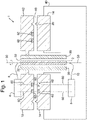
- Figure 1 is a schematic illustration (not to scale) of an ORJ installation.
- Figure 1 is a schematic illustration (not to scale) of an ORJ installation 1 (not in the accompanying claims).
- the ORJ installation 1 comprises an ORJ 2, a sensor system 4, a control module 6, a drive shaft 30, a rotating optical fibre 8, and a fixed optical fibre 10.
- the ORJ 2 On the rotating side of its rotational interface the ORJ 2 is optically coupled to the sensor system 4 via the rotating optical fibre 8.
- the ORJ 2 On the fixed side of its rotational interface the ORJ 2 is optically coupled to the control system 6 via the fixed optical fibre 10.
- the ORJ 2 allows optical signals to be passed between the sensor system 4 and the control system 6 (and vice-versa) via the rotating optical fibre 8 and the fixed optical fibre 10.
- the optical fibres 8, 10 are single mode optical fibres, and accordingly the ORJ 2 is an ORJ suitable for single mode fibres.
- the ORJ interface system 1 further comprises a rotating platform section 12 and a fixed platform section 14 which in combination mechanically provide the rotational interface 16 served by the ORJ 2 by virtue of the relative rotational motion of the rotating platform section 12 to the fixed platform section 14.
- the rotating platform 12 is mechanically coupled to the drive shaft 30, and the rotation of the rotating platform 12 relative to the fixed platform 14 is implemented by virtue of the drive shaft rotating compared to the fixed platform section 14.
- the drive shaft 30 is coupled to a geared spindle 104 of a motor 106 by means of a gearing 102 applied to the external surface of the shaft 30, and thus the shaft 30 is operable to rotate under the influence of the motor 106. Consequently, the axis of rotation 50 is along the central radial axis of the drive shaft.
- the drive shaft 30 is hollowed out at its centre along the length of its axis that is parallel to the axis of rotation, i.e. the drive shaft 30 is provided with a hollow central bore 32.
- the ORJ 2 is provided in the hollow central bore 32 of the drive shaft 30 i.e. the ORJ 2 is positioned within the hollowed out central bore 32 of the drive shaft 30.
- the hollow central bore is provided by drilling or otherwise removing the central material from a previously formed solid drive shaft. This is advantageous when carrying out a retro fit procedure.
- the drive shaft with central hollow bore may be provided in other ways, for example by welding together two semi-circular wall sections to provide a hollow final assembled drive shaft.
- the movement of the rotating platform relative to the fixed platform 14 is further facilitated by bearings 20 positioned on the face of the fixed platform 14 that faces the rotating platform 12.
- the sensor system comprises a plurality of camera sensors.
- one or more other types of sensors may be employed in addition to or instead of camera sensors.
- apparatus other than sensors may have its optical signals communicated across the rotational interface 16 by the ORJ 2.
- the sensor system 4 is attached in a fixed manner to the rotating platform 12.
- control system 6 and fixed platform 14 are held in a fixed housing 40.
- electrical coupling is provided between the sensor system 4 and the control system 6 by electrical cables 60.
- the rotating platform 12 and the fixed platform 14 further comprise in combination a conventional electrical slip ring arrangement 62, often referred to as a pancake slip ring, for transferring electrical power being supplied along the electrical cables 60 over the rotational interface 16.
- control signals are delivered by the ORJ installation 1 from the control system 6 to the sensor system 4.
- reverse direction output e.g. video
- signals from the sensor system 4 are delivered by the ORJ installation 1 from the sensor system 4 to the control system 6.
- This delivery is via the following sequence of elements: the sensor system 4; the rotating optical fibre 8; the ORJ 2; the fixed optical fibre 10; and the control system 6 (and in the reverse order for the reverse direction).
- signals are passed in both directions across the ORJ.
- signals are only sent unidirectional, e.g. only control signals or only sensor output signals, or some other form of signal.
- the senor system is on a part that is conveniently considered as rotating relative to a fixed part.
- either (or both) entity may be considered as rotating compared to the other, and hence such terminology is not used in a limiting sense herein.
- the ORJ is used to communicate signals to and from camera sensors, however this need not be the case, and in other embodiments signals for or from other types of apparatus may be passed via the ORJ in addition to, or instead of, signals related to sensors. For example communications data and Radio Frequency transmit or receive signals may be passed through the ORJ.
- control system 6 may be arranged to forward the received output data to any desired further entities, for example video recorders, displays, and so on.
- control system 6 may be arranged to receive the control data or data from which it can determine control data from any desired further entities.
- ORJ there is only a single ORJ, and moreover the ORJ is a single-channel ORJ. However, this need not be the case, and in other embodiments multi-channel ORJs may be used instead.
- the ORJ (or in the case of the preceding paragraph multi-channel ORJs) is a single mode fibre ORJ.
- the external diameter of the drive shaft 30 is 25mm
- the diameter of the hollow central bore 32 is 16mm
- the external diameter of the ORJ 2 is 14mm (i.e. there is a total clearance between the ORJ 2 and the wall of the hollow central bore 32 of 2mm, distributed approximately as 1mm at each end of any given diameter).
- the hollowed out drive shaft retains about 60% of the cross-sectional area of the solid one and hence approximately its physical strength is retained or at least not catastrophically diminished.
- a drive shaft will only need to be widened a little to allow room for the hollow central bore if a given remaining cross-sectional area of shaft material were required when designing a new drive shaft.
- arrangements with the following ranges of dimensions are particularly advantageous:
- a further advantage of providing the ORJ in a hollow central bore of the drive shaft is that other design details, such as the annularly positioned slip rings (i.e. external to the hollow drive shaft), the bearings, and so on, do not need to be changed.
- This is particularly advantageous when a retro-fit is carried out, i.e. an existing solid drive shaft is hollowed out (or replaced by a similar drive shaft that is however hollow) to allow an ORJ to be provided at a rotating interface arrangement that previously did not have optical signal capability.
- This is particularly advantageous when used to provide higher bandwidth capability to an arrangement, which may for example become required or desirable due to ever-increasing data flow requirements produced by the emergence of higher bandwidth cameras and so on.
Landscapes
- Physics & Mathematics (AREA)
- General Physics & Mathematics (AREA)
- Optics & Photonics (AREA)
- Electromagnetism (AREA)
- Engineering & Computer Science (AREA)
- Computer Networks & Wireless Communication (AREA)
- Signal Processing (AREA)
- Shafts, Cranks, Connecting Bars, And Related Bearings (AREA)
- Mechanical Coupling Of Light Guides (AREA)
- Rolling Contact Bearings (AREA)
- Optical Couplings Of Light Guides (AREA)
Description
- The present invention relates to the provision of an optical rotating joint installation.
- Conventionally, in order to convey signals across an interface between two physical entities, where at least one of the physical entities is rotating, electrical slip rings are employed.
- Conventionally, when the drive mechanism for the physical interface is provided by an off-axis gear mechanism, an optical rotating joint (ORJ), also known as a fibre optic rotary joint (FORJ) can additionally (or alternatively) be positioned along the axis of rotation to allow optical signals to be passed across the rotating interface. One type of ORJ is a single channel single-mode ORJ, i.e. one in which optical signals are transmitted across the rotating interface from one fixed single-mode optical fibre to one rotating single-mode optical fibre.
- Conventionally however, when the when drive mechanism for the physical interface is provided by a substantially central drive shaft, this is considered to be an insurmountable obstacle, or at least a significant impediment, to the inclusion of an ORJ, at least one positioned along the axis of rotation. It is noted that, in contrast, slip rings are not affected by this as they are in an annular form, and hence do not require to be, and would tend not to benefit from, being positioned along the axis of rotation.
EP0982608 ,US20050069250 andUS6434293 specify various forms of rotating optical joint. - The present inventors have realised that contrary to conventional approaches and considerations, in particular the established view that an ORJ cannot be provided along the axis of rotation when there is a substantially central drive shaft, this is in fact possible and can be implemented by use of aspects of their invention.
- Moreover the present inventors have further realised that the functionality and key properties of a substantially central drive shaft can be retained either completely or at least to a significant extent whilst nevertheless providing an ORJ positioned along the axis of rotation by means of aspects of their invention.
- In a further aspect, the present invention provides a method according to claim 1. the method comprises: providing a drive shaft comprising a hollow central bore; and providing an optical rotating joint located in the hollow central bore.
- The optical rotating joint installation is provided as a retro-fit to replace an existing solid drive shaft that does not have an optical rotating joint.
- The drive shaft with a hollow central bore may be provided by hollowing out the existing solid drive shaft.
- The drive shaft with a hollow central bore may be provided by replacing the existing solid drive shaft with a drive shaft with a hollow central bore.
- The proportion of the cross-sectional area of the material retained in the annular section of the drive shaft when the hollow central bore is provided compared to if the drive shaft were of solid-cross section may be greater than or equal to 50%.
- The proportion of the cross-sectional area of the material retained in the annular section of the drive shaft when the hollow central bore is provided compared to if the drive shaft were of solid-cross section may be greater than or equal to 60%.
- The proportion of the cross-sectional area of the material retained in the annular section of the drive shaft when the hollow central bore is provided compared to if the drive shaft were of solid-cross section may be greater than or equal to 75%.
- The diameter of the hollow central bore may be less than or equal to 20mm.
- The diameter of the hollow central bore may be less than or equal to 16mm.
-
Figure 1 is a schematic illustration (not to scale) of an ORJ installation. -
Figure 1 is a schematic illustration (not to scale) of an ORJ installation 1 (not in the accompanying claims). - In the following description, the terminology "a rotating ..."and "a fixed ..." is used as a form of annotation for ease of reference to allow the reader to readily appreciate which elements in the particular embodiments described below are on the rotating side of the overall arrangement and which are on the fixed side. It will be appreciated that such terminology is merely used for identification purposes, and does not specify or imply any intrinsic rotation or otherwise (other than by virtue of being on the main rotating platform or not on it) of the particular element so identified.
- The ORJ installation 1 comprises an
ORJ 2, asensor system 4, acontrol module 6, adrive shaft 30, a rotatingoptical fibre 8, and a fixedoptical fibre 10. On the rotating side of its rotational interface the ORJ 2 is optically coupled to thesensor system 4 via the rotatingoptical fibre 8. On the fixed side of its rotational interface the ORJ 2 is optically coupled to thecontrol system 6 via the fixedoptical fibre 10. In operation the ORJ 2 allows optical signals to be passed between thesensor system 4 and the control system 6 (and vice-versa) via the rotatingoptical fibre 8 and the fixedoptical fibre 10. In this embodiment theoptical fibres - In this embodiment the ORJ interface system 1 further comprises a
rotating platform section 12 and afixed platform section 14 which in combination mechanically provide therotational interface 16 served by the ORJ 2 by virtue of the relative rotational motion of therotating platform section 12 to thefixed platform section 14. Therotating platform 12 is mechanically coupled to thedrive shaft 30, and the rotation of therotating platform 12 relative to thefixed platform 14 is implemented by virtue of the drive shaft rotating compared to thefixed platform section 14. Thedrive shaft 30 is coupled to a geared spindle 104 of a motor 106 by means of a gearing 102 applied to the external surface of theshaft 30, and thus theshaft 30 is operable to rotate under the influence of the motor 106. Consequently, the axis ofrotation 50 is along the central radial axis of the drive shaft. - The
drive shaft 30 is hollowed out at its centre along the length of its axis that is parallel to the axis of rotation, i.e. thedrive shaft 30 is provided with a hollowcentral bore 32. The ORJ 2 is provided in the hollowcentral bore 32 of thedrive shaft 30 i.e. the ORJ 2 is positioned within the hollowed outcentral bore 32 of thedrive shaft 30. In this embodiment the hollow central bore is provided by drilling or otherwise removing the central material from a previously formed solid drive shaft. This is advantageous when carrying out a retro fit procedure. However, in other embodiments the drive shaft with central hollow bore may be provided in other ways, for example by welding together two semi-circular wall sections to provide a hollow final assembled drive shaft. - The movement of the rotating platform relative to the
fixed platform 14 is further facilitated bybearings 20 positioned on the face of thefixed platform 14 that faces therotating platform 12. - In this embodiment the sensor system comprises a plurality of camera sensors. In other embodiments one or more other types of sensors may be employed in addition to or instead of camera sensors. Indeed, in yet further embodiments, apparatus other than sensors may have its optical signals communicated across the
rotational interface 16 by the ORJ 2. Thesensor system 4 is attached in a fixed manner to therotating platform 12. - The
control system 6 andfixed platform 14 are held in afixed housing 40. - In this embodiment, electrical coupling is provided between the
sensor system 4 and thecontrol system 6 byelectrical cables 60. Therotating platform 12 and thefixed platform 14 further comprise in combination a conventional electricalslip ring arrangement 62, often referred to as a pancake slip ring, for transferring electrical power being supplied along theelectrical cables 60 over therotational interface 16. - In this embodiment, in operation, control signals are delivered by the ORJ installation 1 from the
control system 6 to thesensor system 4. In the reverse direction output (e.g. video) signals from thesensor system 4 are delivered by the ORJ installation 1 from thesensor system 4 to thecontrol system 6. This delivery is via the following sequence of elements: thesensor system 4; the rotatingoptical fibre 8; theORJ 2; the fixedoptical fibre 10; and the control system 6 (and in the reverse order for the reverse direction). - In this embodiment signals are passed in both directions across the ORJ. However, this need not be the case, and in other embodiments signals are only sent unidirectional, e.g. only control signals or only sensor output signals, or some other form of signal.
- In this embodiment the sensor system is on a part that is conveniently considered as rotating relative to a fixed part. However, clearly when there is relative rotation either (or both) entity may be considered as rotating compared to the other, and hence such terminology is not used in a limiting sense herein.
- In this embodiment the ORJ is used to communicate signals to and from camera sensors, however this need not be the case, and in other embodiments signals for or from other types of apparatus may be passed via the ORJ in addition to, or instead of, signals related to sensors. For example communications data and Radio Frequency transmit or receive signals may be passed through the ORJ.
- In this embodiment, the
control system 6 may be arranged to forward the received output data to any desired further entities, for example video recorders, displays, and so on. Correspondingly, thecontrol system 6 may be arranged to receive the control data or data from which it can determine control data from any desired further entities. - In this embodiment there is only a single ORJ, and moreover the ORJ is a single-channel ORJ. However, this need not be the case, and in other embodiments multi-channel ORJs may be used instead.
- In this embodiment the ORJ (or in the case of the preceding paragraph multi-channel ORJs) is a single mode fibre ORJ. However, this need not be the case, and in other embodiments one or more multi-mode fibre ORJs may be used instead or in addition to a single mode fibre ORJ.
- In this embodiment the external diameter of the
drive shaft 30 is 25mm, the diameter of the hollowcentral bore 32 is 16mm, and the external diameter of theORJ 2 is 14mm (i.e. there is a total clearance between theORJ 2 and the wall of the hollow central bore 32 of 2mm, distributed approximately as 1mm at each end of any given diameter). By virtue of sizes such as these, the benefits of using an ORJ positioned along the axis of rotation are achieved whilst nevertheless using a central drive shaft to provide the mechanical rotation, with the mechanical properties of the central drive shaft being relatively unaffected. For example, the remaining cross-sectional area of the annulus of material of thedrive shaft 30 in this embodiment is -π(12.52-82) mm2 = π x 92.25 mm2, whereas the cross-sectional area that the same drive shaft would have had were it not hollowed out is π x 12.52 mm2= π x 156.25 mm2, i.e. in this embodiment the hollowed out drive shaft retains about 60% of the cross-sectional area of the solid one and hence approximately its physical strength is retained or at least not catastrophically diminished. Or, considered in a different sense, a drive shaft will only need to be widened a little to allow room for the hollow central bore if a given remaining cross-sectional area of shaft material were required when designing a new drive shaft. In view of such considerations, arrangements with the following ranges of dimensions are particularly advantageous: - Proportion of the cross-sectional area of the material retained in the annular section of the drive shaft when a hollow central bore is provided compared to if the drive shaft were of solid-cross section, i.e. with no bore:
- (i) preferably greater than or equal to 50%;
- (ii) more preferably greater than or equal to 60%;
- (iii) yet more preferably greater than or equal to 75%.
- Diameter of the hollow central bore 32:
- (i) preferably less than or equal to 20mm;
- (ii) more preferably less than or equal to 16mm;
- (iii) yet more preferably less than or equal to 10mm.
- A further advantage of providing the ORJ in a hollow central bore of the drive shaft is that other design details, such as the annularly positioned slip rings (i.e. external to the hollow drive shaft), the bearings, and so on, do not need to be changed. This is particularly advantageous when a retro-fit is carried out, i.e. an existing solid drive shaft is hollowed out (or replaced by a similar drive shaft that is however hollow) to allow an ORJ to be provided at a rotating interface arrangement that previously did not have optical signal capability. This is particularly advantageous when used to provide higher bandwidth capability to an arrangement, which may for example become required or desirable due to ever-increasing data flow requirements produced by the emergence of higher bandwidth cameras and so on.
Claims (7)
- A method of providing a retro-fit optical rotating joint installation; the method comprising:i) Providing a rotating installation comprisinga first platforma second platforma drive shaft arranged at a rotating interface between the first and second platform, the drive shaft being fixed to the first platform and rotatably mounted in the second platformii) providing that the drive shaft comprises a hollow central bore; andiii) providing an optical rotating joint located in the hollow central boreiv) providing an annularly positioned pancake slip ring between the first platform and the second platform and external to the shaft,wherein the optical rotating joint installation is provided as a retro-fit to replace an existing solid drive shaft that does not have an optical rotating joint.
- A method according to claim 1, wherein the drive shaft with a hollow central bore is provided by hollowing out the existing solid drive shaft.
- A method according to claim 1, wherein the drive shaft with a hollow central bore is provided by replacing the existing solid drive shaft with a drive shaft with a hollow central bore.
- A method according to any of claims 1 to 3, wherein the proportion of the cross-sectional area of the material retained in the annular section of the drive shaft when the hollow central bore is provided compared to if the drive shaft were of solid-cross section is greater than or equal to 50%.
- A method according to claim 4, wherein the proportion of the cross-sectional area of the material retained in the annular section of the drive shaft when the hollow central bore is provided compared to if the drive shaft were of solid-cross section is greater than or equal to 60%.
- A method according to claim 5, wherein the proportion of the cross-sectional area of the material retained in the annular section of the drive shaft when the hollow central bore is provided compared to if the drive shaft were of solid-cross section is greater than or equal to 75%.
- A method according to any of claims 1 to 6, wherein the diameter of the hollow central bore is less than or equal to 20mm.
Applications Claiming Priority (2)
| Application Number | Priority Date | Filing Date | Title |
|---|---|---|---|
| GB1217063.5A GB2506192A (en) | 2012-09-25 | 2012-09-25 | Optical rotating joint having drive shaft with a hollow central bore |
| PCT/GB2013/052492 WO2014049343A1 (en) | 2012-09-25 | 2013-09-24 | Provision of an optical rotating joint installation |
Publications (3)
| Publication Number | Publication Date |
|---|---|
| EP2901187A1 EP2901187A1 (en) | 2015-08-05 |
| EP2901187B1 EP2901187B1 (en) | 2020-04-22 |
| EP2901187B2 true EP2901187B2 (en) | 2022-11-02 |
Family
ID=47190540
Family Applications (1)
| Application Number | Title | Priority Date | Filing Date |
|---|---|---|---|
| EP13771182.6A Active EP2901187B2 (en) | 2012-09-25 | 2013-09-24 | Provision of an optical rotating joint installation |
Country Status (6)
| Country | Link |
|---|---|
| US (1) | US9551840B2 (en) |
| EP (1) | EP2901187B2 (en) |
| AU (1) | AU2013322334B2 (en) |
| CA (1) | CA2886034C (en) |
| GB (1) | GB2506192A (en) |
| WO (1) | WO2014049343A1 (en) |
Families Citing this family (2)
| Publication number | Priority date | Publication date | Assignee | Title |
|---|---|---|---|---|
| GB2506192A (en) | 2012-09-25 | 2014-03-26 | Bae Systems Plc | Optical rotating joint having drive shaft with a hollow central bore |
| RU2619796C1 (en) * | 2016-05-25 | 2017-05-18 | АКЦИОНЕРНОЕ ОБЩЕСТВО "Научно-исследовательский институт оптико-электронного приборостроения" (АО "НИИ ОЭП") | Device for information transmission |
Citations (3)
| Publication number | Priority date | Publication date | Assignee | Title |
|---|---|---|---|---|
| EP1134600A1 (en) † | 2000-03-14 | 2001-09-19 | Morgan-Rekofa GmbH & Co. KG | Multiple path rotary optical connector |
| CN101221269A (en) † | 2007-12-27 | 2008-07-16 | 浙江大学 | A new high-speed turntable based on optical fiber rotary connector |
| CN102522610A (en) † | 2011-12-22 | 2012-06-27 | 南京鑫轩电子系统工程有限公司 | Multichannel microwave rotary joint |
Family Cites Families (21)
| Publication number | Priority date | Publication date | Assignee | Title |
|---|---|---|---|---|
| FR2493534A1 (en) | 1980-10-31 | 1982-05-07 | Thomson Csf | Balanced turning couple abutment device for optical fibre - has rotating plate and alignment device interconnected by two degrees of freedom linkage perpendicular to axis of rotation |
| US4786136A (en) * | 1982-08-06 | 1988-11-22 | Iec Corporation | Optical fiber rotary coupler |
| DE4208140C2 (en) * | 1992-03-13 | 1995-02-09 | Rosenberger Hochfrequenztech | Rotary coupling for fiber optic cables |
| JP3129854B2 (en) * | 1992-10-07 | 2001-01-31 | 住友電気工業株式会社 | Optical switch device and alignment method thereof |
| GB9510829D0 (en) | 1995-05-22 | 1995-07-19 | Racal Mesl Radar Limited | Radio frequency coupler |
| US5553176A (en) * | 1995-07-14 | 1996-09-03 | The United States Of America As Represented By The Secretary Of The Navy | Single in-line fiber-optic rotary joint |
| JPH0933754A (en) * | 1995-07-25 | 1997-02-07 | Osaka Gas Co Ltd | Take-up device for optical fiber cable |
| US6628338B1 (en) * | 1998-07-08 | 2003-09-30 | Elbex Video Ltd. | Direct drive electric motor apparatus incorporating slip ring assembly |
| EP0982608A1 (en) * | 1998-08-21 | 2000-03-01 | Oerlikon Contraves Ag | Optical rotating coupler |
| JP2001044940A (en) * | 1999-07-27 | 2001-02-16 | Japan Servo Co Ltd | Rotary optical coupling device |
| US6980715B2 (en) * | 2003-09-29 | 2005-12-27 | The Boeing Company | Fiber optic rotary joint and method therefor |
| DE102006056682B4 (en) | 2006-01-13 | 2018-10-11 | Sew-Eurodrive Gmbh & Co Kg | System for contactless energy transfer |
| JP4985231B2 (en) * | 2006-09-14 | 2012-07-25 | 株式会社Jvcケンウッド | Rotary joint |
| US20140163664A1 (en) * | 2006-11-21 | 2014-06-12 | David S. Goldsmith | Integrated system for the ballistic and nonballistic infixion and retrieval of implants with or without drug targeting |
| DE102007042659C5 (en) | 2007-09-10 | 2016-01-21 | Sew-Eurodrive Gmbh & Co Kg | coupling device |
| WO2009105254A2 (en) * | 2008-02-20 | 2009-08-27 | Actioncam, Llc | Aerial camera system |
| JP2009236614A (en) * | 2008-03-26 | 2009-10-15 | Fujifilm Corp | Optical rotary adaptor and optical tomographic imaging apparatus using the same |
| CN100585439C (en) | 2008-08-28 | 2010-01-27 | 中航光电科技股份有限公司 | An optical fiber alignment component and a transfer type single-core optical fiber rotary connector |
| CN101644800B (en) | 2009-08-31 | 2011-07-13 | 中航光电科技股份有限公司 | Photoelectric composite-rotation connector |
| US9182070B2 (en) * | 2012-04-30 | 2015-11-10 | Threat Spectrum Inc. | Positioning device |
| GB2506192A (en) | 2012-09-25 | 2014-03-26 | Bae Systems Plc | Optical rotating joint having drive shaft with a hollow central bore |
-
2012
- 2012-09-25 GB GB1217063.5A patent/GB2506192A/en not_active Withdrawn
-
2013
- 2013-09-24 AU AU2013322334A patent/AU2013322334B2/en active Active
- 2013-09-24 WO PCT/GB2013/052492 patent/WO2014049343A1/en not_active Ceased
- 2013-09-24 CA CA2886034A patent/CA2886034C/en active Active
- 2013-09-24 US US14/430,835 patent/US9551840B2/en active Active
- 2013-09-24 EP EP13771182.6A patent/EP2901187B2/en active Active
Patent Citations (3)
| Publication number | Priority date | Publication date | Assignee | Title |
|---|---|---|---|---|
| EP1134600A1 (en) † | 2000-03-14 | 2001-09-19 | Morgan-Rekofa GmbH & Co. KG | Multiple path rotary optical connector |
| CN101221269A (en) † | 2007-12-27 | 2008-07-16 | 浙江大学 | A new high-speed turntable based on optical fiber rotary connector |
| CN102522610A (en) † | 2011-12-22 | 2012-06-27 | 南京鑫轩电子系统工程有限公司 | Multichannel microwave rotary joint |
Non-Patent Citations (1)
| Title |
|---|
| Motion Technology Catalog, Slip Flings, Fiber Optic Rotary Joints, MOOG COMPONENTS GROUP, 2004 † |
Also Published As
| Publication number | Publication date |
|---|---|
| CA2886034A1 (en) | 2014-04-03 |
| GB201217063D0 (en) | 2012-11-07 |
| GB2506192A (en) | 2014-03-26 |
| CA2886034C (en) | 2021-01-05 |
| WO2014049343A1 (en) | 2014-04-03 |
| US20150253512A1 (en) | 2015-09-10 |
| AU2013322334B2 (en) | 2017-07-13 |
| US9551840B2 (en) | 2017-01-24 |
| EP2901187B1 (en) | 2020-04-22 |
| AU2013322334A1 (en) | 2015-04-09 |
| EP2901187A1 (en) | 2015-08-05 |
Similar Documents
| Publication | Publication Date | Title |
|---|---|---|
| US7515782B2 (en) | Two-channel, dual-mode, fiber optic rotary joint | |
| JP7106550B2 (en) | Systems and methods for providing optical rotary joints | |
| CN100585439C (en) | An optical fiber alignment component and a transfer type single-core optical fiber rotary connector | |
| US8301030B2 (en) | Rotary joint | |
| CN110170988A (en) | Gear for robot arm encapsulates | |
| EP1187152A2 (en) | Rotary contactless connector and non-rotary contactless connector | |
| EP2901187B2 (en) | Provision of an optical rotating joint installation | |
| US20120207430A1 (en) | Active off-axis fiber optic slip ring | |
| CN201051162Y (en) | Multi-channel free space optical inter-connector | |
| CN101334507B (en) | Plastic Optical Fiber Rotary Connector | |
| US8983246B2 (en) | Rotary optical link joint | |
| US4786136A (en) | Optical fiber rotary coupler | |
| EP1143274A2 (en) | Multi-channel on-axis fiber optic rotary joint | |
| CA2926201C (en) | Fiber optic rotary joint connecting dual-core fibers | |
| US6819854B1 (en) | Fiber optic rotary flex | |
| EP3904929B1 (en) | Hollow shaft optical rotary joint | |
| CN216210149U (en) | Collimator fixing device, optical fiber slip ring and imaging system of optical fiber slip ring | |
| CN1380562A (en) | Multi-channel optical fibre two-way transmission turning connector | |
| US11237337B1 (en) | Non-rotary joint | |
| JP5371406B2 (en) | Assembly of two components that can rotate relative to each other | |
| WO2022024910A1 (en) | Bearing device | |
| CN212848840U (en) | Environment monitoring information feedback antenna | |
| CN201060290Y (en) | Plastic Optical Fiber Rotary Connector | |
| JP2016151743A (en) | Optical rotary connector | |
| JP2021048434A (en) | PTZ mechanism with signal transmitter |
Legal Events
| Date | Code | Title | Description |
|---|---|---|---|
| PUAI | Public reference made under article 153(3) epc to a published international application that has entered the european phase |
Free format text: ORIGINAL CODE: 0009012 |
|
| 17P | Request for examination filed |
Effective date: 20150421 |
|
| AK | Designated contracting states |
Kind code of ref document: A1 Designated state(s): AL AT BE BG CH CY CZ DE DK EE ES FI FR GB GR HR HU IE IS IT LI LT LU LV MC MK MT NL NO PL PT RO RS SE SI SK SM TR |
|
| AX | Request for extension of the european patent |
Extension state: BA ME |
|
| DAX | Request for extension of the european patent (deleted) | ||
| STAA | Information on the status of an ep patent application or granted ep patent |
Free format text: STATUS: EXAMINATION IS IN PROGRESS |
|
| 17Q | First examination report despatched |
Effective date: 20190409 |
|
| GRAP | Despatch of communication of intention to grant a patent |
Free format text: ORIGINAL CODE: EPIDOSNIGR1 |
|
| STAA | Information on the status of an ep patent application or granted ep patent |
Free format text: STATUS: GRANT OF PATENT IS INTENDED |
|
| INTG | Intention to grant announced |
Effective date: 20191212 |
|
| GRAS | Grant fee paid |
Free format text: ORIGINAL CODE: EPIDOSNIGR3 |
|
| GRAA | (expected) grant |
Free format text: ORIGINAL CODE: 0009210 |
|
| STAA | Information on the status of an ep patent application or granted ep patent |
Free format text: STATUS: THE PATENT HAS BEEN GRANTED |
|
| AK | Designated contracting states |
Kind code of ref document: B1 Designated state(s): AL AT BE BG CH CY CZ DE DK EE ES FI FR GB GR HR HU IE IS IT LI LT LU LV MC MK MT NL NO PL PT RO RS SE SI SK SM TR |
|
| REG | Reference to a national code |
Ref country code: GB Ref legal event code: FG4D |
|
| REG | Reference to a national code |
Ref country code: CH Ref legal event code: EP |
|
| REG | Reference to a national code |
Ref country code: IE Ref legal event code: FG4D |
|
| REG | Reference to a national code |
Ref country code: DE Ref legal event code: R096 Ref document number: 602013068186 Country of ref document: DE |
|
| REG | Reference to a national code |
Ref country code: AT Ref legal event code: REF Ref document number: 1260878 Country of ref document: AT Kind code of ref document: T Effective date: 20200515 |
|
| REG | Reference to a national code |
Ref country code: NO Ref legal event code: T2 Effective date: 20200422 |
|
| REG | Reference to a national code |
Ref country code: NL Ref legal event code: FP |
|
| REG | Reference to a national code |
Ref country code: SE Ref legal event code: TRGR |
|
| REG | Reference to a national code |
Ref country code: LT Ref legal event code: MG4D |
|
| PG25 | Lapsed in a contracting state [announced via postgrant information from national office to epo] |
Ref country code: IS Free format text: LAPSE BECAUSE OF FAILURE TO SUBMIT A TRANSLATION OF THE DESCRIPTION OR TO PAY THE FEE WITHIN THE PRESCRIBED TIME-LIMIT Effective date: 20200822 Ref country code: FI Free format text: LAPSE BECAUSE OF FAILURE TO SUBMIT A TRANSLATION OF THE DESCRIPTION OR TO PAY THE FEE WITHIN THE PRESCRIBED TIME-LIMIT Effective date: 20200422 Ref country code: PT Free format text: LAPSE BECAUSE OF FAILURE TO SUBMIT A TRANSLATION OF THE DESCRIPTION OR TO PAY THE FEE WITHIN THE PRESCRIBED TIME-LIMIT Effective date: 20200824 Ref country code: GR Free format text: LAPSE BECAUSE OF FAILURE TO SUBMIT A TRANSLATION OF THE DESCRIPTION OR TO PAY THE FEE WITHIN THE PRESCRIBED TIME-LIMIT Effective date: 20200723 Ref country code: LT Free format text: LAPSE BECAUSE OF FAILURE TO SUBMIT A TRANSLATION OF THE DESCRIPTION OR TO PAY THE FEE WITHIN THE PRESCRIBED TIME-LIMIT Effective date: 20200422 |
|
| REG | Reference to a national code |
Ref country code: AT Ref legal event code: MK05 Ref document number: 1260878 Country of ref document: AT Kind code of ref document: T Effective date: 20200422 |
|
| PG25 | Lapsed in a contracting state [announced via postgrant information from national office to epo] |
Ref country code: RS Free format text: LAPSE BECAUSE OF FAILURE TO SUBMIT A TRANSLATION OF THE DESCRIPTION OR TO PAY THE FEE WITHIN THE PRESCRIBED TIME-LIMIT Effective date: 20200422 Ref country code: BG Free format text: LAPSE BECAUSE OF FAILURE TO SUBMIT A TRANSLATION OF THE DESCRIPTION OR TO PAY THE FEE WITHIN THE PRESCRIBED TIME-LIMIT Effective date: 20200722 Ref country code: LV Free format text: LAPSE BECAUSE OF FAILURE TO SUBMIT A TRANSLATION OF THE DESCRIPTION OR TO PAY THE FEE WITHIN THE PRESCRIBED TIME-LIMIT Effective date: 20200422 Ref country code: HR Free format text: LAPSE BECAUSE OF FAILURE TO SUBMIT A TRANSLATION OF THE DESCRIPTION OR TO PAY THE FEE WITHIN THE PRESCRIBED TIME-LIMIT Effective date: 20200422 |
|
| PG25 | Lapsed in a contracting state [announced via postgrant information from national office to epo] |
Ref country code: AL Free format text: LAPSE BECAUSE OF FAILURE TO SUBMIT A TRANSLATION OF THE DESCRIPTION OR TO PAY THE FEE WITHIN THE PRESCRIBED TIME-LIMIT Effective date: 20200422 |
|
| REG | Reference to a national code |
Ref country code: DE Ref legal event code: R026 Ref document number: 602013068186 Country of ref document: DE |
|
| PLBI | Opposition filed |
Free format text: ORIGINAL CODE: 0009260 |
|
| PG25 | Lapsed in a contracting state [announced via postgrant information from national office to epo] |
Ref country code: DK Free format text: LAPSE BECAUSE OF FAILURE TO SUBMIT A TRANSLATION OF THE DESCRIPTION OR TO PAY THE FEE WITHIN THE PRESCRIBED TIME-LIMIT Effective date: 20200422 Ref country code: AT Free format text: LAPSE BECAUSE OF FAILURE TO SUBMIT A TRANSLATION OF THE DESCRIPTION OR TO PAY THE FEE WITHIN THE PRESCRIBED TIME-LIMIT Effective date: 20200422 Ref country code: EE Free format text: LAPSE BECAUSE OF FAILURE TO SUBMIT A TRANSLATION OF THE DESCRIPTION OR TO PAY THE FEE WITHIN THE PRESCRIBED TIME-LIMIT Effective date: 20200422 Ref country code: SM Free format text: LAPSE BECAUSE OF FAILURE TO SUBMIT A TRANSLATION OF THE DESCRIPTION OR TO PAY THE FEE WITHIN THE PRESCRIBED TIME-LIMIT Effective date: 20200422 Ref country code: IT Free format text: LAPSE BECAUSE OF FAILURE TO SUBMIT A TRANSLATION OF THE DESCRIPTION OR TO PAY THE FEE WITHIN THE PRESCRIBED TIME-LIMIT Effective date: 20200422 Ref country code: CZ Free format text: LAPSE BECAUSE OF FAILURE TO SUBMIT A TRANSLATION OF THE DESCRIPTION OR TO PAY THE FEE WITHIN THE PRESCRIBED TIME-LIMIT Effective date: 20200422 Ref country code: RO Free format text: LAPSE BECAUSE OF FAILURE TO SUBMIT A TRANSLATION OF THE DESCRIPTION OR TO PAY THE FEE WITHIN THE PRESCRIBED TIME-LIMIT Effective date: 20200422 Ref country code: ES Free format text: LAPSE BECAUSE OF FAILURE TO SUBMIT A TRANSLATION OF THE DESCRIPTION OR TO PAY THE FEE WITHIN THE PRESCRIBED TIME-LIMIT Effective date: 20200422 |
|
| PLAX | Notice of opposition and request to file observation + time limit sent |
Free format text: ORIGINAL CODE: EPIDOSNOBS2 |
|
| 26 | Opposition filed |
Opponent name: SCHLEIFRING GMBH Effective date: 20210120 |
|
| PG25 | Lapsed in a contracting state [announced via postgrant information from national office to epo] |
Ref country code: PL Free format text: LAPSE BECAUSE OF FAILURE TO SUBMIT A TRANSLATION OF THE DESCRIPTION OR TO PAY THE FEE WITHIN THE PRESCRIBED TIME-LIMIT Effective date: 20200422 Ref country code: SK Free format text: LAPSE BECAUSE OF FAILURE TO SUBMIT A TRANSLATION OF THE DESCRIPTION OR TO PAY THE FEE WITHIN THE PRESCRIBED TIME-LIMIT Effective date: 20200422 |
|
| PG25 | Lapsed in a contracting state [announced via postgrant information from national office to epo] |
Ref country code: MC Free format text: LAPSE BECAUSE OF FAILURE TO SUBMIT A TRANSLATION OF THE DESCRIPTION OR TO PAY THE FEE WITHIN THE PRESCRIBED TIME-LIMIT Effective date: 20200422 |
|
| REG | Reference to a national code |
Ref country code: CH Ref legal event code: PL |
|
| PG25 | Lapsed in a contracting state [announced via postgrant information from national office to epo] |
Ref country code: SI Free format text: LAPSE BECAUSE OF FAILURE TO SUBMIT A TRANSLATION OF THE DESCRIPTION OR TO PAY THE FEE WITHIN THE PRESCRIBED TIME-LIMIT Effective date: 20200422 |
|
| PLBB | Reply of patent proprietor to notice(s) of opposition received |
Free format text: ORIGINAL CODE: EPIDOSNOBS3 |
|
| REG | Reference to a national code |
Ref country code: BE Ref legal event code: MM Effective date: 20200930 |
|
| PG25 | Lapsed in a contracting state [announced via postgrant information from national office to epo] |
Ref country code: LU Free format text: LAPSE BECAUSE OF NON-PAYMENT OF DUE FEES Effective date: 20200924 |
|
| PG25 | Lapsed in a contracting state [announced via postgrant information from national office to epo] |
Ref country code: BE Free format text: LAPSE BECAUSE OF NON-PAYMENT OF DUE FEES Effective date: 20200930 Ref country code: CH Free format text: LAPSE BECAUSE OF NON-PAYMENT OF DUE FEES Effective date: 20200930 Ref country code: IE Free format text: LAPSE BECAUSE OF NON-PAYMENT OF DUE FEES Effective date: 20200924 Ref country code: LI Free format text: LAPSE BECAUSE OF NON-PAYMENT OF DUE FEES Effective date: 20200930 |
|
| PG25 | Lapsed in a contracting state [announced via postgrant information from national office to epo] |
Ref country code: TR Free format text: LAPSE BECAUSE OF FAILURE TO SUBMIT A TRANSLATION OF THE DESCRIPTION OR TO PAY THE FEE WITHIN THE PRESCRIBED TIME-LIMIT Effective date: 20200422 Ref country code: MT Free format text: LAPSE BECAUSE OF FAILURE TO SUBMIT A TRANSLATION OF THE DESCRIPTION OR TO PAY THE FEE WITHIN THE PRESCRIBED TIME-LIMIT Effective date: 20200422 Ref country code: CY Free format text: LAPSE BECAUSE OF FAILURE TO SUBMIT A TRANSLATION OF THE DESCRIPTION OR TO PAY THE FEE WITHIN THE PRESCRIBED TIME-LIMIT Effective date: 20200422 |
|
| PG25 | Lapsed in a contracting state [announced via postgrant information from national office to epo] |
Ref country code: MK Free format text: LAPSE BECAUSE OF FAILURE TO SUBMIT A TRANSLATION OF THE DESCRIPTION OR TO PAY THE FEE WITHIN THE PRESCRIBED TIME-LIMIT Effective date: 20200422 |
|
| PUAH | Patent maintained in amended form |
Free format text: ORIGINAL CODE: 0009272 |
|
| STAA | Information on the status of an ep patent application or granted ep patent |
Free format text: STATUS: PATENT MAINTAINED AS AMENDED |
|
| 27A | Patent maintained in amended form |
Effective date: 20221102 |
|
| AK | Designated contracting states |
Kind code of ref document: B2 Designated state(s): AL AT BE BG CH CY CZ DE DK EE ES FI FR GB GR HR HU IE IS IT LI LT LU LV MC MK MT NL NO PL PT RO RS SE SI SK SM TR |
|
| REG | Reference to a national code |
Ref country code: DE Ref legal event code: R102 Ref document number: 602013068186 Country of ref document: DE |
|
| REG | Reference to a national code |
Ref country code: NL Ref legal event code: FP |
|
| REG | Reference to a national code |
Ref country code: SE Ref legal event code: RPEO |
|
| REG | Reference to a national code |
Ref country code: NO Ref legal event code: TB2 |
|
| P01 | Opt-out of the competence of the unified patent court (upc) registered |
Effective date: 20230502 |
|
| PGFP | Annual fee paid to national office [announced via postgrant information from national office to epo] |
Ref country code: NL Payment date: 20250820 Year of fee payment: 13 |
|
| PGFP | Annual fee paid to national office [announced via postgrant information from national office to epo] |
Ref country code: DE Payment date: 20250820 Year of fee payment: 13 |
|
| PGFP | Annual fee paid to national office [announced via postgrant information from national office to epo] |
Ref country code: NO Payment date: 20250825 Year of fee payment: 13 |
|
| PGFP | Annual fee paid to national office [announced via postgrant information from national office to epo] |
Ref country code: GB Payment date: 20250820 Year of fee payment: 13 |
|
| PGFP | Annual fee paid to national office [announced via postgrant information from national office to epo] |
Ref country code: FR Payment date: 20250820 Year of fee payment: 13 |
|
| PGFP | Annual fee paid to national office [announced via postgrant information from national office to epo] |
Ref country code: SE Payment date: 20250820 Year of fee payment: 13 |