EP2901000B1 - Joint annulaire à co-action radiale - Google Patents
Joint annulaire à co-action radiale Download PDFInfo
- Publication number
- EP2901000B1 EP2901000B1 EP13842850.3A EP13842850A EP2901000B1 EP 2901000 B1 EP2901000 B1 EP 2901000B1 EP 13842850 A EP13842850 A EP 13842850A EP 2901000 B1 EP2901000 B1 EP 2901000B1
- Authority
- EP
- European Patent Office
- Prior art keywords
- ring portion
- sealing ring
- seal apparatus
- pair
- upper sealing
- Prior art date
- Legal status (The legal status is an assumption and is not a legal conclusion. Google has not performed a legal analysis and makes no representation as to the accuracy of the status listed.)
- Active
Links
Images


Classifications
-
- F—MECHANICAL ENGINEERING; LIGHTING; HEATING; WEAPONS; BLASTING
- F16—ENGINEERING ELEMENTS AND UNITS; GENERAL MEASURES FOR PRODUCING AND MAINTAINING EFFECTIVE FUNCTIONING OF MACHINES OR INSTALLATIONS; THERMAL INSULATION IN GENERAL
- F16J—PISTONS; CYLINDERS; SEALINGS
- F16J15/00—Sealings
- F16J15/16—Sealings between relatively-moving surfaces
- F16J15/34—Sealings between relatively-moving surfaces with slip-ring pressed against a more or less radial face on one member
- F16J15/3464—Mounting of the seal
-
- F—MECHANICAL ENGINEERING; LIGHTING; HEATING; WEAPONS; BLASTING
- F01—MACHINES OR ENGINES IN GENERAL; ENGINE PLANTS IN GENERAL; STEAM ENGINES
- F01D—NON-POSITIVE DISPLACEMENT MACHINES OR ENGINES, e.g. STEAM TURBINES
- F01D11/00—Preventing or minimising internal leakage of working-fluid, e.g. between stages
- F01D11/003—Preventing or minimising internal leakage of working-fluid, e.g. between stages by packing rings; Mechanical seals
-
- F—MECHANICAL ENGINEERING; LIGHTING; HEATING; WEAPONS; BLASTING
- F01—MACHINES OR ENGINES IN GENERAL; ENGINE PLANTS IN GENERAL; STEAM ENGINES
- F01D—NON-POSITIVE DISPLACEMENT MACHINES OR ENGINES, e.g. STEAM TURBINES
- F01D11/00—Preventing or minimising internal leakage of working-fluid, e.g. between stages
- F01D11/005—Sealing means between non relatively rotating elements
-
- F—MECHANICAL ENGINEERING; LIGHTING; HEATING; WEAPONS; BLASTING
- F01—MACHINES OR ENGINES IN GENERAL; ENGINE PLANTS IN GENERAL; STEAM ENGINES
- F01D—NON-POSITIVE DISPLACEMENT MACHINES OR ENGINES, e.g. STEAM TURBINES
- F01D25/00—Component parts, details, or accessories, not provided for in, or of interest apart from, other groups
- F01D25/24—Casings; Casing parts, e.g. diaphragms, casing fastenings
- F01D25/246—Fastening of diaphragms or stator-rings
-
- F—MECHANICAL ENGINEERING; LIGHTING; HEATING; WEAPONS; BLASTING
- F01—MACHINES OR ENGINES IN GENERAL; ENGINE PLANTS IN GENERAL; STEAM ENGINES
- F01D—NON-POSITIVE DISPLACEMENT MACHINES OR ENGINES, e.g. STEAM TURBINES
- F01D9/00—Stators
- F01D9/02—Nozzles; Nozzle boxes; Stator blades; Guide conduits, e.g. individual nozzles
- F01D9/04—Nozzles; Nozzle boxes; Stator blades; Guide conduits, e.g. individual nozzles forming ring or sector
- F01D9/041—Nozzles; Nozzle boxes; Stator blades; Guide conduits, e.g. individual nozzles forming ring or sector using blades
-
- F—MECHANICAL ENGINEERING; LIGHTING; HEATING; WEAPONS; BLASTING
- F05—INDEXING SCHEMES RELATING TO ENGINES OR PUMPS IN VARIOUS SUBCLASSES OF CLASSES F01-F04
- F05D—INDEXING SCHEME FOR ASPECTS RELATING TO NON-POSITIVE-DISPLACEMENT MACHINES OR ENGINES, GAS-TURBINES OR JET-PROPULSION PLANTS
- F05D2230/00—Manufacture
- F05D2230/60—Assembly methods
- F05D2230/64—Assembly methods using positioning or alignment devices for aligning or centring, e.g. pins
- F05D2230/642—Assembly methods using positioning or alignment devices for aligning or centring, e.g. pins using maintaining alignment while permitting differential dilatation
-
- F—MECHANICAL ENGINEERING; LIGHTING; HEATING; WEAPONS; BLASTING
- F05—INDEXING SCHEMES RELATING TO ENGINES OR PUMPS IN VARIOUS SUBCLASSES OF CLASSES F01-F04
- F05D—INDEXING SCHEME FOR ASPECTS RELATING TO NON-POSITIVE-DISPLACEMENT MACHINES OR ENGINES, GAS-TURBINES OR JET-PROPULSION PLANTS
- F05D2240/00—Components
- F05D2240/55—Seals
-
- F—MECHANICAL ENGINEERING; LIGHTING; HEATING; WEAPONS; BLASTING
- F05—INDEXING SCHEMES RELATING TO ENGINES OR PUMPS IN VARIOUS SUBCLASSES OF CLASSES F01-F04
- F05D—INDEXING SCHEME FOR ASPECTS RELATING TO NON-POSITIVE-DISPLACEMENT MACHINES OR ENGINES, GAS-TURBINES OR JET-PROPULSION PLANTS
- F05D2250/00—Geometry
- F05D2250/30—Arrangement of components
- F05D2250/31—Arrangement of components according to the direction of their main axis or their axis of rotation
- F05D2250/314—Arrangement of components according to the direction of their main axis or their axis of rotation the axes being inclined in relation to each other
Definitions
- the present disclosure generally relates to sealing between cylindrical components having large radial and axial displacements
- Turbine engine seals are subject to relatively high and cyclic temperature conditions, ranging from atmospheric to 871°C (1600°F).
- the cyclic temperature variation results in expansions and contractions of parts, including radial and axial displacements of seals within their seats.
- the temperature variation issue is compounded by a need to effectively seal between parts subject to high pressure differentials.
- a further sealing challenge as related to mid-turbine vanes is in sealing between surfaces that may not be symmetrically oriented relative to one another.
- a piston ring for accommodating large axial deflections.
- such a ring may require a relatively thick section to provide fairly tall and robust rails in at least one of the relatively movable components in order to provide a groove for capturing the ring and to provide an axial seal face about a full circumference in view of very high and dynamically undulating axial loads and displacements encountered.
- Such a thick full-hoop section may be subjected to extremely high stresses under the large thermal gradients common to the internal environment of a gas turbine engine.
- a ring seal apparatus for high temperature sealing is described as defined in claim 1.
- a ring seal apparatus and axial support structure for high temperature sealing of a circumferential gap between a pair of components is described as defined in claim 2.
- the outer or upper sealing ring portion and inner or lower sealing ring portion may be axially positioned side-by-side so that the coacting mating faces slide relative to each other at an angle to the radial faces of the ring portions when the ring seal apparatus is subject to thermal expansion and vibration.
- the obliquely angled mating faces may form a separate sealing interface between the outer or upper sealing ring portion and inner or lower sealing ring portion, in addition to the seal of the circumferential gap provided by the ring seal apparatus.
- the sealing interface between the outer or upper sealing ring portion and inner or lower sealing ring portion functions as a wedge to enhance radial sealing of the ring seal apparatus.
- the radial sealing of the ring seal apparatus is enhanced as a direct function of axial pressure between the coacting mating faces of the outer or upper sealing ring portion and inner or lower sealing ring portion.
- each of the outer or upper sealing ring portion and inner or lower sealing ring portion may be a component sealing surface.
- each component sealing surface may be defined by a rounded corner.
- At least three sealing contacts may be established between the ring seal and the component surfaces when the seals are applied to asymmetrically oriented component surfaces.
- a method of forming a ring seal apparatus may further include providing a pair of abutments on one of the components to axially retain the outer or upper sealing ring portion and inner or lower sealing ring portion.
- a method of forming a ring seal apparatus may further include providing the pair of abutments such that they define a peripheral slot adapted to axially retain the ring portions.
- a method of forming a ring seal apparatus may further include forming rounded corners on each ring portion to define enhanced component sealing surfaces.
- Intake air 12 (indicated by arrows) consists of an atmospheric airflow as may be required to support the successful operation of the gas turbine engine 10.
- the intake air 12 is pulled into the gas turbine engine 10 by fan blades 14, adapted to rotate within a fan case 16 on a multistage turbine shaft 15.
- the intake air 12 may be split into two paths; a first path may be provided via a bypass duct 18, which longitudinally and circumferentially encases the internal working components of the gas turbine engine 10.
- the so-called bypass air flowing through the bypass duct 18 may be employed for producing additional thrust in modern turbofan jet engines, and as those skilled in the art may appreciate.
- the second air path may be directed to and through an axial flow compressor 20, commonly called a low-pressure stage compressor. From the low-pressure stage compressor 20, the second air path may enter a high-pressure centrifugal compressor 22, where the air may be further compressed and then pushed out through a diffuser 24 into a high-pressure air plenum 26.
- a plurality of combustors 30 may surround the multistage turbine shaft 15; the combustors 30 may be situated just radially inwardly of the bypass duct 18. Each of the combustors 30 may be supplied fuel via fuel supply tubes 32. The combustors 30 may be perforated with a plurality of apertures 36 to permit entry of high-pressure air into the combustors 30. Ignition of the fuel takes place in the combustors 30, and the products of combustion in the form of highly expansive gases pass through nozzle guide vanes 40 and then through turbines 42 to develop flight-sustaining thrust.
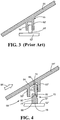
- a single piece resilient sealing ring 48 may provide sealing between the inner surface 50 of the case housing 44 and the outer shroud 52.
- a peripheral groove 46 has been employed for retention of the sealing ring 48.
- the single piece resilient sealing ring 48 has an outer extremity 54 which directly engages an inner surface 50 of the case housing 44, as well as radial faces 56 adapted to engage mating faces of a pair of axial retention abutments 58, 60.
- the axial retention abutments 58, 60 form the slot or peripheral groove 46 in which the seal 48 may be axially retained.
- seal 48' an enlarged view of such a prior art seal is depicted as seal 48' along with its associated mating components, including retention abutments 58' and 60' within which the seal 48' may be adapted to provide sealing between a turbine support case housing 44' and an outer shroud 52', as earlier described. It may be appreciated that any significant vibratory movements of the sealed components 44' and 52' may produce shifting and/or cocking of those components, which may at least occasionally challenge the capability of the seal 48' to effectively maintain a full sealing effect.
- the overall sealing structure of the prior art seal 48' has required a thickened full hoop region 55 in either of the components 44', 52' (in this case component 44') which may potentially give rise to problems due to the stress prone nature of significant thermal expansions and cyclic pressure fluctuations.
- the full hoop region 55 may be relatively expensive to manufacture.
- a modified turbine support case housing 44" may be employed to, among other benefits, avoid need for inclusion of the thickened full hoop region 55 of the case housing 44' of Figure 3 .
- a radially coacting sealing ring 70 may incorporate an outer or upper sealing ring portion 72, adapted to coact with a lower or inner sealing ring portion 74.
- Each of the sealing ring portions 72, 74 may include an oblique sealing face, such as oblique sealing face 80 situated on portion 72, and oblique sealing face 82 situated on portion 74.
- the oblique sealing faces 80, 82 may be adapted to matingly coact, and to seal more effectively over a wider range of thermal displacements that include relatively wide vertical cyclic separations between the case housing 44" and outer shroud 52".
- Region 66 (depicted as an arrow) is part of a high temperature combustion flow path.
- Region 68 (also depicted as an arrow) is a high-pressure cooler side of the case housing 44". It may be appreciated that the high-pressure region 68 will tend to force the radially coacting sealing ring 70 to the right in the view shown, and that appropriate sizing of the outer diameter 76 of outer ring portion 72 relative to the case housing 44" may be effective to create at least two circumferential sealing contact lines at all times i.e. between the ring portion 72 and axial retention abutment 60", as well as between the inner diameter 64 of the case housing 44" and the outer diameter 76 of the sealing ring portion 72.
- a line sealing contact may be more effectively achieved via the rounded corner 86 which defines one edge of the outside diameter 76 of the sealing ring portion 72. Such corner 86 may thus provide an enhanced component sealing surface.
- the inner diameter 78 of the inner or lower sealing ring portion 74 may be sized to sealingly engage the outside diameter 62 of the outer shroud 52".
- the inner diameter 78 of the ring portion 74 may also include rounded corners 88 to accommodate cocking and other asymmetric movements of the case housing 44" and outer shroud 52" components relative to one another. Such movements between components may be associated with extreme thermal variations, as well as actual temperature gradients, across the parts/components, as well as other factors including extreme turbulence, for example.
- the coacting mating oblique sealing faces 80, 82 combined with a sealing design adapted to more effectively accommodate larger vertical separations between the housing and shroud components 44" and 52", in environments of considerable vibration and temperature fluctuations that may result in expansion of parts, including that of the radially coacting sealing ring 70, may promote an inherently better sealing arrangement, particularly since at least three sealing contacts are established between the ring seal and the component surfaces when the seals are applied to asymmetrically oriented component surfaces.
- the sealing ring 70 may have each of its respective portions 72 and 74 formed of high temperature alloys, such as, but not limited to, Nickel, Inconel, e.g. Inconel 718 and Inconel 750, for example, and/or other metallurgical structures that exhibit great durability and strength at temperatures that may reach or its exceed 871°C (1600°F).
- high temperature alloys such as, but not limited to, Nickel, Inconel, e.g. Inconel 718 and Inconel 750, for example, and/or other metallurgical structures that exhibit great durability and strength at temperatures that may reach or its exceed 871°C (1600°F).
- each of the seal portions may be adapted to be positioned in relatively axial side-by-side positions with respect to the other for both radial and axial interaction via their obliquely angled mating surfaces
- each of the rings may be sized and adapted to more closely engage the respective components to be sealed.
- one of the ring portions may be adapted to seal radially on its outside diameter more closely with one of the cylindrical and/or conical components, while the other of the ring seals may be adapted to seal radially on its inside diameter more closely with the other component.
- the obliquely angled mating surfaces of the sealing portions may provide a sealing interface between the rings to function as a wedge for enhancement of radial sealing as a function of axial pressure between the rings seal portions.
Claims (13)
- Appareil d'étanchéité annulaire de turbine pour une étanchéité à haute température destiné à être utilisé avec un boîtier de carter de turbine (44") ayant une butée de retenue axiale (60") et un diamètre interne (64), l'appareil d'étanchéité annulaire comprenant : un anneau (70), ledit anneau comprenant
une partie annulaire d'étanchéité externe ou supérieure (72) comportant une paire de faces radiales, et un diamètre externe (76), dans lequel la partie annulaire d'étanchéité externe ou supérieure (72) et la butée de retenue axiale (60") sont en contact d'étanchéité circonférentiel et le diamètre externe (76) de la partie annulaire d'étanchéité externe ou supérieure (72) et le diamètre interne (64) du boîtier de carter de turbine (44") sont en contact d'étanchéité circonférentiel ; et
ledit anneau (70) comprenant en outre une partie annulaire d'étanchéité interne ou inférieure (74) comportant une seconde paire de faces radiales sensiblement parallèles à la première paire de faces radiales, la partie annulaire d'étanchéité interne ou inférieure (74) étant conçue pour co-agir avec la partie annulaire d'étanchéité externe ou supérieure (72), la partie annulaire d'étanchéité externe ou supérieure (72) et la partie annulaire d'étanchéité interne ou inférieure (74) définissant ensemble une paire de faces d'accouplement à co-action (80, 82), dans lequel les faces d'accouplement (80, 82) forment un angle oblique par rapport aux faces radiales, de sorte que chacune des faces d'accouplement à co-action (80, 82) est conçue pour assurer l'étanchéité d'une interface des deux parties annulaires (72, 74) selon un angle par rapport aux faces radiales, dans lequel la partie annulaire d'étanchéité externe ou supérieure (72) et la partie annulaire d'étanchéité interne ou inférieure (74) sont conçues pour assurer l'étanchéité d'un espace circonférentiel entre une paire de composants. - Appareil d'étanchéité annulaire de turbine et structure de support axial pour une étanchéité à haute température d'un espace circonférentiel entre une paire de composants destinés à être utilisés avec un boîtier de carter de turbine (44") ayant une butée de retenue axiale (60") et un diamètre interne (64), l'appareil d'étanchéité annulaire comprenant :un anneau (70), ledit anneau comprenant une partie annulaire d'étanchéité externe ou supérieure (72) comportant une paire de faces radiales et un diamètre externe (76), dans lequel la partie annulaire d'étanchéité externe ou supérieure (72) et la butée de retenue axiale (60") sont en contact d'étanchéité circonférentiel et le diamètre externe (76) de la partie annulaire d'étanchéité externe ou supérieure (72) et le diamètre interne (64) du boîtier de carter de turbine (44") sont en contact d'étanchéité circonférentiel ;ledit anneau (70) comprenant en outre une partie annulaire d'étanchéité interne ou inférieure (74) comportant une seconde paire de faces radiales sensiblement parallèles à la première paire de faces radiales, la partie annulaire d'étanchéité interne ou inférieure (74) étant conçue pour co-agir avec la partie annulaire d'étanchéité externe ou supérieure (72) ;la structure de support comprenant une paire de butées espacées axialement (58', 60') conçues pour retenir axialement la partie annulaire d'étanchéité externe ou supérieure (72) et la partie annulaire d'étanchéité interne ou inférieure (74) ; etla partie annulaire d'étanchéité externe ou supérieure (72) et la partie annulaire d'étanchéité interne ou inférieure (74) définissant ensemble une paire de faces d'accouplement à co-action (80, 82), dans lequel les faces d'accouplement (80, 82) forment un angle oblique par rapport aux faces radiales, de sorte que chacune des faces d'accouplement (80, 82) est conçue pour coulisser selon un angle par rapport aux faces radiales, dans lequel la paire de parties annulaires à co-action est conçue pour assurer l'étanchéité de l'espace circonférentiel entre les composants, et dans lequel les butées (58', 60') sont fixées à l'un des composants alignés.
- Appareil d'étanchéité annulaire (70) ou appareil d'étanchéité annulaire (70) et structure de support axial selon la revendication 1 ou 2, dans lesquels la partie annulaire d'étanchéité externe ou supérieure (72) et la partie annulaire d'étanchéité interne ou inférieure (74) sont positionnées axialement côte à côte, de sorte que les faces d'accouplement à co-action (80, 82) sont conçues pour coulisser l'une par rapport à l'autre selon un angle par rapport aux faces radiales des parties annulaires (72, 74) lorsque l'appareil d'étanchéité annulaire est soumis à une dilatation thermique et aux vibrations.
- Appareil d'étanchéité annulaire ou appareil d'étanchéité annulaire et structure de support axial selon une quelconque revendication précédente, dans lesquels les faces d'accouplement inclinées de manière oblique (80, 82) comprennent une interface d'étanchéité séparée entre la partie annulaire d'étanchéité externe ou supérieure (72) et la partie annulaire d'étanchéité interne ou inférieure (74) en plus du joint de l'espace circonférentiel prévu par l'appareil d'étanchéité annulaire.
- Appareil d'étanchéité annulaire ou appareil d'étanchéité annulaire et structure de support axial selon une quelconque revendication précédente, dans lesquels l'interface d'étanchéité entre la partie annulaire d'étanchéité externe ou supérieure (72) et la partie annulaire d'étanchéité interne ou inférieure (74) est conçue pour fonctionner comme un coin pour améliorer l'étanchéité radiale de l'appareil d'étanchéité annulaire.
- Appareil d'étanchéité annulaire ou appareil d'étanchéité annulaire et structure de support axial selon une quelconque revendication précédente, dans lesquels l'étanchéité radiale est améliorée directement en fonction de la pression axiale entre les faces d'accouplement à co-action (80, 82) de la partie annulaire d'étanchéité externe ou supérieure (72) et de la partie annulaire d'étanchéité interne ou inférieure (74).
- Appareil d'étanchéité annulaire ou appareil d'étanchéité annulaire et structure de support axial selon une quelconque revendication précédente, dans lesquels chacune de la partie annulaire d'étanchéité externe ou supérieure (72) et de la partie annulaire d'étanchéité interne ou inférieure (74) définit une surface d'étanchéité de composant.
- Appareil d'étanchéité annulaire ou appareil d'étanchéité annulaire et structure de support axial selon la revendication 7, dans lesquels chaque surface d'étanchéité de composant est définie par un coin arrondi (86, 88).
- Appareil d'étanchéité annulaire ou appareil d'étanchéité annulaire et structure de support axial selon une quelconque revendication précédente, dans lesquels, lorsque les joints d'étanchéité sont appliqués à des surfaces de composant orientées de manière asymétrique, au moins trois contacts d'étanchéité sont établis entre le joint annulaire et les surfaces de composant.
- Procédé pour assurer l'étanchéité d'un espace circonférentiel entre des composants de turbine, avec un boîtier de carter de turbine (44) ayant une butée de retenue axiale et un diamètre interne, le procédé comprenant :la formation d'un appareil d'étanchéité annulaire (70) comportant la formation d'un anneau comportant une partie annulaire d'étanchéité externe ou supérieure (72) ayant une paire de faces radiales ; etla formation d'une partie annulaire d'étanchéité interne ou inférieure (74) ayant une seconde paire de faces radiales, ladite partie annulaire d'étanchéité externe ou supérieure (72) ayant un diamètre externe (76), dans lequel la partie annulaire d'étanchéité externe ou supérieure (72) et la butée de retenue axiale (60") sont en contact d'étanchéité circonférentiel et le diamètre externe (76) de la partie annulaire d'étanchéité externe ou supérieure (72) et le diamètre interne (64) du boîtier de carter de turbine (44") sont en contact d'étanchéité circonférentiel ;la formation d'une face inclinée de manière oblique dans chacune de la partie annulaire d'étanchéité externe ou supérieure (72) et de la partie annulaire d'étanchéité interne ou inférieure (74) pour définir une paire de faces d'accouplement à co-action (80, 82) par rapport aux faces radiales de chaque partie annulaire, de sorte que chacune des faces d'accouplement (80, 82) est conçue pour coulisser selon un angle par rapport aux faces radiales ; etla juxtaposition de la partie annulaire d'étanchéité externe ou supérieure (72) et de la partie annulaire d'étanchéité interne ou inférieure (74) axialement côte à côte de sorte que leurs faces d'accouplement à co-action (80, 82) sont conçues pour assurer l'étanchéité d'un espace circonférentiel entre des composants alignés de manière asymétrique.
- Procédé selon la revendication 10, comprenant en outre la fourniture d'une paire de butées (58', 60') sur l'un des composants pour retenir axialement la partie annulaire d'étanchéité externe ou supérieure (72) et la partie annulaire d'étanchéité interne ou inférieure (74).
- Procédé selon la revendication 11, dans lequel la paire de butées (58', 60') définit une fente périphérique conçue pour retenir axialement les parties annulaires.
- Procédé selon la revendication 10, 11 ou 12, comprenant en outre la formation de coins arrondis (86, 88) sur chaque partie annulaire pour définir des surfaces d'étanchéité de composant améliorées.
Applications Claiming Priority (2)
| Application Number | Priority Date | Filing Date | Title |
|---|---|---|---|
| US201261707514P | 2012-09-28 | 2012-09-28 | |
| PCT/US2013/032605 WO2014051700A1 (fr) | 2012-09-28 | 2013-03-15 | Joint annulaire à co-action radiale |
Publications (3)
| Publication Number | Publication Date |
|---|---|
| EP2901000A1 EP2901000A1 (fr) | 2015-08-05 |
| EP2901000A4 EP2901000A4 (fr) | 2016-07-27 |
| EP2901000B1 true EP2901000B1 (fr) | 2019-10-09 |
Family
ID=50388848
Family Applications (1)
| Application Number | Title | Priority Date | Filing Date |
|---|---|---|---|
| EP13842850.3A Active EP2901000B1 (fr) | 2012-09-28 | 2013-03-15 | Joint annulaire à co-action radiale |
Country Status (3)
| Country | Link |
|---|---|
| US (1) | US9797515B2 (fr) |
| EP (1) | EP2901000B1 (fr) |
| WO (1) | WO2014051700A1 (fr) |
Families Citing this family (25)
| Publication number | Priority date | Publication date | Assignee | Title |
|---|---|---|---|---|
| EP3027870B1 (fr) * | 2013-08-02 | 2019-05-15 | United Technologies Corporation | Dispositif d'étanchéité cunéiforme à structures non rotatives d'un moteur à turbine à gaz |
| US9759427B2 (en) * | 2013-11-01 | 2017-09-12 | General Electric Company | Interface assembly for a combustor |
| US9945295B2 (en) * | 2015-06-01 | 2018-04-17 | United Technologies Corporation | Composite piston ring seal for axially and circumferentially translating ducts |
| US10519794B2 (en) * | 2016-07-12 | 2019-12-31 | General Electric Company | Sealing system for sealing against a non-cylindrical surface |
| US10450897B2 (en) | 2016-07-18 | 2019-10-22 | General Electric Company | Shroud for a gas turbine engine |
| US10393381B2 (en) | 2017-01-27 | 2019-08-27 | General Electric Company | Unitary flow path structure |
| US10371383B2 (en) | 2017-01-27 | 2019-08-06 | General Electric Company | Unitary flow path structure |
| US11111858B2 (en) | 2017-01-27 | 2021-09-07 | General Electric Company | Cool core gas turbine engine |
| US10816199B2 (en) | 2017-01-27 | 2020-10-27 | General Electric Company | Combustor heat shield and attachment features |
| US10378770B2 (en) | 2017-01-27 | 2019-08-13 | General Electric Company | Unitary flow path structure |
| US10253643B2 (en) | 2017-02-07 | 2019-04-09 | General Electric Company | Airfoil fluid curtain to mitigate or prevent flow path leakage |
| US10253641B2 (en) | 2017-02-23 | 2019-04-09 | General Electric Company | Methods and assemblies for attaching airfoils within a flow path |
| US10385776B2 (en) | 2017-02-23 | 2019-08-20 | General Electric Company | Methods for assembling a unitary flow path structure |
| US10370990B2 (en) | 2017-02-23 | 2019-08-06 | General Electric Company | Flow path assembly with pin supported nozzle airfoils |
| US10247019B2 (en) | 2017-02-23 | 2019-04-02 | General Electric Company | Methods and features for positioning a flow path inner boundary within a flow path assembly |
| FR3063117B1 (fr) * | 2017-02-23 | 2021-07-02 | Safran Aircraft Engines | Raccordement entre une virole circulaire et un bras radial de structure d'une turbomachine, comprenant un joint d'etancheite et son support |
| US10385709B2 (en) | 2017-02-23 | 2019-08-20 | General Electric Company | Methods and features for positioning a flow path assembly within a gas turbine engine |
| US10378373B2 (en) | 2017-02-23 | 2019-08-13 | General Electric Company | Flow path assembly with airfoils inserted through flow path boundary |
| US10519807B2 (en) * | 2017-04-19 | 2019-12-31 | Rolls-Royce Corporation | Seal segment retention ring with chordal seal feature |
| US10385731B2 (en) | 2017-06-12 | 2019-08-20 | General Electric Company | CTE matching hanger support for CMC structures |
| US10822973B2 (en) | 2017-11-28 | 2020-11-03 | General Electric Company | Shroud for a gas turbine engine |
| US11402097B2 (en) | 2018-01-03 | 2022-08-02 | General Electric Company | Combustor assembly for a turbine engine |
| FR3086324B1 (fr) * | 2018-09-20 | 2020-11-06 | Safran Helicopter Engines | Etancheite d'une turbine |
| US11268394B2 (en) | 2020-03-13 | 2022-03-08 | General Electric Company | Nozzle assembly with alternating inserted vanes for a turbine engine |
| US11428160B2 (en) | 2020-12-31 | 2022-08-30 | General Electric Company | Gas turbine engine with interdigitated turbine and gear assembly |
Family Cites Families (12)
| Publication number | Priority date | Publication date | Assignee | Title |
|---|---|---|---|---|
| US1586575A (en) * | 1925-10-19 | 1926-06-01 | John F Panyard | Piston packing |
| US3963389A (en) | 1975-04-10 | 1976-06-15 | Outboard Marine Corporation | Multi-piece apex seal for a rotary engine |
| JPS5536618A (en) | 1978-09-04 | 1980-03-14 | Marusan Packing Seisakusho:Kk | Self-seal gasket |
| JPS58178441U (ja) * | 1982-05-24 | 1983-11-29 | 日産自動車株式会社 | 自動車用内燃機関のピストンリング装置 |
| DK165803C (da) | 1988-09-26 | 1993-06-21 | Shamban W S Europ | Taetningskonstruktion til taetning mellem to flader |
| US5292138A (en) * | 1992-09-21 | 1994-03-08 | General Elecric Company | Rotor to rotor split ring seal |
| US5899459A (en) | 1996-07-30 | 1999-05-04 | Caterpillar Inc. | Track joint sealing assembly having a ceramic seal member and elastomeric spring members for sealing a track joint in a track chain |
| JP4310055B2 (ja) * | 2001-07-09 | 2009-08-05 | 本田技研工業株式会社 | 内燃機関のピストンリング装置 |
| DE10209370B4 (de) * | 2002-03-02 | 2009-01-15 | Zf Lenksysteme Gmbh | Servolenkung für Kraftfahrzeuge |
| US6916154B2 (en) | 2003-04-29 | 2005-07-12 | Pratt & Whitney Canada Corp. | Diametrically energized piston ring |
| GB2418966B (en) | 2004-10-11 | 2006-11-15 | Rolls Royce Plc | A sealing arrangement |
| US8939710B2 (en) * | 2011-08-24 | 2015-01-27 | United Technologies Corporation | Rotating turbomachine seal |
-
2013
- 2013-03-15 WO PCT/US2013/032605 patent/WO2014051700A1/fr active Application Filing
- 2013-03-15 US US14/418,712 patent/US9797515B2/en active Active
- 2013-03-15 EP EP13842850.3A patent/EP2901000B1/fr active Active
Non-Patent Citations (1)
| Title |
|---|
| None * |
Also Published As
| Publication number | Publication date |
|---|---|
| US20150204447A1 (en) | 2015-07-23 |
| EP2901000A1 (fr) | 2015-08-05 |
| EP2901000A4 (fr) | 2016-07-27 |
| WO2014051700A1 (fr) | 2014-04-03 |
| US9797515B2 (en) | 2017-10-24 |
Similar Documents
| Publication | Publication Date | Title |
|---|---|---|
| EP2901000B1 (fr) | Joint annulaire à co-action radiale | |
| US10161257B2 (en) | Turbine slotted arcuate leaf seal | |
| US8166767B2 (en) | Gas turbine combustor exit duct and hp vane interface | |
| EP2650487B1 (fr) | Ensemble de virole de turbine, ensemble de turbine et procédé de formation associés | |
| CA2465071C (fr) | Bague de piston diametralement activee | |
| US20130264779A1 (en) | Segmented interstage seal system | |
| US10890080B2 (en) | Gas turbine engine aft seal plate geometry | |
| US10036263B2 (en) | Stator assembly with pad interface for a gas turbine engine | |
| CN107435947B (zh) | 用于燃烧器过渡管的后框架、相关密封布置及燃气涡轮机 | |
| US10619743B2 (en) | Splined honeycomb seals | |
| EP3299582B1 (fr) | Garniture d'étanchéité et turbine à gaz avec une garniture d'étanchéité | |
| US10731493B2 (en) | Gas turbine engine seal | |
| GB2468848A (en) | Turbomachine assembly | |
| US20200063586A1 (en) | Spline Seal with Cooling Features for Turbine Engines | |
| US11692451B1 (en) | Aircraft engine with radial clearance between seal and deflector | |
| US11493134B2 (en) | Expansion seal | |
| EP3244021B1 (fr) | Moteur comprenant un joint |
Legal Events
| Date | Code | Title | Description |
|---|---|---|---|
| PUAI | Public reference made under article 153(3) epc to a published international application that has entered the european phase |
Free format text: ORIGINAL CODE: 0009012 |
|
| 17P | Request for examination filed |
Effective date: 20150428 |
|
| AK | Designated contracting states |
Kind code of ref document: A1 Designated state(s): AL AT BE BG CH CY CZ DE DK EE ES FI FR GB GR HR HU IE IS IT LI LT LU LV MC MK MT NL NO PL PT RO RS SE SI SK SM TR |
|
| AX | Request for extension of the european patent |
Extension state: BA ME |
|
| DAX | Request for extension of the european patent (deleted) | ||
| RA4 | Supplementary search report drawn up and despatched (corrected) |
Effective date: 20160628 |
|
| RIC1 | Information provided on ipc code assigned before grant |
Ipc: F02C 7/28 20060101ALI20160622BHEP Ipc: F02K 3/00 20060101AFI20160622BHEP Ipc: F02C 7/00 20060101ALI20160622BHEP Ipc: F02K 99/00 20090101ALI20160622BHEP |
|
| RAP1 | Party data changed (applicant data changed or rights of an application transferred) |
Owner name: UNITED TECHNOLOGIES CORPORATION |
|
| STAA | Information on the status of an ep patent application or granted ep patent |
Free format text: STATUS: EXAMINATION IS IN PROGRESS |
|
| 17Q | First examination report despatched |
Effective date: 20180215 |
|
| GRAP | Despatch of communication of intention to grant a patent |
Free format text: ORIGINAL CODE: EPIDOSNIGR1 |
|
| STAA | Information on the status of an ep patent application or granted ep patent |
Free format text: STATUS: GRANT OF PATENT IS INTENDED |
|
| INTG | Intention to grant announced |
Effective date: 20181122 |
|
| GRAJ | Information related to disapproval of communication of intention to grant by the applicant or resumption of examination proceedings by the epo deleted |
Free format text: ORIGINAL CODE: EPIDOSDIGR1 |
|
| STAA | Information on the status of an ep patent application or granted ep patent |
Free format text: STATUS: EXAMINATION IS IN PROGRESS |
|
| GRAP | Despatch of communication of intention to grant a patent |
Free format text: ORIGINAL CODE: EPIDOSNIGR1 |
|
| STAA | Information on the status of an ep patent application or granted ep patent |
Free format text: STATUS: GRANT OF PATENT IS INTENDED |
|
| INTC | Intention to grant announced (deleted) | ||
| INTG | Intention to grant announced |
Effective date: 20190423 |
|
| GRAS | Grant fee paid |
Free format text: ORIGINAL CODE: EPIDOSNIGR3 |
|
| GRAA | (expected) grant |
Free format text: ORIGINAL CODE: 0009210 |
|
| STAA | Information on the status of an ep patent application or granted ep patent |
Free format text: STATUS: THE PATENT HAS BEEN GRANTED |
|
| AK | Designated contracting states |
Kind code of ref document: B1 Designated state(s): AL AT BE BG CH CY CZ DE DK EE ES FI FR GB GR HR HU IE IS IT LI LT LU LV MC MK MT NL NO PL PT RO RS SE SI SK SM TR |
|
| REG | Reference to a national code |
Ref country code: GB Ref legal event code: FG4D |
|
| REG | Reference to a national code |
Ref country code: CH Ref legal event code: EP |
|
| REG | Reference to a national code |
Ref country code: IE Ref legal event code: FG4D |
|
| REG | Reference to a national code |
Ref country code: DE Ref legal event code: R096 Ref document number: 602013061598 Country of ref document: DE |
|
| REG | Reference to a national code |
Ref country code: AT Ref legal event code: REF Ref document number: 1189107 Country of ref document: AT Kind code of ref document: T Effective date: 20191115 |
|
| REG | Reference to a national code |
Ref country code: NL Ref legal event code: MP Effective date: 20191009 |
|
| REG | Reference to a national code |
Ref country code: LT Ref legal event code: MG4D |
|
| REG | Reference to a national code |
Ref country code: AT Ref legal event code: MK05 Ref document number: 1189107 Country of ref document: AT Kind code of ref document: T Effective date: 20191009 |
|
| PG25 | Lapsed in a contracting state [announced via postgrant information from national office to epo] |
Ref country code: PT Free format text: LAPSE BECAUSE OF FAILURE TO SUBMIT A TRANSLATION OF THE DESCRIPTION OR TO PAY THE FEE WITHIN THE PRESCRIBED TIME-LIMIT Effective date: 20200210 Ref country code: ES Free format text: LAPSE BECAUSE OF FAILURE TO SUBMIT A TRANSLATION OF THE DESCRIPTION OR TO PAY THE FEE WITHIN THE PRESCRIBED TIME-LIMIT Effective date: 20191009 Ref country code: LV Free format text: LAPSE BECAUSE OF FAILURE TO SUBMIT A TRANSLATION OF THE DESCRIPTION OR TO PAY THE FEE WITHIN THE PRESCRIBED TIME-LIMIT Effective date: 20191009 Ref country code: SE Free format text: LAPSE BECAUSE OF FAILURE TO SUBMIT A TRANSLATION OF THE DESCRIPTION OR TO PAY THE FEE WITHIN THE PRESCRIBED TIME-LIMIT Effective date: 20191009 Ref country code: AT Free format text: LAPSE BECAUSE OF FAILURE TO SUBMIT A TRANSLATION OF THE DESCRIPTION OR TO PAY THE FEE WITHIN THE PRESCRIBED TIME-LIMIT Effective date: 20191009 Ref country code: GR Free format text: LAPSE BECAUSE OF FAILURE TO SUBMIT A TRANSLATION OF THE DESCRIPTION OR TO PAY THE FEE WITHIN THE PRESCRIBED TIME-LIMIT Effective date: 20200110 Ref country code: BG Free format text: LAPSE BECAUSE OF FAILURE TO SUBMIT A TRANSLATION OF THE DESCRIPTION OR TO PAY THE FEE WITHIN THE PRESCRIBED TIME-LIMIT Effective date: 20200109 Ref country code: NO Free format text: LAPSE BECAUSE OF FAILURE TO SUBMIT A TRANSLATION OF THE DESCRIPTION OR TO PAY THE FEE WITHIN THE PRESCRIBED TIME-LIMIT Effective date: 20200109 Ref country code: FI Free format text: LAPSE BECAUSE OF FAILURE TO SUBMIT A TRANSLATION OF THE DESCRIPTION OR TO PAY THE FEE WITHIN THE PRESCRIBED TIME-LIMIT Effective date: 20191009 Ref country code: NL Free format text: LAPSE BECAUSE OF FAILURE TO SUBMIT A TRANSLATION OF THE DESCRIPTION OR TO PAY THE FEE WITHIN THE PRESCRIBED TIME-LIMIT Effective date: 20191009 Ref country code: LT Free format text: LAPSE BECAUSE OF FAILURE TO SUBMIT A TRANSLATION OF THE DESCRIPTION OR TO PAY THE FEE WITHIN THE PRESCRIBED TIME-LIMIT Effective date: 20191009 Ref country code: PL Free format text: LAPSE BECAUSE OF FAILURE TO SUBMIT A TRANSLATION OF THE DESCRIPTION OR TO PAY THE FEE WITHIN THE PRESCRIBED TIME-LIMIT Effective date: 20191009 |
|
| PG25 | Lapsed in a contracting state [announced via postgrant information from national office to epo] |
Ref country code: RS Free format text: LAPSE BECAUSE OF FAILURE TO SUBMIT A TRANSLATION OF THE DESCRIPTION OR TO PAY THE FEE WITHIN THE PRESCRIBED TIME-LIMIT Effective date: 20191009 Ref country code: HR Free format text: LAPSE BECAUSE OF FAILURE TO SUBMIT A TRANSLATION OF THE DESCRIPTION OR TO PAY THE FEE WITHIN THE PRESCRIBED TIME-LIMIT Effective date: 20191009 Ref country code: IS Free format text: LAPSE BECAUSE OF FAILURE TO SUBMIT A TRANSLATION OF THE DESCRIPTION OR TO PAY THE FEE WITHIN THE PRESCRIBED TIME-LIMIT Effective date: 20200224 |
|
| PG25 | Lapsed in a contracting state [announced via postgrant information from national office to epo] |
Ref country code: AL Free format text: LAPSE BECAUSE OF FAILURE TO SUBMIT A TRANSLATION OF THE DESCRIPTION OR TO PAY THE FEE WITHIN THE PRESCRIBED TIME-LIMIT Effective date: 20191009 |
|
| REG | Reference to a national code |
Ref country code: DE Ref legal event code: R097 Ref document number: 602013061598 Country of ref document: DE |
|
| PG2D | Information on lapse in contracting state deleted |
Ref country code: IS |
|
| PG25 | Lapsed in a contracting state [announced via postgrant information from national office to epo] |
Ref country code: RO Free format text: LAPSE BECAUSE OF FAILURE TO SUBMIT A TRANSLATION OF THE DESCRIPTION OR TO PAY THE FEE WITHIN THE PRESCRIBED TIME-LIMIT Effective date: 20191009 Ref country code: CZ Free format text: LAPSE BECAUSE OF FAILURE TO SUBMIT A TRANSLATION OF THE DESCRIPTION OR TO PAY THE FEE WITHIN THE PRESCRIBED TIME-LIMIT Effective date: 20191009 Ref country code: EE Free format text: LAPSE BECAUSE OF FAILURE TO SUBMIT A TRANSLATION OF THE DESCRIPTION OR TO PAY THE FEE WITHIN THE PRESCRIBED TIME-LIMIT Effective date: 20191009 Ref country code: DK Free format text: LAPSE BECAUSE OF FAILURE TO SUBMIT A TRANSLATION OF THE DESCRIPTION OR TO PAY THE FEE WITHIN THE PRESCRIBED TIME-LIMIT Effective date: 20191009 Ref country code: IS Free format text: LAPSE BECAUSE OF FAILURE TO SUBMIT A TRANSLATION OF THE DESCRIPTION OR TO PAY THE FEE WITHIN THE PRESCRIBED TIME-LIMIT Effective date: 20200209 |
|
| PLBE | No opposition filed within time limit |
Free format text: ORIGINAL CODE: 0009261 |
|
| STAA | Information on the status of an ep patent application or granted ep patent |
Free format text: STATUS: NO OPPOSITION FILED WITHIN TIME LIMIT |
|
| PG25 | Lapsed in a contracting state [announced via postgrant information from national office to epo] |
Ref country code: SM Free format text: LAPSE BECAUSE OF FAILURE TO SUBMIT A TRANSLATION OF THE DESCRIPTION OR TO PAY THE FEE WITHIN THE PRESCRIBED TIME-LIMIT Effective date: 20191009 Ref country code: SK Free format text: LAPSE BECAUSE OF FAILURE TO SUBMIT A TRANSLATION OF THE DESCRIPTION OR TO PAY THE FEE WITHIN THE PRESCRIBED TIME-LIMIT Effective date: 20191009 Ref country code: IT Free format text: LAPSE BECAUSE OF FAILURE TO SUBMIT A TRANSLATION OF THE DESCRIPTION OR TO PAY THE FEE WITHIN THE PRESCRIBED TIME-LIMIT Effective date: 20191009 |
|
| 26N | No opposition filed |
Effective date: 20200710 |
|
| PG25 | Lapsed in a contracting state [announced via postgrant information from national office to epo] |
Ref country code: MC Free format text: LAPSE BECAUSE OF FAILURE TO SUBMIT A TRANSLATION OF THE DESCRIPTION OR TO PAY THE FEE WITHIN THE PRESCRIBED TIME-LIMIT Effective date: 20191009 |
|
| REG | Reference to a national code |
Ref country code: CH Ref legal event code: PL |
|
| PG25 | Lapsed in a contracting state [announced via postgrant information from national office to epo] |
Ref country code: SI Free format text: LAPSE BECAUSE OF FAILURE TO SUBMIT A TRANSLATION OF THE DESCRIPTION OR TO PAY THE FEE WITHIN THE PRESCRIBED TIME-LIMIT Effective date: 20191009 |
|
| REG | Reference to a national code |
Ref country code: BE Ref legal event code: MM Effective date: 20200331 |
|
| PG25 | Lapsed in a contracting state [announced via postgrant information from national office to epo] |
Ref country code: LU Free format text: LAPSE BECAUSE OF NON-PAYMENT OF DUE FEES Effective date: 20200315 |
|
| PG25 | Lapsed in a contracting state [announced via postgrant information from national office to epo] |
Ref country code: CH Free format text: LAPSE BECAUSE OF NON-PAYMENT OF DUE FEES Effective date: 20200331 Ref country code: LI Free format text: LAPSE BECAUSE OF NON-PAYMENT OF DUE FEES Effective date: 20200331 Ref country code: IE Free format text: LAPSE BECAUSE OF NON-PAYMENT OF DUE FEES Effective date: 20200315 |
|
| PG25 | Lapsed in a contracting state [announced via postgrant information from national office to epo] |
Ref country code: BE Free format text: LAPSE BECAUSE OF NON-PAYMENT OF DUE FEES Effective date: 20200331 |
|
| PG25 | Lapsed in a contracting state [announced via postgrant information from national office to epo] |
Ref country code: TR Free format text: LAPSE BECAUSE OF FAILURE TO SUBMIT A TRANSLATION OF THE DESCRIPTION OR TO PAY THE FEE WITHIN THE PRESCRIBED TIME-LIMIT Effective date: 20191009 Ref country code: MT Free format text: LAPSE BECAUSE OF FAILURE TO SUBMIT A TRANSLATION OF THE DESCRIPTION OR TO PAY THE FEE WITHIN THE PRESCRIBED TIME-LIMIT Effective date: 20191009 Ref country code: CY Free format text: LAPSE BECAUSE OF FAILURE TO SUBMIT A TRANSLATION OF THE DESCRIPTION OR TO PAY THE FEE WITHIN THE PRESCRIBED TIME-LIMIT Effective date: 20191009 |
|
| PG25 | Lapsed in a contracting state [announced via postgrant information from national office to epo] |
Ref country code: MK Free format text: LAPSE BECAUSE OF FAILURE TO SUBMIT A TRANSLATION OF THE DESCRIPTION OR TO PAY THE FEE WITHIN THE PRESCRIBED TIME-LIMIT Effective date: 20191009 |
|
| REG | Reference to a national code |
Ref country code: DE Ref legal event code: R081 Ref document number: 602013061598 Country of ref document: DE Owner name: RAYTHEON TECHNOLOGIES CORPORATION (N.D.GES.D.S, US Free format text: FORMER OWNER: UNITED TECHNOLOGIES CORPORATION, FARMINGTON, CONN., US |
|
| PGFP | Annual fee paid to national office [announced via postgrant information from national office to epo] |
Ref country code: FR Payment date: 20230222 Year of fee payment: 11 |
|
| PGFP | Annual fee paid to national office [announced via postgrant information from national office to epo] |
Ref country code: GB Payment date: 20230222 Year of fee payment: 11 Ref country code: DE Payment date: 20230221 Year of fee payment: 11 |
|
| P01 | Opt-out of the competence of the unified patent court (upc) registered |
Effective date: 20230520 |