EP2900377B1 - Device and method for activating a capillary-stop valve of a device - Google Patents
Device and method for activating a capillary-stop valve of a device Download PDFInfo
- Publication number
- EP2900377B1 EP2900377B1 EP13771235.2A EP13771235A EP2900377B1 EP 2900377 B1 EP2900377 B1 EP 2900377B1 EP 13771235 A EP13771235 A EP 13771235A EP 2900377 B1 EP2900377 B1 EP 2900377B1
- Authority
- EP
- European Patent Office
- Prior art keywords
- liquid
- capillary
- electrode
- stop valve
- electrodes
- Prior art date
- Legal status (The legal status is an assumption and is not a legal conclusion. Google has not performed a legal analysis and makes no representation as to the accuracy of the status listed.)
- Active
Links
Images



Classifications
-
- B—PERFORMING OPERATIONS; TRANSPORTING
- B01—PHYSICAL OR CHEMICAL PROCESSES OR APPARATUS IN GENERAL
- B01L—CHEMICAL OR PHYSICAL LABORATORY APPARATUS FOR GENERAL USE
- B01L3/00—Containers or dishes for laboratory use, e.g. laboratory glassware; Droppers
- B01L3/50—Containers for the purpose of retaining a material to be analysed, e.g. test tubes
- B01L3/502—Containers for the purpose of retaining a material to be analysed, e.g. test tubes with fluid transport, e.g. in multi-compartment structures
- B01L3/5027—Containers for the purpose of retaining a material to be analysed, e.g. test tubes with fluid transport, e.g. in multi-compartment structures by integrated microfluidic structures, i.e. dimensions of channels and chambers are such that surface tension forces are important, e.g. lab-on-a-chip
- B01L3/502738—Containers for the purpose of retaining a material to be analysed, e.g. test tubes with fluid transport, e.g. in multi-compartment structures by integrated microfluidic structures, i.e. dimensions of channels and chambers are such that surface tension forces are important, e.g. lab-on-a-chip characterised by integrated valves
-
- F—MECHANICAL ENGINEERING; LIGHTING; HEATING; WEAPONS; BLASTING
- F16—ENGINEERING ELEMENTS AND UNITS; GENERAL MEASURES FOR PRODUCING AND MAINTAINING EFFECTIVE FUNCTIONING OF MACHINES OR INSTALLATIONS; THERMAL INSULATION IN GENERAL
- F16K—VALVES; TAPS; COCKS; ACTUATING-FLOATS; DEVICES FOR VENTING OR AERATING
- F16K99/00—Subject matter not provided for in other groups of this subclass
- F16K99/0001—Microvalves
- F16K99/0003—Constructional types of microvalves; Details of the cutting-off member
- F16K99/0017—Capillary or surface tension valves, e.g. using electro-wetting or electro-capillarity effects
-
- F—MECHANICAL ENGINEERING; LIGHTING; HEATING; WEAPONS; BLASTING
- F16—ENGINEERING ELEMENTS AND UNITS; GENERAL MEASURES FOR PRODUCING AND MAINTAINING EFFECTIVE FUNCTIONING OF MACHINES OR INSTALLATIONS; THERMAL INSULATION IN GENERAL
- F16K—VALVES; TAPS; COCKS; ACTUATING-FLOATS; DEVICES FOR VENTING OR AERATING
- F16K99/00—Subject matter not provided for in other groups of this subclass
- F16K99/0001—Microvalves
- F16K99/0034—Operating means specially adapted for microvalves
- F16K99/0042—Electric operating means therefor
-
- B—PERFORMING OPERATIONS; TRANSPORTING
- B01—PHYSICAL OR CHEMICAL PROCESSES OR APPARATUS IN GENERAL
- B01L—CHEMICAL OR PHYSICAL LABORATORY APPARATUS FOR GENERAL USE
- B01L2200/00—Solutions for specific problems relating to chemical or physical laboratory apparatus
- B01L2200/14—Process control and prevention of errors
- B01L2200/143—Quality control, feedback systems
-
- B—PERFORMING OPERATIONS; TRANSPORTING
- B01—PHYSICAL OR CHEMICAL PROCESSES OR APPARATUS IN GENERAL
- B01L—CHEMICAL OR PHYSICAL LABORATORY APPARATUS FOR GENERAL USE
- B01L2300/00—Additional constructional details
- B01L2300/06—Auxiliary integrated devices, integrated components
- B01L2300/0627—Sensor or part of a sensor is integrated
- B01L2300/0645—Electrodes
-
- B—PERFORMING OPERATIONS; TRANSPORTING
- B01—PHYSICAL OR CHEMICAL PROCESSES OR APPARATUS IN GENERAL
- B01L—CHEMICAL OR PHYSICAL LABORATORY APPARATUS FOR GENERAL USE
- B01L2300/00—Additional constructional details
- B01L2300/06—Auxiliary integrated devices, integrated components
- B01L2300/069—Absorbents; Gels to retain a fluid
-
- B—PERFORMING OPERATIONS; TRANSPORTING
- B01—PHYSICAL OR CHEMICAL PROCESSES OR APPARATUS IN GENERAL
- B01L—CHEMICAL OR PHYSICAL LABORATORY APPARATUS FOR GENERAL USE
- B01L2300/00—Additional constructional details
- B01L2300/08—Geometry, shape and general structure
- B01L2300/0809—Geometry, shape and general structure rectangular shaped
- B01L2300/0829—Multi-well plates; Microtitration plates
-
- B—PERFORMING OPERATIONS; TRANSPORTING
- B01—PHYSICAL OR CHEMICAL PROCESSES OR APPARATUS IN GENERAL
- B01L—CHEMICAL OR PHYSICAL LABORATORY APPARATUS FOR GENERAL USE
- B01L2300/00—Additional constructional details
- B01L2300/08—Geometry, shape and general structure
- B01L2300/0861—Configuration of multiple channels and/or chambers in a single devices
- B01L2300/0874—Three dimensional network
-
- B—PERFORMING OPERATIONS; TRANSPORTING
- B01—PHYSICAL OR CHEMICAL PROCESSES OR APPARATUS IN GENERAL
- B01L—CHEMICAL OR PHYSICAL LABORATORY APPARATUS FOR GENERAL USE
- B01L2300/00—Additional constructional details
- B01L2300/08—Geometry, shape and general structure
- B01L2300/0887—Laminated structure
-
- B—PERFORMING OPERATIONS; TRANSPORTING
- B01—PHYSICAL OR CHEMICAL PROCESSES OR APPARATUS IN GENERAL
- B01L—CHEMICAL OR PHYSICAL LABORATORY APPARATUS FOR GENERAL USE
- B01L2300/00—Additional constructional details
- B01L2300/08—Geometry, shape and general structure
- B01L2300/089—Virtual walls for guiding liquids
-
- B—PERFORMING OPERATIONS; TRANSPORTING
- B01—PHYSICAL OR CHEMICAL PROCESSES OR APPARATUS IN GENERAL
- B01L—CHEMICAL OR PHYSICAL LABORATORY APPARATUS FOR GENERAL USE
- B01L2300/00—Additional constructional details
- B01L2300/12—Specific details about materials
-
- B—PERFORMING OPERATIONS; TRANSPORTING
- B01—PHYSICAL OR CHEMICAL PROCESSES OR APPARATUS IN GENERAL
- B01L—CHEMICAL OR PHYSICAL LABORATORY APPARATUS FOR GENERAL USE
- B01L2300/00—Additional constructional details
- B01L2300/16—Surface properties and coatings
- B01L2300/161—Control and use of surface tension forces, e.g. hydrophobic, hydrophilic
-
- B—PERFORMING OPERATIONS; TRANSPORTING
- B01—PHYSICAL OR CHEMICAL PROCESSES OR APPARATUS IN GENERAL
- B01L—CHEMICAL OR PHYSICAL LABORATORY APPARATUS FOR GENERAL USE
- B01L2400/00—Moving or stopping fluids
- B01L2400/04—Moving fluids with specific forces or mechanical means
- B01L2400/0403—Moving fluids with specific forces or mechanical means specific forces
- B01L2400/0415—Moving fluids with specific forces or mechanical means specific forces electrical forces, e.g. electrokinetic
-
- B—PERFORMING OPERATIONS; TRANSPORTING
- B01—PHYSICAL OR CHEMICAL PROCESSES OR APPARATUS IN GENERAL
- B01L—CHEMICAL OR PHYSICAL LABORATORY APPARATUS FOR GENERAL USE
- B01L2400/00—Moving or stopping fluids
- B01L2400/06—Valves, specific forms thereof
- B01L2400/0688—Valves, specific forms thereof surface tension valves, capillary stop, capillary break
-
- F—MECHANICAL ENGINEERING; LIGHTING; HEATING; WEAPONS; BLASTING
- F16—ENGINEERING ELEMENTS AND UNITS; GENERAL MEASURES FOR PRODUCING AND MAINTAINING EFFECTIVE FUNCTIONING OF MACHINES OR INSTALLATIONS; THERMAL INSULATION IN GENERAL
- F16K—VALVES; TAPS; COCKS; ACTUATING-FLOATS; DEVICES FOR VENTING OR AERATING
- F16K99/00—Subject matter not provided for in other groups of this subclass
- F16K2099/0082—Microvalves adapted for a particular use
- F16K2099/0084—Chemistry or biology, e.g. "lab-on-a-chip" technology
Definitions
- the invention relates to a device, comprising:
- the capillary-stop valve refers to both a capillary valve and a hydrophobic valve, which are both well-established valve types that have no moving parts and are easily implemented in the production of a micro-fluidic devices.
- Such capillary-stop valves function by introducing an abrupt increase in the effective contact angle between the liquid and the inner surface of the capillary-stop valve, e.g. by means of change of geometry of the capillary valve or a change of the wettability of the inner surface of the hydrophobic valve.
- a capillary-stop valve may for example comprise a sudden increase of diameter with a close to 90 degrees transition from a small to larger diameter or it may comprise a substantially hydrophobic section or a combination of the two.
- a microfluidic device is for instance known from US 6,444,106 B1 which device has a layer that has a capillary break formed by a capillary sluice.
- the capillary sluice has a lower surface and an upper surface.
- An input channel is coupled to the capillary break.
- a first electrode is disposed proximate the lower surface. The first electrode is coupled to the voltage source.
- a second electrode is spaced a first predetermined distance from the first electrode coupled to the voltage source.
- a third electrode is spaced apart from the second electrode and positioned within the input channel from the first electrode coupled to the voltage source.
- the apparatus includes a liquid-support plate, two electrodes, a substrate, and a control unit.
- the liquid support plate has a plurality of liquid-support regions, each capable of supporting a liquid meniscus thereon.
- the first electrode contains a plurality of electrode connections, each operatively connected to one of the liquid support regions, for electrical contact with a meniscus supported in such region.
- the substrate has a first side confronting the plate and an opposite side, and a plurality of sample-holding regions formed in the first side.
- the second electrode is disposed adjacent one of the two substrate sides.
- a device of the type according to the preamble that is characterized by: at least two of said plurality of first liquid containers are in medium through flow connection with a same second liquid container, wherein said same second liquid container of the at least one second liquid containers is an absorber.
- an absorber such as a blotting pad or the like, has the advantage that such an absorber will suck up the liquid that is discharged from said liquid container via said capillary-stop valve. As a result of said suction force all the liquid discharged from said liquid container is drawn to the absorber, such that no liquid will remain in the first liquid container or in a flow path between the first and second liquid containers.
- the first effect is that by attracting the liquid in the direction of the second electrode the contact angle of the liquid with respect to an opening of the capillary-stop valve is increased. After reaching a predetermined minimum contact angle the liquid will overcome the stopping effect provided by the capillary-stop valve and will flow out the fluid container. Said predetermined minimum contact angle is dependent on the material of the substrate and/or the type of liquid.
- the second effect is that by attracting the liquid in the direction of the second electrode the liquid will come into contact with the second electrode or with a wall of a second fluid container, wherein after making contact with the second electrode or said wall the liquid will be discharged from said liquid container.
- the second electrode is arranged such that in most cases a gas gap, in particular an air gap, is present between the second electrode and the liquid.
- the second electrode is arranged such that the second electrode does not overlap with the edge of the liquid meniscus, see also the figures.
- said electrically insulating medium may be any immiscible fluidic medium, for example oil.
- the mutually cooperating first electrode and second electrode also offer the advantage, that they may be used for detecting whether the capillary-stop valve has been activated or triggered, either intentionally or unintentionally, by measuring the electrical current as a function of the applied voltage or AC frequency. In the untriggered state a DC current cannot flow whereas when the valve has been triggered and the liquid is electrically conductive a DC current can flow. Alternatively, when using an AC voltage the electrical impedance of the system is affected whether the valve has been triggered or not.
- the advantage of an AC voltage is that an electrochemical reaction at the electrodes is not needed in order to measure a current, and therefore there is no risk of changing the chemical composition of the liquid.
- the triggering of the capillary-stop valve according the invention can advantageously be applied to micro fluidic devices already comprising a voltage source for a different purpose.
- Said liquid container is for example, but not limited thereto, a channel, in particularly a capillary channel, a reservoir, or a well of a microtiterplate volume.
- said device comprises at least one second liquid container for receiving liquid that is discharged from said liquid container via said capillary-stop valve.
- a second liquid container is for example, but not limited thereto, a channel, in particularly a capillary channel, a reservoir, or an absorber.
- an absorber such as a blotting pad or the like, has the advantage that such an absorber will suck up the liquid that is discharged from said liquid container via said capillary-stop valve. As a result of said suction force all the liquid discharged from said liquid container is drawn to the absorber, such that no liquid will remain in the first liquid container or in a flow path between the first and second liquid containers.
- Said reservoir may for example be a reaction zone, in which reaction zone chemical reactions between (bio)chemical species in said liquid and other species , for example antibodies contained in said reaction zone, may take place, for example for detecting or sensing analytes in the liquid or sample.
- reaction zone chemical reactions between (bio)chemical species in said liquid and other species , for example antibodies contained in said reaction zone, may take place, for example for detecting or sensing analytes in the liquid or sample.
- a plurality of second liquid containers may be provided.
- said stop valve may be provided between said first liquid container and a (capillary) channel, wherein said (capillary) channel may connect to said reaction zone and/or said absorber.
- the capillary-stop valve and the second liquid container are arranged such that the flow direction of the liquid in the capillary-stop valve is substantially orthogonal to the flow direction of the liquid in the second liquid container.
- the device comprises a first substrate comprising said liquid container and a second substrate comprising said second liquid container.
- Such a device has the advantage that the freedom of manufacturing is increased.
- said first substrate and said second substrate may be made independent from each other, if preferred in different locations, and then assembled. Also, this allows said first substrate and said second substrate to be made from different materials.
- the second substrate is made of an electrically conductive material for forming said second electrode.
- said second substrate is made of an electrically insulating material comprising a patterned or unpatterned electrically conductive layer for forming said second electrode.
- Said electrically conductive layer may for example be applied on a side of the insulating material that is facing towards said first electrode.
- said electrically conductive layer is arranged on a side of the insulating material that is facing away from said first electrode.
- Said device or said first substrate is for example, but not limited thereto, made of glass, silicon, ceramic or polymer.
- the plurality of (first) liquid containers each comprising a capillary-stop valve and mutually cooperating first and second electrodes offer the advantage, that the discharge of liquid from each liquid container may be controlled by a user.
- the activation or triggering of each capillary-stop valve may take place at substantially the same time, or may take place sequentially, or any combination thereof, which allows for good controlling of the liquid flow in the device.
- the activation or triggering of the plurality of capillary-stop valves may optionally be programmed in a computer program, which computer program may be included in the device.
- the device according to the invention wherein at least two of said plurality of first liquid containers are in medium through flow connection with said at least one second liquid container it is possible to have different liquids flow in, to or through the same second liquid container, such as a (capillary) channel, a reservoir, for example a reaction zone, or an absorber.
- a second liquid container such as a (capillary) channel, a reservoir, for example a reaction zone, or an absorber.
- a biochemistry assay in which a sample may flow through a reaction zone after triggering the stop valve of the liquid container in which said sample is contained, and wherein next a washing liquid may flow through said same reaction zone after triggering the stop valve of the liquid container in which said washing liquid is contained.
- This washing step can for instance be applied to remove any non-reacted or non-bound species.
- Said first liquid containers may connect to said second liquid container via separate channels or other separate connection means.
- said first liquid containers may be in medium through flow connection with each other, wherein for example a channel or other connection means connect at least two first liquid containers, and wherein one of the first liquid containers connects to said second liquid container.
- the other first liquid containers connect to said second liquid container via said one first liquid container.
- said device comprises:
- Such a second capillary-stop valve that may be triggered independently from the first capillary-stop valve has the advantage that the residence time of the liquid in the second reservoir is adjustable by adjusting the time period between triggering the first capillary-stop valve and the second capillary-stop valve.
- the second liquid container comprises a reaction zone.
- Said second liquid container may be in medium through flow connection with a further second liquid container, which may also be referred to as a third liquid container, for receiving the liquid from the second liquid container.
- the further second liquid container or third liquid container may for example comprise an absorber.
- the electric potential difference can be applied to one pair of first and second electrodes or pair of second first and second electrodes independently of the other pair(s).
- a plurality of switches may be provided, each switch breaking an electrical circuit of the respective pair of first and second electrodes or pair of second first and second electrodes, wherein the capillary-stop valve may be activated or triggered by operating said switch for completing the respective electrical circuit.
- One electrode of a pair of first and second electrodes or a pair of second first and second electrodes may be integrally formed with another electrode of another pair of first and second electrodes or another pair of second first and second electrodes.
- all or part of said plurality of first electrodes may be integrally formed while all or part of said plurality of second electrodes of those pairs are not integrally formed and are therefore individually controllable, such that a potential difference can be applied at each pair of first and second electrodes individually, even when the first electrodes are formed as one integral electrode.
- all or part of said plurality of second electrodes may be integrally formed while all or part of said plurality of first electrodes of those pairs are not integrally formed and are therefore individually controllable.
- a plurality of electrodes does not necessarily have to be a plurality of separate electrodes but may be formed as one integral electrode.
- a plurality of electrodes is in that case to be understood as an integrally formed electrode fulfilling the functions of a plurality of electrodes.
- the second electrode may be integrally formed with the second first electrode while the first electrode and the second second electrode are not integrally formed and are therefore individually controllable.
- the second electrode of the first stop valve may function as the second first electrode of the second stop valve.
- the second first electrode may be integrally formed with the first electrode(s) while the second second electrode is not integrally formed with the second electrode(s) and are therefore individually controllable.
- the second second electrode may be integrally formed with the second electrode(s) while the second first electrode is not integrally formed with the first electrode(s) and are therefore individually controllable.
- the invention is not limited to the above described examples of integrally formed electrodes. It will be clear for the skilled person which electrodes may be formed integrally or not.
- the integrally formed electrodes may for example be formed by an electrically conductive substrate or an electrically conductive layer provided on said substrate.
- the invention also relates to a method for activating a capillary-stop valve of a device, said method comprising the step of:
- said attraction occurs as a result of the electrostatic force, as a result of which the liquid will overcome the stopping effect of the capillary-stop valve.
- such methods allow for controlling the triggering of the plurality of capillary-stop valves, either simultaneously, sequentially, or any combination thereof.
- such methods allow for, for example, a biochemistry assay to be performed.
- Figure 1a shows a device 20, comprising a liquid container 21 for containing a liquid 6 and a capillary-stop valve 22 that is in medium through flow connection with said liquid container 21 for stopping said liquid 6 in said container 21 from flowing out of said container 21 via said capillary-stop valve 22.
- a first electrode 7 is arranged in the liquid container 21. It is noted that the first electrode 7 may be located anywhere, as long as it contacts said liquid 6 in said liquid container 21.
- the liquid container 21 of the first embodiment of the device 20 is formed by the upper side of the device 20, on which the liquid 6 is applied.
- the capillary-stop valve 22 is formed by an opening in the device 20, said opening extending from the upper side of the device 20 to a second liquid container 12, wherein said opening has a sudden increase of diameter with a close to 90 degrees transition from a small to larger diameter, such that said opening functions as the capillary-stop valve 22.
- a second or counter electrode 2 arranged on a side of the second liquid container 12 facing said capillary-stop valve 22 and is spaced apart from said capillary-stop valve 22 by an electrically insulating medium gap 24.
- a voltage source (V) is connected to said first electrode 7 and said second electrode 2, which voltage source (V) is activatable by means of a switch 25 for applying an electric potential difference at the first and second electrode such that the liquid 6 in the liquid container 21 is attracted in the direction of said second electrode 2 so as to allow the liquid 6 to overcome the stopping effect of the capillary-stop valve 22 for discharging liquid 6 from said liquid container 21 via said capillary-stop valve 22.
- Said liquid 6 is attracted in the direction of said second electrode 2 as a result of the electrostatic force, indicated by F EL .
- a contact angle ⁇ between the liquid and the opening of the capillary-stop valve 22 is thereby increased.
- the liquid 6 will overcome the stopping effect provided by the capillary-stop valve 22 and will flow out the fluid container 21. Additionally, or alternatively, said liquid may come into contact with a wall of the second liquid container 12 or with the second electrode 2. At this point the capillary force is present again resulting in a continuation of flow of the liquid 6 into the second container 12 without the necessity of applying any further external force.
- Said capillary-stop valve 22 is arranged in an upper part 10 of the device 20, and the second liquid container 12 is arranged in a lower part 11 of the device 20.
- Said upper part 10 and said lower part 11 may be formed as one integral substrate, or may be formed as two separated substrates, which are connected to each other.
- Said second liquid container 12 is in this embodiment a capillary channel formed in the lower part 11 or a capillary split formed between the upper part 10 and the lower part 11. Due to the capillary effect said liquid 6 is transported in the second container 12 after triggering the capillary-stop valve 22.
- FIG 1a shows the principle of electrostatically triggering a fluid 6 stopped in a capillary-stop valve 22 and a counter electrode 2 opposite of the liquid 6.
- meniscus 23 of the liquid 6 is shown in an attracted state, just before the liquid 6 overcomes the stopping effect of the capillary-stop valve 22. Before closing the switch 25 said meniscus has a more or less flat shape.
- capillary-stop valve 22 and the second liquid container 12 are arranged such that the flow direction of the liquid 6 in the capillary-stop valve 22 is substantially orthogonal to the flow direction of the liquid 6 in the second liquid container 12.
- the embodiment of figure 1b differs from the embodiment of figure 1a in that the second electrode 2 is arranged on a side of lower part 11 that is facing away from said first electrode 7.
- said lower part 11 is a dielectric substrate.
- figure 1b shows the principle of electrostatically triggering a fluid 6 stopped in a capillary-stop valve 22 and a counter electrode 2 at the bottom of a dielectric substrate 11.
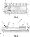
- FIG. 2 schematically shows a cross section of a possible implementation of an electrostatically triggered valve 22 in a fluidic device 20.
- fluid 6 enters a channel 21, formed between an upper substrate 5 and a middle substrate 8, by capillary force and reaches an abrupt change in the cross section of the fluidic channel 21 at the interface between middle substrate 8 and bottom substrate 1, at which point the capillary flow will stop.
- the capillary-stop valve 22 is formed by the channel 21.
- the fluid 6 will be attracted to the counter electrode 2.
- the fluid 6 contacts the counter electrode it experiences a capillary force in the fluidic channel 12 resulting in a continuation of capillary flow also when the potential difference between the electrodes is removed.
- Figure 3 shows a cross-section of a device 20 that can be used to create a flow of two liquids 6,13, which are contained in two liquid containers, each provided with a capillary-stop valve that can be triggered independently by means of mutually cooperating electrodes 2, 7.
- the second electrode 2 is formed over substantially the entire upper surface of bottom substrate 1 and is connected to the voltage source (not shown) by a connector 3.
- the second electrodes 2 are hereby formed as one integrally formed electrode.
- the first electrodes 7 are individually controllable. Instead of one integrally formed second electrode 2, the first electrodes 7 may be formed as one integrally formed electrode in which case the second electrodes 2 are formed as individual controllable electrodes.
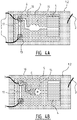
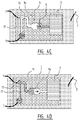
- Figures 4a-4d show a top down view of the sequence that is generated with the embodiment of the device of figure 3 .
- Liquid 6 is first triggered, figure 4a , flows through the fluidic structure, figure 4b , and is absorbed by a blotting pad 4, figure 4c .
- the second liquid 13 is triggered, which flows through the fluidic structure, figure 4d , and is absorbed by the blotting pad 4.
- the fluid flow of the liquids 6, 13 is indicated by the arrows.
- a sequence like this could for example be used to first flow a sample through a device and subsequently wash the device with the second liquid.
- the liquids 6, 13 both flow through a reaction zone 14.
- the reaction zone 14 is a zone wherein (bio)chemical species contained in the sample, for example the first liquid 6, may undergo a chemical reaction, for example for detecting or sensing said particular particles. If the second liquid 13 is a washing liquid it may wash the reaction zone 14, such that unreacted or unbound species are removed from the detection site.
- the liquid container containing the first liquid 6 is connected to reaction zone 14 via a channel 16.
- the liquid container containing second liquid 13 is connected to reaction zone 14 via a channel 17 and said channel 16, wherein channel 17 is in medium through flow connection with channel 16.
- any number of liquid containers with a capillary-stop valve and mutually cooperating electrodes for triggering the capillary-stop valves may be used.
- a device that comprises three liquid containers each containing a respective liquid 6, 13, 15.
- the liquid container containing first liquid 6 is connected to reaction zone 14 via a channel 16.
- the liquid container containing second liquid 13 is connected to reaction zone 14 via a channel 17.
- the liquid container containing third liquid 15 is connected to reaction zone 14 via a channel 18.
- all liquids 6, 13, 15 will flow successively through reaction zone 14 after triggering of the respective stop valve thereof, which stop valves can be triggered independently by means of mutually cooperating electrodes 2, 7.
- the second electrode 2 is formed over substantially the entire upper surface of bottom substrate 1 and is connected to the voltage source (not shown) by a connector 3.
- reaction zone 14 is a zone wherein first (bio)chemical species contained in the sample, for example the first liquid 6, may undergo a chemical reaction, for example for detecting or sensing said first species. If the second liquid 13 is a washing liquid it will then wash the reaction zone 14. After washing with said second liquid 13, a third liquid 15 may be triggered to flow through reaction zone 14, wherein particular second species contained in the third liquid may undergo a second chemical reaction, for example for aiding in detecting or sensing said first species.
- the embodiment of figures 6a - 6d is similar to the embodiment of figures 5 and differs there from only in that an additional stop valve 22 is provided between reaction zone 14 and blotting pad 4.
- the residence time of each liquid 6, 13, 15 in reaction zone 14 is adjustable, independent of the flow time of the liquid through the reaction zone 14.
- none of the liquid containers is triggered.
- the liquid container containing first liquid 6 is triggered.
- Liquid 6 will flow through channel 16 and reaction zone 14 up to the extra stop valve 22.
- the liquid 6 will remain in reaction zone 14 until stop valve 22 is triggered, see figure 6c .
- After triggering the extra stop valve 22 liquid 6 will flow to blotting pad 4.
- By adjusting the residence time of a liquid in reaction zone 14 more or less time for chemical reactions may be provided.
- the reader is referred to the description of figure 5 .
- Figure 7 shows a type of biochemistry assay, so called enzyme-linked immunosorbent assay (ELISA), for which the device according to the invention may be used.
- ELISA enzyme-linked immunosorbent assay
- reaction zone 14 at least one antibody 30 with specificity for a particular antigen is provided.
- the sample with an unknown amount of antigen 31 is immobilized specifically via capture by another antibody specific to the same antigen, in a "sandwich" ELISA.
- the detection antibody 32 is added, forming a complex with the antigen 31.
- the detection antibody can be covalently linked to an enzyme, or can itself be detected by a secondary antibody 33 that is linked to an enzyme through bioconjugation.
- the plate is typically washed with a mild detergent solution to remove any proteins or antibodies that are not specifically bound.
- the plate is developed by adding an enzymatic substrate to produce a visible signal, which indicates the quantity of antigen in the sample.
- the various samples with antigens 31, detection antibodies 32 and secondary antibodies 33, and the washing liquid(s) may be contained in a respective liquid container of the device. After triggering of the respective stop valve thereof a sample or a washing liquid will flow through reaction zone 14, such that the above described steps of ELISA may take place.
- ELISA may be performed as desired.
- the number of liquid containers may easily be adapted to the type of assay.
- the voltage to be applied for triggering a capillary-stop valve is dependent on several parameters. The required voltage is dependent on for example, but not limited thereto, the type of liquid 6, 13, 15, the size of the gap 24, the material and diameter of the capillary-stop valve 22.
- first and/or second liquid containers and/or stop valves with respective pair(s) of electrodes may be chosen.
- valve 22 the residence time of each liquid 6, 13, 15 in reaction zone 14 is adjustable, independent of the flow time of the liquid through the reaction zone 14.
- none of the liquid containers is triggered.
- the liquid container containing first liquid 6 is triggered.
- Liquid 6 will flow through channel 16 and reaction zone 14 up to the extra stop valve 22.
- the liquid 6 will remain in reaction zone 14 until stop valve 22 is triggered, see figure 6c .
- After triggering the extra stop valve 22 liquid 6 will flow to blotting pad 4.
- By adjusting the residence time of a liquid in reaction zone 14 more or less time for chemical reactions may be provided.
- Figure 7 shows a type of biochemistry assay, so called enzyme-linked immunosorbent assay (ELISA), for which the device according to the invention may be used.
- ELISA enzyme-linked immunosorbent assay
- reaction zone 14 at least one antibody 30 with specificity for a particular antigen is provided.
- the sample with an unknown amount of antigen 31 is immobilized specifically via capture by another antibody specific to the same antigen, in a "sandwich" ELISA.
- the detection antibody 32 is added, forming a complex with the antigen 31.
- the detection antibody can be covalently linked to an enzyme, or can itself be detected by a secondary antibody 33 that is linked to an enzyme through bioconjugation.
- the plate is typically washed with a mild detergent solution to remove any proteins or antibodies that are not specifically bound.
- the plate is developed by adding an enzymatic substrate to produce a visible signal, which indicates the quantity of antigen in the sample.
- the various samples with antigens 31, detection antibodies 32 and secondary antibodies 33, and the washing liquid(s) may be contained in a respective liquid container of the device. After triggering of the respective stop valve thereof a sample or a washing liquid will flow through reaction zone 14, such that the above described steps of ELISA may take place.
- ELISA may be performed as desired.
- the number of liquid containers may easily be adapted to the type of assay.
- the voltage to be applied for triggering a capillary-stop valve is dependent on several parameters. The required voltage is dependent on for example, but not limited thereto, the type of liquid 6, 13, 15, the size of the gap 24, the material and diameter of the capillary-stop valve 22.
- first and/or second liquid containers and/or stop valves with respective pair(s) of electrodes may be chosen.
Landscapes
- Chemical & Material Sciences (AREA)
- Engineering & Computer Science (AREA)
- General Engineering & Computer Science (AREA)
- Dispersion Chemistry (AREA)
- Health & Medical Sciences (AREA)
- Mechanical Engineering (AREA)
- Analytical Chemistry (AREA)
- General Health & Medical Sciences (AREA)
- Hematology (AREA)
- Clinical Laboratory Science (AREA)
- Chemical Kinetics & Catalysis (AREA)
- Physical Or Chemical Processes And Apparatus (AREA)
Description
- The invention relates to a device, comprising:
- a plurality of first liquid containers, each for containing a liquid,
- a plurality of capillary-stop valves, each being in medium through flow connection with a respective first liquid container for stopping said liquid in said container from flowing out of said container via said capillary-stop valve;
- at least one second liquid container for receiving said liquid(s);
- a plurality of first electrodes being arranged such that in use each said first electrode is in contact with said liquid in a respective first liquid container, and
- a plurality of second electrodes, each being spaced apart from a respective capillary-stop valve by an electrically insulating medium gap, and
- a voltage source or a plurality of voltage sources connected to said each pair of first and second electrodes which is activatable for applying an electric potential difference at each pair of first and second electrodes such that the liquid in the first liquid container is attracted in the direction of said second electrode so as to allow the liquid to overcome the stopping effect of the capillary-stop valve for discharging liquid from said first liquid container via said capillary-stop valve. Such a device is known perse and is a micro fluidic device in which the flow of the liquid contained in the container can be controlled by said capillary-stop valves.
- It is noted that in this respect the capillary-stop valve refers to both a capillary valve and a hydrophobic valve, which are both well-established valve types that have no moving parts and are easily implemented in the production of a micro-fluidic devices. Such capillary-stop valves function by introducing an abrupt increase in the effective contact angle between the liquid and the inner surface of the capillary-stop valve, e.g. by means of change of geometry of the capillary valve or a change of the wettability of the inner surface of the hydrophobic valve. A capillary-stop valve may for example comprise a sudden increase of diameter with a close to 90 degrees transition from a small to larger diameter or it may comprise a substantially hydrophobic section or a combination of the two.
- A microfluidic device is for instance known from
US 6,444,106 B1 which device has a layer that has a capillary break formed by a capillary sluice. The capillary sluice has a lower surface and an upper surface. An input channel is coupled to the capillary break. A first electrode is disposed proximate the lower surface. The first electrode is coupled to the voltage source. A second electrode is spaced a first predetermined distance from the first electrode coupled to the voltage source. A third electrode is spaced apart from the second electrode and positioned within the input channel from the first electrode coupled to the voltage source. - In
US2003/049177 A1 an apparatus and device for dispensing femtoliter to nanoliter volumes of liquid samples are disclosed. The apparatus includes a liquid-support plate, two electrodes, a substrate, and a control unit. The liquid support plate has a plurality of liquid-support regions, each capable of supporting a liquid meniscus thereon. The first electrode contains a plurality of electrode connections, each operatively connected to one of the liquid support regions, for electrical contact with a meniscus supported in such region. The substrate has a first side confronting the plate and an opposite side, and a plurality of sample-holding regions formed in the first side. The second electrode is disposed adjacent one of the two substrate sides. Thus, a selected volume of the liquid can be ejected from or to one or more of the liquid-support regions to or from one or more of the sample-holding regions. - It is an object of the invention to improve the device according to the preamble.
- This objective is achieved by a device of the type according to the preamble, that is characterized by:
at least two of said plurality of first liquid containers are in medium through flow connection with a same second liquid container,
wherein said same second liquid container of the at least one second liquid containers is an absorber. - In particular an absorber, such as a blotting pad or the like, has the advantage that such an absorber will suck up the liquid that is discharged from said liquid container via said capillary-stop valve. As a result of said suction force all the liquid discharged from said liquid container is drawn to the absorber, such that no liquid will remain in the first liquid container or in a flow path between the first and second liquid containers.
- It is noted that in particular when an absorber is used, it is not necessary to provide a gas to clear the flow path between the first and second liquid containers.
- By attracting the liquid in the direction of said second electrode as a result of the electrostatic force the liquid is drawn out of the liquid container due to any of the following two effects or a combination thereof.
- The first effect is that by attracting the liquid in the direction of the second electrode the contact angle of the liquid with respect to an opening of the capillary-stop valve is increased. After reaching a predetermined minimum contact angle the liquid will overcome the stopping effect provided by the capillary-stop valve and will flow out the fluid container. Said predetermined minimum contact angle is dependent on the material of the substrate and/or the type of liquid.
- The second effect is that by attracting the liquid in the direction of the second electrode the liquid will come into contact with the second electrode or with a wall of a second fluid container, wherein after making contact with the second electrode or said wall the liquid will be discharged from said liquid container.
- The second electrode is arranged such that in most cases a gas gap, in particular an air gap, is present between the second electrode and the liquid. In particular, the second electrode is arranged such that the second electrode does not overlap with the edge of the liquid meniscus, see also the figures. It is noted that instead of a gas said electrically insulating medium may be any immiscible fluidic medium, for example oil.
- The mutually cooperating first electrode and second electrode also offer the advantage, that they may be used for detecting whether the capillary-stop valve has been activated or triggered, either intentionally or unintentionally, by measuring the electrical current as a function of the applied voltage or AC frequency. In the untriggered state a DC current cannot flow whereas when the valve has been triggered and the liquid is electrically conductive a DC current can flow. Alternatively, when using an AC voltage the electrical impedance of the system is affected whether the valve has been triggered or not. The advantage of an AC voltage is that an electrochemical reaction at the electrodes is not needed in order to measure a current, and therefore there is no risk of changing the chemical composition of the liquid.
- The triggering of the capillary-stop valve according the invention can advantageously be applied to micro fluidic devices already comprising a voltage source for a different purpose.
- Said liquid container is for example, but not limited thereto, a channel, in particularly a capillary channel, a reservoir, or a well of a microtiterplate volume.
- According to the invention said device comprises at least one second liquid container for receiving liquid that is discharged from said liquid container via said capillary-stop valve.
- A second liquid container is for example, but not limited thereto, a channel, in particularly a capillary channel, a reservoir, or an absorber.
- In particular an absorber, such as a blotting pad or the like, has the advantage that such an absorber will suck up the liquid that is discharged from said liquid container via said capillary-stop valve. As a result of said suction force all the liquid discharged from said liquid container is drawn to the absorber, such that no liquid will remain in the first liquid container or in a flow path between the first and second liquid containers.
- It is noted that in particular when an absorber is used, it is not necessary to provide a gas to clear the flow path between the first and second liquid containers.
- Said reservoir may for example be a reaction zone, in which reaction zone chemical reactions between (bio)chemical species in said liquid and other species , for example antibodies contained in said reaction zone, may take place, for example for detecting or sensing analytes in the liquid or sample.
- A plurality of second liquid containers may be provided. For example, said stop valve may be provided between said first liquid container and a (capillary) channel, wherein said (capillary) channel may connect to said reaction zone and/or said absorber.
- In another embodiment of the device according to the invention, the capillary-stop valve and the second liquid container are arranged such that the flow direction of the liquid in the capillary-stop valve is substantially orthogonal to the flow direction of the liquid in the second liquid container.
- In even another embodiment of the device according to the invention, the device comprises a first substrate comprising said liquid container and a second substrate comprising said second liquid container.
- Such a device has the advantage that the freedom of manufacturing is increased. For example, said first substrate and said second substrate may be made independent from each other, if preferred in different locations, and then assembled. Also, this allows said first substrate and said second substrate to be made from different materials.
- In yet even another embodiment of the device according to the invention, the second substrate is made of an electrically conductive material for forming said second electrode.
- Alternatively, said second substrate is made of an electrically insulating material comprising a patterned or unpatterned electrically conductive layer for forming said second electrode.
- Said electrically conductive layer may for example be applied on a side of the insulating material that is facing towards said first electrode.
- Alternatively, said electrically conductive layer is arranged on a side of the insulating material that is facing away from said first electrode.
- Such an arrangement offers the advantage that the liquid will not come into direct contact with the second electrode after discharging from the liquid container.
- Said device or said first substrate is for example, but not limited thereto, made of glass, silicon, ceramic or polymer.
- The plurality of (first) liquid containers, each comprising a capillary-stop valve and mutually cooperating first and second electrodes offer the advantage, that the discharge of liquid from each liquid container may be controlled by a user. The activation or triggering of each capillary-stop valve may take place at substantially the same time, or may take place sequentially, or any combination thereof, which allows for good controlling of the liquid flow in the device. The activation or triggering of the plurality of capillary-stop valves may optionally be programmed in a computer program, which computer program may be included in the device.
- With the device according to the invention wherein at least two of said plurality of first liquid containers are in medium through flow connection with said at least one second liquid container it is possible to have different liquids flow in, to or through the same second liquid container, such as a (capillary) channel, a reservoir, for example a reaction zone, or an absorber. Such an embodiment is for example suitable for use as a biochemistry assay, in which a sample may flow through a reaction zone after triggering the stop valve of the liquid container in which said sample is contained, and wherein next a washing liquid may flow through said same reaction zone after triggering the stop valve of the liquid container in which said washing liquid is contained. This washing step can for instance be applied to remove any non-reacted or non-bound species.
- Said first liquid containers may connect to said second liquid container via separate channels or other separate connection means. Alternatively, said first liquid containers may be in medium through flow connection with each other, wherein for example a channel or other connection means connect at least two first liquid containers, and wherein one of the first liquid containers connects to said second liquid container. In such an arrangement the other first liquid containers connect to said second liquid container via said one first liquid container.
- In yet even another embodiment of the device according to the invention, said device comprises:
- a second capillary-stop valve that is in medium through flow connection with said second liquid container for stopping said liquid in said second liquid container from flowing out of said second liquid container via said second capillary-stop valve;
- a second first electrode being arranged such that in use said second first electrode is in contact with said liquid in a said second liquid container, and
- a second second electrode that is spaced apart from said second capillary-stop valve by an electrically insulating medium gap,
- Such a second capillary-stop valve that may be triggered independently from the first capillary-stop valve has the advantage that the residence time of the liquid in the second reservoir is adjustable by adjusting the time period between triggering the first capillary-stop valve and the second capillary-stop valve. This is for example advantageous if the second liquid container comprises a reaction zone. Said second liquid container may be in medium through flow connection with a further second liquid container, which may also be referred to as a third liquid container, for receiving the liquid from the second liquid container. The further second liquid container or third liquid container may for example comprise an absorber.
- For triggering the plurality of capillary-stop valves, in particular for example the first and second capillary-stop valves, sequentially, the electric potential difference can be applied to one pair of first and second electrodes or pair of second first and second electrodes independently of the other pair(s).
- For example, a plurality of switches may be provided, each switch breaking an electrical circuit of the respective pair of first and second electrodes or pair of second first and second electrodes, wherein the capillary-stop valve may be activated or triggered by operating said switch for completing the respective electrical circuit.
- One electrode of a pair of first and second electrodes or a pair of second first and second electrodes may be integrally formed with another electrode of another pair of first and second electrodes or another pair of second first and second electrodes.
- For example, all or part of said plurality of first electrodes may be integrally formed while all or part of said plurality of second electrodes of those pairs are not integrally formed and are therefore individually controllable, such that a potential difference can be applied at each pair of first and second electrodes individually, even when the first electrodes are formed as one integral electrode. Alternatively, all or part of said plurality of second electrodes may be integrally formed while all or part of said plurality of first electrodes of those pairs are not integrally formed and are therefore individually controllable. Thus, a plurality of electrodes does not necessarily have to be a plurality of separate electrodes but may be formed as one integral electrode. A plurality of electrodes is in that case to be understood as an integrally formed electrode fulfilling the functions of a plurality of electrodes.
- For example, the second electrode may be integrally formed with the second first electrode while the first electrode and the second second electrode are not integrally formed and are therefore individually controllable. Such a configuration is possible if, when the liquid is stopped at the second stop valve, the liquid is still in contact with the second electrode at the first stop valve, such that the second electrode of the first stop valve may function as the second first electrode of the second stop valve.
- For example, the second first electrode may be integrally formed with the first electrode(s) while the second second electrode is not integrally formed with the second electrode(s) and are therefore individually controllable. Alternatively the second second electrode may be integrally formed with the second electrode(s) while the second first electrode is not integrally formed with the first electrode(s) and are therefore individually controllable.
- The invention is not limited to the above described examples of integrally formed electrodes. It will be clear for the skilled person which electrodes may be formed integrally or not.
- The integrally formed electrodes may for example be formed by an electrically conductive substrate or an electrically conductive layer provided on said substrate.
- The invention also relates to a method for activating a capillary-stop valve of a device, said method comprising the step of:
- (a) applying an electric potential difference at two mutually cooperating electrodes, wherein a first electrode is in contact with a liquid that is stopped by said capillary-stop valve, and wherein the second electrode is spaced apart from said capillary-stop valve, such that the liquid is attracted in the direction of said second electrode so as to allow the liquid to overcome the stopping effect of the capillary-stop valve, and comprising the step, to be performed before step (a), of:
- (b) providing a device according to the invention as described above,
- As described above, said attraction occurs as a result of the electrostatic force, as a result of which the liquid will overcome the stopping effect of the capillary-stop valve.
- In another embodiment of the method according to the invention said device further comprises the step of:
- (c) repeating step (a) for each pair of first and second electrodes independent of the other pair(s).
- In yet another embodiment of the method according to the invention said substrate further comprises the step of:
- (c) repeating step (a) for each pair of second first and second electrodes independent of the other pair(s).
- As described above, such methods allow for controlling the triggering of the plurality of capillary-stop valves, either simultaneously, sequentially, or any combination thereof. In addition, such methods allow for, for example, a biochemistry assay to be performed.
- The invention will now be explained in more detail with reference to figures illustrated in a drawing, wherein:
-
figures 1a, 1b are a schematic cross section of a first and second embodiment of the device according to the invention; -
figure 2 is a schematic cross section of a third embodiment of the device according to the invention; -
figure 3 is a schematic cross section of a fourth embodiment of the device according to the invention; -
figures 4a-4d show the steps of activating the fluid flow of the device offigure 3 ; -
figure 5 is a schematic top view of a fifth embodiment of the device according to the invention; -
figures 6a-6d show the steps of activating the fluid flow of sixth embodiment of the device according to the invention; and -
figure 7 shows the steps of a type of biochemistry assay for which the device according to the invention may be used. Same elements are denoted by the same reference numerals. -
Figure 1a shows adevice 20, comprising aliquid container 21 for containing aliquid 6 and a capillary-stop valve 22 that is in medium through flow connection with saidliquid container 21 for stopping saidliquid 6 in saidcontainer 21 from flowing out of saidcontainer 21 via said capillary-stop valve 22. Afirst electrode 7 is arranged in theliquid container 21. It is noted that thefirst electrode 7 may be located anywhere, as long as it contacts saidliquid 6 in saidliquid container 21. Theliquid container 21 of the first embodiment of thedevice 20 is formed by the upper side of thedevice 20, on which theliquid 6 is applied. The capillary-stop valve 22 is formed by an opening in thedevice 20, said opening extending from the upper side of thedevice 20 to a secondliquid container 12, wherein said opening has a sudden increase of diameter with a close to 90 degrees transition from a small to larger diameter, such that said opening functions as the capillary-stop valve 22. A second orcounter electrode 2 arranged on a side of the secondliquid container 12 facing said capillary-stop valve 22 and is spaced apart from said capillary-stop valve 22 by an electrically insulatingmedium gap 24. A voltage source (V) is connected to saidfirst electrode 7 and saidsecond electrode 2, which voltage source (V) is activatable by means of aswitch 25 for applying an electric potential difference at the first and second electrode such that the liquid 6 in theliquid container 21 is attracted in the direction of saidsecond electrode 2 so as to allow the liquid 6 to overcome the stopping effect of the capillary-stop valve 22 for discharging liquid 6 from saidliquid container 21 via said capillary-stop valve 22. Said liquid 6 is attracted in the direction of saidsecond electrode 2 as a result of the electrostatic force, indicated by FEL. A contact angle α between the liquid and the opening of the capillary-stop valve 22 is thereby increased. Once the contact angle α reaches a predetermined minimum contact angle theliquid 6 will overcome the stopping effect provided by the capillary-stop valve 22 and will flow out thefluid container 21. Additionally, or alternatively, said liquid may come into contact with a wall of the secondliquid container 12 or with thesecond electrode 2. At this point the capillary force is present again resulting in a continuation of flow of the liquid 6 into thesecond container 12 without the necessity of applying any further external force. Said capillary-stop valve 22 is arranged in anupper part 10 of thedevice 20, and the secondliquid container 12 is arranged in alower part 11 of thedevice 20. Saidupper part 10 and saidlower part 11 may be formed as one integral substrate, or may be formed as two separated substrates, which are connected to each other. Said secondliquid container 12 is in this embodiment a capillary channel formed in thelower part 11 or a capillary split formed between theupper part 10 and thelower part 11. Due to the capillary effect saidliquid 6 is transported in thesecond container 12 after triggering the capillary-stop valve 22. As suchfigure 1a shows the principle of electrostatically triggering afluid 6 stopped in a capillary-stop valve 22 and acounter electrode 2 opposite of theliquid 6. - It is noted that the
meniscus 23 of theliquid 6 is shown in an attracted state, just before theliquid 6 overcomes the stopping effect of the capillary-stop valve 22. Before closing theswitch 25 said meniscus has a more or less flat shape. - It is further noted that it is clear from
figure 1a that the capillary-stop valve 22 and the secondliquid container 12 are arranged such that the flow direction of the liquid 6 in the capillary-stop valve 22 is substantially orthogonal to the flow direction of the liquid 6 in the secondliquid container 12. - The embodiment of
figure 1b differs from the embodiment offigure 1a in that thesecond electrode 2 is arranged on a side oflower part 11 that is facing away from saidfirst electrode 7. In this embodiment saidlower part 11 is a dielectric substrate. As suchfigure 1b shows the principle of electrostatically triggering afluid 6 stopped in a capillary-stop valve 22 and acounter electrode 2 at the bottom of adielectric substrate 11. -
Figure 2 schematically shows a cross section of a possible implementation of an electrostatically triggeredvalve 22 in afluidic device 20. Here,fluid 6 enters achannel 21, formed between anupper substrate 5 and amiddle substrate 8, by capillary force and reaches an abrupt change in the cross section of thefluidic channel 21 at the interface betweenmiddle substrate 8 andbottom substrate 1, at which point the capillary flow will stop. Thus the capillary-stop valve 22 is formed by thechannel 21. By applying a potential difference betweenelectrode 7 andcounter electrode 2 thefluid 6 will be attracted to thecounter electrode 2. When the fluid 6 contacts the counter electrode it experiences a capillary force in thefluidic channel 12 resulting in a continuation of capillary flow also when the potential difference between the electrodes is removed. -
Figure 3 shows a cross-section of adevice 20 that can be used to create a flow of twoliquids electrodes second electrode 2 is formed over substantially the entire upper surface ofbottom substrate 1 and is connected to the voltage source (not shown) by aconnector 3. Thesecond electrodes 2 are hereby formed as one integrally formed electrode. Thefirst electrodes 7 are individually controllable. Instead of one integrally formedsecond electrode 2, thefirst electrodes 7 may be formed as one integrally formed electrode in which case thesecond electrodes 2 are formed as individual controllable electrodes. -
Figures 4a-4d show a top down view of the sequence that is generated with the embodiment of the device offigure 3 .Liquid 6 is first triggered,figure 4a , flows through the fluidic structure,figure 4b , and is absorbed by ablotting pad 4,figure 4c . Next, thesecond liquid 13 is triggered, which flows through the fluidic structure,figure 4d , and is absorbed by theblotting pad 4. The fluid flow of theliquids liquids reaction zone 14. Thereaction zone 14 is a zone wherein (bio)chemical species contained in the sample, for example thefirst liquid 6, may undergo a chemical reaction, for example for detecting or sensing said particular particles. If thesecond liquid 13 is a washing liquid it may wash thereaction zone 14, such that unreacted or unbound species are removed from the detection site. The liquid container containing thefirst liquid 6 is connected toreaction zone 14 via achannel 16. The liquid container containing second liquid 13 is connected toreaction zone 14 via achannel 17 and saidchannel 16, whereinchannel 17 is in medium through flow connection withchannel 16. - It is noted that instead of one or two liquid containers, each with a capillary-stop valve and mutually cooperating electrodes for triggering the capillary-stop valves, any number of liquid containers with a capillary-stop valve and mutually cooperating electrodes for triggering the capillary-stop valves may be used.
- For example in
figure 5 a device is shown that comprises three liquid containers each containing arespective liquid first liquid 6 is connected toreaction zone 14 via achannel 16. The liquid container containing second liquid 13 is connected toreaction zone 14 via achannel 17. The liquid container containing third liquid 15 is connected toreaction zone 14 via achannel 18. In this embodiment, allliquids reaction zone 14 after triggering of the respective stop valve thereof, which stop valves can be triggered independently by means of mutually cooperatingelectrodes second electrode 2 is formed over substantially the entire upper surface ofbottom substrate 1 and is connected to the voltage source (not shown) by aconnector 3. As for the embodiment offigures 3 and4a - 4d , a sequence like this could for example be used to first flow a sample through a device and subsequently wash the device with the second liquid, and then flow a third liquid through the device. Thereaction zone 14 is a zone wherein first (bio)chemical species contained in the sample, for example thefirst liquid 6, may undergo a chemical reaction, for example for detecting or sensing said first species. If thesecond liquid 13 is a washing liquid it will then wash thereaction zone 14. After washing with saidsecond liquid 13, a third liquid 15 may be triggered to flow throughreaction zone 14, wherein particular second species contained in the third liquid may undergo a second chemical reaction, for example for aiding in detecting or sensing said first species. The difference between the embodiment offigures 3 and4a - 4d and the embodiment offigure 5 is that thechannels 16, 17 (and 18) in the embodiment offigure 5 are each connected separately from the other channels toreaction zone 14. As such, only one liquid of the threeliquids respective channel liquids reaction zone 14. - The embodiment of
figures 6a - 6d is similar to the embodiment offigures 5 and differs there from only in that anadditional stop valve 22 is provided betweenreaction zone 14 andblotting pad 4. By providing theextra stop valve 22 the residence time of each liquid 6, 13, 15 inreaction zone 14 is adjustable, independent of the flow time of the liquid through thereaction zone 14. Infigure 6a none of the liquid containers is triggered. Infigure 6b the liquid container containingfirst liquid 6 is triggered. Liquid 6 will flow throughchannel 16 andreaction zone 14 up to theextra stop valve 22. Theliquid 6 will remain inreaction zone 14 untilstop valve 22 is triggered, seefigure 6c . After triggering theextra stop valve 22 liquid 6 will flow toblotting pad 4. By adjusting the residence time of a liquid inreaction zone 14 more or less time for chemical reactions may be provided. For a further description of the embodiment offigures 6a - 6d the reader is referred to the description offigure 5 . -
Figure 7 shows a type of biochemistry assay, so called enzyme-linked immunosorbent assay (ELISA), for which the device according to the invention may be used. Inreaction zone 14 at least oneantibody 30 with specificity for a particular antigen is provided. The sample with an unknown amount ofantigen 31 is immobilized specifically via capture by another antibody specific to the same antigen, in a "sandwich" ELISA. After theantigen 31 is immobilized, thedetection antibody 32 is added, forming a complex with theantigen 31. The detection antibody can be covalently linked to an enzyme, or can itself be detected by asecondary antibody 33 that is linked to an enzyme through bioconjugation. Between each step, the plate is typically washed with a mild detergent solution to remove any proteins or antibodies that are not specifically bound. After the final wash step, the plate is developed by adding an enzymatic substrate to produce a visible signal, which indicates the quantity of antigen in the sample. The various samples withantigens 31,detection antibodies 32 andsecondary antibodies 33, and the washing liquid(s) may be contained in a respective liquid container of the device. After triggering of the respective stop valve thereof a sample or a washing liquid will flow throughreaction zone 14, such that the above described steps of ELISA may take place. By triggering the stop valves of the liquid containers consecutively in the desired order, at desired moments, and optionally with desired residence time in the reaction zone, ELISA may be performed as desired. The number of liquid containers may easily be adapted to the type of assay. The voltage to be applied for triggering a capillary-stop valve is dependent on several parameters. The required voltage is dependent on for example, but not limited thereto, the type ofliquid gap 24, the material and diameter of the capillary-stop valve 22. - It is noted that the figures explain the invention with respect to a capillary valve. It is clear for the skilled person that the invention also applies to a hydrophobic valve, which both type of valves are defined by the term capillary-stop valve.
- It is further noted that the invention is not limited to the above discussed exemplary embodiments but also extends to other variants within the scope of the appended claims.
- For example, the skilled person will appreciate that each desired configuration and/or number of first and/or second liquid containers and/or stop valves with respective pair(s) of electrodes may be chosen.
-
valve 22 the residence time of each liquid 6, 13, 15 inreaction zone 14 is adjustable, independent of the flow time of the liquid through thereaction zone 14. Infigure 6a none of the liquid containers is triggered. Infigure 6b the liquid container containingfirst liquid 6 is triggered. Liquid 6 will flow throughchannel 16 andreaction zone 14 up to theextra stop valve 22. Theliquid 6 will remain inreaction zone 14 untilstop valve 22 is triggered, seefigure 6c . After triggering theextra stop valve 22 liquid 6 will flow toblotting pad 4. By adjusting the residence time of a liquid inreaction zone 14 more or less time for chemical reactions may be provided. For a further description of the embodiment offigures 6a - 6d the reader is referred to the description offigure 5 . -
Figure 7 shows a type of biochemistry assay, so called enzyme-linked immunosorbent assay (ELISA), for which the device according to the invention may be used. Inreaction zone 14 at least oneantibody 30 with specificity for a particular antigen is provided. The sample with an unknown amount ofantigen 31 is immobilized specifically via capture by another antibody specific to the same antigen, in a "sandwich" ELISA. After theantigen 31 is immobilized, thedetection antibody 32 is added, forming a complex with theantigen 31. The detection antibody can be covalently linked to an enzyme, or can itself be detected by asecondary antibody 33 that is linked to an enzyme through bioconjugation. Between each step, the plate is typically washed with a mild detergent solution to remove any proteins or antibodies that are not specifically bound. After the final wash step, the plate is developed by adding an enzymatic substrate to produce a visible signal, which indicates the quantity of antigen in the sample. The various samples withantigens 31,detection antibodies 32 andsecondary antibodies 33, and the washing liquid(s) may be contained in a respective liquid container of the device. After triggering of the respective stop valve thereof a sample or a washing liquid will flow throughreaction zone 14, such that the above described steps of ELISA may take place. By triggering the stop valves of the liquid containers consecutively in the desired order, at desired moments, and optionally with desired residence time in the reaction zone, ELISA may be performed as desired. The number of liquid containers may easily be adapted to the type of assay. The voltage to be applied for triggering a capillary-stop valve is dependent on several parameters. The required voltage is dependent on for example, but not limited thereto, the type ofliquid gap 24, the material and diameter of the capillary-stop valve 22. - It is noted that the figures explain the invention with respect to a capillary valve. It is clear for the skilled person that the invention also applies to a hydrophobic valve, which both type of valves are defined by the term capillary-stop valve.
- It is further noted that the invention is not limited to the above discussed exemplary embodiments but also extends to other variants within the scope of the appended claims.
- For example, the skilled person will appreciate that each desired configuration and/or number of first and/or second liquid containers and/or stop valves with respective pair(s) of electrodes may be chosen.
Claims (13)
- Device (20), comprising:- a plurality of first liquid containers, each for containing a liquid (6, 13, 15),- a plurality of capillary-stop valves (22), each being in medium through flow connection with a respective first liquid container for stopping said liquid (6, 13, 15) in said container from flowing out of said container via said capillary-stop valve (22);- at least one second liquid container for receiving said liquid(s) (6, 13, 15);- a plurality of first electrodes (7) being arranged such that in use each said first electrode (7) is in contact with said liquid (6, 13, 15) in a respective first liquid container, and- a plurality of second electrodes (2), each being spaced apart from a respective capillary-stop valve (22) by an electrically insulating medium gap (24), and- a voltage source or a plurality of voltage sources (V) connected to said each pair of first and second electrodes (7, 2) which is activatable for applying an electric potential difference at each pair of first and second electrodes (7, 2) such that the liquid (6, 13, 15) in the first liquid container is attracted in the direction of said second electrode (2) so as to allow the liquid (6, 13, 15) to overcome the stopping effect of the capillary-stop valve (22) for discharging liquid (6, 13, 15) from said first liquid container via said capillary-stop valve (22),characterized in that
at least two of said plurality of first liquid containers are in medium through flow connection with a same second liquid container,
wherein said same second liquid container of the at least one second liquid containers is an absorber (4). - Device (20) according to claim 1, wherein a said first liquid container is a channel (21), in particularly a capillary channel (21), a reservoir, or a well of a microtiterplate volume.
- Device (20) according to claim 1 or 2, wherein a said second liquid container is a channel (16, 17, 18), in particularly a capillary channel (16, 17, 18), a reservoir, or an absorber (4).
- Device (20) according to any of the preceding claims, wherein a said capillary-stop valve (22) and a said second liquid container are arranged such that the flow direction of the liquid (6, 13, 15) in the capillary-stop valve (22) is orthogonal to the flow direction of the liquid (6, 13, 15) in the second liquid container.
- Device (20) according to any of the preceding claims, wherein the device (20) comprises a first substrate comprising a said first liquid container and a second substrate comprising a said second liquid container.
- Device (20) according to claim 5, wherein the second substrate is made of an electrically conductive material for forming said second electrode (2).
- Device (20) according to claim 5, wherein said second substrate is made of an electrically insulating material comprising a patterned or unpatterned electrically conductive layer for forming said second electrode (2).
- Device (20) according to claim 7, wherein said electrically conductive layer is arranged on a side of the insulating material that is facing towards or away from said first electrode (7).
- Device (20) according to any of the preceding claims, comprising:- a second capillary-stop valve (22) that is in medium through flow connection with a said second liquid container for stopping said liquid in said second liquid container from flowing out of said second liquid container via said second capillary-stop valve (22);- a second first electrode (7) being arranged such that in use said second first electrode (7) is in contact with said liquid (6, 13, 15) in a said second liquid container, and- a second second electrode (2) that is spaced apart from said second capillary-stop valve (22) by an electrically insulating medium gap (24),wherein said voltage source or a plurality of voltage sources (V) is connected to said pair of second first and second electrodes (7, 2) which is activatable such that an electric potential difference can be applied at said pair of second first and second electrodes (7, 2).
- Device (20) according to any of the preceding claims, wherein the electric potential difference can be applied to one pair of first and second electrodes (7, 2) or pair of second first and second electrodes (7, 2) independently of the other pair(s) (7, 2).
- Device (20) according to any of the preceding claims, wherein one electrode (7, 2) of a pair of first and second electrodes (7, 2) or a pair of second first and second electrodes (7, 2) is integrally formed with another electrode (7, 2) of another pair of first and second electrodes (7, 2) or another pair of second first and second electrodes (7, 2).
- Method for activating a capillary-stop valve (22) of a device (20), said method comprising the step of:(a) applying an electric potential difference at two mutually cooperating electrodes (7, 2), wherein a first electrode (7) is in contact with a liquid (6, 13, 15) that is stopped by said capillary-stop valve (22), and wherein the second electrode (2) is spaced apart from said capillary-stop valve (22), such that the liquid (6, 13, 15) is attracted in the direction of said second electrode (2) so as to allow the liquid (6, 13, 15) to overcome the stopping effect of the capillary-stop valve (22), and comprising the step, to be performed before step (a), of:(b) providing a device (20) according to any of the claims 1 - 11,wherein step (a) is performed by applying the electric potential difference at each pair of the first and second electrodes (7, 2).
- Method according to claim 12, wherein in step (b) the device (20) according to claim 10 or claims 10 and 11 is provided, and wherein step (a) is performed for each pair of first and second electrodes (7, 2) or pair of second first and second electrodes (7, 2) independent of the other pair(s).
Applications Claiming Priority (2)
| Application Number | Priority Date | Filing Date | Title |
|---|---|---|---|
| NL2009517A NL2009517C2 (en) | 2012-09-25 | 2012-09-25 | Device and method for activating a capillary-stop valve of a device. |
| PCT/NL2013/050687 WO2014051427A1 (en) | 2012-09-25 | 2013-09-25 | Device and method for activating a capillary-stop valve of a device |
Publications (2)
| Publication Number | Publication Date |
|---|---|
| EP2900377A1 EP2900377A1 (en) | 2015-08-05 |
| EP2900377B1 true EP2900377B1 (en) | 2019-01-02 |
Family
ID=48998667
Family Applications (1)
| Application Number | Title | Priority Date | Filing Date |
|---|---|---|---|
| EP13771235.2A Active EP2900377B1 (en) | 2012-09-25 | 2013-09-25 | Device and method for activating a capillary-stop valve of a device |
Country Status (4)
| Country | Link |
|---|---|
| US (1) | US10493454B2 (en) |
| EP (1) | EP2900377B1 (en) |
| NL (1) | NL2009517C2 (en) |
| WO (1) | WO2014051427A1 (en) |
Families Citing this family (6)
| Publication number | Priority date | Publication date | Assignee | Title |
|---|---|---|---|---|
| JP6868036B2 (en) | 2016-04-14 | 2021-05-12 | ヒューレット−パッカード デベロップメント カンパニー エル.ピー.Hewlett‐Packard Development Company, L.P. | Microfluidic device with capillary chamber |
| US10472144B2 (en) * | 2016-11-03 | 2019-11-12 | Newlight Capital, Llc | Closure device |
| US11331669B2 (en) | 2017-02-15 | 2022-05-17 | Hewlett-Packard Development Company, L.P. | Microfluidic network |
| US11441701B2 (en) | 2017-07-14 | 2022-09-13 | Hewlett-Packard Development Company, L.P. | Microfluidic valve |
| EP3569312B1 (en) * | 2018-05-15 | 2021-03-31 | IMEC vzw | A microfluidic device for electrically activated passive capillary stop valve |
| GB202001028D0 (en) * | 2020-01-24 | 2020-03-11 | Beacon Group Int Products Ltd | Fall arrest indicator |
Citations (1)
| Publication number | Priority date | Publication date | Assignee | Title |
|---|---|---|---|---|
| WO2012098140A1 (en) * | 2011-01-21 | 2012-07-26 | Fluimedix Aps | Method of controlling a flow |
Family Cites Families (5)
| Publication number | Priority date | Publication date | Assignee | Title |
|---|---|---|---|---|
| DE3645017C2 (en) | 1985-09-06 | 1990-07-12 | Fuji Electric Co., Ltd., Kawasaki, Kanagawa, Jp | |
| US5770029A (en) * | 1996-07-30 | 1998-06-23 | Soane Biosciences | Integrated electrophoretic microdevices |
| US6444106B1 (en) * | 1999-07-09 | 2002-09-03 | Orchid Biosciences, Inc. | Method of moving fluid in a microfluidic device |
| US6444173B1 (en) * | 1999-07-09 | 2002-09-03 | Orchid Biosciences, Inc. | Method of moving and detecting fluid in a microfluidic device |
| US6995024B2 (en) * | 2001-08-27 | 2006-02-07 | Sri International | Method and apparatus for electrostatic dispensing of microdroplets |
-
2012
- 2012-09-25 NL NL2009517A patent/NL2009517C2/en not_active IP Right Cessation
-
2013
- 2013-09-25 US US14/431,161 patent/US10493454B2/en active Active
- 2013-09-25 EP EP13771235.2A patent/EP2900377B1/en active Active
- 2013-09-25 WO PCT/NL2013/050687 patent/WO2014051427A1/en not_active Ceased
Patent Citations (1)
| Publication number | Priority date | Publication date | Assignee | Title |
|---|---|---|---|---|
| WO2012098140A1 (en) * | 2011-01-21 | 2012-07-26 | Fluimedix Aps | Method of controlling a flow |
Also Published As
| Publication number | Publication date |
|---|---|
| US10493454B2 (en) | 2019-12-03 |
| US20150238961A1 (en) | 2015-08-27 |
| NL2009517C2 (en) | 2014-03-27 |
| WO2014051427A1 (en) | 2014-04-03 |
| EP2900377A1 (en) | 2015-08-05 |
Similar Documents
| Publication | Publication Date | Title |
|---|---|---|
| US10493454B2 (en) | Device and method for activating a capillary-stop valve of a device | |
| KR101471054B1 (en) | Electrowetting based digital microfluidics | |
| US20130293246A1 (en) | Capacitance Detection in a Droplet Actuator | |
| US20100181195A1 (en) | Microfluidic chip for and a method of handling fluidic droplets | |
| US10183292B2 (en) | Capacitance detection in a droplet actuator | |
| US9011662B2 (en) | Droplet actuator assemblies and methods of making same | |
| US11697117B2 (en) | Methods and devices for sample analysis | |
| US9227189B2 (en) | Microfluidic liquid stream configuration system | |
| US20130018611A1 (en) | Systems and Methods of Measuring Gap Height | |
| EP3167254B1 (en) | Low sample volume sensing device | |
| CN103707643A (en) | Droplet actuator configurations and methods of conducting droplet operations | |
| US20200319135A1 (en) | Microfluidic chip and manufacturing method thereof and integrated microfluidic chip system | |
| KR100597870B1 (en) | Microfluidic chip for high speed screening or high speed analysis | |
| WO2023039678A1 (en) | Digital microfluidics (dmf) system, instrument, and cartridge including multi-sided dmf dispensing and method | |
| JP7604499B2 (en) | Action of magnetic beads on microfluidics | |
| US20090253215A1 (en) | Method for controlling the flow of liquids containing biological material by inducing electro- or magneto-rheological effect | |
| JP5363528B2 (en) | Microvalve structure and polymer-on-chip module including polymer driver | |
| US20130112559A1 (en) | Device and method for handling drops | |
| EP3161485B1 (en) | Biosensor for the detection of target components in a sample | |
| US11110455B2 (en) | Microfluidic device for electrically activated passive capillary stop valve | |
| EP3976254A1 (en) | Devices and methods for fluid actuation | |
| JP2005300213A (en) | Microfluidic processing system |
Legal Events
| Date | Code | Title | Description |
|---|---|---|---|
| PUAI | Public reference made under article 153(3) epc to a published international application that has entered the european phase |
Free format text: ORIGINAL CODE: 0009012 |
|
| 17P | Request for examination filed |
Effective date: 20150422 |
|
| AK | Designated contracting states |
Kind code of ref document: A1 Designated state(s): AL AT BE BG CH CY CZ DE DK EE ES FI FR GB GR HR HU IE IS IT LI LT LU LV MC MK MT NL NO PL PT RO RS SE SI SK SM TR |
|
| AX | Request for extension of the european patent |
Extension state: BA ME |
|
| RIN1 | Information on inventor provided before grant (corrected) |
Inventor name: VROUWE, ELWIN XANDER Inventor name: BLOM, MARKO THEODOOR Inventor name: DHINDSA, MANJEET Inventor name: OLDE RIEKERINK, MARINUS BERNARDUS Inventor name: VAN 'T OEVER, RONNY |
|
| DAX | Request for extension of the european patent (deleted) | ||
| STAA | Information on the status of an ep patent application or granted ep patent |
Free format text: STATUS: EXAMINATION IS IN PROGRESS |
|
| 17Q | First examination report despatched |
Effective date: 20171121 |
|
| GRAP | Despatch of communication of intention to grant a patent |
Free format text: ORIGINAL CODE: EPIDOSNIGR1 |
|
| STAA | Information on the status of an ep patent application or granted ep patent |
Free format text: STATUS: GRANT OF PATENT IS INTENDED |
|
| INTG | Intention to grant announced |
Effective date: 20180702 |
|
| GRAS | Grant fee paid |
Free format text: ORIGINAL CODE: EPIDOSNIGR3 |
|
| GRAA | (expected) grant |
Free format text: ORIGINAL CODE: 0009210 |
|
| STAA | Information on the status of an ep patent application or granted ep patent |
Free format text: STATUS: THE PATENT HAS BEEN GRANTED |
|
| RAP1 | Party data changed (applicant data changed or rights of an application transferred) |
Owner name: MICRONIT MICROTECHNOLOGIES B.V. |
|
| AK | Designated contracting states |
Kind code of ref document: B1 Designated state(s): AL AT BE BG CH CY CZ DE DK EE ES FI FR GB GR HR HU IE IS IT LI LT LU LV MC MK MT NL NO PL PT RO RS SE SI SK SM TR |
|
| REG | Reference to a national code |
Ref country code: GB Ref legal event code: FG4D |
|
| REG | Reference to a national code |
Ref country code: CH Ref legal event code: EP Ref country code: AT Ref legal event code: REF Ref document number: 1083681 Country of ref document: AT Kind code of ref document: T Effective date: 20190115 |
|
| REG | Reference to a national code |
Ref country code: IE Ref legal event code: FG4D |
|
| REG | Reference to a national code |
Ref country code: DE Ref legal event code: R096 Ref document number: 602013049237 Country of ref document: DE |
|
| REG | Reference to a national code |
Ref country code: NL Ref legal event code: FP |
|
| REG | Reference to a national code |
Ref country code: LT Ref legal event code: MG4D |
|
| REG | Reference to a national code |
Ref country code: AT Ref legal event code: MK05 Ref document number: 1083681 Country of ref document: AT Kind code of ref document: T Effective date: 20190102 |
|
| PG25 | Lapsed in a contracting state [announced via postgrant information from national office to epo] |
Ref country code: NO Free format text: LAPSE BECAUSE OF FAILURE TO SUBMIT A TRANSLATION OF THE DESCRIPTION OR TO PAY THE FEE WITHIN THE PRESCRIBED TIME-LIMIT Effective date: 20190402 Ref country code: FI Free format text: LAPSE BECAUSE OF FAILURE TO SUBMIT A TRANSLATION OF THE DESCRIPTION OR TO PAY THE FEE WITHIN THE PRESCRIBED TIME-LIMIT Effective date: 20190102 Ref country code: LT Free format text: LAPSE BECAUSE OF FAILURE TO SUBMIT A TRANSLATION OF THE DESCRIPTION OR TO PAY THE FEE WITHIN THE PRESCRIBED TIME-LIMIT Effective date: 20190102 Ref country code: PL Free format text: LAPSE BECAUSE OF FAILURE TO SUBMIT A TRANSLATION OF THE DESCRIPTION OR TO PAY THE FEE WITHIN THE PRESCRIBED TIME-LIMIT Effective date: 20190102 Ref country code: PT Free format text: LAPSE BECAUSE OF FAILURE TO SUBMIT A TRANSLATION OF THE DESCRIPTION OR TO PAY THE FEE WITHIN THE PRESCRIBED TIME-LIMIT Effective date: 20190502 Ref country code: ES Free format text: LAPSE BECAUSE OF FAILURE TO SUBMIT A TRANSLATION OF THE DESCRIPTION OR TO PAY THE FEE WITHIN THE PRESCRIBED TIME-LIMIT Effective date: 20190102 Ref country code: SE Free format text: LAPSE BECAUSE OF FAILURE TO SUBMIT A TRANSLATION OF THE DESCRIPTION OR TO PAY THE FEE WITHIN THE PRESCRIBED TIME-LIMIT Effective date: 20190102 |
|
| PG25 | Lapsed in a contracting state [announced via postgrant information from national office to epo] |
Ref country code: LV Free format text: LAPSE BECAUSE OF FAILURE TO SUBMIT A TRANSLATION OF THE DESCRIPTION OR TO PAY THE FEE WITHIN THE PRESCRIBED TIME-LIMIT Effective date: 20190102 Ref country code: RS Free format text: LAPSE BECAUSE OF FAILURE TO SUBMIT A TRANSLATION OF THE DESCRIPTION OR TO PAY THE FEE WITHIN THE PRESCRIBED TIME-LIMIT Effective date: 20190102 Ref country code: BG Free format text: LAPSE BECAUSE OF FAILURE TO SUBMIT A TRANSLATION OF THE DESCRIPTION OR TO PAY THE FEE WITHIN THE PRESCRIBED TIME-LIMIT Effective date: 20190402 Ref country code: IS Free format text: LAPSE BECAUSE OF FAILURE TO SUBMIT A TRANSLATION OF THE DESCRIPTION OR TO PAY THE FEE WITHIN THE PRESCRIBED TIME-LIMIT Effective date: 20190502 Ref country code: GR Free format text: LAPSE BECAUSE OF FAILURE TO SUBMIT A TRANSLATION OF THE DESCRIPTION OR TO PAY THE FEE WITHIN THE PRESCRIBED TIME-LIMIT Effective date: 20190403 Ref country code: HR Free format text: LAPSE BECAUSE OF FAILURE TO SUBMIT A TRANSLATION OF THE DESCRIPTION OR TO PAY THE FEE WITHIN THE PRESCRIBED TIME-LIMIT Effective date: 20190102 |
|
| REG | Reference to a national code |
Ref country code: DE Ref legal event code: R097 Ref document number: 602013049237 Country of ref document: DE |
|
| PG25 | Lapsed in a contracting state [announced via postgrant information from national office to epo] |
Ref country code: DK Free format text: LAPSE BECAUSE OF FAILURE TO SUBMIT A TRANSLATION OF THE DESCRIPTION OR TO PAY THE FEE WITHIN THE PRESCRIBED TIME-LIMIT Effective date: 20190102 Ref country code: EE Free format text: LAPSE BECAUSE OF FAILURE TO SUBMIT A TRANSLATION OF THE DESCRIPTION OR TO PAY THE FEE WITHIN THE PRESCRIBED TIME-LIMIT Effective date: 20190102 Ref country code: AT Free format text: LAPSE BECAUSE OF FAILURE TO SUBMIT A TRANSLATION OF THE DESCRIPTION OR TO PAY THE FEE WITHIN THE PRESCRIBED TIME-LIMIT Effective date: 20190102 Ref country code: AL Free format text: LAPSE BECAUSE OF FAILURE TO SUBMIT A TRANSLATION OF THE DESCRIPTION OR TO PAY THE FEE WITHIN THE PRESCRIBED TIME-LIMIT Effective date: 20190102 Ref country code: IT Free format text: LAPSE BECAUSE OF FAILURE TO SUBMIT A TRANSLATION OF THE DESCRIPTION OR TO PAY THE FEE WITHIN THE PRESCRIBED TIME-LIMIT Effective date: 20190102 Ref country code: RO Free format text: LAPSE BECAUSE OF FAILURE TO SUBMIT A TRANSLATION OF THE DESCRIPTION OR TO PAY THE FEE WITHIN THE PRESCRIBED TIME-LIMIT Effective date: 20190102 Ref country code: SK Free format text: LAPSE BECAUSE OF FAILURE TO SUBMIT A TRANSLATION OF THE DESCRIPTION OR TO PAY THE FEE WITHIN THE PRESCRIBED TIME-LIMIT Effective date: 20190102 Ref country code: CZ Free format text: LAPSE BECAUSE OF FAILURE TO SUBMIT A TRANSLATION OF THE DESCRIPTION OR TO PAY THE FEE WITHIN THE PRESCRIBED TIME-LIMIT Effective date: 20190102 |
|
| PLBE | No opposition filed within time limit |
Free format text: ORIGINAL CODE: 0009261 |
|
| STAA | Information on the status of an ep patent application or granted ep patent |
Free format text: STATUS: NO OPPOSITION FILED WITHIN TIME LIMIT |
|
| PG25 | Lapsed in a contracting state [announced via postgrant information from national office to epo] |
Ref country code: SM Free format text: LAPSE BECAUSE OF FAILURE TO SUBMIT A TRANSLATION OF THE DESCRIPTION OR TO PAY THE FEE WITHIN THE PRESCRIBED TIME-LIMIT Effective date: 20190102 |
|
| 26N | No opposition filed |
Effective date: 20191003 |
|
| PG25 | Lapsed in a contracting state [announced via postgrant information from national office to epo] |
Ref country code: SI Free format text: LAPSE BECAUSE OF FAILURE TO SUBMIT A TRANSLATION OF THE DESCRIPTION OR TO PAY THE FEE WITHIN THE PRESCRIBED TIME-LIMIT Effective date: 20190102 |
|
| PG25 | Lapsed in a contracting state [announced via postgrant information from national office to epo] |
Ref country code: TR Free format text: LAPSE BECAUSE OF FAILURE TO SUBMIT A TRANSLATION OF THE DESCRIPTION OR TO PAY THE FEE WITHIN THE PRESCRIBED TIME-LIMIT Effective date: 20190102 |
|
| PG25 | Lapsed in a contracting state [announced via postgrant information from national office to epo] |
Ref country code: MC Free format text: LAPSE BECAUSE OF FAILURE TO SUBMIT A TRANSLATION OF THE DESCRIPTION OR TO PAY THE FEE WITHIN THE PRESCRIBED TIME-LIMIT Effective date: 20190102 |
|
| PG25 | Lapsed in a contracting state [announced via postgrant information from national office to epo] |
Ref country code: LU Free format text: LAPSE BECAUSE OF NON-PAYMENT OF DUE FEES Effective date: 20190925 Ref country code: IE Free format text: LAPSE BECAUSE OF NON-PAYMENT OF DUE FEES Effective date: 20190925 |
|
| REG | Reference to a national code |
Ref country code: BE Ref legal event code: MM Effective date: 20190930 |
|
| PG25 | Lapsed in a contracting state [announced via postgrant information from national office to epo] |
Ref country code: BE Free format text: LAPSE BECAUSE OF NON-PAYMENT OF DUE FEES Effective date: 20190930 |
|
| PG25 | Lapsed in a contracting state [announced via postgrant information from national office to epo] |
Ref country code: CY Free format text: LAPSE BECAUSE OF FAILURE TO SUBMIT A TRANSLATION OF THE DESCRIPTION OR TO PAY THE FEE WITHIN THE PRESCRIBED TIME-LIMIT Effective date: 20190102 |
|
| PG25 | Lapsed in a contracting state [announced via postgrant information from national office to epo] |
Ref country code: MT Free format text: LAPSE BECAUSE OF FAILURE TO SUBMIT A TRANSLATION OF THE DESCRIPTION OR TO PAY THE FEE WITHIN THE PRESCRIBED TIME-LIMIT Effective date: 20190102 Ref country code: HU Free format text: LAPSE BECAUSE OF FAILURE TO SUBMIT A TRANSLATION OF THE DESCRIPTION OR TO PAY THE FEE WITHIN THE PRESCRIBED TIME-LIMIT; INVALID AB INITIO Effective date: 20130925 |
|
| PG25 | Lapsed in a contracting state [announced via postgrant information from national office to epo] |
Ref country code: MK Free format text: LAPSE BECAUSE OF FAILURE TO SUBMIT A TRANSLATION OF THE DESCRIPTION OR TO PAY THE FEE WITHIN THE PRESCRIBED TIME-LIMIT Effective date: 20190102 |
|
| P01 | Opt-out of the competence of the unified patent court (upc) registered |
Effective date: 20230526 |
|
| PGFP | Annual fee paid to national office [announced via postgrant information from national office to epo] |
Ref country code: GB Payment date: 20230927 Year of fee payment: 11 |
|
| PGFP | Annual fee paid to national office [announced via postgrant information from national office to epo] |
Ref country code: FR Payment date: 20230925 Year of fee payment: 11 Ref country code: DE Payment date: 20230927 Year of fee payment: 11 |
|
| PGFP | Annual fee paid to national office [announced via postgrant information from national office to epo] |
Ref country code: CH Payment date: 20241002 Year of fee payment: 12 |
|
| REG | Reference to a national code |
Ref country code: DE Ref legal event code: R119 Ref document number: 602013049237 Country of ref document: DE |
|
| GBPC | Gb: european patent ceased through non-payment of renewal fee |
Effective date: 20240925 |
|
| PG25 | Lapsed in a contracting state [announced via postgrant information from national office to epo] |
Ref country code: DE Free format text: LAPSE BECAUSE OF NON-PAYMENT OF DUE FEES Effective date: 20250401 |
|
| PG25 | Lapsed in a contracting state [announced via postgrant information from national office to epo] |
Ref country code: GB Free format text: LAPSE BECAUSE OF NON-PAYMENT OF DUE FEES Effective date: 20240925 |
|
| PG25 | Lapsed in a contracting state [announced via postgrant information from national office to epo] |
Ref country code: FR Free format text: LAPSE BECAUSE OF NON-PAYMENT OF DUE FEES Effective date: 20240930 |
|
| PGFP | Annual fee paid to national office [announced via postgrant information from national office to epo] |
Ref country code: NL Payment date: 20250926 Year of fee payment: 13 |
|
| REG | Reference to a national code |
Ref country code: CH Ref legal event code: H13 Free format text: ST27 STATUS EVENT CODE: U-0-0-H10-H13 (AS PROVIDED BY THE NATIONAL OFFICE) Effective date: 20260504 |