EP2900019A1 - Handheld device, base station and transmission control method thereof - Google Patents
Handheld device, base station and transmission control method thereof Download PDFInfo
- Publication number
- EP2900019A1 EP2900019A1 EP15152487.3A EP15152487A EP2900019A1 EP 2900019 A1 EP2900019 A1 EP 2900019A1 EP 15152487 A EP15152487 A EP 15152487A EP 2900019 A1 EP2900019 A1 EP 2900019A1
- Authority
- EP
- European Patent Office
- Prior art keywords
- slots
- slot
- control
- processor
- ack
- Prior art date
- Legal status (The legal status is an assumption and is not a legal conclusion. Google has not performed a legal analysis and makes no representation as to the accuracy of the status listed.)
- Granted
Links
Images





Classifications
-
- H—ELECTRICITY
- H04—ELECTRIC COMMUNICATION TECHNIQUE
- H04W—WIRELESS COMMUNICATION NETWORKS
- H04W52/00—Power management, e.g. Transmission Power Control [TPC] or power classes
- H04W52/02—Power saving arrangements
- H04W52/0209—Power saving arrangements in terminal devices
- H04W52/0212—Power saving arrangements in terminal devices managed by the network, e.g. network or access point is leader and terminal is follower
- H04W52/0216—Power saving arrangements in terminal devices managed by the network, e.g. network or access point is leader and terminal is follower using a pre-established activity schedule, e.g. traffic indication frame
-
- H—ELECTRICITY
- H04—ELECTRIC COMMUNICATION TECHNIQUE
- H04L—TRANSMISSION OF DIGITAL INFORMATION, e.g. TELEGRAPHIC COMMUNICATION
- H04L5/00—Arrangements affording multiple use of the transmission path
- H04L5/003—Arrangements for allocating sub-channels of the transmission path
- H04L5/0053—Allocation of signalling, i.e. of overhead other than pilot signals
- H04L5/0055—Physical resource allocation for ACK/NACK
-
- H—ELECTRICITY
- H04—ELECTRIC COMMUNICATION TECHNIQUE
- H04W—WIRELESS COMMUNICATION NETWORKS
- H04W52/00—Power management, e.g. Transmission Power Control [TPC] or power classes
- H04W52/02—Power saving arrangements
- H04W52/0209—Power saving arrangements in terminal devices
-
- H—ELECTRICITY
- H04—ELECTRIC COMMUNICATION TECHNIQUE
- H04W—WIRELESS COMMUNICATION NETWORKS
- H04W72/00—Local resource management
- H04W72/04—Wireless resource allocation
- H04W72/044—Wireless resource allocation based on the type of the allocated resource
- H04W72/0446—Resources in time domain, e.g. slots or frames
-
- H—ELECTRICITY
- H04—ELECTRIC COMMUNICATION TECHNIQUE
- H04W—WIRELESS COMMUNICATION NETWORKS
- H04W72/00—Local resource management
- H04W72/20—Control channels or signalling for resource management
- H04W72/21—Control channels or signalling for resource management in the uplink direction of a wireless link, i.e. towards the network
-
- Y—GENERAL TAGGING OF NEW TECHNOLOGICAL DEVELOPMENTS; GENERAL TAGGING OF CROSS-SECTIONAL TECHNOLOGIES SPANNING OVER SEVERAL SECTIONS OF THE IPC; TECHNICAL SUBJECTS COVERED BY FORMER USPC CROSS-REFERENCE ART COLLECTIONS [XRACs] AND DIGESTS
- Y02—TECHNOLOGIES OR APPLICATIONS FOR MITIGATION OR ADAPTATION AGAINST CLIMATE CHANGE
- Y02D—CLIMATE CHANGE MITIGATION TECHNOLOGIES IN INFORMATION AND COMMUNICATION TECHNOLOGIES [ICT], I.E. INFORMATION AND COMMUNICATION TECHNOLOGIES AIMING AT THE REDUCTION OF THEIR OWN ENERGY USE
- Y02D30/00—Reducing energy consumption in communication networks
- Y02D30/70—Reducing energy consumption in communication networks in wireless communication networks
Definitions
- the present invention relates to a handheld device, a base station and transmission control methods thereof. More particularly, the handheld device of the present invention transmits an uplink signal with an uplink dedicated physical data channel (UL DPDCH) in which only first 15 non-transmission gap (non-TG) data slots within two radio frames carry user data.
- UL DPDCH uplink dedicated physical data channel
- FIG. 1A is a schematic diagram of the uplink signal in a radio frame with 15 slots as defined in the UMTS-FDD Release 99 specification.
- the DPCH of the uplink signal includes a dedicated physical data channel (DPDCH) carrying user data and a dedicated physical control channel (DPCCH) carrying physical layer control information.
- the DPCCH comprises a pilot field, a transport format combination indication (TFCI) field, a feedback indication (FBI) field and a transmit power control (TPC) field.
- TFCI transport format combination indication
- FBI feedback indication
- TPC transmit power control
- the minimum transmission time interval (minimum TTI) defined in the UMTS-FDD Release 99 specification may be one, two or four radio frames.
- first 30 bits of the TFCI code word are repeatedly carried in each radio frame in the minimum TTI.
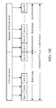
- FIG. 1B depicts the repeated TFCI code word when the minimum TTI is two radio frames.
- the objective of the present invention is to provide a transmission control mechanism for circuit-switched speech services in which the minimum TTI is two radio frames.
- the transmission control mechanism of the present invention the user device only use the first 15 non-transmission gap (non-TG) data slots within two radio frames of UL DPDCH to carry user data. Therefore, the present invention can reduce the power consumption in the user device in such a case that a downlink data frame is successfully and early decoded or the base station also use the first 15 non-transmission gap (non-TG) data slots within two radio frames of DL DPDCH to carry the downlink data.
- the present invention discloses a handheld device which comprises a processor and a transceiver.
- the processor is configured to generate an uplink signal according to a transmission type.
- the transceiver is electrically connected to the processor and configured to transmit the uplink signal to a base station.
- the uplink signal comprises an uplink dedicated physical data channel (UL DPDCH) having 15 non-transmission gap (non-TG) data slots within two radio frames to carry user data.
- UL DPDCH uplink dedicated physical data channel
- the present invention further discloses a transmission control method for use in a handheld device.
- the handheld device comprises a processor and a transceiver.
- the transceiver is electrically connected to the processor.
- the transmission control method comprises the following steps:
- the present invention further discloses a base station which comprises a transceiver and a processor.
- the transceiver is configured to receive an uplink signal from a handheld device.
- the uplink signal comprises an uplink dedicated physical data channel (UL DPDCH) having 15 non-transmission gap (non-TG) data slots within two radio frames to carry user data.
- the processor is electrically connected to the transceiver and configured to retrieve the user data from the 15 non-transmission gap (non-TG) data slots.
- the present invention further discloses a transmission control method for use in a base station.
- the base station comprises a transceiver and a processor.
- the processor is electrically connected to the transceiver.
- the transmission control method comprises the following steps:
- the present invention provides a handheld device, a base station and transmission control methods thereof.
- the present invention will be explained with reference to embodiments thereof. It shall be appreciated that, theses embodiments of the present invention are not intended to limit the present invention to any specific environment, applications or implementations described in these embodiments. Therefore, the description of these embodiments is only for purpose of illustration rather than to limit the present invention and the scope claimed in this application shall be governed by the claims. Additionally, in the following embodiments and the attached drawings, elements unrelated to the present invention are omitted from depiction; and dimensional relationships among individual elements in the attached drawings are illustrated only for ease of understanding, but not to limit the actual scale.
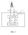
- FIG. 2 is a schematic diagram of a handheld device 2 .
- the handheld device 2 communicates with a base station 5.
- the handheld device 2 may be a smart phone, a tablet computer, or any other device with communication capability. It shall be noted that for the purpose of simplicity, other elements of the handheld device 2 , such as a display module, an antenna module, a power module and elements less related to the present invention, are all omitted from depiction herein.
- the handheld device 2 comprises a processor 201 and a transceiver 203 .
- the transceiver 203 is electronically connected to the processor 201 .
- the processor 201 When the handheld device 2 communicates with the base station 5 , the processor 201 generates an uplink signal 202 according to a transmission type (hereinafter called the first transmission type).
- the transceiver 203 transmits the uplink signal 202 to the base station 5 and receives a downlink signal 204 from the base station 5 simultaneously.
- the uplink signal 202 comprises an uplink dedicated physical data channel (UL DPDCH).
- the UL DPDCH In the first transmission type, the UL DPDCH has only 15 non-transmission gap (non-TG) data slots within two radio frames to carry user data.
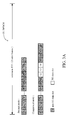
- 3A shows the UL DPDCH structures according to the first transmission type of the present invention in both of the normal mode and the compressed mode defined in the UMTS-FDD Release 99 specification. It is noted that each of the data slots or the control slots herein are respectively designated by Slot #1 to Slot #30 within 2 radio frames. Since every data slot is a non-TG data slot in normal mode, the first 15 data slots of the UL DPDCH of the uplink signal 202 within a minimum TTI (e.g. two radio frames) carry user data.
- a minimum TTI e.g. two radio frames
- the compressed mode has a period of time corresponding to some TG data slots within a minimum TTI and the period of time is used for measurement purpose.
- the user data are only carried by the non-TG data slots.
- the UL DPDCH of the uplink signal 202 carries user data in the first 15 non-TG data slot (i.e., Slot #1 to Slot #11 and Slot #15 to Slot #18) .
- FIG. 3B shows another transmission type (hereinafter called the second transmission type) of the present invention in both the normal mode and compressed mode.
- the structure of the UL DPDCH in the second transmission type is the same structure with 20 ms TTI as defined in the UMTS-FDD Release 99.
- all non-TG data slots within the two radio frames of the UL DPDCH are used for carrying user data as shown in FIG. 3B .
- the normal mode no TG data slot
- all 30 data slots within two radio frames are used for carrying user data.
- in compressed mode only non-TG data slots within two radio frame are used for carrying user data.
- the user data are carried in the 27 non-TG data slots excluding Slot #11 to Slot #13.
- N data is a number of data bits carried in a single non-TG data slot of the first 15 non-TG data slots
- SF the spreading factor applied to the UL DPDCH.
- each handheld device can communicate with more than one base station simultaneously with the same UL DPCH.
- the handheld device 2 can communicate not only with the base station 5 but also with other base station simultaneously with the same UL DPCH during soft handover.
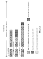
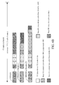
- FIGs. 4A-4B A second embodiment of the present invention is depicted in FIGs. 4A-4B .
- the uplink signal 202 of the present invention further comprises an uplink dedicated physical control channel (UL DPCCH).
- UL DPCCH uplink dedicated physical control channel
- FIG. 4A depicts the UL DPDCH and the UL DPCCH within the 2 radio frames in the normal mode.
- FIG. 4B depicts the UL DPDCH and the UL DPCCH within the 2 radio frames in the compressed mode.
- the UL DPCCH has at least 15 non-TG control slots within the 2 radio frames.
- Each of the at least 15 non-TG control slots has a transport format combination indicator (TFCI) field.
- the TFCI fields of first 10 non-TG control slots of the at least 15 non-TG control slots carry a TFCI code word
- the TFCI fields of remaining non-TG control slots of the at least 15 non-TG control slots carry acknowledgement (ACK) information for downlink data frame early termination.
- the ACK information comprises a plurality of 2-bit indications, each of which is carried in one of the remaining non-TG control slots and represents either an acknowledgement (ACK) indication or a negative-acknowledgment (NACK) indication.
- each non-TG control slot has three fields which includes the pilot field, the transport format combination indicator (TFCI) field and the transmit power control (TPC) field, but excludes the FBI field.
- the TFCI field carries 2 bits
- the pilot field carries 6 bits
- the TPC field carries 2bits. Since the present invention only focuses on the information carried in the TFCI field, the pilot field and the TPC field are not further described herein.
- the processor 201 fills the ACK information from Slot #11, depending on whether the downlink data frame of the downlink signal 204 has been successfully decoded.
- the situation I in FIG. 4A shows that the downlink data frame of the downlink signal 204 has been successfully decoded before the time point of Slot #15, and thus the number of the used control slots are identical to that of the used data slots.
- the situation II in FIG. 4A shows that the downlink data frame of the downlink signal 204 may have been successfully decoded after the time point of Slot #15, and thus, the number of the used control slots are larger than that of the used data slots.
- the number of the used control slots depends on when the processor 201 has decoded the downlink data frame of the downlink signal 204 successfully.
- FIG. 4B shows there are three TG slots (e.g., Slot #10 to Slot #12) in the compressed mode.
- the first 10 non-TG control slots i.e., Slot #1 to Slot #9 and Slot# 13
- the downlink data frame of the downlink signal 204 has been successfully decoded before the time point of Slot #18, and thus the number of the used control slots are identical to that of the used data slots.
- the downlink data frame of the downlink signal 204 may have been successfully decoded after the time point of Slot #18, and thus, the number of the used control slots are larger than that of the used data slots.
- the number of the used control slots depends on when the processor 201 has decoded the downlink data frame of the downlink signal 204 successfully.
- the TFCI code word in the present invention is a truncated 20-bit TFCI code word from a 32-bit TFCI code word corresponding to a 10-bit TFCI information.
- the 10-bit TFCI information may be encoded with the Reed-Muller code into the 32-bit TFCI code word, and then each TFCI field of the first 10 non-TG control slots carries 2 bits of the truncated 20-bit TFCI code.
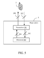
- FIG. 5 is a schematic diagram of the base station 5 .
- the base station 5 comprises a transceiver 501 and a processor 503 .
- the transceiver 501 transmits the downlink signal 204 to the handheld device 2 and receives the uplink signal 202 from the handheld device 2 .
- the processor 503 is electrically connected to the transceiver 501 and configured to retrieve the user data from the 15 non-TG data slots within every two radio frames of the UL DPDCH of the uplink signal 202 , generate the downlink signal 204 and enable the transceiver 501 to terminate transmission of the downlink data frame of the downlink signal 204 according to the ACK information.
- the TFCI fields of remaining non-TG control slots carry ACK information.
- the ACK information comprises a plurality of 2-bit indications.
- Each 2-bit indication is carried in the TFCI field of a non-TG control slot of the remaining non-TG control slots and may be an ACK indication or a negative-acknowledgment (NACK) indication based on whether the downlink data frame of the downlink signal 204 has been successfully decoded yet.
- the processor 201 defines a single 2-bit indication (ACK indication or NACK indication) as an ACK command.
- ACK indication or NACK indication as an ACK command.
- the processor 201 fills the NACK indication into every non-TG control slot in which the downlink data frame of the downlink signal 204 has not been successfully decoded by the processor 201 .
- the processor 201 fills the ACK indication into every non-TG control slot in which the downlink data frame of the downlink signal 204 has been successfully decoded by the process 201 .
- the 2-bit NACK indications are carried in Slot #11 to Slot #12 and the 2-bit ACK indications are carried in Slot #13 to Slot #15 in normal mode. In this case, the downlink data frame of the downlink signal 204 has not been successfully decoded until the time point of Slot #13.
- the 2-bit NACK indications are carried in Slot #11 to Slot #17 and the 2-bit ACK indication is carried in Slot #18 in normal mode.
- the downlink data frame of the downlink signal 204 has not been successfully decoded until the time point of Slot #18.
- FIG. 6B shows there are three TG slots (e.g., Slot #10 to Slot #12) in the compressed mode.
- the 2-bit NACK indications are carried in Slot #14 to Slot #15 and 2-bit ACK indications are carried in Slot #16 to Slot #18.
- the downlink data frame of the downlink signal 204 has not been successfully decoded until the time point of Slot #16.
- the situation II of FIG. 6B depicts that the 2-bit NACK indications are carried in Slot #14 to Slot #19 and the 2-bit ACK indication is carried in Slot #20. In this case, the downlink data frame of the downlink signal 204 has not been successfully decoded until the time point of Slot #20.
- the processor 201 may further boost a transmission power of the ACK indications so that the transmission power of the ACK indications is larger than that of the NACK indications. Due to the power enhancement in the ACK indications, the base station 5 is capable of more accurately detecting the ACK indications so that the base station 5 can terminate the transmission of the downlink data frame of the downlink signal 204 according to the ACK indications.
- FIGs. 7A , 7B and 7C A fifth embodiment of the present invention is shown in FIGs. 7A , 7B and 7C .
- the processor 201 defines two 2-bit indications (two ACK indications or two NACK indications) as an ACK command.
- every two of the 2-bit indications carried in two successive non-TG control slots of the remaining non-TG control slots constitutes an ACK command.
- the processor 201 fills the NACK indications into the two successive non-TG control slots in which the downlink data frame of the downlink signal 204 has not been successfully decoded by the processor 201 .
- the processor 201 executes the following operations: (a) filling the ACK indications into the two successive non-TG control slots which correspond to two non-TG data slots of the 15 non-TG data slots and in which the downlink data frame of the downlink signal 204 has been successfully decoded by the processor 201 ; (b) filling the ACK indication into the two successive non-TG control slots which are without corresponding to two non-TG data slots of the 15 non-TG data slots and in which the downlink data frame of the downlink signal 204 has been successfully decoded by the processor 201 unless the previous two successive non-TG control slots are filled with the ACK indication; and (c) filling the ACK indication into a last non-TG control slot of the remaining non-TG slot which corresponds to a last non-TG data slot of the 15 non-TG data slots and in which the previous two successive non-TG control slots are filled with the ACK indication.
- the processor 201 further fills the NACK indication into the last non-TG control slot of the remaining non-TG slots corresponding to a last slot within two radio frames when its previous two successive non-TG control slots are filled with the NACK indication.
- the processor 201 shall always fill the NACK indication regardless of whether the downlink data frame of the downlink signal 204 has been decoded successfully yet since it has no followed up non-TG control slot to constitute an ACK command with it.
- the processor 201 fills the NACK indication or the ACK indication into the last non-TG control slot in the minimum TTI depending on whether the downlink data frame of the downlink signal 204 has been decoded successfully yet. Specifically, the processor 201 further fills the NACK indication into the last non-TG control slot of the remaining non-TG slots which corresponds to the last slot within two radio frames and in which the downlink data frame has not been successfully decoded by the processor, and fills the ACK indication into the last non-TG control slot of the remaining non-TG slots which corresponds to the last slot within two radio frames and in which the downlink data frame has successfully decoded and the previous two successive non-TG control slots are filled with the NACK indication.
- the 2-bit NACK indications are carried in Slot #11 to Slot #12 and the 2-bit ACK indications are carried in Slot #13 to Slot #15 in the normal mode.
- the two 2-bit NACK indications carried in Slot #11 and Slot #12 constitute an ACK command
- the two 2-bit ACK indications carried in Slot #13 and Slot #14 constitute an ACK command
- the downlink data frame of the downlink signal 204 may have been successfully decoded at the time point of Slot #12 or Slot #13.
- the processor 201 has to fill the NACK indication into Slot #12 to make the ACK command constituted by the two 2-bit NACK indications carried in Slot #11 and Slot #12 complete.
- Slot #15 of DPCCH is filled with the 2-bit ACK indication since it is the last non-TG control slot of the remaining non-TG slot corresponding to the last non-TG data slot of the 15 non-TG data slots and its previous two consecutive non-TG control slots (i.e. Slot #13 and Slot #14) are filled with the ACK indication.
- the situation II in FIG. 7A shows that the 2-bit NACK indications are carried in Slot #11 to Slot #14 in the normal mode.
- the two 2-bit NACK indications carried in Slot #11 and Slot #12 constitute an ACK command
- the two 2-bit NACK indications carried in Slot #13 and Slot #14 constitute an ACK command
- the two 2-bit ACK indications carried in Slot #15 and Slot #16 constitute an ACK command
- the downlink data frame of the downlink signal 204 may have been successfully decoded at the time point of Slot #14 or Slot #15.
- the processor 201 has to fill the NACK indication into Slot #14 to make the ACK command constituted by the two 2-bit NACK indications carried in Slot #13 and Slot #14 complete.
- FIG. 7B depicts the UL DPDCH and the UL DPCCH of the uplink signal 202 transmitted in the compressed mode of the present embodiment.
- the situation I in FIG. 7B shows that the two 2-bit NACK indications carried in Slot #11 and in Slot #16 constitutes an ACK command.
- the processor 201 fills 2-bit ACK indications into Slot #17 to Slot #19 in which the downlink data frame of the downlink signal 204 has been decoded successfully. In this case, the downlink data frame of the downlink signal 204 may have been successfully decoded at the time point of Slot #16 or Slot #17.
- the 2-bit NACK indications are carried in Slot #11 and Slot #16 to Slot #18. Since the two 2-bit NACK indications carried in Slot #11 and in Slot #16 constitute an ACK command, the two 2-bit NACK indications carried in Slot #17 and Slot #18 constitute an ACK command, and the two 2-bit ACK indications carried in Slot #19 and Slot #20 constitute an ACK command, the downlink data frame of the downlink signal 204 may have been successfully decoded at the time point of Slot #18 or Slot #19.
- the situation I of FIG. 7C shows that the downlink data frame of downlink signal 204 has not been successfully decoded at the time point of Slot #28.
- the processor 201 since the two 2-bit NACK indications carried in Slot #28 and Slot #29 constitute an ACK command, the processor 201 further fills a 2-bit NACK indication into Slot #30, which is the last non-TG control slot of the remaining non-TG slots corresponding to the last slot within two radio frames (a minimum TTI) and in which the previous two successive non-TG control slots (i.e., Slot #28 and Slot 29) are filled with the NACK indication.
- the processor 201 still fills the NACK indication into Slot #30 even though the downlink data frame of downlink signal 204 may have been decoded at the time point of Slot #29 or Slot #30.
- the downlink data frame of downlink signal 204 may have not been decoded successfully until the time point of Slot #29 or Slot #30.
- the processor fills the 2-bit ACK into Slot#30 if the downlink data frame of downlink signal 204 have been decoded successfully at the time point of Slot #29 or Slot #30.
- the processor 201 fills the 2-bit NACK indication into Slot #30, since the downlink data frame of downlink signal 204 has not been successfully decoded within the minimum TTI.
- the processor 201 might not be able to fill the 2-bit ACK indications into two successive non-TG control slots in which the downlink data frame of downlink signal 204 has just been successfully decoded. In this case, the processor 201 would fill the 2-bit NACK indications into two successive non-TG control slots.
- the downlink data frame of downlink signal 204 may have been successfully decoded at the time point of Slot #11; however, the processor 201 _still fills the NACK indications into Slot #11 and Slot #12 since it is too late to fill the 2-bit ACK indications into Slot #11 and Slot #12.
- the downlink data frame of downlink signal 204 may have been successfully decoded at the time point of Slot #17.
- the downlink data frame of downlink signal 204 may have been successfully decoded at the time point of Slot #28.
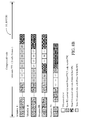
- FIG. 8A A sixth embodiment of the present invention is shown in FIG. 8A .
- the processor 201 also defines two 2-bit indications (two ACK indications or two NACK indications) as an ACK command; however, every two of the 2-bit indications carried in two consecutive non-TG control slots of the remaining non-TG control slots constitutes an ACK command.
- the present embodiment defines every two consecutive control slots which start with an odd-numbered slot as a command unit and each command unit may constitute an ACK command.
- the processor 201 fills the ACK indications and the NACK indications by the same way as described in the fifth embodiments.
- the compressed mode there are various situations based on the number of the TG control slots. For those slots of a command unit which are fully occupied by TG or TFCI transmission and fail to constitute an ACK command, the processor 201 ignores the ACK command insertion. Beside, for those slots of a command unit which are partially occupied by TG or TFCI and fails to constitute an ACK command, the processor 201 fills the NACK indications into the non-occupied slots of these slots.
- the processor 201 fills the NACK indications into the two consecutive non-TG control slots in which the downlink data frame of the downlink signal 204 has not been successfully decoded by the processor 201 . Moreover, the processor 201 executes the following operations: (a) filling the ACK indications into the two consecutive non-TG control slots which correspond to two non-TG data slots of the 15 non-TG data slots and in which the downlink data frame of the downlink signal 204 has been successfully decoded by the processor 201 ; (b) filling the ACK indication into the two consecutive non-TG control slots which are without corresponding to two non-TG data slots of the 15 non-TG data slots and in which the downlink data frame of the downlink signal 204 has been successfully decoded by the processor 201 unless the previous two consecutive non-TG control slots are filled with the ACK indication; (c) filling the ACK indication into a last non-TG control slot of the remaining non-TG slot which corresponds to a last non-TG data slot of the 15 non-TG data
- the processor 201 further fills the NACK indication into the a non-TG control slot of the remaining non-TG slot which is an odd-numbered slot and has no follow-up non-TG control slot, and fills the NACK indication into a non-TG control slot of the remaining non-TG slot which is an even-numbered slot and without a preceding non-TG control slot of the remaining non-TG slots.
- the processor 201 fills the NACK indication into a non-TG control slot of the remaining non-TG slot, which is an even-numbered slot and without a preceding non-TG control slot of the remaining non-TG slot, or which is an odd-numbered slot and without a follow-up non-TG control slot of the remaining non-TG slots, regardless of whether the downlink data frame of the downlink signal 204 has been successfully and early decoded yet.
- the base station 5 may ignore the ACK commands in these slots and can take each ACK command which starts from an odd-numbered slot..
- the situation I in FIG. 8A shows that a NACK indication is filled into Slot #14 since it is an even-number slot and its preceding Slot #13 is not a non-TG control slot.
- the base station 5 can take Slot #15 and Slot #16 as an ACK command, Slot #17 and Slot #18 as an ACK command, and so on.
- the situation II in FIG. 8A shows that a NACK indication is filled into Slot #14 since Slot #14 is an even-number slot and its preceding Slot #13 is not a non-TG control slot of the remaining non-TG slots even though the downlink data frame of the downlink signal 204 may have been successfully decoded by the processor 201 at the time point of Slot #14.
- the base station 5 can take Slot #15 and Slot #16 as an ACK command and Slot #17 and Slot #18 as an ACK command.
- the situation III in FIG. 8A shows that Slot #13 is filled with the 2-bit NACK indication since its follow-up Slot #14 is a TG control slot and is unable to be constituted an ACK command with Slot #13.
- a NACK indication is filled into Slot #18 since it is an even-number slot and its preceding Slot #17 is not a non-TG control slot of the remaining non-TG slots even though the downlink data frame of the downlink signal 204 may have been successfully decoded by the processor 201at the time point of Slot #13 or Slot #18.
- the base station 5 can take Slot #11 and Slot #12 as an ACK command and Slot #19 and Slot #20 as an ACK command.
- a NACK indication is filled into Slot #18 which is an even-number slot and whose preceding Slot #17 is not a non-TG control slot, even though the downlink data frame of the downlink signal 204 has been successfully decoded.
- the situation V in FIG. 8A shows that a NACK indication is filled into Slot #14 since it is an even-number slot and its preceding Slot #13 carries TFCI code word.
- the processor 201 might not be able to fill the 2-bit ACK indications into two consecutive non-TG control slots in which the downlink data frame of downlink signal 204 has just been successfully decoded. In this case, the processor 201 would fill the 2-bit NACK indications into two consecutive non-TG control slots too late.
- the downlink data frame of downlink signal 204 may have been successfully decoded at the time point of Slot #17; however, the processor 201 _still fills the NACK indications into Slot #17 and Slot #18 since it is too late to fill the 2-bit ACK indications into Slot #17 and Slot #18.
- the downlink data frame of downlink signal 204 may be decoded successfully at the time point of Slot # 11; however, it is too late for the processor 201 to timely fill the ACK indications into Slot #11 and Slot #12.
- a seventh embodiment of the present invention is shown in FIG. 8B .
- the seventh embodiment is partially modified from the sixth embodiment of the present invention.
- those slots of a command unit which are partially occupied by TG or TFCI are still treated as an ACK command. Therefore, the processor 201 fills the ACK indication into the non-occupied slot of a command unit in which the downlink data frame of the downlink signal 204 has been successfully decoded by the processor 201 .
- the processor 201 fills the NACK indication into the non-occupied slot of a command unit in which the downlink data frame of the downlink signal 204 has not been successfully decoded by the processor 201 .
- the processor 201 fills a NACK indication into a non-TG control slot of the remaining non-TG slot which is an odd-numbered slot and has no follow-up non-TG control slot and in which the downlink data frame of the downlink signal 204 has not been successfully decoded by the processor 201 , and fills an ACK indication into a non-TG control slot of the remaining non-TG slot which is an odd-numbered slot and has no follow-up non-TG control slot and in which the downlink data frame of the downlink signal 204 has successfully decoded by the processor 201 .
- the processor 201 further fills a NACK indication into a non-TG control slot of the remaining non-TG slot which is an even-numbered slot and without a preceding non-TG control slot of the remaining non-TG slots and in which the downlink data frame of the downlink signal 204 has not been successfully decoded by the processor 201 .
- the processor 201 fills an ACK indication into a non-TG control slot of the remaining non-TG slot which is an even-numbered slot and without a preceding non-TG control slot of the remaining non-TG slots and in which the downlink data frame of the downlink signal 204 has been successfully decoded by the processor 201 .
- the processor 201 fills an ACK or a NACK indication into a non-TG control slot of the remaining non-TG slot which is an even-numbered slot and without a preceding non-TG control slot of the remaining non-TG slots, or which is an odd-numbered slot and without a follow-up non-TG control slot of the remaining non-TG slots.
- the base station 5 in this embodiment can also take the ACK command from an odd-numbered slot and its follow-up even-numbered slot as described in the sixth embodiment.
- Slot #14 is an even-numbered slot and its preceding slot #13 is a TG slot.
- Slot #14 is filled with a 2-bit NACK indication since the downlink data frame of the downlink signal 204 has not been decoded successfully at the time point of Slot #14.
- two 2-bit ACK indications carried in Slot #19 and Slot #20 is an ACK command, the downlink data frame of the downlink signal 204 has been successfully decoded at the time point of Slot #18 or Slot #19.
- the base station 5 can take every odd-numbered slot and its follow-up even-numbered slot as an ACK command.
- Situation II of FIG. 8B shows that Slot #13, which is an odd-numbered slot and whose follow-up Slot #14 is a TG-slot, is filled with a 2-bit NACK indication since the downlink data frame of downlink signal 204 has not been decoded successfully at the time point of Slot #13.
- a 2-bit ACK indication is further filled into Slot #18 since the downlink data frame of the downlink signal 204 has been decoded successfully at the time point of Slot #18.
- the processor 201 further fills two 2-bit ACK indications into Slot #19 and Slot #20 to complete an ACK commend.
- the base station 5 also can take every odd-numbered slot and its follow-up even-numbered slot as an ACK command.
- the situation III of FIG. 8B shows that Slot #18, which is an even-numbered slot and whose preceding slot #17 is a TG slot, is filled with a 2-bit ACK indication since the downlink data frame of downlink signal 204 has been decoded successfully at the time point of Slot #12 or Slot #13.
- the situation IV of FIG. 8B shows that Slot #14, which is an even-numbered slot and whose preceding slot #13 is not a non-TG control slot of the remaining non-TG slots, is filled with a 2-bit ACK indication since the downlink data frame of downlink signal 204 has been decoded successfully at the time point of Slot #14.
- the processor 201 might not be able to fill the 2-bit ACK indications into a non-TG control slot in which the downlink data frame of downlink signal 204 has just been successfully decoded by the processor 201 . In this case, the processor 201 would fill the 2-bit NACK indications into a non-TG control slots too late.
- the downlink data frame of downlink signal 204 may have been successfully decoded at the time point of Slot #13; however, the processor 201 _still fills the NACK indication into Slot #13 since it is too late to fill the 2-bit ACK indication into Slot #13.
- the downlink data frame of downlink signal 204 may be decoded successfully at the time point of Slot #11; however, the processor 201 still fills the NACK indications into Slot #11 and Slot #12 since it is too late for the processor 201 to timely fill the ACK indications into Slot #11 and Slot #12.
- the processor 201 may further boost a transmission power of the ACK indications so that the transmission power of the ACK indications is larger than that of the NACK indications. Due to the power enhancement in the ACK indications, the base station 5 is capable of more accurately detecting the ACK indications so that the base station 5 can terminate the transmission of the downlink data frame of the downlink signal 204 according to the ACK indications.
- An eighth embodiment of the present invention is an extension of the first to seventh embodiments.
- the TFCI code word on the UL DPCCH in this embodiment has indication information indicating the transmission type of the uplink signal 202 .
- the processor 201 may generates a radio resource control (RRC) message indicating the transmission type of the uplink signal 202 and the transceiver 203 transmits the RRC message to the base station 5 in an initial connection establishment procedure. Accordingly, the base station 5 can be informed of the transmission type via the RRC message or the TFCI code word.
- RRC radio resource control
- the processor 201 may further select the transmission type from two transmission types (i.e. the first transmission type and the second transmission type) so as to generate the uplink signal 202.
- the first transmission type of the present invention is depicted in FIG. 3A , which uses the first 15 non-TG data slots of 30 data slots within the 20 milliseconds TTI (i.e. two radio frames) to carry user data.
- the second transmission type of the present invention is depicted in FIG. 3B , which uses all non-TG data slots of 30 data slots within the 20 milliseconds TTI to carry user data, as depicted in FIG. 3B .
- the transmission power of the first 15 non-TG data slots in the first transmission type is larger than the transmission power of the non-TG data slots in the second transmission type.
- the processor 201 may select the second transmission type rather than the first transmission type and generate an uplink signal according to the second transmission type.
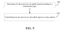
- a ninth embodiment of the present invention is a transmission control method, a flowchart diagram of which is shown in FIG. 9 .
- the transmission control method is for use in a handheld device, e.g., the handheld device 2 of the aforesaid embodiments.
- the handheld device comprises a processor and a transceiver.
- the transceiver is electrically connected to the processor.
- step 901 is executed by the processor to generate an uplink signal according to a transmission type.
- the uplink signal comprises an uplink dedicated physical data channel (UL DPDCH).
- the UL DPDCH has only 15 non-transmission gap (non-TG) data slots within two radio frames to carry user data.
- step 903 is executed by the transceiver of the handheld device to transmit the uplink signal to a base station.
- the uplink signal further comprises an uplink dedicated physical control channel (UL DPCCH).
- the UL DPCCH has at least 15 non-TG control slots within the two radio frames. Each of the at least 15 non-TG control slots has a transport format combination indicator (TFCI) field.
- TFCI transport format combination indicator
- the TFCI fields of first 10 non-TG control slots of the at least 15 non-TG control slots carry a TFCI code word, and the TFCI fields of remaining non-TG control slots of the at least 15 non-TG control slots carry acknowledgement (ACK) information for downlink data frame early termination.
- ACK acknowledgement
- the ACK information comprises a plurality of 2-bit indications.
- Each of the 2-bit indication is carried in one of the remaining non-TG control slots, and each of the 2-bit indication is one of an acknowledgement (ACK) indication and a negative-acknowledgment (NACK) indication.
- step 901 may further comprises the steps of filling the NACK indication into a non-TG control slot in which a downlink data frame has not been successfully decoded by the processor; and filling the ACK indication into a non-TG control slot in which the downlink data frame has been successfully decoded by the processor.
- step 901 may comprise the step of boosting a transmission power of the ACK indication so that the transmission power of the ACK indication is larger than a transmission 4power of the NACK indication.
- step 901 may further comprises the steps of: filling the NACK indications into the two successive slots in which the downlink data frame has not been successfully decoded by the processor; filling the ACK indications into the two successive non-TG control slots which correspond to two non-TG data slots of the 15 non-TG data slots and in which the downlink data frame has been successfully decoded by the processor; filling the ACK indication into the two successive non-TG control slots which are without corresponding to two non-TG data slots of the 15 non-TG data slots and in which the downlink data frame has been successfully decoded unless the previous two successive non-TG control slots are filled with the ACK indication; filling the ACK indication into a last non-TG control slot of the remaining non-TG slot corresponding to a last non-TG data slot of the 15 non-TG data slots when the two successive non-TG control slots previous to the last non
- step 901 may further comprises the steps of: filling, by the processor, the NACK indication into the two successive slots in which a downlink data frame has not been successfully decoded by the processor; filling, by the processor, the ACK indication into the two successive non-TG control slots which correspond to two non-TG data slots of the 15 non-TG data slots and in which the downlink data frame has successfully decoded by the processor; filling, by the processor, the ACK indication into the two successive non-TG control slots which are without corresponding to two non-TG data slots of the 15 non-TG data slots and in which the downlink data frame has successfully decoded by the processor unless previous two successive non-TG control slots are filled with the ACK indication; filling, by the processor, the ACK indication into a last non-TG control slot of the remaining non-TG slot corresponding to a last non-TG data slot of
- step 901 may further comprises the steps of: filling the NACK indications into the two consecutive slots in which a downlink data frame has not been successfully decoded by the processor; filling the ACK indications into the two consecutive non-TG control slots which correspond to two non-TG data slots of the 15 non-TG data slots and in which the downlink data frame has been successfully decoded by the processor ; filling the ACK indication into the two consecutive non-TG control slots which are without corresponding to two non-TG data slots of the 15 non-TG data slots and in which the downlink data frame has been successfully decoded by the processor unless the previous two consecutive non-TG control slots are filled with the ACK indication; filling the ACK indication into a last non-TG control slot of the remaining non-TG slot corresponding to a last non-TG data slot of the 15 non-TG data slots when the two consecutive non-TG control slots
- step 901 may further comprise the following steps of filling the NACK indication into the two consecutive slots in which a downlink data frame has not been successfully decoded by the processor ; filling the ACK indication into the two consecutive non-TG control slots which corresponds to two non-TG data slots of the 15 non-TG data slots and in which the downlink data frame has been successfully decoded by the processor ; filling the ACK indication into the two consecutive non-TG control slots which are without corresponding to two non-TG data slots of the 15 non-TG data slots and in which the downlink data frame has successfully decoded by the processor unless the previous two consecutive non-TG control slots are filled with the ACK indication; filling the ACK indication into a last non-TG control slot of the remaining non-TG slot corresponding to a last non-TG data slot of the 15 non-TG data slots when the two consecutive non-TG control slots
- the transmission control method may further comprise the steps of: generating, by the processor, a radio resource control (RRC) message indicating the transmission type; and transmitting, by the transceiver, the RRC message to the base station in an initial connection establishment procedure.
- RRC radio resource control
- the TFCI code word may have the indication information to indicate the transmission type.
- the transmission control method of the present invention may further comprise the step of: selecting, by the processor, the transmission type from two transmission types so as to generate the uplink signal.
- the transmission control method of the present embodiment can also execute all the operations and corresponding functions set forth in the first to eighth embodiment. How to execute these operations and functions will be readily appreciated by those of ordinary skill in the art based on the explanation of the first to sixth embodiments, and thus will not be further described herein.
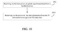
- a tenth embodiment of the present invention is a transmission control method, a flowchart diagram of which is shown in FIG. 10 .
- the transmission control method is for use in a base station, e.g., the base station 5 of the first to sixth embodiments.
- the base station comprises a transceiver and a processor.
- the transceiver is electrically connected to the processor.
- step 1001 is executed by the transceiver to receive an uplink signal transmitted from a handheld device.
- the uplink signal comprises an uplink dedicated physical data channel (UL DPDCH).
- the UL DPDCH has only 15 non-transmission gap (non-TG) data slots within two radio frames to carry data information.
- step 1003 is executed by the processor to retrieve the user data from the 15 non-transmission gap (non-TG) data slots.
- the uplink signal further comprises an uplink dedicated physical control channel (UL DPCCH).
- the UL DPCCH has at least 15 non-TG control slots within the two radio frames.
- Each of at least 15 non-TG control slots has a transport format combination indicator (TFCI) field.
- the TFCI fields of first 10 non-TG control slots of the at least 15 non-TG control slots carry a TFCI code word, and the TFCI fields of remaining non-TG control slots of the at least 15 non-TG control slots carry acknowledgement (ACK) information for downlink data frame early termination.
- ACK acknowledgement
- the transmission control method of this embodiment can further comprise the steps of: generating, by the processor, a downlink signal; transmitting, by the transceiver, the downlink signal to the handheld device; and enabling, by the processor, the transceiver to terminate transmission of a downlink data frame of the downlink signal according to the ACK information.
- the transmission control method of the present invention may further comprise the steps of: receiving, by the transceiver, a radio resource control (RRC) message indicating the transmission type from the handheld device in an initial connection establishment procedure.
- RRC radio resource control
- the TFCI code word may have the indication information to indicate the transmission type.
- the handheld device generates the uplink signal based on the transmission type and the transmission type may be selected from two transmission types.
- the transmission control method of the present embodiment can also execute all the operations and corresponding functions set forth in the first to eighth embodiments. How to execute these operations and functions will be readily appreciated by those of ordinary skill in the art based on the explanation of the first to sixth embodiment, and thus will not be further described herein.
- the transmission control mechanism of the present invention can reduce the power consumption in the user device in such a case that downlink data is successfully and early decoded or the base station also use the first 15 non-transmission gap (non-TG) data slots in two radio frames of DL DPDCH to carry the downlink data.
- the base station can terminate the transmission of the downlink data frame of the downlink signal to the handheld device and reallocate the transmission power of different downlink signals for multiple user devices so as to reduce the interference among the downlink signals.
Landscapes
- Engineering & Computer Science (AREA)
- Signal Processing (AREA)
- Computer Networks & Wireless Communication (AREA)
- Mobile Radio Communication Systems (AREA)
Abstract
Description
- Not applicable.
- The present invention relates to a handheld device, a base station and transmission control methods thereof. More particularly, the handheld device of the present invention transmits an uplink signal with an uplink dedicated physical data channel (UL DPDCH) in which only first 15 non-transmission gap (non-TG) data slots within two radio frames carry user data.
- With the development of wireless communication technologies, wireless devices have been widely used. To satisfy users' demand for speech service, various telecommunication standards have been developed. Universal mobile telecommunications system frequency division duplex (UMTS-FDD) Release 99 is a version of the third generation (3G) communication system. The UMTS-FDD Release 99 provides circuit-switched speech service in which a circuit-switched connection is established between a user device and a base station. User data and physical layer control information are carried on dedicated physical channels (DPCHs) of the uplink signal and the downlink signal, and the uplink signal and the downlink signal are respectively transmitted in different frequency bands at the same time.
-
FIG. 1A is a schematic diagram of the uplink signal in a radio frame with 15 slots as defined in the UMTS-FDD Release 99 specification. The DPCH of the uplink signal includes a dedicated physical data channel (DPDCH) carrying user data and a dedicated physical control channel (DPCCH) carrying physical layer control information. In each slot, the DPCCH comprises a pilot field, a transport format combination indication (TFCI) field, a feedback indication (FBI) field and a transmit power control (TPC) field. In addition, the minimum transmission time interval (minimum TTI) defined in the UMTS-FDD Release 99 specification may be one, two or four radio frames. In the case that the minimum TTI is two or four radio frames, first 30 bits of the TFCI code word are repeatedly carried in each radio frame in the minimum TTI. For example,FIG. 1B depicts the repeated TFCI code word when the minimum TTI is two radio frames. - However, power saving is a critical issue for the user device. Accordingly, an urgent need exists in the art to provide a transmission mechanism for reducing the power consumption in the user device.
- The objective of the present invention is to provide a transmission control mechanism for circuit-switched speech services in which the minimum TTI is two radio frames. By the transmission control mechanism of the present invention, the user device only use the first 15 non-transmission gap (non-TG) data slots within two radio frames of UL DPDCH to carry user data. Therefore, the present invention can reduce the power consumption in the user device in such a case that a downlink data frame is successfully and early decoded or the base station also use the first 15 non-transmission gap (non-TG) data slots within two radio frames of DL DPDCH to carry the downlink data.
- To achieve the aforesaid objective, the present invention discloses a handheld device which comprises a processor and a transceiver. The processor is configured to generate an uplink signal according to a transmission type. The transceiver is electrically connected to the processor and configured to transmit the uplink signal to a base station. The uplink signal comprises an uplink dedicated physical data channel (UL DPDCH) having 15 non-transmission gap (non-TG) data slots within two radio frames to carry user data.
- In addition, the present invention further discloses a transmission control method for use in a handheld device. The handheld device comprises a processor and a transceiver. The transceiver is electrically connected to the processor. The transmission control method comprises the following steps:
- (a) generating, by the processor, an uplink signal according to a transmission mode, wherein the uplink signal comprises an uplink dedicated physical data channel (UL DPDCH) having 15 non-transmission gap (non-TG) data slots within two radio frames to carry user data; and
- (b) transmitting, by the transceiver, the uplink signal to a base station.
- Besides, in order to achieve the aforesaid objective, the present invention further discloses a base station which comprises a transceiver and a processor. The transceiver is configured to receive an uplink signal from a handheld device. The uplink signal comprises an uplink dedicated physical data channel (UL DPDCH) having 15 non-transmission gap (non-TG) data slots within two radio frames to carry user data. The processor is electrically connected to the transceiver and configured to retrieve the user data from the 15 non-transmission gap (non-TG) data slots.
- Moreover, the present invention further discloses a transmission control method for use in a base station. The base station comprises a transceiver and a processor. The processor is electrically connected to the transceiver. The transmission control method comprises the following steps:
- (a) receiving, by the transceiver, an uplink signal transmitted from a handheld device, wherein the uplink signal comprises an uplink dedicated physical data channel (UL DPDCH) having 15 non-transmission gap (non-TG) data slots within two radio frames to carry user data; and
- (b) retrieving, by the processor, the user data from the 15 non-transmission gap (non-TG) data slots.
- The detailed technology and preferred embodiments implemented for the subject invention are described in the following paragraphs accompanying the appended drawings for people skilled in this field to well appreciate the features of the claimed invention.
-
-
FIG. 1A is a schematic diagram of the uplink signal with 15 slots over a radio frame in accordance with the present UMTS-FDD Release 99 specification; -
FIG. 1B is a schematic diagram showing the repeated TFCI code word in the case that the minimum TTI is two radio frames -
FIG. 2 is a schematic view of ahandheld device 2 according to the first embodiment to the fourth embodiment of the present invention; -
FIGs. 3A-3B respectively depict different structures of the uplink dedicated physical data channel (UL DPDCH) of two transmission types in the normal mode and the compressed mode according to the first embodiment of the present invention; -
FIGs. 4A-4B respectively depict the UL DPDCH and the UL DPCCH of the uplink signal in the normal mode and the compressed mode according to the second embodiment of the present invention; -
FIG. 5 is a schematic view of abase station 5 according to the third embodiment of the present invention; -
FIGs. 6A-6B respectively depict the UL DPDCH and the UL DPCCH of the uplink signal in the normal mode and the compressed mode according to the fourth embodiment of the present invention; -
FIGs. 7A-7C respectively depict the UL DPDCH and the UL DPCCH of the uplink signal in the normal mode and the compressed mode according to the fifth embodiment of the present invention; -
FIG. 8A depicts the UL DPCCH of the uplink signal in the compressed mode under different situations according to the sixth embodiment of the present invention; -
FIG. 8B depicts the UL DPCCH of the uplink signal in the compressed mode under different situations according to the seventh embodiment of the present invention; -
FIG. 9 is a flowchart diagram of a transmission control method according to the ninth embodiment of the present invention; and -
FIG. 10 is a flowchart diagram of a transmission control method according to the tenth embodiment of the present invention. - The present invention provides a handheld device, a base station and transmission control methods thereof. In the following description, the present invention will be explained with reference to embodiments thereof. It shall be appreciated that, theses embodiments of the present invention are not intended to limit the present invention to any specific environment, applications or implementations described in these embodiments. Therefore, the description of these embodiments is only for purpose of illustration rather than to limit the present invention and the scope claimed in this application shall be governed by the claims. Additionally, in the following embodiments and the attached drawings, elements unrelated to the present invention are omitted from depiction; and dimensional relationships among individual elements in the attached drawings are illustrated only for ease of understanding, but not to limit the actual scale.
- The first embodiment of the present invention is depicted in
FIG. 2 , which is a schematic diagram of ahandheld device 2. Thehandheld device 2 communicates with abase station 5. Thehandheld device 2 may be a smart phone, a tablet computer, or any other device with communication capability. It shall be noted that for the purpose of simplicity, other elements of thehandheld device 2, such as a display module, an antenna module, a power module and elements less related to the present invention, are all omitted from depiction herein. - The
handheld device 2 comprises aprocessor 201 and atransceiver 203. Thetransceiver 203 is electronically connected to theprocessor 201. When thehandheld device 2 communicates with thebase station 5, theprocessor 201 generates anuplink signal 202 according to a transmission type (hereinafter called the first transmission type). Thetransceiver 203 transmits theuplink signal 202 to thebase station 5 and receives adownlink signal 204 from thebase station 5 simultaneously. Theuplink signal 202 comprises an uplink dedicated physical data channel (UL DPDCH). In the first transmission type, the UL DPDCH has only 15 non-transmission gap (non-TG) data slots within two radio frames to carry user data.FIG. 3A shows the UL DPDCH structures according to the first transmission type of the present invention in both of the normal mode and the compressed mode defined in the UMTS-FDD Release 99 specification. It is noted that each of the data slots or the control slots herein are respectively designated bySlot # 1 to Slot #30 within 2 radio frames. Since every data slot is a non-TG data slot in normal mode, the first 15 data slots of the UL DPDCH of theuplink signal 202 within a minimum TTI (e.g. two radio frames) carry user data. - Compared to the normal mode, the compressed mode has a period of time corresponding to some TG data slots within a minimum TTI and the period of time is used for measurement purpose. In this case, the user data are only carried by the non-TG data slots. For example, in the case that there are three TG data slots within the first 15 data slots (i.e.,
Slot # 12 to Slot #14) in the compressed mode, the UL DPDCH of theuplink signal 202 carries user data in the first 15 non-TG data slot (i.e.,Slot # 1 to Slot #11 andSlot # 15 to Slot #18) . -
FIG. 3B shows another transmission type (hereinafter called the second transmission type) of the present invention in both the normal mode and compressed mode. The structure of the UL DPDCH in the second transmission type is the same structure with 20 ms TTI as defined in the UMTS-FDD Release 99. Unlike the first transmission type of the present invention, all non-TG data slots within the two radio frames of the UL DPDCH are used for carrying user data as shown inFIG. 3B . Specifically, in the normal mode (no TG data slot), all 30 data slots within two radio frames are used for carrying user data. And, in compressed mode, only non-TG data slots within two radio frame are used for carrying user data. For example, in the case there are three TG data slots (i.e.Slot # 11 to Slot #13) within the two radio frames, the user data are carried in the 27 non-TG data slots excludingSlot # 11 to Slot #13. - The following description will focus on the configuration of the first transmission type of the present invention. In detail, a spreading factor applied to the UL DPDCH according to the first transmission type may be determined by Equation 1:

where Ndata is a number of data bits carried in a single non-TG data slot of the first 15 non-TG data slots and SF is the spreading factor applied to the UL DPDCH. It can be appreciated that in the first transmission type, user data are only carried in the first 15 non-TG data slots within two radio frames. Thus, in the normal mode, the number of data bits carried in a single non-TG data slot of the first transmission type is double that of the second transmission type. This results in a smaller spreading factor applied to the UL DPDCH in the first transmission type compared to that applied to the UL DPDCH in the second transmission type. - Besides, a nominal power relation in the first transmission type of the present invention may be defined by Equation 2:

where Ajp is the nominal power relation in the first transmission type and Aj is a nominal power relation in the UMTS-FDD Release 99 and the second transmission type. Aj is defined by Equation 3:
where βd is a gain factor of the UL DPDCH and βc is a gain factor of the UL DPCCH. Since the nominal power relation Aj in the UMTS-FDD Release 99 has been well appreciated by a person having ordinary skill in this art, it will not be further described herein. - It should be appreciated that, during soft handover, each handheld device can communicate with more than one base station simultaneously with the same UL DPCH. In other words, the
handheld device 2 can communicate not only with thebase station 5 but also with other base station simultaneously with the same UL DPCH during soft handover. - A second embodiment of the present invention is depicted in
FIGs. 4A-4B . Theuplink signal 202 of the present invention further comprises an uplink dedicated physical control channel (UL DPCCH). For example,FIG. 4A depicts the UL DPDCH and the UL DPCCH within the 2 radio frames in the normal mode.FIG. 4B depicts the UL DPDCH and the UL DPCCH within the 2 radio frames in the compressed mode. - As shown in
FIGs 4A and4B , the UL DPCCH has at least 15 non-TG control slots within the 2 radio frames. Each of the at least 15 non-TG control slots has a transport format combination indicator (TFCI) field. The TFCI fields of first 10 non-TG control slots of the at least 15 non-TG control slots carry a TFCI code word, and the TFCI fields of remaining non-TG control slots of the at least 15 non-TG control slots carry acknowledgement (ACK) information for downlink data frame early termination. The ACK information comprises a plurality of 2-bit indications, each of which is carried in one of the remaining non-TG control slots and represents either an acknowledgement (ACK) indication or a negative-acknowledgment (NACK) indication. - In the present invention, each non-TG control slot has three fields which includes the pilot field, the transport format combination indicator (TFCI) field and the transmit power control (TPC) field, but excludes the FBI field. The TFCI field carries 2 bits, the pilot field carries 6 bits and the TPC field carries 2bits. Since the present invention only focuses on the information carried in the TFCI field, the pilot field and the TPC field are not further described herein.
- In the normal mode, the first 10 control slots within the two radio frames of the UL DPCCH carry the TFCI code word. Then, the
processor 201 fills the ACK information fromSlot # 11, depending on whether the downlink data frame of thedownlink signal 204 has been successfully decoded. The situation I inFIG. 4A shows that the downlink data frame of thedownlink signal 204 has been successfully decoded before the time point ofSlot # 15, and thus the number of the used control slots are identical to that of the used data slots. On the other hand, the situation II inFIG. 4A shows that the downlink data frame of thedownlink signal 204 may have been successfully decoded after the time point ofSlot # 15, and thus, the number of the used control slots are larger than that of the used data slots. In a word, the number of the used control slots depends on when theprocessor 201 has decoded the downlink data frame of thedownlink signal 204 successfully. - Similarly,
FIG. 4B shows there are three TG slots (e.g.,Slot # 10 to Slot #12) in the compressed mode. The first 10 non-TG control slots (i.e.,Slot # 1 to Slot #9 and Slot# 13) within the two radio frames of UL DPCCH carry the TFCI code word. In the situation I ofFIG. 4B , the downlink data frame of thedownlink signal 204 has been successfully decoded before the time point ofSlot # 18, and thus the number of the used control slots are identical to that of the used data slots. In situation II ofFIG. 4B , the downlink data frame of thedownlink signal 204 may have been successfully decoded after the time point ofSlot # 18, and thus, the number of the used control slots are larger than that of the used data slots. As described earlier, the number of the used control slots depends on when theprocessor 201 has decoded the downlink data frame of thedownlink signal 204 successfully. - It is note that the TFCI code word in the present invention is a truncated 20-bit TFCI code word from a 32-bit TFCI code word corresponding to a 10-bit TFCI information. For example, the 10-bit TFCI information may be encoded with the Reed-Muller code into the 32-bit TFCI code word, and then each TFCI field of the first 10 non-TG control slots carries 2 bits of the truncated 20-bit TFCI code.
- A third embodiment of the present invention is depicted in
FIG. 5 , which is a schematic diagram of thebase station 5. Thebase station 5 comprises atransceiver 501 and a processor 503. Thetransceiver 501 transmits thedownlink signal 204 to thehandheld device 2 and receives theuplink signal 202 from thehandheld device 2. The processor 503 is electrically connected to thetransceiver 501 and configured to retrieve the user data from the 15 non-TG data slots within every two radio frames of the UL DPDCH of theuplink signal 202, generate thedownlink signal 204 and enable thetransceiver 501 to terminate transmission of the downlink data frame of thedownlink signal 204 according to the ACK information. - A fourth embodiment of the present invention is depicted in
FIGs. 6A and6B . As aforementioned, the TFCI fields of remaining non-TG control slots carry ACK information. In the present invention, the ACK information comprises a plurality of 2-bit indications. Each 2-bit indication is carried in the TFCI field of a non-TG control slot of the remaining non-TG control slots and may be an ACK indication or a negative-acknowledgment (NACK) indication based on whether the downlink data frame of thedownlink signal 204 has been successfully decoded yet. In this embodiment, theprocessor 201 defines a single 2-bit indication (ACK indication or NACK indication) as an ACK command. Thus, each of the 2-bit indications carried in a single non-TG control slot of the remaining non-TG control slots constitutes an ACK command. - Specifically, the
processor 201 fills the NACK indication into every non-TG control slot in which the downlink data frame of the downlink signal 204has not been successfully decoded by theprocessor 201. By contrast, theprocessor 201 fills the ACK indication into every non-TG control slot in which the downlink data frame of thedownlink signal 204 has been successfully decoded by theprocess 201. For example, as shown in the situation I ofFIG. 6A , the 2-bit NACK indications are carried inSlot # 11 to Slot #12 and the 2-bit ACK indications are carried inSlot # 13 to Slot #15 in normal mode. In this case, the downlink data frame of thedownlink signal 204 has not been successfully decoded until the time point ofSlot # 13. In another example as shown in the situation II ofFIG. 6A , the 2-bit NACK indications are carried inSlot # 11 to Slot #17 and the 2-bit ACK indication is carried inSlot # 18 in normal mode. In this case, the downlink data frame of thedownlink signal 204 has not been successfully decoded until the time point ofSlot # 18. -
FIG. 6B shows there are three TG slots (e.g.,Slot # 10 to Slot #12) in the compressed mode. In the situation I ofFIG. 6B , the 2-bit NACK indications are carried inSlot # 14 to Slot #15 and 2-bit ACK indications are carried inSlot # 16 to Slot #18. In this case, the downlink data frame of thedownlink signal 204 has not been successfully decoded until the time point ofSlot # 16. The situation II ofFIG. 6B depicts that the 2-bit NACK indications are carried inSlot # 14 to Slot #19 and the 2-bit ACK indication is carried inSlot # 20. In this case, the downlink data frame of thedownlink signal 204 has not been successfully decoded until the time point ofSlot # 20. - In other embodiments, the
processor 201 may further boost a transmission power of the ACK indications so that the transmission power of the ACK indications is larger than that of the NACK indications. Due to the power enhancement in the ACK indications, thebase station 5 is capable of more accurately detecting the ACK indications so that thebase station 5 can terminate the transmission of the downlink data frame of thedownlink signal 204 according to the ACK indications. - A fifth embodiment of the present invention is shown in
FIGs. 7A ,7B and7C . In this embodiment, theprocessor 201 defines two 2-bit indications (two ACK indications or two NACK indications) as an ACK command. Thus, every two of the 2-bit indications carried in two successive non-TG control slots of the remaining non-TG control slots constitutes an ACK command. Specifically, theprocessor 201 fills the NACK indications into the two successive non-TG control slots in which the downlink data frame of thedownlink signal 204 has not been successfully decoded by theprocessor 201. Moreover, theprocessor 201 executes the following operations: (a) filling the ACK indications into the two successive non-TG control slots which correspond to two non-TG data slots of the 15 non-TG data slots and in which the downlink data frame of thedownlink signal 204 has been successfully decoded by theprocessor 201; (b) filling the ACK indication into the two successive non-TG control slots which are without corresponding to two non-TG data slots of the 15 non-TG data slots and in which the downlink data frame of thedownlink signal 204 has been successfully decoded by theprocessor 201 unless the previous two successive non-TG control slots are filled with the ACK indication; and (c) filling the ACK indication into a last non-TG control slot of the remaining non-TG slot which corresponds to a last non-TG data slot of the 15 non-TG data slots and in which the previous two successive non-TG control slots are filled with the ACK indication. Moreover, in a case that there are an odd number of TG slots in this minimum TTI in the compressed mode, theprocessor 201 further fills the NACK indication into the last non-TG control slot of the remaining non-TG slots corresponding to a last slot within two radio frames when its previous two successive non-TG control slots are filled with the NACK indication. - In other words, for the last non-TG control slot of the remaining non-TG slots, as long as it corresponds to the last slot in the minimum TTI and its previous two successive non-TG control slots filled with the NACK indication, the
processor 201 shall always fill the NACK indication regardless of whether the downlink data frame of thedownlink signal 204 has been decoded successfully yet since it has no followed up non-TG control slot to constitute an ACK command with it. - In other embodiment, the
processor 201 fills the NACK indication or the ACK indication into the last non-TG control slot in the minimum TTI depending on whether the downlink data frame of thedownlink signal 204 has been decoded successfully yet. Specifically, theprocessor 201 further fills the NACK indication into the last non-TG control slot of the remaining non-TG slots which corresponds to the last slot within two radio frames and in which the downlink data frame has not been successfully decoded by the processor, and fills the ACK indication into the last non-TG control slot of the remaining non-TG slots which corresponds to the last slot within two radio frames and in which the downlink data frame has successfully decoded and the previous two successive non-TG control slots are filled with the NACK indication. - For example, as shown in the situation I of
FIG. 7A , the 2-bit NACK indications are carried inSlot # 11 to Slot #12 and the 2-bit ACK indications are carried inSlot # 13 to Slot #15 in the normal mode. In this case, since the two 2-bit NACK indications carried inSlot # 11 andSlot # 12 constitute an ACK command and the two 2-bit ACK indications carried inSlot # 13 andSlot # 14 constitute an ACK command, the downlink data frame of thedownlink signal 204 may have been successfully decoded at the time point ofSlot # 12 orSlot # 13. In other words, even the downlink data frame of thedownlink signal 204 has been successfully decoded at the time point ofSlot # 12, theprocessor 201 has to fill the NACK indication intoSlot # 12 to make the ACK command constituted by the two 2-bit NACK indications carried inSlot # 11 andSlot # 12 complete. In addition,Slot # 15 of DPCCH is filled with the 2-bit ACK indication since it is the last non-TG control slot of the remaining non-TG slot corresponding to the last non-TG data slot of the 15 non-TG data slots and its previous two consecutive non-TG control slots (i.e.Slot # 13 and Slot #14) are filled with the ACK indication. - The situation II in
FIG. 7A shows that the 2-bit NACK indications are carried inSlot # 11 to Slot #14 in the normal mode. In this case, since the two 2-bit NACK indications carried inSlot # 11 andSlot # 12 constitute an ACK command, the two 2-bit NACK indications carried inSlot # 13 andSlot # 14 constitute an ACK command and the two 2-bit ACK indications carried inSlot # 15 andSlot # 16 constitute an ACK command, the downlink data frame of thedownlink signal 204 may have been successfully decoded at the time point ofSlot # 14 orSlot # 15. Similarly, even the downlink data frame of thedownlink signal 204 has been successfully decoded at the time point ofSlot # 14, theprocessor 201 has to fill the NACK indication intoSlot # 14 to make the ACK command constituted by the two 2-bit NACK indications carried inSlot # 13 andSlot # 14 complete. -
FIG. 7B depicts the UL DPDCH and the UL DPCCH of theuplink signal 202 transmitted in the compressed mode of the present embodiment. The situation I inFIG. 7B shows that the two 2-bit NACK indications carried inSlot # 11 and inSlot # 16 constitutes an ACK command. Afterwards, theprocessor 201 fills 2-bit ACK indications intoSlot # 17 to Slot #19 in which the downlink data frame of thedownlink signal 204 has been decoded successfully. In this case, the downlink data frame of thedownlink signal 204 may have been successfully decoded at the time point ofSlot # 16 orSlot # 17. - Similarly, as shown in situation II of
FIG. 7B , the 2-bit NACK indications are carried inSlot # 11 andSlot # 16 to Slot #18. Since the two 2-bit NACK indications carried inSlot # 11 and inSlot # 16 constitute an ACK command, the two 2-bit NACK indications carried inSlot # 17 andSlot # 18 constitute an ACK command, and the two 2-bit ACK indications carried inSlot # 19 andSlot # 20 constitute an ACK command, the downlink data frame of thedownlink signal 204 may have been successfully decoded at the time point ofSlot # 18 orSlot # 19. - In addition, the situation I of
FIG. 7C shows that the downlink data frame ofdownlink signal 204 has not been successfully decoded at the time point ofSlot # 28. In this case, since the two 2-bit NACK indications carried inSlot # 28 andSlot # 29 constitute an ACK command, theprocessor 201 further fills a 2-bit NACK indication intoSlot # 30, which is the last non-TG control slot of the remaining non-TG slots corresponding to the last slot within two radio frames (a minimum TTI) and in which the previous two successive non-TG control slots (i.e.,Slot # 28 and Slot 29) are filled with the NACK indication. In other words, theprocessor 201 still fills the NACK indication intoSlot # 30 even though the downlink data frame ofdownlink signal 204 may have been decoded at the time point ofSlot # 29 orSlot # 30. - As shown in the situation II of
FIG. 7C , the downlink data frame ofdownlink signal 204 may have not been decoded successfully until the time point ofSlot # 29 orSlot # 30. In this case, although the two 2-bit NACK indication carried inSlot # 28 andSlot # 29 constitute an ACK command andSlot # 30 has no follow up slot in this minimum TTI to constitute an ACK command with it, the processor fills the 2-bit ACK intoSlot# 30 if the downlink data frame ofdownlink signal 204 have been decoded successfully at the time point ofSlot # 29 orSlot # 30. Conversely, in the situation III ofFIG. 7C , theprocessor 201 fills the 2-bit NACK indication intoSlot # 30, since the downlink data frame ofdownlink signal 204 has not been successfully decoded within the minimum TTI. - In other embodiment, due to the performance of the
processor 201, theprocessor 201 might not be able to fill the 2-bit ACK indications into two successive non-TG control slots in which the downlink data frame ofdownlink signal 204 has just been successfully decoded. In this case, theprocessor 201 would fill the 2-bit NACK indications into two successive non-TG control slots. - For example, in the situation I of
FIG. 7A , the downlink data frame ofdownlink signal 204 may have been successfully decoded at the time point ofSlot # 11; however, the processor 201_still fills the NACK indications intoSlot # 11 andSlot # 12 since it is too late to fill the 2-bit ACK indications intoSlot # 11 andSlot # 12. In another example of the situation II ofFIG. 7B , the downlink data frame ofdownlink signal 204 may have been successfully decoded at the time point ofSlot # 17. In addition, in the situation II ofFIG. 7C , the downlink data frame ofdownlink signal 204 may have been successfully decoded at the time point ofSlot # 28. - A sixth embodiment of the present invention is shown in
FIG. 8A . In this embodiment, theprocessor 201 also defines two 2-bit indications (two ACK indications or two NACK indications) as an ACK command; however, every two of the 2-bit indications carried in two consecutive non-TG control slots of the remaining non-TG control slots constitutes an ACK command. In other words, the present embodiment defines every two consecutive control slots which start with an odd-numbered slot as a command unit and each command unit may constitute an ACK command. - In this embodiment, regarding the normal mode, the
processor 201 fills the ACK indications and the NACK indications by the same way as described in the fifth embodiments. However, regarding the compressed mode, there are various situations based on the number of the TG control slots. For those slots of a command unit which are fully occupied by TG or TFCI transmission and fail to constitute an ACK command, theprocessor 201 ignores the ACK command insertion. Beside, for those slots of a command unit which are partially occupied by TG or TFCI and fails to constitute an ACK command, theprocessor 201 fills the NACK indications into the non-occupied slots of these slots. - Specifically, the
processor 201 fills the NACK indications into the two consecutive non-TG control slots in which the downlink data frame of thedownlink signal 204 has not been successfully decoded by theprocessor 201. Moreover, theprocessor 201 executes the following operations: (a) filling the ACK indications into the two consecutive non-TG control slots which correspond to two non-TG data slots of the 15 non-TG data slots and in which the downlink data frame of thedownlink signal 204 has been successfully decoded by theprocessor 201; (b) filling the ACK indication into the two consecutive non-TG control slots which are without corresponding to two non-TG data slots of the 15 non-TG data slots and in which the downlink data frame of thedownlink signal 204 has been successfully decoded by theprocessor 201 unless the previous two consecutive non-TG control slots are filled with the ACK indication; (c) filling the ACK indication into a last non-TG control slot of the remaining non-TG slot which corresponds to a last non-TG data slot of the 15 non-TG data slots and in which the previous two consecutive non-TG control slots are filled with the ACK indication. In addition, theprocessor 201 further fills the NACK indication into the a non-TG control slot of the remaining non-TG slot which is an odd-numbered slot and has no follow-up non-TG control slot, and fills the NACK indication into a non-TG control slot of the remaining non-TG slot which is an even-numbered slot and without a preceding non-TG control slot of the remaining non-TG slots. - In this embodiment, the
processor 201 fills the NACK indication into a non-TG control slot of the remaining non-TG slot, which is an even-numbered slot and without a preceding non-TG control slot of the remaining non-TG slot, or which is an odd-numbered slot and without a follow-up non-TG control slot of the remaining non-TG slots, regardless of whether the downlink data frame of thedownlink signal 204 has been successfully and early decoded yet. As a result, thebase station 5 may ignore the ACK commands in these slots and can take each ACK command which starts from an odd-numbered slot.. - For example, the situation I in
FIG. 8A shows that a NACK indication is filled intoSlot # 14 since it is an even-number slot and its precedingSlot # 13 is not a non-TG control slot. In this case, thebase station 5 can takeSlot # 15 andSlot # 16 as an ACK command,Slot # 17 andSlot # 18 as an ACK command, and so on. On the other hand, the situation II inFIG. 8A shows that a NACK indication is filled intoSlot # 14 sinceSlot # 14 is an even-number slot and its precedingSlot # 13 is not a non-TG control slot of the remaining non-TG slots even though the downlink data frame of thedownlink signal 204 may have been successfully decoded by the processor 201at the time point ofSlot # 14. Similarly, in this case, thebase station 5 can takeSlot # 15 andSlot # 16 as an ACK command andSlot # 17 andSlot # 18 as an ACK command. - Furthermore, the situation III in
FIG. 8A shows thatSlot # 13 is filled with the 2-bit NACK indication since its follow-up Slot # 14 is a TG control slot and is unable to be constituted an ACK command withSlot # 13. In addition, a NACK indication is filled intoSlot # 18 since it is an even-number slot and its precedingSlot # 17 is not a non-TG control slot of the remaining non-TG slots even though the downlink data frame of thedownlink signal 204 may have been successfully decoded by the processor 201at the time point ofSlot # 13 orSlot # 18. In this case, thebase station 5 can takeSlot # 11 andSlot # 12 as an ACK command andSlot # 19 andSlot # 20 as an ACK command. - Similarly, as shown in the situation IV of
FIG. 8A , a NACK indication is filled intoSlot # 18 which is an even-number slot and whose precedingSlot # 17 is not a non-TG control slot, even though the downlink data frame of thedownlink signal 204 has been successfully decoded. In addition, the situation V inFIG. 8A shows that a NACK indication is filled intoSlot # 14 since it is an even-number slot and its precedingSlot # 13 carries TFCI code word. - As previously described, in other embodiment, due to the performance of the
processor 201, theprocessor 201 might not be able to fill the 2-bit ACK indications into two consecutive non-TG control slots in which the downlink data frame ofdownlink signal 204 has just been successfully decoded. In this case, theprocessor 201 would fill the 2-bit NACK indications into two consecutive non-TG control slots too late. - For example, in the situation I of
FIG 8A , the downlink data frame ofdownlink signal 204 may have been successfully decoded at the time point ofSlot # 17; however, the processor 201_still fills the NACK indications intoSlot # 17 andSlot # 18 since it is too late to fill the 2-bit ACK indications intoSlot # 17 andSlot # 18. In addition, taking the situation III ofFIG 8A as an example, the downlink data frame ofdownlink signal 204 may be decoded successfully at the time point ofSlot # 11; however, it is too late for theprocessor 201 to timely fill the ACK indications intoSlot # 11 andSlot # 12. - A seventh embodiment of the present invention is shown in
FIG. 8B . The seventh embodiment is partially modified from the sixth embodiment of the present invention. In this embodiment, those slots of a command unit which are partially occupied by TG or TFCI are still treated as an ACK command. Therefore, theprocessor 201 fills the ACK indication into the non-occupied slot of a command unit in which the downlink data frame of thedownlink signal 204 has been successfully decoded by theprocessor 201. Conversely, theprocessor 201 fills the NACK indication into the non-occupied slot of a command unit in which the downlink data frame of thedownlink signal 204 has not been successfully decoded by theprocessor 201. - In detail, the
processor 201 fills a NACK indication into a non-TG control slot of the remaining non-TG slot which is an odd-numbered slot and has no follow-up non-TG control slot and in which the downlink data frame of thedownlink signal 204 has not been successfully decoded by theprocessor 201, and fills an ACK indication into a non-TG control slot of the remaining non-TG slot which is an odd-numbered slot and has no follow-up non-TG control slot and in which the downlink data frame of thedownlink signal 204 has successfully decoded by theprocessor 201. In addition, theprocessor 201 further fills a NACK indication into a non-TG control slot of the remaining non-TG slot which is an even-numbered slot and without a preceding non-TG control slot of the remaining non-TG slots and in which the downlink data frame of thedownlink signal 204 has not been successfully decoded by theprocessor 201. Conversely, theprocessor 201 fills an ACK indication into a non-TG control slot of the remaining non-TG slot which is an even-numbered slot and without a preceding non-TG control slot of the remaining non-TG slots and in which the downlink data frame of thedownlink signal 204 has been successfully decoded by theprocessor 201. - In other words, based on whether the downlink data frame of the
downlink signal 204 has been decoded successfully yet, theprocessor 201 fills an ACK or a NACK indication into a non-TG control slot of the remaining non-TG slot which is an even-numbered slot and without a preceding non-TG control slot of the remaining non-TG slots, or which is an odd-numbered slot and without a follow-up non-TG control slot of the remaining non-TG slots. It should be appreciated that thebase station 5 in this embodiment can also take the ACK command from an odd-numbered slot and its follow-up even-numbered slot as described in the sixth embodiment. - For example, as shown in situation I of
FIG. 8B ,Slot # 14 is an even-numbered slot and its precedingslot # 13 is a TG slot. In this case,Slot # 14 is filled with a 2-bit NACK indication since the downlink data frame of thedownlink signal 204 has not been decoded successfully at the time point ofSlot # 14. Moreover, since two 2-bit ACK indications carried inSlot # 19 andSlot # 20 is an ACK command, the downlink data frame of thedownlink signal 204 has been successfully decoded at the time point ofSlot # 18 orSlot # 19. In addition, thebase station 5 can take every odd-numbered slot and its follow-up even-numbered slot as an ACK command. - Situation II of
FIG. 8B shows thatSlot # 13, which is an odd-numbered slot and whose follow-up Slot # 14 is a TG-slot, is filled with a 2-bit NACK indication since the downlink data frame ofdownlink signal 204 has not been decoded successfully at the time point ofSlot # 13. On the other hand, a 2-bit ACK indication is further filled intoSlot # 18 since the downlink data frame of thedownlink signal 204 has been decoded successfully at the time point ofSlot # 18. Then, theprocessor 201 further fills two 2-bit ACK indications intoSlot # 19 andSlot # 20 to complete an ACK commend. In this case, thebase station 5 also can take every odd-numbered slot and its follow-up even-numbered slot as an ACK command. - Moreover, the situation III of
FIG. 8B shows thatSlot # 18, which is an even-numbered slot and whosepreceding slot # 17 is a TG slot, is filled with a 2-bit ACK indication since the downlink data frame ofdownlink signal 204 has been decoded successfully at the time point ofSlot # 12 orSlot # 13. Furthermore, the situation IV ofFIG. 8B shows thatSlot # 14, which is an even-numbered slot and whosepreceding slot # 13 is not a non-TG control slot of the remaining non-TG slots, is filled with a 2-bit ACK indication since the downlink data frame ofdownlink signal 204 has been decoded successfully at the time point ofSlot # 14. - As aforementioned, in other embodiment, due to the performance of the
processor 201, theprocessor 201 might not be able to fill the 2-bit ACK indications into a non-TG control slot in which the downlink data frame ofdownlink signal 204 has just been successfully decoded by theprocessor 201. In this case, theprocessor 201 would fill the 2-bit NACK indications into a non-TG control slots too late. - For example, in the situation II of
FIG. 8B , the downlink data frame ofdownlink signal 204 may have been successfully decoded at the time point ofSlot # 13; however, the processor 201_still fills the NACK indication intoSlot # 13 since it is too late to fill the 2-bit ACK indication intoSlot # 13. In addition, taking the situation III ofFIG. 8B as an example, the downlink data frame ofdownlink signal 204 may be decoded successfully at the time point ofSlot # 11; however, theprocessor 201 still fills the NACK indications intoSlot # 11 andSlot # 12 since it is too late for theprocessor 201 to timely fill the ACK indications intoSlot # 11 andSlot # 12. - Likewise, in other embodiments, the
processor 201 may further boost a transmission power of the ACK indications so that the transmission power of the ACK indications is larger than that of the NACK indications. Due to the power enhancement in the ACK indications, thebase station 5 is capable of more accurately detecting the ACK indications so that thebase station 5 can terminate the transmission of the downlink data frame of thedownlink signal 204 according to the ACK indications. - An eighth embodiment of the present invention is an extension of the first to seventh embodiments. The TFCI code word on the UL DPCCH in this embodiment has indication information indicating the transmission type of the
uplink signal 202. Moreover, in another embodiment, theprocessor 201 may generates a radio resource control (RRC) message indicating the transmission type of theuplink signal 202 and thetransceiver 203 transmits the RRC message to thebase station 5 in an initial connection establishment procedure. Accordingly, thebase station 5 can be informed of the transmission type via the RRC message or the TFCI code word. - In other embodiments, the
processor 201 may further select the transmission type from two transmission types (i.e. the first transmission type and the second transmission type) so as to generate theuplink signal 202. Specifically, the first transmission type of the present invention is depicted inFIG. 3A , which uses the first 15 non-TG data slots of 30 data slots within the 20 milliseconds TTI (i.e. two radio frames) to carry user data. And, the second transmission type of the present invention is depicted inFIG. 3B , which uses all non-TG data slots of 30 data slots within the 20 milliseconds TTI to carry user data, as depicted inFIG. 3B . - In addition, the transmission power of the first 15 non-TG data slots in the first transmission type is larger than the transmission power of the non-TG data slots in the second transmission type. Thus, in some situations (e.g. an uplink power limited situation or a function limited situation to the handheld device 2), the
processor 201 may select the second transmission type rather than the first transmission type and generate an uplink signal according to the second transmission type. - A ninth embodiment of the present invention is a transmission control method, a flowchart diagram of which is shown in
FIG. 9 . The transmission control method is for use in a handheld device, e.g., thehandheld device 2 of the aforesaid embodiments. The handheld device comprises a processor and a transceiver. The transceiver is electrically connected to the processor. - Firstly,
step 901 is executed by the processor to generate an uplink signal according to a transmission type. The uplink signal comprises an uplink dedicated physical data channel (UL DPDCH). The UL DPDCH has only 15 non-transmission gap (non-TG) data slots within two radio frames to carry user data. Afterwards,step 903 is executed by the transceiver of the handheld device to transmit the uplink signal to a base station. - As described earlier, the spreading factor applied to the UL DPDCH according to the first transmission type may be determined by
Equation 1. In addition, the nominal power relation in the first transmission type may be defined byEquation 2. In other embodiments, the uplink signal further comprises an uplink dedicated physical control channel (UL DPCCH). The UL DPCCH has at least 15 non-TG control slots within the two radio frames. Each of the at least 15 non-TG control slots has a transport format combination indicator (TFCI) field. The TFCI fields of first 10 non-TG control slots of the at least 15 non-TG control slots carry a TFCI code word, and the TFCI fields of remaining non-TG control slots of the at least 15 non-TG control slots carry acknowledgement (ACK) information for downlink data frame early termination. - In detail, the ACK information comprises a plurality of 2-bit indications. Each of the 2-bit indication is carried in one of the remaining non-TG control slots, and each of the 2-bit indication is one of an acknowledgement (ACK) indication and a negative-acknowledgment (NACK) indication. In the case that each 2-bit indications carried in a single non-TG control slot constitutes an ACK command,
step 901 may further comprises the steps of filling the NACK indication into a non-TG control slot in which a downlink data frame has not been successfully decoded by the processor; and filling the ACK indication into a non-TG control slot in which the downlink data frame has been successfully decoded by the processor. On the other hand,step 901 may comprise the step of boosting a transmission power of the ACK indication so that the transmission power of the ACK indication is larger than a transmission 4power of the NACK indication. - In other embodiments, every two 2-bit indications carried in two successive non-TG control slots of the remaining non-TG control slots constitutes an ACK command. In such a case, step 901 may further comprises the steps of: filling the NACK indications into the two successive slots in which the downlink data frame has not been successfully decoded by the processor; filling the ACK indications into the two successive non-TG control slots which correspond to two non-TG data slots of the 15 non-TG data slots and in which the downlink data frame has been successfully decoded by the processor; filling the ACK indication into the two successive non-TG control slots which are without corresponding to two non-TG data slots of the 15 non-TG data slots and in which the downlink data frame has been successfully decoded unless the previous two successive non-TG control slots are filled with the ACK indication; filling the ACK indication into a last non-TG control slot of the remaining non-TG slot corresponding to a last non-TG data slot of the 15 non-TG data slots when the two successive non-TG control slots previous to the last non-TG control slot are filled with the ACK indications; and filling, by the processor, the NACK indication into the last non-TG control slot of the remaining non-TG slots corresponding to a last slot within two radio frames when the previous two successive non-TG control slots are filled with the NACK indication.
- In other embodiments, every two of the 2-bit indications carried in two successive non-TG control slots of the remaining non-TG control slots constitutes an ACK command. In such a case, step 901 may further comprises the steps of: filling, by the processor, the NACK indication into the two successive slots in which a downlink data frame has not been successfully decoded by the processor; filling, by the processor, the ACK indication into the two successive non-TG control slots which correspond to two non-TG data slots of the 15 non-TG data slots and in which the downlink data frame has successfully decoded by the processor; filling, by the processor, the ACK indication into the two successive non-TG control slots which are without corresponding to two non-TG data slots of the 15 non-TG data slots and in which the downlink data frame has successfully decoded by the processor unless previous two successive non-TG control slots are filled with the ACK indication; filling, by the processor, the ACK indication into a last non-TG control slot of the remaining non-TG slot corresponding to a last non-TG data slot of the 15 non-TG data slots when the two successive non-TG control slots previous to the last non-TG control slot are filled with the ACK indications; filling, by the processor, the NACK indication into the last non-TG control slot of the remaining non-TG slots which corresponds to a last slot within two radio frames and in which the downlink data frame has not been successfully decoded by the processor; and filling, by the processor, the ACK indication into the last non-TG control slot of the remaining non-TG slots which corresponds to the last slot within two radio frames and in which the downlink data frame has successfully decoded by the processor and the previous two successive non-TG control slots are filled with the NACK indication.
- In other embodiments, every two 2-bit indications carried in two consecutive non-TG control slots of the remaining non-TG control slots constitutes an ACK command. In such a case, step 901 may further comprises the steps of: filling the NACK indications into the two consecutive slots in which a downlink data frame has not been successfully decoded by the processor; filling the ACK indications into the two consecutive non-TG control slots which correspond to two non-TG data slots of the 15 non-TG data slots and in which the downlink data frame has been successfully decoded by the processor ; filling the ACK indication into the two consecutive non-TG control slots which are without corresponding to two non-TG data slots of the 15 non-TG data slots and in which the downlink data frame has been successfully decoded by the processor unless the previous two consecutive non-TG control slots are filled with the ACK indication; filling the ACK indication into a last non-TG control slot of the remaining non-TG slot corresponding to a last non-TG data slot of the 15 non-TG data slots when the two consecutive non-TG control slots previous to the last non-TG control slot are filled with the ACK indications; filling the NACK indication into a non-TG control slot of the remaining non-TG slot, which is an odd-numbered slot and has no follow-up non-TG control slot; and filling the NACK indication into a non-TG control slot of the remaining non-TG slot which is an even-numbered slot and without a preceding non-TG control slot of the remaining non-TG slot.
- In another embodiment, every two of the 2-bit indications carried in two consecutive non-TG control slots of the remaining non-TG control slots constitutes an ACK command. However, in this embodiment, step 901 may further comprise the following steps of filling the NACK indication into the two consecutive slots in which a downlink data frame has not been successfully decoded by the processor ; filling the ACK indication into the two consecutive non-TG control slots which corresponds to two non-TG data slots of the 15 non-TG data slots and in which the downlink data frame has been successfully decoded by the processor ; filling the ACK indication into the two consecutive non-TG control slots which are without corresponding to two non-TG data slots of the 15 non-TG data slots and in which the downlink data frame has successfully decoded by the processor unless the previous two consecutive non-TG control slots are filled with the ACK indication; filling the ACK indication into a last non-TG control slot of the remaining non-TG slot corresponding to a last non-TG data slot of the 15 non-TG data slots when the two consecutive non-TG control slots previous to the last non-TG control slot are filled with the ACK indications; filling the NACK indication into a non-TG control slot of the remaining non-TG slot which is an odd-numbered slot and has no follow-up non-TG control slot and in which the downlink data frame has not successfully decoded by the processor ; filling the ACK indication into a non-TG control slot of the remaining non-TG slot which is an odd-numbered slot and has no follow-up non-TG control slot and in which the downlink data frame has been successfully decoded by the processor ; filling the NACK indication into a non-TG control slot of the remaining non-TG slot which is an even-numbered slot and without a preceding non-TG control slot of the remaining non-TG slot and in which the downlink data frame has not been successfully decoded by the processor ; and filling the ACK indication into a non-TG control slot of the remaining non-TG slot which is an even-numbered slot and without a preceding non-TG control slot of the remaining non-TG slot and in which the downlink data frame has successfully decoded by the processor .
- Besides, in other embodiments, the transmission control method may further comprise the steps of: generating, by the processor, a radio resource control (RRC) message indicating the transmission type; and transmitting, by the transceiver, the RRC message to the base station in an initial connection establishment procedure. Instead of using the RRC message to indicate the transmission type, in another embodiment, the TFCI code word may have the indication information to indicate the transmission type. And, in another embodiment, the transmission control method of the present invention may further comprise the step of: selecting, by the processor, the transmission type from two transmission types so as to generate the uplink signal.
- In addition to the aforesaid steps, the transmission control method of the present embodiment can also execute all the operations and corresponding functions set forth in the first to eighth embodiment. How to execute these operations and functions will be readily appreciated by those of ordinary skill in the art based on the explanation of the first to sixth embodiments, and thus will not be further described herein.
- A tenth embodiment of the present invention is a transmission control method, a flowchart diagram of which is shown in
FIG. 10 . The transmission control method is for use in a base station, e.g., thebase station 5 of the first to sixth embodiments. The base station comprises a transceiver and a processor. The transceiver is electrically connected to the processor. Firstly,step 1001 is executed by the transceiver to receive an uplink signal transmitted from a handheld device. The uplink signal comprises an uplink dedicated physical data channel (UL DPDCH). The UL DPDCH has only 15 non-transmission gap (non-TG) data slots within two radio frames to carry data information. Then,step 1003 is executed by the processor to retrieve the user data from the 15 non-transmission gap (non-TG) data slots. - In addition, the uplink signal further comprises an uplink dedicated physical control channel (UL DPCCH). The UL DPCCH has at least 15 non-TG control slots within the two radio frames. Each of at least 15 non-TG control slots has a transport format combination indicator (TFCI) field. The TFCI fields of first 10 non-TG control slots of the at least 15 non-TG control slots carry a TFCI code word, and the TFCI fields of remaining non-TG control slots of the at least 15 non-TG control slots carry acknowledgement (ACK) information for downlink data frame early termination. Accordingly, the transmission control method of this embodiment can further comprise the steps of: generating, by the processor, a downlink signal; transmitting, by the transceiver, the downlink signal to the handheld device; and enabling, by the processor, the transceiver to terminate transmission of a downlink data frame of the downlink signal according to the ACK information.
- In other embodiments, the transmission control method of the present invention may further comprise the steps of: receiving, by the transceiver, a radio resource control (RRC) message indicating the transmission type from the handheld device in an initial connection establishment procedure. Instead of using the RRC message to indicate the transmission type, in another embodiment, the TFCI code word may have the indication information to indicate the transmission type. As set forth in the sixth embodiments, the handheld device generates the uplink signal based on the transmission type and the transmission type may be selected from two transmission types.
- In addition to the aforesaid steps, the transmission control method of the present embodiment can also execute all the operations and corresponding functions set forth in the first to eighth embodiments. How to execute these operations and functions will be readily appreciated by those of ordinary skill in the art based on the explanation of the first to sixth embodiment, and thus will not be further described herein.
- According to the above descriptions, the transmission control mechanism of the present invention can reduce the power consumption in the user device in such a case that downlink data is successfully and early decoded or the base station also use the first 15 non-transmission gap (non-TG) data slots in two radio frames of DL DPDCH to carry the downlink data. In addition, based on the ACK information carried in the TFCI fields of the UL DPCCH of the uplink signal received from a handheld device, the base station can terminate the transmission of the downlink data frame of the downlink signal to the handheld device and reallocate the transmission power of different downlink signals for multiple user devices so as to reduce the interference among the downlink signals.
- The above disclosure is related to the detailed technical contents and inventive features thereof. People skilled in this field may proceed with a variety of modifications and replacements based on the disclosures and suggestions of the invention as described without departing from the characteristics thereof. Nevertheless, although such modifications and replacements are not fully disclosed in the above descriptions, they have substantially been covered in the following claims as appended.
Claims (16)
- A handheld device comprising:a processor, being configured to generate an uplink signal according to a transmission type; anda transceiver, being electrically connected to the processor and configured to transmit the uplink signal to a base station;wherein the uplink signal comprises an uplink dedicated physical data channel (UL DPDCH) having only 15 non-transmission gap (non-TG) data slots within two radio frames of UL DPDCH to carry user data.
- The handheld device as claimed in claim 1, wherein the uplink signal further comprises an uplink dedicated physical control channel (UL DPCCH) having at least 15 non-TG control slots within the two radio frames, each of the at least 15 non-TG control slots has a transport format combination indicator (TFCI) field, the TFCI fields of first 10 non-TG control slots of the at least 15 non-TG control slots carry a TFCI code word, and the TFCI fields of remaining non-TG control slots of the at least 15 non-TG control slots carry acknowledgement (ACK) information for downlink data frame early termination.
- The handheld device as claimed in claim 2, wherein the TFCI code word is a truncated 20-bit TFCI code word from a 32-bit TFCI code word corresponding to a 10-bit TFCI information, and each of the TFCI field of the first 10 non-TG control slots carries 2 bits of the truncated 20-bit TFCI code.
- The handheld device as claimed in claim 2 or 3, wherein the ACK information comprises a plurality of 2-bit indications, each of the 2-bit indication is carried in one of the remaining non-TG control slots, and each of the 2-bit indication is one of an acknowledgement (ACK) indication and a negative-acknowledgment (NACK) indication.
- A transmission control method for use in a handheld device, the handheld device comprising a processor and a transceiver, the transceiver being electrically connected to the processor, the transmission control method comprising the following steps:generating, by the processor, an uplink signal according to a transmission type; andtransmitting, by the transceiver, the uplink signal to a base station;wherein the uplink signal comprises an uplink dedicated physical data channel (UL DPDCH) having 15 non-transmission gap (non-TG) data slots within two radio frames to carry user data.
- The transmission control method as claimed in claim 5, wherein the uplink signal further comprises an uplink dedicated physical control channel (UL DPCCH) having at least 15 non-TG control slots within the two radio frames, each of the at least 15 non-TG control slots has a transport format combination indicator (TFCI) field, the TFCI fields of first 10 non-TG control slots of the at least 15 non-TG control slots carry a TFCI code word, and the TFCI fields of remaining non-TG control slots of the at least 15 non-TG control slots carry acknowledgement (ACK) information for downlink data frame early termination.
- The transmission control method as claimed in claim 6, wherein the TFCI code word is a truncated 20-bit TFCI code word from a 32-bit TFCI code word corresponding to a 10-bit TFCI information, and each of the TFCI field of the first 10 non-TG control slots carries 2 bits of the truncated 20-bit TFCI code.
- The transmission control method as claimed in claim 6 or 7, wherein the ACK information comprises a plurality of 2-bit indications, each of the 2-bit indication is carried in one of the remaining non-TG control slots, and each of the 2-bit indication is one of an acknowledgement (ACK) indication and a negative-acknowledgment (NACK) indication.
- The transmission control method as claimed in claim 8, wherein every two of the 2-bit indications carried in two successive non-TG control slots of the remaining non-TG control slots constitutes an ACK command, and the transmission control method further comprises the following steps:filling, by the processor, the NACK indication into the two successive slots in which a downlink data frame has not been successfully decoded by the processor;filling, by the processor, the ACK indication into the two successive non-TG control slots which correspond to two non-TG data slots of the 15 non-TG data slots and in which the downlink data frame has successfully decoded by the processor;filling, by the processor, the ACK indication into the two successive non-TG control slots which are without corresponding to two non-TG data slots of the 15 non-TG data slots and in which the downlink data frame has been successfully decoded by the processor unless previous two successive non-TG control slots of the two successive non-TG control slots are filled with the ACK indication;filling, by the processor, the ACK indication into a last non-TG control slot of the remaining non-TG slot corresponding to a last non-TG data slot of the 15 non-TG data slots when the two successive non-TG control slots previous to the last non-TG control slot are filled with the ACK indications; andfilling, by the processor, the NACK indication into the last non-TG control slot of the remaining non-TG slots corresponding to a last slot within two radio frames when the previous two successive non-TG control slots are filled with the NACK indication.
- The transmission control method as claimed in claim 8, wherein every two of the 2-bit indications carried in two successive non-TG control slots of the remaining non-TG control slots constitutes an ACK command, and the transmission control method further comprises the following steps:filling, by the processor, the NACK indication into the two successive slots in which a downlink data frame has not been successfully decoded by the processor;filling, by the processor, the ACK indication into the two successive non-TG control slots which correspond to two non-TG data slots of the 15 non-TG data slots and in which the downlink data frame has successfully decoded by the processor;filling, by the processor, the ACK indication into the two successive non-TG control slots which are without corresponding to two non-TG data slots of the 15 non-TG data slots and in which the downlink data frame has successfully decoded by the processor unless previous two successive non-TG control slots are filled with the ACK indication;filling, by the processor, the ACK indication into a last non-TG control slot of the remaining non-TG slot corresponding to a last non-TG data slot of the 15 non-TG data slots when the two successive non-TG control slots previous to the last non-TG control slot are filled with the ACK indications;filling, by the processor, the NACK indication into the last non-TG control slot of the remaining non-TG slots which corresponds to a last slot within two radio frames and in which the downlink data frame has not been successfully decoded by the processor; andfilling, by the processor, the ACK indication into the last non-TG control slot of the remaining non-TG slots which corresponds to the last slot within two radio frames and in which the downlink data frame has successfully decoded by the processor and the previous two successive non-TG control slots are filled with the NACK indication.
- The transmission control method as claimed in claim 8, wherein every two of the 2-bit indications carried in two consecutive non-TG control slots of the remaining non-TG control slots constitutes an ACK command, and the transmission control method further comprises the following steps:filling, by the processor, the NACK indication into the two consecutive slots in which a downlink data frame has not been successfully decoded by the processor; andfilling, by the processor, the ACK indication into the two consecutive non-TG control slots which correspond to two non-TG data slots of the 15 non-TG data slots and in which the downlink data frame has been successfully decoded by the processor;filling, by the processor, the ACK indication into the two consecutive non-TG control slots which are without corresponding to two non-TG data slots of the 15 non-TG data slots and in which the downlink data frame has successfully decoded by the processor unless the previous two consecutive non-TG control slots are filled with the ACK indication;filling, by the processor, the ACK indication into a last non-TG control slot of the remaining non-TG slot corresponding to a last non-TG data slot of the 15 non-TG data slots when the two consecutive non-TG control slots previous to the last non-TG control slot are filled with the ACK indications;filling, by the processor, the NACK indication into a non-TG control slot of the remaining non-TG slot which is an odd-numbered slot and has no follow-up non-TG control slot; andfilling, by the processor, the NACK indication into a non-TG control slot of the remaining non-TG slot which is an even-numbered slot and without a preceding non-TG control slot of the remaining non-TG slot.
- The transmission control method as claimed in claim 8, wherein every two of the 2-bit indications carried in two consecutive non-TG control slots of the remaining non-TG control slots constitutes an ACK command, and the transmission control method further comprises the following steps:filling, by the processor, the NACK indication into the two consecutive slots in which a downlink data frame has not been successfully decoded by the processor; andfilling, by the processor, the ACK indication into the two consecutive non-TG control slots which correspond to two non-TG data slots of the 15 non-TG data slots and in which the downlink data frame has successfully decoded by the processor;filling, by the processor, the ACK indication into the two consecutive non-TG control slots which are without corresponding to two non-TG data slots of the 15 non-TG data slots and in which the downlink data frame has successfully decoded by the processor unless the previous two consecutive non-TG control slots are filled with the ACK indication;filling, by the processor, the ACK indication into a last non-TG control slot of the remaining non-TG slot corresponding to a last non-TG data slot of the 15 non-TG data slots when the two consecutive non-TG control slots previous to the last non-TG control slot are filled with the ACK indications;filling, by the processor, the NACK indication into a non-TG control slot of the remaining non-TG slot which is an odd-numbered slot and has no follow-up non-TG control slot and in which the downlink data frame has not been successfully decoded by the processor ;filling, by the processor, the ACK indication into a non-TG control slot of the remaining non-TG slot which is an odd-numbered slot and has no follow-up non-TG control slot and in which the downlink data frame has been successfully decoded by the processor;filling, by the processor, the NACK indication into a non-TG control slot of the remaining non-TG slot which is an even-numbered slot and without a preceding non-TG control slot of the remaining non-TG slot and in which the downlink data frame has not been successfully decoded by the processor; andfilling, by the processor, the ACK indication into a non-TG control slot of the remaining non-TG slot which is an even-numbered slot and without a preceding non-TG control slot of the remaining non-TG slot and in which the downlink data frame has been successfully decoded by the processor.
- A base station comprising:a transceiver, being configured to receive an uplink signal from a handheld device, wherein the uplink signal comprises an uplink dedicated physical data channel (UL DPDCH) having only 15 non-transmission gap (non-TG) data slots within two radio frames to carry user data; anda processor, being electrically connected to the transceiver and configured to retrieve the user data from the 15 non-transmission gap (non-TG) data slots.
- The base station as claimed in claim 13, wherein the uplink signal further comprises an uplink dedicated physical control channel (UL DPCCH) having at least 15 non-TG control slots within the two radio frames, each of at least 15 non-TG control slots has a transport format combination indicator (TFCI) field, the TFCI fields of first 10 non-TG control slots of the at least 15 non-TG control slots carry a TFCI code word, and the TFCI fields of remaining non-TG control slots of the at least 15 non-TG control slots carry acknowledgement (ACK) information for downlink data frame early termination.
- A transmission control method for use in a base station, the base station comprising a transceiver and a processor, the processor being electrically connected to the transceiver, the transmission control method comprising the following steps:receiving, by the transceiver, an uplink signal transmitted from a handheld device, wherein the uplink signal comprises an uplink dedicated physical data channel (UL DPDCH) having 15 non-transmission gap (non-TG) data slots within two radio frames to carry user data; andretrieving, by the processor, the user data from the 15 non-transmission gap (non-TG) data slots.
- The transmission control method as claimed in claim 15, wherein the uplink signal further comprises an uplink dedicated physical control channel (UL DPCCH) having at least 15 non-TG control slots within the two radio frames, each of at least 15 non-TG control slots has a transport format combination indicator (TFCI) field, the TFCI fields of first 10 non-TG control slots of the at least 15 non-TG control slots carry a TFCI code word, and the TFCI fields of remaining non-TG control slots of the at least 15 non-TG control slots carry acknowledgement (ACK) information for downlink data frame early termination.
Applications Claiming Priority (2)
| Application Number | Priority Date | Filing Date | Title |
|---|---|---|---|
| US201461932326P | 2014-01-28 | 2014-01-28 | |
| US201461954145P | 2014-03-17 | 2014-03-17 |
Publications (2)
| Publication Number | Publication Date |
|---|---|
| EP2900019A1 true EP2900019A1 (en) | 2015-07-29 |
| EP2900019B1 EP2900019B1 (en) | 2017-03-15 |
Family
ID=52394976
Family Applications (1)
| Application Number | Title | Priority Date | Filing Date |
|---|---|---|---|
| EP15152487.3A Not-in-force EP2900019B1 (en) | 2014-01-28 | 2015-01-26 | Handheld device, base station and transmission control method thereof |
Country Status (2)
| Country | Link |
|---|---|
| US (1) | US9854519B2 (en) |
| EP (1) | EP2900019B1 (en) |
Families Citing this family (1)
| Publication number | Priority date | Publication date | Assignee | Title |
|---|---|---|---|---|
| WO2015139774A1 (en) * | 2014-03-21 | 2015-09-24 | Nokia Solutions And Networks Oy | Compressed mode for umts enhanced dedicated channel for circuit switched voice services |
Family Cites Families (15)
| Publication number | Priority date | Publication date | Assignee | Title |
|---|---|---|---|---|
| GB0108381D0 (en) * | 2001-04-04 | 2001-05-23 | Koninl Philips Electronics Nv | Radio communication system |
| KR100606008B1 (en) * | 2003-01-04 | 2006-07-26 | 삼성전자주식회사 | Device and method for transmitting / receiving reverse data retransmission in code division multiple access communication system |
| US7551589B2 (en) * | 2004-04-02 | 2009-06-23 | Lg Electronics Inc. | Frame structure of uplink control information transmission channel in MIMO communication system |
| WO2006006895A1 (en) * | 2004-07-08 | 2006-01-19 | Telefonaktiebolaget Lm Ericsson (Publ) | Method and arrangement in a radio communication system |
| US7715349B2 (en) * | 2005-03-29 | 2010-05-11 | Alcatel-Lucent Usa Inc. | Method and apparatus for bit mapping enhanced-dedicated physical control channel (E-DPCCH) information in UMTS wireless communication system |
| EP2820881B1 (en) * | 2012-02-27 | 2021-03-17 | Qualcomm Incorporated | Method and system for early termination of transmissions in response to ack of early decoding |
| US20150030005A1 (en) * | 2012-03-05 | 2015-01-29 | Qual Comm Incorporated | Ack channel design for early termination of R99 downlink traffic |
| US8792462B2 (en) * | 2012-06-11 | 2014-07-29 | Telefonaktiebolaget L M Ericsson (Publ) | Radio base station and method for switching TTI bundling |
| US20130343273A1 (en) * | 2012-06-26 | 2013-12-26 | Qualcomm Incorporated | Enhanced tti bundling with flexible harq merging |
| WO2014005258A1 (en) * | 2012-07-02 | 2014-01-09 | Qualcomm Incorporated | Methods and apparatuses for enabling fast early termination of voice frames on the uplink |
| US9112672B2 (en) * | 2012-12-17 | 2015-08-18 | Qualcomm Incorporated | Apparatus and method for early decoding of TFCI in UMTS |
| CN103905164B (en) * | 2012-12-27 | 2018-06-19 | 中兴通讯股份有限公司 | A kind of morning stops the feedback method of decoding, apparatus and system |
| WO2014161150A1 (en) * | 2013-04-02 | 2014-10-09 | 华为技术有限公司 | Method and apparatus for transmitting dedicated channel |
| US9350511B2 (en) * | 2013-08-09 | 2016-05-24 | Qualcomm Incorporated | Efficiency of traffic communication over a downlink (DL) channel |
| US9699677B2 (en) * | 2013-11-08 | 2017-07-04 | Qualcomm Incorporated | Apparatus and methods for performing outer loop power control for frame early termination in wireless communications |
-
2015
- 2015-01-26 US US14/604,797 patent/US9854519B2/en not_active Expired - Fee Related
- 2015-01-26 EP EP15152487.3A patent/EP2900019B1/en not_active Not-in-force
Non-Patent Citations (3)
| Title |
|---|
| "3rd Generation Partnership Project; Technical Specification Group Radio Access Network; Study on Dedicated Channel (DCH) enhancements for UMTS (Release 12)", 12 December 2013 (2013-12-12), XP050906837, Retrieved from the Internet <URL:http://www.3gpp.org/ftp/Specs/2014-12/Rel-12/25_series/> [retrieved on 20131212] * |
| ZTE: "Transmission of TFCI Information in Uplink", vol. RAN WG1, no. Guangzhou, China; 20131007 - 20131011, 27 September 2013 (2013-09-27), XP050717221, Retrieved from the Internet <URL:http://www.3gpp.org/ftp/tsg_ran/WG1_RL1/TSGR1_74b/Docs/> [retrieved on 20130927] * |
| ZTE: "Uplink ACK Channel Design for DL FET", vol. RAN WG1, no. San Francisco, USA; 20131111 - 20131115, 13 November 2013 (2013-11-13), XP050735276, Retrieved from the Internet <URL:http://www.3gpp.org/ftp/Meetings_3GPP_SYNC/RAN/RAN1/Docs/> [retrieved on 20131113] * |
Also Published As
| Publication number | Publication date |
|---|---|
| US9854519B2 (en) | 2017-12-26 |
| US20150215869A1 (en) | 2015-07-30 |
| EP2900019B1 (en) | 2017-03-15 |
Similar Documents
| Publication | Publication Date | Title |
|---|---|---|
| CN115362738B (en) | Apparatus and method for transmitting PUSCH of UCI | |
| US10477588B2 (en) | Method of performing random access according to a coverage enhancement level, and equipment therefor | |
| EP2947801B1 (en) | Early termination of uplink transmissions on a dedicated channel | |
| KR20190005956A (en) | HARQ feedback information transmission method, UE, base station and system | |
| WO2021174458A1 (en) | Method, device and computer storage medium for communication | |
| US20170013626A1 (en) | Method for enhanced transmission of control information, user equipment, base station, and communications system | |
| US20250287391A1 (en) | Sidelink feedback information transmission method and communications apparatus | |
| EP3047579A1 (en) | Techniques and configurations associated with machine type communication in enhanced coverage mode | |
| EP3703295A1 (en) | Monitoring method and relevant apparatus for downlink control channel | |
| EP3580979B1 (en) | Aggregation methods, gnodebs, user equipments and storage medium | |
| EP4236530A1 (en) | Resource configuration method and apparatus, device, and readable storage medium | |
| US20230354404A1 (en) | Method and apparatus for determining number of coded modulation symbols, and communications device | |
| US12401458B2 (en) | Method, device and computer storage medium for communication | |
| EP4224734A1 (en) | Wave beam indication method and apparatus, network side device, and terminal | |
| EP2800291A1 (en) | Method and device for selecting transmission format | |
| US20230096588A1 (en) | Apparatus and method for unknown pucch scell activation | |
| CN114390657A (en) | Power determination method, device, terminal and readable storage medium | |
| EP3703452A1 (en) | Method for transmitting information, method for receiving information, terminal device, and network device | |
| US9713128B2 (en) | Handheld device, base station and transmission control method thereof | |
| JP4543037B2 (en) | Power management at the mobile terminal to enable transmission of ACK / NACK signals | |
| US20230025005A1 (en) | Apparatus and method of wireless communication | |
| US20170141884A1 (en) | User equipment, base station, and early decoding method for user equipment | |
| US9854519B2 (en) | Handheld device, base station and transmission control method thereof | |
| US12537626B2 (en) | Method, device and computer storage medium for communication using physical downlink control channel candidates | |
| US20210328689A1 (en) | Mobile terminal test apparatus, mobile terminal test system, and control method for mobile terminal test apparatus |
Legal Events
| Date | Code | Title | Description |
|---|---|---|---|
| PUAI | Public reference made under article 153(3) epc to a published international application that has entered the european phase |
Free format text: ORIGINAL CODE: 0009012 |
|
| 17P | Request for examination filed |
Effective date: 20150126 |
|
| AK | Designated contracting states |
Kind code of ref document: A1 Designated state(s): AL AT BE BG CH CY CZ DE DK EE ES FI FR GB GR HR HU IE IS IT LI LT LU LV MC MK MT NL NO PL PT RO RS SE SI SK SM TR |
|
| AX | Request for extension of the european patent |
Extension state: BA ME |
|
| RBV | Designated contracting states (corrected) |
Designated state(s): AL AT BE BG CH CY CZ DE DK EE ES FI FR GB GR HR HU IE IS IT LI LT LU LV MC MK MT NL NO PL PT RO RS SE SI SK SM TR |
|
| GRAP | Despatch of communication of intention to grant a patent |
Free format text: ORIGINAL CODE: EPIDOSNIGR1 |
|
| INTG | Intention to grant announced |
Effective date: 20160816 |
|
| GRAS | Grant fee paid |
Free format text: ORIGINAL CODE: EPIDOSNIGR3 |
|
| GRAJ | Information related to disapproval of communication of intention to grant by the applicant or resumption of examination proceedings by the epo deleted |
Free format text: ORIGINAL CODE: EPIDOSDIGR1 |
|
| GRAL | Information related to payment of fee for publishing/printing deleted |
Free format text: ORIGINAL CODE: EPIDOSDIGR3 |
|
| GRAR | Information related to intention to grant a patent recorded |
Free format text: ORIGINAL CODE: EPIDOSNIGR71 |
|
| INTC | Intention to grant announced (deleted) | ||
| GRAA | (expected) grant |
Free format text: ORIGINAL CODE: 0009210 |
|
| INTG | Intention to grant announced |
Effective date: 20170113 |
|
| AK | Designated contracting states |
Kind code of ref document: B1 Designated state(s): AL AT BE BG CH CY CZ DE DK EE ES FI FR GB GR HR HU IE IS IT LI LT LU LV MC MK MT NL NO PL PT RO RS SE SI SK SM TR |
|
| REG | Reference to a national code |
Ref country code: CH Ref legal event code: EP Ref country code: GB Ref legal event code: FG4D |
|
| REG | Reference to a national code |
Ref country code: IE Ref legal event code: FG4D |
|
| REG | Reference to a national code |
Ref country code: AT Ref legal event code: REF Ref document number: 876714 Country of ref document: AT Kind code of ref document: T Effective date: 20170415 |
|
| REG | Reference to a national code |
Ref country code: DE Ref legal event code: R096 Ref document number: 602015001787 Country of ref document: DE |
|
| REG | Reference to a national code |
Ref country code: NL Ref legal event code: FP |
|
| REG | Reference to a national code |
Ref country code: LT Ref legal event code: MG4D |
|
| PG25 | Lapsed in a contracting state [announced via postgrant information from national office to epo] |
Ref country code: LT Free format text: LAPSE BECAUSE OF FAILURE TO SUBMIT A TRANSLATION OF THE DESCRIPTION OR TO PAY THE FEE WITHIN THE PRESCRIBED TIME-LIMIT Effective date: 20170315 Ref country code: FI Free format text: LAPSE BECAUSE OF FAILURE TO SUBMIT A TRANSLATION OF THE DESCRIPTION OR TO PAY THE FEE WITHIN THE PRESCRIBED TIME-LIMIT Effective date: 20170315 Ref country code: NO Free format text: LAPSE BECAUSE OF FAILURE TO SUBMIT A TRANSLATION OF THE DESCRIPTION OR TO PAY THE FEE WITHIN THE PRESCRIBED TIME-LIMIT Effective date: 20170615 Ref country code: GR Free format text: LAPSE BECAUSE OF FAILURE TO SUBMIT A TRANSLATION OF THE DESCRIPTION OR TO PAY THE FEE WITHIN THE PRESCRIBED TIME-LIMIT Effective date: 20170616 Ref country code: HR Free format text: LAPSE BECAUSE OF FAILURE TO SUBMIT A TRANSLATION OF THE DESCRIPTION OR TO PAY THE FEE WITHIN THE PRESCRIBED TIME-LIMIT Effective date: 20170315 |
|
| REG | Reference to a national code |
Ref country code: AT Ref legal event code: MK05 Ref document number: 876714 Country of ref document: AT Kind code of ref document: T Effective date: 20170315 |
|
| PG25 | Lapsed in a contracting state [announced via postgrant information from national office to epo] |
Ref country code: LV Free format text: LAPSE BECAUSE OF FAILURE TO SUBMIT A TRANSLATION OF THE DESCRIPTION OR TO PAY THE FEE WITHIN THE PRESCRIBED TIME-LIMIT Effective date: 20170315 Ref country code: RS Free format text: LAPSE BECAUSE OF FAILURE TO SUBMIT A TRANSLATION OF THE DESCRIPTION OR TO PAY THE FEE WITHIN THE PRESCRIBED TIME-LIMIT Effective date: 20170315 Ref country code: SE Free format text: LAPSE BECAUSE OF FAILURE TO SUBMIT A TRANSLATION OF THE DESCRIPTION OR TO PAY THE FEE WITHIN THE PRESCRIBED TIME-LIMIT Effective date: 20170315 Ref country code: BG Free format text: LAPSE BECAUSE OF FAILURE TO SUBMIT A TRANSLATION OF THE DESCRIPTION OR TO PAY THE FEE WITHIN THE PRESCRIBED TIME-LIMIT Effective date: 20170615 |
|
| PG25 | Lapsed in a contracting state [announced via postgrant information from national office to epo] |
Ref country code: SK Free format text: LAPSE BECAUSE OF FAILURE TO SUBMIT A TRANSLATION OF THE DESCRIPTION OR TO PAY THE FEE WITHIN THE PRESCRIBED TIME-LIMIT Effective date: 20170315 Ref country code: EE Free format text: LAPSE BECAUSE OF FAILURE TO SUBMIT A TRANSLATION OF THE DESCRIPTION OR TO PAY THE FEE WITHIN THE PRESCRIBED TIME-LIMIT Effective date: 20170315 Ref country code: CZ Free format text: LAPSE BECAUSE OF FAILURE TO SUBMIT A TRANSLATION OF THE DESCRIPTION OR TO PAY THE FEE WITHIN THE PRESCRIBED TIME-LIMIT Effective date: 20170315 Ref country code: RO Free format text: LAPSE BECAUSE OF FAILURE TO SUBMIT A TRANSLATION OF THE DESCRIPTION OR TO PAY THE FEE WITHIN THE PRESCRIBED TIME-LIMIT Effective date: 20170315 Ref country code: AT Free format text: LAPSE BECAUSE OF FAILURE TO SUBMIT A TRANSLATION OF THE DESCRIPTION OR TO PAY THE FEE WITHIN THE PRESCRIBED TIME-LIMIT Effective date: 20170315 Ref country code: ES Free format text: LAPSE BECAUSE OF FAILURE TO SUBMIT A TRANSLATION OF THE DESCRIPTION OR TO PAY THE FEE WITHIN THE PRESCRIBED TIME-LIMIT Effective date: 20170315 |
|
| PG25 | Lapsed in a contracting state [announced via postgrant information from national office to epo] |
Ref country code: PT Free format text: LAPSE BECAUSE OF FAILURE TO SUBMIT A TRANSLATION OF THE DESCRIPTION OR TO PAY THE FEE WITHIN THE PRESCRIBED TIME-LIMIT Effective date: 20170717 Ref country code: PL Free format text: LAPSE BECAUSE OF FAILURE TO SUBMIT A TRANSLATION OF THE DESCRIPTION OR TO PAY THE FEE WITHIN THE PRESCRIBED TIME-LIMIT Effective date: 20170315 Ref country code: SM Free format text: LAPSE BECAUSE OF FAILURE TO SUBMIT A TRANSLATION OF THE DESCRIPTION OR TO PAY THE FEE WITHIN THE PRESCRIBED TIME-LIMIT Effective date: 20170315 Ref country code: IS Free format text: LAPSE BECAUSE OF FAILURE TO SUBMIT A TRANSLATION OF THE DESCRIPTION OR TO PAY THE FEE WITHIN THE PRESCRIBED TIME-LIMIT Effective date: 20170715 |
|
| REG | Reference to a national code |
Ref country code: DE Ref legal event code: R097 Ref document number: 602015001787 Country of ref document: DE |
|
| PLBE | No opposition filed within time limit |
Free format text: ORIGINAL CODE: 0009261 |
|
| STAA | Information on the status of an ep patent application or granted ep patent |
Free format text: STATUS: NO OPPOSITION FILED WITHIN TIME LIMIT |
|
| PG25 | Lapsed in a contracting state [announced via postgrant information from national office to epo] |
Ref country code: DK Free format text: LAPSE BECAUSE OF FAILURE TO SUBMIT A TRANSLATION OF THE DESCRIPTION OR TO PAY THE FEE WITHIN THE PRESCRIBED TIME-LIMIT Effective date: 20170315 |
|
| 26N | No opposition filed |
Effective date: 20171218 |
|
| PG25 | Lapsed in a contracting state [announced via postgrant information from national office to epo] |
Ref country code: SI Free format text: LAPSE BECAUSE OF FAILURE TO SUBMIT A TRANSLATION OF THE DESCRIPTION OR TO PAY THE FEE WITHIN THE PRESCRIBED TIME-LIMIT Effective date: 20170315 Ref country code: IT Free format text: LAPSE BECAUSE OF FAILURE TO SUBMIT A TRANSLATION OF THE DESCRIPTION OR TO PAY THE FEE WITHIN THE PRESCRIBED TIME-LIMIT Effective date: 20170315 |
|
| REG | Reference to a national code |
Ref country code: CH Ref legal event code: PL |
|
| PG25 | Lapsed in a contracting state [announced via postgrant information from national office to epo] |
Ref country code: LU Free format text: LAPSE BECAUSE OF NON-PAYMENT OF DUE FEES Effective date: 20180126 Ref country code: FR Free format text: LAPSE BECAUSE OF NON-PAYMENT OF DUE FEES Effective date: 20180131 |
|
| REG | Reference to a national code |
Ref country code: IE Ref legal event code: MM4A |
|
| REG | Reference to a national code |
Ref country code: FR Ref legal event code: ST Effective date: 20180928 |
|
| REG | Reference to a national code |
Ref country code: BE Ref legal event code: MM Effective date: 20180131 |
|
| PG25 | Lapsed in a contracting state [announced via postgrant information from national office to epo] |
Ref country code: CH Free format text: LAPSE BECAUSE OF NON-PAYMENT OF DUE FEES Effective date: 20180131 Ref country code: LI Free format text: LAPSE BECAUSE OF NON-PAYMENT OF DUE FEES Effective date: 20180131 Ref country code: BE Free format text: LAPSE BECAUSE OF NON-PAYMENT OF DUE FEES Effective date: 20180131 |
|
| PG25 | Lapsed in a contracting state [announced via postgrant information from national office to epo] |
Ref country code: IE Free format text: LAPSE BECAUSE OF NON-PAYMENT OF DUE FEES Effective date: 20180126 |
|
| PG25 | Lapsed in a contracting state [announced via postgrant information from national office to epo] |
Ref country code: MC Free format text: LAPSE BECAUSE OF FAILURE TO SUBMIT A TRANSLATION OF THE DESCRIPTION OR TO PAY THE FEE WITHIN THE PRESCRIBED TIME-LIMIT Effective date: 20170315 |
|
| PG25 | Lapsed in a contracting state [announced via postgrant information from national office to epo] |
Ref country code: MT Free format text: LAPSE BECAUSE OF NON-PAYMENT OF DUE FEES Effective date: 20180126 |
|
| PG25 | Lapsed in a contracting state [announced via postgrant information from national office to epo] |
Ref country code: TR Free format text: LAPSE BECAUSE OF FAILURE TO SUBMIT A TRANSLATION OF THE DESCRIPTION OR TO PAY THE FEE WITHIN THE PRESCRIBED TIME-LIMIT Effective date: 20170315 |
|
| PG25 | Lapsed in a contracting state [announced via postgrant information from national office to epo] |
Ref country code: MK Free format text: LAPSE BECAUSE OF NON-PAYMENT OF DUE FEES Effective date: 20170315 Ref country code: HU Free format text: LAPSE BECAUSE OF FAILURE TO SUBMIT A TRANSLATION OF THE DESCRIPTION OR TO PAY THE FEE WITHIN THE PRESCRIBED TIME-LIMIT; INVALID AB INITIO Effective date: 20150126 Ref country code: CY Free format text: LAPSE BECAUSE OF FAILURE TO SUBMIT A TRANSLATION OF THE DESCRIPTION OR TO PAY THE FEE WITHIN THE PRESCRIBED TIME-LIMIT Effective date: 20170315 |
|
| PG25 | Lapsed in a contracting state [announced via postgrant information from national office to epo] |
Ref country code: AL Free format text: LAPSE BECAUSE OF FAILURE TO SUBMIT A TRANSLATION OF THE DESCRIPTION OR TO PAY THE FEE WITHIN THE PRESCRIBED TIME-LIMIT Effective date: 20170315 |
|
| PGFP | Annual fee paid to national office [announced via postgrant information from national office to epo] |
Ref country code: GB Payment date: 20220127 Year of fee payment: 8 Ref country code: DE Payment date: 20220127 Year of fee payment: 8 |
|
| PGFP | Annual fee paid to national office [announced via postgrant information from national office to epo] |
Ref country code: NL Payment date: 20220126 Year of fee payment: 8 |
|
| REG | Reference to a national code |
Ref country code: DE Ref legal event code: R119 Ref document number: 602015001787 Country of ref document: DE |
|
| REG | Reference to a national code |
Ref country code: NL Ref legal event code: MM Effective date: 20230201 |
|
| GBPC | Gb: european patent ceased through non-payment of renewal fee |
Effective date: 20230126 |
|
| PG25 | Lapsed in a contracting state [announced via postgrant information from national office to epo] |
Ref country code: NL Free format text: LAPSE BECAUSE OF NON-PAYMENT OF DUE FEES Effective date: 20230201 Ref country code: GB Free format text: LAPSE BECAUSE OF NON-PAYMENT OF DUE FEES Effective date: 20230126 Ref country code: DE Free format text: LAPSE BECAUSE OF NON-PAYMENT OF DUE FEES Effective date: 20230801 |