EP2899883A1 - Sound producing system and audio amplifying method thereof - Google Patents
Sound producing system and audio amplifying method thereof Download PDFInfo
- Publication number
- EP2899883A1 EP2899883A1 EP15152561.5A EP15152561A EP2899883A1 EP 2899883 A1 EP2899883 A1 EP 2899883A1 EP 15152561 A EP15152561 A EP 15152561A EP 2899883 A1 EP2899883 A1 EP 2899883A1
- Authority
- EP
- European Patent Office
- Prior art keywords
- audio signal
- excursion
- speaker
- amplified
- dynamic range
- Prior art date
- Legal status (The legal status is an assumption and is not a legal conclusion. Google has not performed a legal analysis and makes no representation as to the accuracy of the status listed.)
- Granted
Links
Images



Classifications
-
- H—ELECTRICITY
- H03—ELECTRONIC CIRCUITRY
- H03G—CONTROL OF AMPLIFICATION
- H03G9/00—Combinations of two or more types of control, e.g. gain control and tone control
- H03G9/005—Combinations of two or more types of control, e.g. gain control and tone control of digital or coded signals
-
- H—ELECTRICITY
- H03—ELECTRONIC CIRCUITRY
- H03G—CONTROL OF AMPLIFICATION
- H03G9/00—Combinations of two or more types of control, e.g. gain control and tone control
- H03G9/02—Combinations of two or more types of control, e.g. gain control and tone control in untuned amplifiers
- H03G9/025—Combinations of two or more types of control, e.g. gain control and tone control in untuned amplifiers frequency-dependent volume compression or expansion, e.g. multiple-band systems
Definitions
- the invention relates to a sound producing system and a method thereof. Particularly, the invention relates to the sound producing system with multi-band dynamic range control operation.
- a gain of the amplifying apparatus is automatic controlled according to the excursion of the speaker.
- a content of the audio includes a first resonance frequency audio from the speaker.
- a loudness of the first resonance frequency audio is limited by an excursion of the diaphragm of the speaker and the sense of hearing of human.
- the invention is directed to sound producing systems and method thereof, and the sound quality and loudness, especially in audible bass bands are optimized accordingly.
- the invention provides one sound producing system including a speaker, a driving circuit and an audio controller.
- the speaker is used for producing an audible sound.
- the driving circuit is connected to the speaker.
- the audio controller is connected to the speaker through the driving circuit.
- the audio controller is configured to receive an input audio signal and pre-amplify the input audio signal with an amplify gain to obtain a pre-amplified audio signal; operate a multiband dynamic range control on the pre-amplified audio signal to obtain an output audio signal; convert the output audio signal to a driving voltage; provide the driving voltage to the speaker through the driving circuit; detect over the driving circuit to obtain at least one excursion parameter to determine an estimated excursion of the speaker in response to the driving voltage; and adjust the amplify gain according to the estimated excursion.
- the invention provides another sound producing system including an automatic gain controller, a delay unit, a multi-band dynamic range controller (MBDRC), and an excursion controller.
- the automatic gain controller receives an input audio signal and an amplify gain and controls the amplify gain of the input audio signal to generate a pre-amplified audio signal according to the input audio signal and the amplify gain.
- the delay unit is coupled to the automatic gain controller and provides a delay time for transporting the pre-amplified audio signal.
- the MBDRC is coupled to the delay unit for receiving the pre-amplified audio signal and operates a multi-band dynamic range control operation on the pre-amplified audio signal to generate an output audio signal.
- the driving circuit is coupled between the multi-band dynamic range controller and the speaker, and the driving circuit receives and amplifies the output audio signal for driving the speaker.
- the excursion controller is coupled to the driving circuit for receiving a feedback voltage and a feedback current applied on the speaker, wherein the excursion controller determine the amplify gain according to the input audio signal, the feedback voltage and the feedback current.
- the invention also provides a sound producing method including: receiving an input audio signal and pre-amplify the input audio signal with an amplify gain to obtain a pre-amplified audio signal; operating a multiband dynamic range control on the pre-amplified audio signal to obtain an output audio signal; converting the output audio signal to a driving voltage; providing the driving voltage to a speaker through the driving circuit; detecting over the driving circuit to obtain at least one excursion parameter to determine an estimated excursion of the speaker in response to the driving voltage; and adjusting the amplify gain according to the estimated excursion.
- the estimated excursion of the speaker is obtained by the feedback current and the feedback voltage.
- the amplify gain is determined according to the estimated excursion of the speaker (as well as the signal controller).
- the MBDRAC operation is provided in the sound producing system and the sound producing system. That is, the input audio signal can be controlled by different frequency bands of the input audio, and the sound quality and loudness based on the speaker's (such as micro-speaker) ability can be improved.
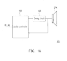
- FIG. 1A illustrates a sound producing system according to an exemplary embodiment of the present application.
- the sound producing system 101 includes an audio controller 102, a driving circuit 103 and a speaker SPK.
- the speaker SPK is used for producing an audible sound.
- the driving circuit 103 is coupled to the speaker SPK and provides a signal for driving the speaker SPK.
- the audio controller 102 is coupled to the speaker SPK and the driving circuit 103.
- the audio controller 102 is configured to receive and process an input audio signal IN_AU, and generate and convert an output audio signal to a driving voltage.
- the driving circuit 103 provides the driving voltage to the speaker SPK for driving the speaker SPK.
- the audio controller 102 receive an amplify gain and pre-amply the input audio signal IN_AU with the amplify gain to obtain a pre-amplified audio signal. Then, the audio controller 102 operates a multiband dynamic range control operation on the pre-amplified audio signal for generating the output audio signal. Furthermore, the audio controller 102 may convert the output audio signal to the driving voltage, and the driving voltage may be transported to the speaker SPK through the driving circuit 103 for driving the speaker SPK.
- the audio controller 102 detects over the driving circuit 103 to obtain at least one excursion parameter of the speaker SPK.
- the audio controller 102 may determine an estimated excursion of the speaker SPK according to the at least one excursion parameter in response to the driving voltage. Also, the audio controller 102 adjusts the amplify gain according to the estimated excursion.
- the audio controller 102 may operate the multiband dynamic range control on the pre-amplified audio signal for generating a compressed audio signal. Then, the audio controller 102 may limit an overall level of the compressed audio signal to a threshold level by applying a limiting gain to the compressed audio signal for limiting the level of the output audio signal and obtaining a limited audio signal as the output audio signal. The limiting gain may also be adjusted according to the estimated excursion of the speaker SPK by the audio controller 102.
- the speaker SPK has at least one diaphragm.
- the diaphragm has a highest response over a resonance frequency.
- the audio controller 102 is operative to operate a first dynamic range control operation over a first frequency band of the pre-amplified audio signal, and the first frequency band is below the resonant frequency.
- the audio controller 102 is operative to operate a second dynamic range control operation over a second frequency band of the pre-amplified audio signal, and the second band is higher than the resonant frequency.
- the compression ratio of the first dynamic range control operation is higher than the compression ratio of the second dynamic range control operation.
- the audio controller 102 is also operative to buffer the pre-amplified audio signal, and filter the buffered pre-amplified audio signal over at least two frequency bands to obtain at least two filtered audio signals each corresponding to one of the at least two frequency bands.
- the audio controller 102 operates at least two separated dynamic range controls over the at least two filtered audio signal respectively to obtain at least two compressed filtered audio signals. Additionally, the audio controller 102 obtains the compressed audio signals by summing the at least two compressed filtered audio signals.
- the audio controller 102 receives a driving current on the driving circuit 103, and generates a first excursion parameter accordingly.
- the driving current is generated in response to the driving voltage applied on the speaker SPK, and the driving current is feedback to the audio controller 102 from the speaker SPK.
- the output audio signal generated by the audio controller 102 may be used to generate a second excursion parameter. That is, the audio controller 102 may determine the estimated excursion of the speaker SPK in response to the driving voltage based on the first excursion parameter and the second excursion parameter.
- the input audio signal IN_AU is transported to the audio controller 102 in continuity.
- the audio controller 102 may delay the input audio signal IN_AU to obtain a first input audio signal for looking ahead. Based on the first input audio signal, an estimated excursion of the speaker SPK in response to the first input audio signal can be determined by the audio controller 102, and whether the first estimated excursion enters a non-linear region of a force factor or stiffness for the speaker SPK can be determined accordingly.
- the audio controller 102 may compensate the first input audio signal to generate a second input audio signal, and the audio controller 102 may pre-amplify the second input audio signal with the amplify gain to obtain the pre-amplified audio signal.
- the audio controller 102 may reduce the amplify gain, and the excursion of the speaker SPK can be controlled to prevent from exceeding the maximum allowable value and to prevent the damage of the speaker SPK,.
- the excursion threshold may be predetermined according to the physical characteristics of the speaker.
- the excursion threshold can also be a predetermined threshold which the audio controller 102 may hard clip or soft clip the output audio signal to prevent the speaker SPK from damage.
- a digital to analog converter and an amplifier may be disposed in the driving circuit 103.
- the digital to analog converter is used to convert the output audio signal to an analog output signal
- the amplifier is used to amplify the analog output audio signal under a bias voltage to obtain the driving voltage.
- the bias voltage may be controlled from the audio controller 102, and the audio controller 102 may detect a signal level of the first input audio signal over a time span, and adjust a level of the bias voltage based on the signal level of the first input audio signal. That is, the signal level of the first input audio signal may be monitored, and when the first input audio signal with small volume is inputted to the audio controller 102, the voltage level of the bias voltage for the amplifier can be reduced, and power consumption can be saved.
- FIG. 1B illustrates a block diagram of another sound producing system 102 according to an exemplary embodiment of the present invention.
- the sound producing system 102 includes an automatic gain controller (AGC) 110, a delay unit 120, a multi-band dynamic range controller (MBDRC) 130, a limiter (not shown), a driving circuit 140 and an excursion controller 150.
- AGC automatic gain controller
- MDRC multi-band dynamic range controller
- the sound producing system 100 is used to drive a speaker SPK.
- the AGC 110 receives an input audio signal IN_AU and an amplify gain UAG, wherein the amplify gain UAG is provided by an application processor according to the setting of a playback application or instruction from an user, and the AGC 110 controls a gain of the input audio signal IN_AU to generate a pre-amplified audio signal CIN_AU according to the amplify gain UAG.
- the delay unit 120 is coupled between an output of the AGC 110 and an input of the MBDRC 130. The delay unit 120 provides a delay time for transporting the pre-amplified audio signal CIN_AU to the input of the MBDRC 130.
- the MBDRC 130 is coupled to the delay unit 120 for receiving the pre-amplified audio signal CIN_AU from the delay unit 120, and the MBDRC 130 operates a multi-band dynamic range control operation on the pre-amplified audio signal CIN_AU to generate an output audio CP_AU.
- a gain limiter may be used to limit the level of the output audio CP_AU.
- the output audio CP_AU is transported to the amplifier 140, and the amplifier 140 amplifying the output audio CP_AU to drive the speaker SPK.
- the excursion controller 150 is coupled between the driving circuit 140 and the AGC 110 to form a feedback circuit.
- the excursion controller 150 receives a voltage signal received by the amplifier 140 to formed a feedback voltage FV, and the excursion controller 150 also receives a current flowing through the speaker SPK to form a feedback current FC.
- the excursion controller 150 generates a first gain control signal GC1 according to the input audio signal IN_AU, the feedback voltage FV and the feedback current FC, and provided the first gain control signal GC1 to the AGC 110 to notify the ACG 110 whether an estimated excursion of the speaker SPK enters a non-linear region of a force factor or stiffness for the speaker.
- the audio controller 102 may compensate the first input audio signal to generate a second input audio signal when the ACG 110 receives the first gain control signal GC1 notifying that the estimated excursion of the speaker SPK enters the non-linear region.
- the MBDRC 130 divides the pre-amplified audio signal CIN_AU into a plurality of parts according to a plurality of different frequency bands.
- the MBDRC 130 respectively operates a plurality of controlling (compressing or expanding) operations on the plurality of parts of the pre-amplified audio signal CIN_AU.
- the controlling operations respectively corresponding to the frequency bands may be different. That is, the different frequency bands of the pre-amplified audio signal CIN_AU can be respectively compressed or expanded by different methods, an optimized audio signal can be obtained.
- the excursion controller 150 calculates the estimated excursion of the speaker SPK according to the feedback voltage FV and the feedback current FC, and the excursion controller 150 generate the first gain control signal GC1 to notify the AGC 110 according to the estimated excursion and the input audio signal. For example, the excursion controller 150 calculates the estimated excursion of the speaker SPK according to the feedback voltage FV and the feedback current FC. For example, the excursion controller 150 calculates the estimated excursion of the speaker SPK by the impedance which is calculated by the feedback voltage FV and the feedback current FC, and obtains the first gain control signal GC1 according to the estimated excursion.
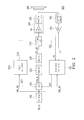
- FIG. 2 illustrates a block diagram of a sound producing system 200 according to another exemplary embodiment of the present invention.
- the sound producing system 200 includes an automatic gain controller (AGC) 210, a delay unit 220, a multi-band dynamic range controller (MBDRC) 230, an amplifier 242, an excursion controller 250, an equalization (EQ) filter 260, a limiting unit 270, a current sensor 280, a digital to analog converter (DAC) 241, an analog to digital converter (ADC) 292, and a signal controller 2110, wherein, the DAC 241 and the amplifier 242 form a driving circuit 240.
- ADC automatic gain controller
- MDRC multi-band dynamic range controller
- EQ equalization
- DAC digital to analog converter
- ADC analog to digital converter
- an input audio signal of music content may be preliminarily processed by the EQ filter 260, and the equalized input audio signal EIN_AU is sent to the AGC 210 for pre-amplifying by the AGC 210 according to an amplify gain.
- the AGC 210 generates the pre-amplified audio signal CIN_AU by amplifying the equalized input audio signal EIN_AU.
- the pre-amplified audio signal CIN_AU is transported to the delay unit 220 and the delay unit 220 provides a delay time for transporting the pre-amplified audio signal CIN_AU to the MBDRC 230.
- the excursion controller 250 is used to calculate the estimated excursion of the diaphragm of the speaker SPK, and the first gain control signal GC1 is generated by the excursion controller 250 according to the estimated excursion.
- FIG. 3 illustrates a diagram of input and output of the MBDRC 230 in FIG. 2 .
- the pre-amplified audio signal CIN_AU may be divided into three parts with different volumes.
- the MBDRC 230 may be an expander to process the input audio which volume is lower than TH1. In a middle volume region, the volume of the output audio may be matched up with the input audio when the volume of the input audio is between TH1 and TH2. In an upper volume region, the volume of the output audio is generated by reducing the volume of the input audio which is larger than TH2.
- FIG. 4 illustrates a block diagram of MBDRC 230 according to the exemplary embodiment of FIG. 2 .
- the MBDRC 230 includes a pre-dynamic range controller 410, band divided filters 4211, 4221 and 4231, dynamic range controllers 4212, 4213, 4222, 4223, 4232 and 4233, a summation unit 430, and a post-dynamic range controller 440.
- the pre-amplified audio signal CIN_AU is processed by the pre-dynamic range controller 410 in first stage, and then the output of the pre-dynamic range controller 410 is transported to the filters 4211, 4221 and 4231 for processing in parallel.
- the filters 4211, 4221 and 4231 are respectively a low pass filter, a band pass filter and a high pass filter. That is, the passing bands of the filters 4211, 4221 and 4231 respectively are different.
- the filter 4231 filtered out the low frequency part of the pre-amplified audio signal CIN_AU, and the low frequency part of the pre-amplified audio signal CIN_AU is transported to the dynamic range controllers 4232 and 4233 in sequence for controlling.
- the filter 4221 filtered out the middle frequency part of the pre-amplified audio signal CIN_AU, and the middle frequency part of the pre-amplified audio signal CIN_AU is transported to the dynamic range controllers 4222 and 4223 in sequence for controlling.
- the filter 4211 filtered out the high frequency part of the pre-amplified audio signal CIN_AU, and the high frequency part of the pre-amplified audio signal CIN_AU is transported to the dynamic range controllers 4212 and 4213 in sequence for controlling.
- All of the outputs of the dynamic range controllers 4213, 4223 and 4233 are transported to the summation unit 430 for a summing operation.
- a result of the summing operation is transported to the post-dynamic range controllers 440 for controlling to generate the output audio CP_AU.
- this control process dynamically alters the compression or expansion ratio and corresponding make-up gain based on the characteristic of each band.
- this apparatus By using this apparatus, it enhances and emphasizes the detail of the music content.
- the sound quality can be further improved by using expanders to depress the small hiss noise in high band, which is perceptually impossible.
- FIG. 5 illustrates a vibrating characteristic of the speaker according to an exemplary embodiment of the present invention.
- the vibrating characteristic of a speaker may be divided according to the frequency bands of the input audio.
- the low band LB whose frequency is lower than the 1st resonant frequency RF1 of the speaker SPK; a mid-band MB whose frequency is above the 1st resonant frequency RF1 but below a second frequency RF2 (7kHz for example); and high band HB whose frequency is above the second frequency RF2.
- the excursion of the speaker SPK is inherently high so that an aggressive compression ratio is applied.
- the excursion of the speaker SPK is limited to be lower than a maximum possible excursion EMAX of the speaker SPK.
- EMAX maximum possible excursion of the speaker SPK.
- the mid-band MB a low compression ratio is applied because the excursion of the speaker SPK has large headroom.
- an expander is used to depress the small signal. The quality perceptually of the audio form the speaker SPK can be optimized.
- MDRC 230 is designed for each one of a plurality of bands. For middle volume, it is processed by applying a related slow attack time and release time to avoid pumping effect. As for the large volume, it is processed by applying a fast attack time and release time to depress an instant peak of a signal.
- the current sensor 280 is coupled between the speaker SPK and the excursion controller 250.
- the current sensor 280 senses a current flowing through the speaker SPK to generate the feedback current FC and transports the feedback current FC to the excursion controller 250.
- the ADC 292 is coupled to the current sensor 280, and the ADC 292 transport the feedback current FC from analog format to digital format.
- the excursion controller 250 receives the feedback current FC in digital format.
- the limiting unit 270 is coupled to output of the MBDRC 230, and used for limiting a gain of the output audio CP_AU according to a second gain control signal GC2.
- the second gain control signal GC2 is generated by the excursion controller 250.
- the excursion controller 250 can generate and transmit the second gain control signal GC2 to the limiting unit 270, so that the audio controller 200 can reduce the amplify gain once the limiting unit 270 receive the second gain control signal GC2.
- the DAC 291 is coupled between the limiting unit 270 and the amplifier 240.
- the DAC 291 is used to convert the output of the limiting unit 270 from digital format to analog format.
- the signal controller 2110 is coupled to the AGC 210, EQ filter 260 and the limiting unit 270.
- the signal controller 2110 receives the equalized input audio EIN_AU and provides a third gain control signal GC3 to the AGC 210 and a fourth gain control signal GC4 to the limiting unit 270.
- the signal controller 2110 decides the estimated excursion to enter the non-linear region by analyzing the equalized input audio EIN_AU through a look ahead analyzing scheme, the signal controller 2110 transports the third gain control signal GC3 to the AGC 210.
- the AGC 210 may compensate the equalized input audio EIN_AU according to the third gain control signal GC3.
- the signal controller 2110 decides the estimated excursion to enter an excursion threshold region by analyzing the equalized input audio EIN_AU through the look ahead analyzing scheme
- the signal controller 2110 transports the fourth gain control signal GC4 to the limiting unit 270.
- the limiting unit 270 may limit a gain of the output audio CP_AU according to the fourth gain control signal GC4.
- the AGC 210 may receive the first and third gain control signals GC1 and GC3 for the gain controlling operation simultaneously, and the limiting unit 270 may receive the second and fourth gain control signals GC2 and GC4 for the gain limiting operation simultaneously.
- FIG. 6A illustrates a control apparatus for a speaker system.
- the structure for a control apparatus 601 as shown in FIG. 6A includes a compensation unit 61, a gain unit 63, and a feedback unit 65.
- an input audio signal (or called a first audio signal) Sa1 is to be amplified by an amplifier AMP and then to be reproduced by the speaker SPK.
- the compensation unit 61 includes an excursion prediction device 611 for excursion calculation, a non-linear compensator 613, and a buffer 615.
- the compensation unit 61 performs look-ahead based compensation.
- the first audio signal Sa1 e.g., in the form of a digital signal, is looked ahead, for example, by using the buffer 615.
- the first audio signal Sa1 may need to be conditioned or can be default as a conditioned signal, or a signal conditioning circuit stage can be optionally included in the control apparatus 601 for generating the conditioned signal for processing of the following stages.
- the first audio signal Sa1 can be regarded as a conditioned signal in the embodiment.
- the excursion prediction device 611 predicts or evaluates the corresponding excursion of the first audio signal Sa1 through a first model for the speaker SPK to generate a predicted excursion of the first audio signal.
- the non-linear compensator 613 determines whether compensation is needed according to the delayed first audio signal from the buffer 615 and the predicted excursion outputted from the excursion prediction device 611.
- the non-linear compensator 613 generates a second audio signal Sa2 by compensation according to the first model and the first detected parameter (denoted by PF1), the value Gc from the gain control unit 63, and the delayed first audio signal Sa1. If compensation for the first audio signal Sa1 is not needed, the non-linear compensator 613 outputs the first audio signal as the second audio signal Sa2 (or may be outputted through a scaling).
- the non-linear compensator 613 may adopt one or more physical parameters of the speaker SPK so as to determine whether the predicted first parameter (such as excursion) enters a non-linear region of the physical parameter.
- the gain unit 63 includes a gain control device 631 and a digital-to-analog converter (DAC) 633.
- the gain control device 631 In response to the second audio signal Sa2 and at least one detected parameter (such as the first detected parameter PF1 and/or second detected parameter PF2 and so on), the gain control device 631 outputs an output audio signal.
- the output audio signal may be converted by the DAC 633 so as to output a third audio signal Sa3 for the amplifier AMP.
- the gain control device 631 outputs a parameter, such as a value Gc indicating the gain value currently used in the gain unit 63, to the non-linear compensator 613 in order for the non-linear compensator 613 to adjust the non-linear compensation according to the current gain value.
- the feedback unit 65 is employed to generate at least one detected parameter according to a feedback signal Sfb indicating such as a feedback current signal Sfb1 and a feedback voltage signal Sfb2 from the speaker SPK.
- the feedback unit 65 includes an excursion control device (or called an excursion detection device) 651, a temperature detection device (or called a temperature detection device) 653, and an analog-to-digital converter (ADC) 655.
- the feedback current Sfb1 and the feedback voltage Sfb2 are evaluated through the temperature detection device 651 and the excursion detection device 651, respectively, so as to generate a first detected parameter PF1 (e.g., the detected excursion of the speaker) and a second detected parameter PF2 (e.g., the temperature of the speaker).
- the gain control device 631 adjusts its gain value.
- the first detected parameter PF1 i.e., the detected excursion
- the first detected parameter PF1 generated by the excursion detection device 651 is adaptively fed back to the non-linear compensator 613.
- FIG. 6B illustrates a sound producing system 602 according to another embodiment of present application.
- the sound producing system 602 is obtained by verifying the control apparatus 601 in FIG. 6A .
- a signal controller 617 is disposed in the compensation unit 61, and an AGC 6311, a delay unit 6312, a MBDRC 6313 and a limiting unit 6314 are disposed in the gain control unit 631.
- the operation about the signal controller 617, AGC 6311, a delay unit 6312, a MBDRC 6313 and a limiting unit 6314 can be referred to the embodiment in FIG. 2 . It can be realized that, a MBDRC operation may be used in the gain controller device 631, and the quality of the sound broadcasted by the speaker SPK can be promoted.
- FIG. 7 illustrates a flow chart for a sound producing method according to an exemplary embodiment of the present invention.
- step S710 an input audio signal is received and pre-amplified with an amplify gain to obtain a pre-amplified audio signal.
- step S720 a multiband dynamic range control is operated on the pre-amplified audio signal to obtain an output audio signal.
- step S730 the output audio signal is converted to a driving voltage, and the driving voltage is provided to a speaker through the driving circuit in step S740.
- step S750 at least one excursion parameter is detected over the driving circuit to obtain to determine an estimated excursion of the speaker in response to the driving voltage, and the amplify gain may be adjusted according to the estimated excursion in step S760.
- a MDRC integrated current and voltage sensing control method and the corresponding control apparatus are provided.
- the input audio can be processed according to different frequency bands, and a performance of the output audio form the speaker can be optimized.
Landscapes
- Circuit For Audible Band Transducer (AREA)
Abstract
Description
- This application is a continuation-in-part application of and claims the priority benefit of a prior application Ser. No.
13/752,375, filed on January 28, 2013 13/752,375 US Provisional application serial no. 61/615,904, filed on March 27, 2012 U.S. provisional application serial no. 61/932,261, filed on January 28, 2014 - The invention relates to a sound producing system and a method thereof. Particularly, the invention relates to the sound producing system with multi-band dynamic range control operation.
- In conventional sound producing system, a gain of the amplifying apparatus is automatic controlled according to the excursion of the speaker. In the opinion of the audio and the excursion, a content of the audio includes a first resonance frequency audio from the speaker. A loudness of the first resonance frequency audio is limited by an excursion of the diaphragm of the speaker and the sense of hearing of human. Such as that, in digital space, a range of the gain for amplifying the audio is limited, and the improvement space for low frequency band of the audio is limited, too.
- The invention is directed to sound producing systems and method thereof, and the sound quality and loudness, especially in audible bass bands are optimized accordingly.
- The invention provides one sound producing system including a speaker, a driving circuit and an audio controller. The speaker is used for producing an audible sound. The driving circuit is connected to the speaker. The audio controller is connected to the speaker through the driving circuit. The audio controller is configured to receive an input audio signal and pre-amplify the input audio signal with an amplify gain to obtain a pre-amplified audio signal; operate a multiband dynamic range control on the pre-amplified audio signal to obtain an output audio signal; convert the output audio signal to a driving voltage; provide the driving voltage to the speaker through the driving circuit; detect over the driving circuit to obtain at least one excursion parameter to determine an estimated excursion of the speaker in response to the driving voltage; and adjust the amplify gain according to the estimated excursion.
- The invention provides another sound producing system including an automatic gain controller, a delay unit, a multi-band dynamic range controller (MBDRC), and an excursion controller. The automatic gain controller receives an input audio signal and an amplify gain and controls the amplify gain of the input audio signal to generate a pre-amplified audio signal according to the input audio signal and the amplify gain. The delay unit is coupled to the automatic gain controller and provides a delay time for transporting the pre-amplified audio signal. The MBDRC is coupled to the delay unit for receiving the pre-amplified audio signal and operates a multi-band dynamic range control operation on the pre-amplified audio signal to generate an output audio signal. The driving circuit is coupled between the multi-band dynamic range controller and the speaker, and the driving circuit receives and amplifies the output audio signal for driving the speaker. The excursion controller is coupled to the driving circuit for receiving a feedback voltage and a feedback current applied on the speaker, wherein the excursion controller determine the amplify gain according to the input audio signal, the feedback voltage and the feedback current.
- The invention also provides a sound producing method including: receiving an input audio signal and pre-amplify the input audio signal with an amplify gain to obtain a pre-amplified audio signal; operating a multiband dynamic range control on the pre-amplified audio signal to obtain an output audio signal; converting the output audio signal to a driving voltage; providing the driving voltage to a speaker through the driving circuit; detecting over the driving circuit to obtain at least one excursion parameter to determine an estimated excursion of the speaker in response to the driving voltage; and adjusting the amplify gain according to the estimated excursion.
- According to the above descriptions, in the invention, the estimated excursion of the speaker is obtained by the feedback current and the feedback voltage. The amplify gain is determined according to the estimated excursion of the speaker (as well as the signal controller). Furthermore, the MBDRAC operation is provided in the sound producing system and the sound producing system. That is, the input audio signal can be controlled by different frequency bands of the input audio, and the sound quality and loudness based on the speaker's (such as micro-speaker) ability can be improved.
- In order to make the aforementioned and other features and advantages of the invention comprehensible, several exemplary embodiments accompanied with figures are described in detail below.
- The accompanying drawings are included to provide a further understanding of the invention, and are incorporated in and constitute a part of this specification. The drawings illustrate embodiments of the invention and, together with the description, serve to explain the principles of the invention.
-
FIG. 1A illustrates a sound producing system according to an exemplary embodiment of the present application. -
FIG. 1B illustrates a block diagram of anothersound producing system 102 according to an exemplary embodiment of the present invention. -
FIG. 2 illustrates a block diagram of anothersound producing system 200 according to another exemplary embodiment of the present invention. -
FIG. 3 illustrates a diagram of input and output of the MBDRC 230 inFIG. 2 . -
FIG. 4 illustrates a block diagram of MBDRC 230 according to the exemplary embodiment ofFIG. 2 . -
FIG. 5 illustrates a vibrating characteristic of the speaker according to an exemplary embodiment of the present invention. -
FIG. 6A illustrates a control apparatus for a speaker system. -
FIG. 6B illustrates asound producing system 602 according to another embodiment of present application. -
FIG. 7 illustrates a flow chart for a sound producing method according to an exemplary embodiment of the present invention. - Referring to
FIG. 1A, FIG. 1A illustrates a sound producing system according to an exemplary embodiment of the present application. Thesound producing system 101 includes anaudio controller 102, adriving circuit 103 and a speaker SPK. The speaker SPK is used for producing an audible sound. Thedriving circuit 103 is coupled to the speaker SPK and provides a signal for driving the speaker SPK. Theaudio controller 102 is coupled to the speaker SPK and thedriving circuit 103. Theaudio controller 102 is configured to receive and process an input audio signal IN_AU, and generate and convert an output audio signal to a driving voltage. Thedriving circuit 103 provides the driving voltage to the speaker SPK for driving the speaker SPK. - In detail, the
audio controller 102 receive an amplify gain and pre-amply the input audio signal IN_AU with the amplify gain to obtain a pre-amplified audio signal. Then, theaudio controller 102 operates a multiband dynamic range control operation on the pre-amplified audio signal for generating the output audio signal. Furthermore, theaudio controller 102 may convert the output audio signal to the driving voltage, and the driving voltage may be transported to the speaker SPK through thedriving circuit 103 for driving the speaker SPK. - On the other hand, the
audio controller 102 detects over the drivingcircuit 103 to obtain at least one excursion parameter of the speaker SPK. Theaudio controller 102 may determine an estimated excursion of the speaker SPK according to the at least one excursion parameter in response to the driving voltage. Also, theaudio controller 102 adjusts the amplify gain according to the estimated excursion. - Please note here, the
audio controller 102 may operate the multiband dynamic range control on the pre-amplified audio signal for generating a compressed audio signal. Then, theaudio controller 102 may limit an overall level of the compressed audio signal to a threshold level by applying a limiting gain to the compressed audio signal for limiting the level of the output audio signal and obtaining a limited audio signal as the output audio signal. The limiting gain may also be adjusted according to the estimated excursion of the speaker SPK by theaudio controller 102. - The speaker SPK has at least one diaphragm. The diaphragm has a highest response over a resonance frequency. In response thereto, the
audio controller 102 is operative to operate a first dynamic range control operation over a first frequency band of the pre-amplified audio signal, and the first frequency band is below the resonant frequency. Moreover, theaudio controller 102 is operative to operate a second dynamic range control operation over a second frequency band of the pre-amplified audio signal, and the second band is higher than the resonant frequency. Especially, the compression ratio of the first dynamic range control operation is higher than the compression ratio of the second dynamic range control operation. - The
audio controller 102 is also operative to buffer the pre-amplified audio signal, and filter the buffered pre-amplified audio signal over at least two frequency bands to obtain at least two filtered audio signals each corresponding to one of the at least two frequency bands. Theaudio controller 102 operates at least two separated dynamic range controls over the at least two filtered audio signal respectively to obtain at least two compressed filtered audio signals. Additionally, theaudio controller 102 obtains the compressed audio signals by summing the at least two compressed filtered audio signals. - About the estimated excursion, the
audio controller 102 receives a driving current on thedriving circuit 103, and generates a first excursion parameter accordingly. Wherein, the driving current is generated in response to the driving voltage applied on the speaker SPK, and the driving current is feedback to theaudio controller 102 from the speaker SPK. On the other hand, the output audio signal generated by theaudio controller 102 may be used to generate a second excursion parameter. That is, theaudio controller 102 may determine the estimated excursion of the speaker SPK in response to the driving voltage based on the first excursion parameter and the second excursion parameter. - In the operation, the input audio signal IN_AU is transported to the
audio controller 102 in continuity. Theaudio controller 102 may delay the input audio signal IN_AU to obtain a first input audio signal for looking ahead. Based on the first input audio signal, an estimated excursion of the speaker SPK in response to the first input audio signal can be determined by theaudio controller 102, and whether the first estimated excursion enters a non-linear region of a force factor or stiffness for the speaker SPK can be determined accordingly. When the estimated excursion enters the non-linear region, theaudio controller 102 may compensate the first input audio signal to generate a second input audio signal, and theaudio controller 102 may pre-amplify the second input audio signal with the amplify gain to obtain the pre-amplified audio signal. Besides, based on the estimated excursion of the speaker SPK in response to the first input audio signal, whether the excursion of the speaker SPK exceeds a maximum allowable value can be determined accordingly. When the estimated excursion of the speaker SPK exceeds an excursion threshold, wherein the excursion threshold is corresponding to the value of the estimated excursion when theaudio controller 102 may assume the excursion of the speaker SPK has exceeded the maximum allowable excursion, theaudio controller 102 may reduce the amplify gain, and the excursion of the speaker SPK can be controlled to prevent from exceeding the maximum allowable value and to prevent the damage of the speaker SPK,. The excursion threshold may be predetermined according to the physical characteristics of the speaker. The excursion threshold can also be a predetermined threshold which theaudio controller 102 may hard clip or soft clip the output audio signal to prevent the speaker SPK from damage. - About the driving
circuit 103, a digital to analog converter and an amplifier may be disposed in thedriving circuit 103. The digital to analog converter is used to convert the output audio signal to an analog output signal, and the amplifier is used to amplify the analog output audio signal under a bias voltage to obtain the driving voltage. The bias voltage may be controlled from theaudio controller 102, and theaudio controller 102 may detect a signal level of the first input audio signal over a time span, and adjust a level of the bias voltage based on the signal level of the first input audio signal. That is, the signal level of the first input audio signal may be monitored, and when the first input audio signal with small volume is inputted to theaudio controller 102, the voltage level of the bias voltage for the amplifier can be reduced, and power consumption can be saved. - Referring to
FIG. 1B, FIG. 1B illustrates a block diagram of anothersound producing system 102 according to an exemplary embodiment of the present invention. Thesound producing system 102 includes an automatic gain controller (AGC) 110, adelay unit 120, a multi-band dynamic range controller (MBDRC) 130, a limiter (not shown), a drivingcircuit 140 and anexcursion controller 150. The sound producing system 100 is used to drive a speaker SPK. - The
AGC 110 receives an input audio signal IN_AU and an amplify gain UAG, wherein the amplify gain UAG is provided by an application processor according to the setting of a playback application or instruction from an user, and theAGC 110 controls a gain of the input audio signal IN_AU to generate a pre-amplified audio signal CIN_AU according to the amplify gain UAG. Thedelay unit 120 is coupled between an output of theAGC 110 and an input of theMBDRC 130. Thedelay unit 120 provides a delay time for transporting the pre-amplified audio signal CIN_AU to the input of theMBDRC 130. TheMBDRC 130 is coupled to thedelay unit 120 for receiving the pre-amplified audio signal CIN_AU from thedelay unit 120, and theMBDRC 130 operates a multi-band dynamic range control operation on the pre-amplified audio signal CIN_AU to generate an output audio CP_AU. A gain limiter may be used to limit the level of the output audio CP_AU. InFIG. 1B , the output audio CP_AU is transported to theamplifier 140, and theamplifier 140 amplifying the output audio CP_AU to drive the speaker SPK. - On the other hand, the
excursion controller 150 is coupled between the drivingcircuit 140 and theAGC 110 to form a feedback circuit. Theexcursion controller 150 receives a voltage signal received by theamplifier 140 to formed a feedback voltage FV, and theexcursion controller 150 also receives a current flowing through the speaker SPK to form a feedback current FC. Theexcursion controller 150 generates a first gain control signal GC1 according to the input audio signal IN_AU, the feedback voltage FV and the feedback current FC, and provided the first gain control signal GC1 to theAGC 110 to notify theACG 110 whether an estimated excursion of the speaker SPK enters a non-linear region of a force factor or stiffness for the speaker. Accordingly, theaudio controller 102 may compensate the first input audio signal to generate a second input audio signal when theACG 110 receives the first gain control signal GC1 notifying that the estimated excursion of the speaker SPK enters the non-linear region. - In detail, the
MBDRC 130 divides the pre-amplified audio signal CIN_AU into a plurality of parts according to a plurality of different frequency bands. TheMBDRC 130 respectively operates a plurality of controlling (compressing or expanding) operations on the plurality of parts of the pre-amplified audio signal CIN_AU. The controlling operations respectively corresponding to the frequency bands may be different. That is, the different frequency bands of the pre-amplified audio signal CIN_AU can be respectively compressed or expanded by different methods, an optimized audio signal can be obtained. - It should be noted here, the estimated excursion of the speaker SPK is important in the embodiment. The
excursion controller 150 calculates the estimated excursion of the speaker SPK according to the feedback voltage FV and the feedback current FC, and theexcursion controller 150 generate the first gain control signal GC1 to notify theAGC 110 according to the estimated excursion and the input audio signal. For example, theexcursion controller 150 calculates the estimated excursion of the speaker SPK according to the feedback voltage FV and the feedback current FC. For example, theexcursion controller 150 calculates the estimated excursion of the speaker SPK by the impedance which is calculated by the feedback voltage FV and the feedback current FC, and obtains the first gain control signal GC1 according to the estimated excursion. - Referring to
FIG. 2, FIG. 2 illustrates a block diagram of asound producing system 200 according to another exemplary embodiment of the present invention. Thesound producing system 200 includes an automatic gain controller (AGC) 210, adelay unit 220, a multi-band dynamic range controller (MBDRC) 230, anamplifier 242, anexcursion controller 250, an equalization (EQ)filter 260, a limitingunit 270, acurrent sensor 280, a digital to analog converter (DAC) 241, an analog to digital converter (ADC) 292, and asignal controller 2110, wherein, theDAC 241 and theamplifier 242 form adriving circuit 240. - In
FIG. 2 , an input audio signal of music content may be preliminarily processed by theEQ filter 260, and the equalized input audio signal EIN_AU is sent to theAGC 210 for pre-amplifying by theAGC 210 according to an amplify gain. TheAGC 210 generates the pre-amplified audio signal CIN_AU by amplifying the equalized input audio signal EIN_AU. Moreover, the pre-amplified audio signal CIN_AU is transported to thedelay unit 220 and thedelay unit 220 provides a delay time for transporting the pre-amplified audio signal CIN_AU to theMBDRC 230. During a period of the delay time, theexcursion controller 250 is used to calculate the estimated excursion of the diaphragm of the speaker SPK, and the first gain control signal GC1 is generated by theexcursion controller 250 according to the estimated excursion. - The pre-amplified audio signal CIN_AU is transported to the
MBDRC 230 through thedelay unit 220. Referring toFIG. 3, FIG. 3 illustrates a diagram of input and output of theMBDRC 230 inFIG. 2 . InFIG. 3 , the pre-amplified audio signal CIN_AU may be divided into three parts with different volumes. TheMBDRC 230 may be an expander to process the input audio which volume is lower than TH1. In a middle volume region, the volume of the output audio may be matched up with the input audio when the volume of the input audio is between TH1 and TH2. In an upper volume region, the volume of the output audio is generated by reducing the volume of the input audio which is larger than TH2. - In detail, referring to
FIG. 4, FIG. 4 illustrates a block diagram ofMBDRC 230 according to the exemplary embodiment ofFIG. 2 . TheMBDRC 230 includes apre-dynamic range controller 410, band dividedfilters dynamic range controllers summation unit 430, and apost-dynamic range controller 440. InFIG. 4 , the pre-amplified audio signal CIN_AU is processed by thepre-dynamic range controller 410 in first stage, and then the output of thepre-dynamic range controller 410 is transported to thefilters filters filters - The
filter 4231 filtered out the low frequency part of the pre-amplified audio signal CIN_AU, and the low frequency part of the pre-amplified audio signal CIN_AU is transported to thedynamic range controllers filter 4221 filtered out the middle frequency part of the pre-amplified audio signal CIN_AU, and the middle frequency part of the pre-amplified audio signal CIN_AU is transported to thedynamic range controllers filter 4211 filtered out the high frequency part of the pre-amplified audio signal CIN_AU, and the high frequency part of the pre-amplified audio signal CIN_AU is transported to thedynamic range controllers - All of the outputs of the
dynamic range controllers summation unit 430 for a summing operation. A result of the summing operation is transported to thepost-dynamic range controllers 440 for controlling to generate the output audio CP_AU. - In this control process, it dynamically alters the compression or expansion ratio and corresponding make-up gain based on the characteristic of each band. By using this apparatus, it enhances and emphasizes the detail of the music content. In addition, the sound quality can be further improved by using expanders to depress the small hiss noise in high band, which is perceptually awful.
- Referring to
FIG. 5, FIG. 5 illustrates a vibrating characteristic of the speaker according to an exemplary embodiment of the present invention. The vibrating characteristic of a speaker may be divided according to the frequency bands of the input audio. InFIG. 5 , the low band LB whose frequency is lower than the 1st resonant frequency RF1 of the speaker SPK; a mid-band MB whose frequency is above the 1st resonant frequency RF1 but below a second frequency RF2 (7kHz for example); and high band HB whose frequency is above the second frequency RF2. In low band LB, the excursion of the speaker SPK is inherently high so that an aggressive compression ratio is applied. Such as that, the excursion of the speaker SPK is limited to be lower than a maximum possible excursion EMAX of the speaker SPK. As for the mid-band MB, a low compression ratio is applied because the excursion of the speaker SPK has large headroom. For the high band HB, an expander is used to depress the small signal. The quality perceptually of the audio form the speaker SPK can be optimized. - Furthermore, in this apparatus,
MDRC 230 is designed for each one of a plurality of bands. For middle volume, it is processed by applying a related slow attack time and release time to avoid pumping effect. As for the large volume, it is processed by applying a fast attack time and release time to depress an instant peak of a signal. - Referring to
FIG. 2 , thecurrent sensor 280 is coupled between the speaker SPK and theexcursion controller 250. Thecurrent sensor 280 senses a current flowing through the speaker SPK to generate the feedback current FC and transports the feedback current FC to theexcursion controller 250. TheADC 292 is coupled to thecurrent sensor 280, and theADC 292 transport the feedback current FC from analog format to digital format. Theexcursion controller 250 receives the feedback current FC in digital format. - The limiting
unit 270 is coupled to output of theMBDRC 230, and used for limiting a gain of the output audio CP_AU according to a second gain control signal GC2. Wherein, the second gain control signal GC2 is generated by theexcursion controller 250. When the estimated excursion of the speaker SPK exceeds the excursion threshold, theexcursion controller 250 can generate and transmit the second gain control signal GC2 to the limitingunit 270, so that theaudio controller 200 can reduce the amplify gain once the limitingunit 270 receive the second gain control signal GC2. - The DAC 291 is coupled between the limiting
unit 270 and theamplifier 240. The DAC 291 is used to convert the output of the limitingunit 270 from digital format to analog format. - The
signal controller 2110 is coupled to theAGC 210,EQ filter 260 and the limitingunit 270. Thesignal controller 2110 receives the equalized input audio EIN_AU and provides a third gain control signal GC3 to theAGC 210 and a fourth gain control signal GC4 to the limitingunit 270. When thesignal controller 2110 decides the estimated excursion to enter the non-linear region by analyzing the equalized input audio EIN_AU through a look ahead analyzing scheme, thesignal controller 2110 transports the third gain control signal GC3 to theAGC 210. TheAGC 210 may compensate the equalized input audio EIN_AU according to the third gain control signal GC3. On the other hand, when thesignal controller 2110 decides the estimated excursion to enter an excursion threshold region by analyzing the equalized input audio EIN_AU through the look ahead analyzing scheme, thesignal controller 2110 transports the fourth gain control signal GC4 to the limitingunit 270. The limitingunit 270 may limit a gain of the output audio CP_AU according to the fourth gain control signal GC4. InFIG. 2 , theAGC 210 may receive the first and third gain control signals GC1 and GC3 for the gain controlling operation simultaneously, and the limitingunit 270 may receive the second and fourth gain control signals GC2 and GC4 for the gain limiting operation simultaneously. - Referring to
FIG. 6A, FIG. 6A illustrates a control apparatus for a speaker system. The structure for acontrol apparatus 601 as shown inFIG. 6A includes acompensation unit 61, again unit 63, and afeedback unit 65. InFIG. 6A , an input audio signal (or called a first audio signal) Sa1 is to be amplified by an amplifier AMP and then to be reproduced by the speaker SPK. - In
FIG. 6A , thecompensation unit 61 includes anexcursion prediction device 611 for excursion calculation, anon-linear compensator 613, and abuffer 615. In an example, thecompensation unit 61 performs look-ahead based compensation. The first audio signal Sa1, e.g., in the form of a digital signal, is looked ahead, for example, by using thebuffer 615. In practical application, the first audio signal Sa1 may need to be conditioned or can be default as a conditioned signal, or a signal conditioning circuit stage can be optionally included in thecontrol apparatus 601 for generating the conditioned signal for processing of the following stages. For the sake of explanation, the first audio signal Sa1 can be regarded as a conditioned signal in the embodiment. Theexcursion prediction device 611 predicts or evaluates the corresponding excursion of the first audio signal Sa1 through a first model for the speaker SPK to generate a predicted excursion of the first audio signal. Thenon-linear compensator 613 determines whether compensation is needed according to the delayed first audio signal from thebuffer 615 and the predicted excursion outputted from theexcursion prediction device 611. In addition, thenon-linear compensator 613 generates a second audio signal Sa2 by compensation according to the first model and the first detected parameter (denoted by PF1), the value Gc from thegain control unit 63, and the delayed first audio signal Sa1. If compensation for the first audio signal Sa1 is not needed, thenon-linear compensator 613 outputs the first audio signal as the second audio signal Sa2 (or may be outputted through a scaling). - In determination as to whether compensation is needed, the
non-linear compensator 613 may adopt one or more physical parameters of the speaker SPK so as to determine whether the predicted first parameter (such as excursion) enters a non-linear region of the physical parameter. - The
gain unit 63 includes again control device 631 and a digital-to-analog converter (DAC) 633. In response to the second audio signal Sa2 and at least one detected parameter (such as the first detected parameter PF1 and/or second detected parameter PF2 and so on), thegain control device 631 outputs an output audio signal. In one example, the output audio signal may be converted by theDAC 633 so as to output a third audio signal Sa3 for the amplifier AMP. In addition, thegain control device 631 outputs a parameter, such as a value Gc indicating the gain value currently used in thegain unit 63, to thenon-linear compensator 613 in order for thenon-linear compensator 613 to adjust the non-linear compensation according to the current gain value. - The
feedback unit 65 is employed to generate at least one detected parameter according to a feedback signal Sfb indicating such as a feedback current signal Sfb1 and a feedback voltage signal Sfb2 from the speaker SPK. Thefeedback unit 65 includes an excursion control device (or called an excursion detection device) 651, a temperature detection device (or called a temperature detection device) 653, and an analog-to-digital converter (ADC) 655. The feedback current Sfb1 and the feedback voltage Sfb2 are evaluated through thetemperature detection device 651 and theexcursion detection device 651, respectively, so as to generate a first detected parameter PF1 (e.g., the detected excursion of the speaker) and a second detected parameter PF2 (e.g., the temperature of the speaker). According to one or more detected parameters such as PF1 and PF2 and the second audio signal Sa2, thegain control device 631 adjusts its gain value. The first detected parameter PF1 (i.e., the detected excursion) generated by theexcursion detection device 651 is adaptively fed back to thenon-linear compensator 613. - Referring to
FIG. 6A andFIG. 6B , wherein,FIG. 6B illustrates asound producing system 602 according to another embodiment of present application. Thesound producing system 602 is obtained by verifying thecontrol apparatus 601 inFIG. 6A . Difference fromFIG. 6A , inFIG. 6B , asignal controller 617 is disposed in thecompensation unit 61, and anAGC 6311, adelay unit 6312, aMBDRC 6313 and a limitingunit 6314 are disposed in thegain control unit 631. - The operation about the
signal controller 617,AGC 6311, adelay unit 6312, aMBDRC 6313 and a limitingunit 6314 can be referred to the embodiment inFIG. 2 . It can be realized that, a MBDRC operation may be used in thegain controller device 631, and the quality of the sound broadcasted by the speaker SPK can be promoted. - Referring to
FIG. 7, FIG. 7 illustrates a flow chart for a sound producing method according to an exemplary embodiment of the present invention. In the step S710, an input audio signal is received and pre-amplified with an amplify gain to obtain a pre-amplified audio signal. In step S720, a multiband dynamic range control is operated on the pre-amplified audio signal to obtain an output audio signal. Moreover, in step S730, the output audio signal is converted to a driving voltage, and the driving voltage is provided to a speaker through the driving circuit in step S740. - In step S750, at least one excursion parameter is detected over the driving circuit to obtain to determine an estimated excursion of the speaker in response to the driving voltage, and the amplify gain may be adjusted according to the estimated excursion in step S760.
- Operation details of the audio amplifying method of the present embodiment have been described in detail in the aforementioned embodiment with reference of the sound producing system, so that detailed descriptions thereof are not repeated.
- In summary, embodiments of a MDRC integrated current and voltage sensing control method and the corresponding control apparatus are provided. The input audio can be processed according to different frequency bands, and a performance of the output audio form the speaker can be optimized.
- It will be apparent to those skilled in the art that various modifications and variations can be made to the structure of the invention without departing from the scope or spirit of the invention. In view of the foregoing, it is intended that the invention cover modifications and variations of this invention provided they fall within the scope of the following claims and their equivalents.
Claims (15)
- A sound producing system for a portable device, comprising:a speaker, for producing an audible sound;a driving circuit, connecting to the speaker;an audio controller, connecting to the speaker through the driving circuit, configured to:receive an input audio signal and pre-amplify the input audio signal with an amplify gain to obtain a pre-amplified audio signal;operate a multiband dynamic range control on the pre-amplified audio signal to obtain an output audio signal;convert the output audio signal to a driving voltage;provide the driving voltage to the speaker through the driving circuit;detect over the driving circuit to obtain at least one excursion parameter to determine an estimated excursion of the speaker in response to the driving voltage; andadjust the amplify gain according to the estimated excursion.
- The sound producing system as claimed in claim 1, wherein the audio controller further configured to:operate the multiband dynamic range control on the pre-amplified audio signal to generate a compressed audio signal;limit an overall level of the compressed audio signal to a threshold level by adding a limiting gain to the compressed audio signal to obtain a limited audio signal as the output audio signal; andadjust the limiting gain according to estimated excursion of the speaker.
- The sound producing system as claimed in claim 2, wherein the speaker comprises at least one diaphragm, which has a highest impulse response over a resonance frequency, and the audio controller is operative to:operate a first dynamic range control operation over a first frequency band of the pre-amplified audio signal, wherein the first frequency band is below the resonant frequency;operate a second dynamic range control operation over a second frequency band of the pre-amplified audio signal, wherein the second band is higher than the resonant frequency;wherein the compression ratio of the first dynamic range control operation is higher than the compression ratio of the second dynamic range control operation.
- The sound producing system as claimed in claim 2 or 3, wherein the audio controller is operative to:buffer the pre-amplified audio signal;filter the buffered pre-amplified audio signal over at least two frequency bands to obtain at least two filtered audio signals each corresponding to one of the at least two frequency bands;operate separate dynamic range control over the at least two filtered audio signal to obtain at least two compressed filtered audio signals;sum the at least two compressed filtered audio signals to obtain the compressed audio signals.
- The sound producing system as claimed in claim 1 or 2, wherein the audio controller is operative to:feedback a driving current on the driving circuit in response to the driving voltage applied on the speaker to generate a first excursion parameter;feedback the output audio signal to generate a second excursion parameter; anddetermine the estimated excursion of the speaker in response to the driving voltage based on the first excursion parameter and the second excursion parameter.
- The sound producing system as claimed in claim 5, wherein the audio controller calculates an impedance of the speaker according to the first and second excursion parameters, and determined the estimated excursion of the speaker according to the impedance.
- The sound producing system as claimed in claim 1, 2, or 5, wherein the audio controller is operative to:delay the input audio signal to obtain a first input audio signal for looking ahead;determine, based on the first input audio signal, an estimated excursion of the speaker in response to the first input audio signal; anddetermine whether the first estimated excursion enters a non-linear region of a force factor or stiffness for the speaker;compensate the first input audio signal to generate a second input audio signal when the estimated excursion enters the non-linear region; andpre-amplify the second input audio signal with the amplify gain to obtain the pre-amplified audio signal;wherein preferably the audio controller is operative to:reduce the amplify gain when the estimated excursion of the speaker exceeds an excursion threshold.
- The sound producing system as claimed in claim 7, wherein the input audio signal, the pre-amplified audio signal, and the output audio signal are digital signals, and the driving circuit comprises:a digital to analog converter to convert the output audio signal to an analog output signal; andan amplifier for amplify the analog output audio signal under a bias voltage to obtain the driving voltage;wherein the audio controller is operative to:provide the bias voltage to the amplifier;detect a signal level of the first input audio signal over a time span; andadjust a level of the bias voltage based on the signal level of the first input audio signal.
- A sound producing method, comprising:receiving an input audio signal and pre-amplify the input audio signal with an amplify gain to obtain a pre-amplified audio signal;operating a multiband dynamic range control on the pre-amplified audio signal to obtain an output audio signal;converting the output audio signal to a driving voltage;providing the driving voltage to a speaker through the driving circuit;detecting over the driving circuit to obtain at least one excursion parameter to determine an estimated excursion of the speaker in response to the driving voltage; andadjusting the amplify gain according to the estimated excursion.
- The audio amplifying method as claimed in claim 9, wherein the step of operate the multiband dynamic range control on the pre-amplified audio signal to obtain the output audio signal comprises:operating the multiband dynamic range control on the pre-amplified audio signal to generate a compressed audio signal;limiting an overall level of the compressed audio signal to a threshold level by adding a limiting gain to the compressed audio signal to obtain a limited audio signal as the output audio signal; andadjusting the limiting gain according to estimated excursion of the speaker;wherein preferably the speaker comprises at least one diaphragm, which has a highest response over a resonance frequency, and wherein preferably the step of operate the multiband dynamic range control on the pre-amplified audio signal comprises:operating a first dynamic range control operation over a first frequency band of the pre-amplified audio signal, wherein the first frequency band is below the resonant frequency;operating a second dynamic range control operation over a second frequency band of the pre-amplified audio signal, wherein the second band is higher than the resonant frequency;wherein the compression ratio of the first dynamic range control operation is higher than the compression ratio of the second dynamic range control operation.
- The audio amplifying method as claimed in claim 10, wherein the step of operate the multiband dynamic range control on the pre-amplified audio signal to obtain the output audio signal further comprises:buffering the pre-amplified audio signal;filtering the buffered pre-amplified audio signal over at least two frequency bands to obtain at least two filtered audio signals each corresponding to one of the at least two frequency band;operating separate dynamic range control over the at least two filtered audio signal to obtain at least two compressed filtered audio signals; andsumming the at least two compressed filtered audio signals to obtain the compressed audio signals.
- The audio amplifying method as claimed in claim 9 or 10, wherein the step of detecting over the driving circuit to obtain the at least one excursion parameter to determine the estimated excursion of the speaker in response to the driving voltage comprises:feedback a driving current on the driving circuit in response to the driving voltage applied on the speaker to generate a first excursion parameterfeedback the output audio signal to generate a second excursion parameter; anddetermining the estimated excursion of the speaker in response to the driving voltage based on the first excursion parameter and the second excursion parameter.
- The audio amplifying method as claimed in claim 12, wherein the step of determining the estimated excursion of the speaker in response to the driving voltage based on the first excursion parameter and the second excursion parameter comprises:calculating an impedance of the speaker by the first and second excursion parameters; anddetermining the estimated excursion of the speaker according to the impedance.
- The audio amplifying method as claimed in claim 9, 10 or 12, further comprising:delaying the input audio signal to obtain a first input audio signal for looking ahead;determining, based on the first input audio signal, an estimated excursion distortion of the speaker in response to the first input audio signal; anddetermining whether the first estimated excursion entering a non-linear region of a force factor or stiffness for the speaker; andcompensating the first input audio signal to generate a second input audio signal when the estimated excursion enters the non-linear region; andpre-amplifying the second input audio signal with the amplify gain to obtain a pre-amplified audio signal.
- The audio amplifying method as claimed in claim 12 or 13, wherein the input audio signal, the pre-amplified audio signal, and the output audio signal are digital signals, and further comprising:converting the output audio signal to an analog output signal;providing a bias voltage for amplifying the analog output audio signal under the bias voltage to obtain the driving voltage;detecting a signal level of the first input audio signal over a time span; andadjusting a level of a bias voltage based on the signal level of the first input audio signal.
Applications Claiming Priority (2)
| Application Number | Priority Date | Filing Date | Title |
|---|---|---|---|
| US201461932261P | 2014-01-28 | 2014-01-28 | |
| US14/335,954 US9614489B2 (en) | 2012-03-27 | 2014-07-21 | Sound producing system and audio amplifying method thereof |
Publications (2)
| Publication Number | Publication Date |
|---|---|
| EP2899883A1 true EP2899883A1 (en) | 2015-07-29 |
| EP2899883B1 EP2899883B1 (en) | 2016-07-20 |
Family
ID=52589218
Family Applications (1)
| Application Number | Title | Priority Date | Filing Date |
|---|---|---|---|
| EP15152561.5A Active EP2899883B1 (en) | 2014-01-28 | 2015-01-26 | Sound producing system and audio amplifying method thereof |
Country Status (3)
| Country | Link |
|---|---|
| EP (1) | EP2899883B1 (en) |
| CN (1) | CN104811154B (en) |
| TW (1) | TWI543638B (en) |
Cited By (3)
| Publication number | Priority date | Publication date | Assignee | Title |
|---|---|---|---|---|
| US10734959B2 (en) | 2016-12-22 | 2020-08-04 | Sony Corporation | Sound processing device and method to suppress an excessive amplitude |
| CN116055951A (en) * | 2022-07-20 | 2023-05-02 | 荣耀终端有限公司 | Signal processing method and electronic device |
| CN118591424A (en) * | 2022-01-25 | 2024-09-03 | 思睿逻辑国际半导体有限公司 | Detection and prevention of nonlinear deviations in haptic actuators |
Families Citing this family (30)
| Publication number | Priority date | Publication date | Assignee | Title |
|---|---|---|---|---|
| CN105551500B (en) * | 2015-09-29 | 2019-06-11 | 宇龙计算机通信科技(深圳)有限公司 | A kind of audio signal processing method and device |
| US10341770B2 (en) * | 2015-09-30 | 2019-07-02 | Apple Inc. | Encoded audio metadata-based loudness equalization and dynamic equalization during DRC |
| US10021485B2 (en) * | 2015-11-17 | 2018-07-10 | Cirrus Logic, Inc. | Prevention of signal clipping due to decrease in amplifier supply voltage |
| CN105784612B (en) * | 2016-03-07 | 2019-05-14 | 安徽师范大学 | The method for detecting mercury ion by assembling gold nanorods |
| CN105916079B (en) * | 2016-06-07 | 2019-09-13 | 瑞声科技(新加坡)有限公司 | A kind of nonlinear loudspeaker compensation method and device |
| CN106101932A (en) * | 2016-07-11 | 2016-11-09 | 深圳天珑无线科技有限公司 | A kind of loudspeaker audio drive circuit, method and intelligent terminal |
| CN106658310B (en) * | 2016-12-23 | 2019-10-15 | 努比亚技术有限公司 | A kind of loudspeaker and terminal and realize the method that sound plays |
| US10462565B2 (en) * | 2017-01-04 | 2019-10-29 | Samsung Electronics Co., Ltd. | Displacement limiter for loudspeaker mechanical protection |
| CN107071634B (en) * | 2017-03-03 | 2023-11-10 | Gn听力公司 | Signal processing device, method and loudspeaker |
| CN108307012B (en) * | 2018-01-24 | 2021-03-26 | 上海摩软通讯技术有限公司 | Mobile terminal and control system and method of telephone receiver |
| EP3794840B1 (en) | 2018-05-18 | 2023-06-28 | Dolby Laboratories Licensing Corporation | Loudspeaker excursion protection |
| CN110809222B (en) * | 2018-08-06 | 2021-02-12 | 深圳瑞利声学技术股份有限公司 | Multi-section dynamic range control method and system and loudspeaker |
| CN109270352B (en) * | 2018-08-23 | 2021-08-10 | 维沃移动通信有限公司 | Amplitude adjusting method and sound generating device |
| EP3662468B1 (en) | 2018-09-28 | 2020-11-04 | Dolby Laboratories Licensing Corporation | Distortion reducing multi-band compressor with dynamic thresholds based on scene switch analyzer guided distortion audibility model |
| CN109788402B (en) * | 2019-01-31 | 2021-04-13 | 维沃移动通信有限公司 | Audio signal processing method and audio signal processing device |
| CN109889170B (en) * | 2019-02-25 | 2021-06-04 | 珠海格力电器股份有限公司 | Audio signal control method and device |
| EP3726730B1 (en) * | 2019-04-17 | 2021-08-25 | Goodix Technology (HK) Company Limited | Peak current limiter |
| CN113345445B (en) * | 2020-02-14 | 2024-09-24 | 瑞昱半导体股份有限公司 | Audio codec circuit |
| US11032642B1 (en) * | 2020-03-10 | 2021-06-08 | Nuvoton Technology Corporation | Combined frequency response and dynamic range correction for loudspeakers |
| JP7439606B2 (en) * | 2020-03-25 | 2024-02-28 | ヤマハ株式会社 | Audio equipment and audio signal processing method |
| CN111741409A (en) * | 2020-06-12 | 2020-10-02 | 瑞声科技(新加坡)有限公司 | Method for compensating for non-linearity of speaker, speaker apparatus, device, and storage medium |
| WO2021253181A1 (en) * | 2020-06-15 | 2021-12-23 | Texas Instruments Incorporated | Control circuit with overcurrent prediction to drive capacitive load |
| CN113852893B (en) * | 2020-06-28 | 2024-11-05 | 北京小米移动软件有限公司 | Data processing method and device, terminal and storage medium |
| CN114095842A (en) * | 2020-08-25 | 2022-02-25 | 上海艾为电子技术股份有限公司 | Driving device and driving method of loudspeaker and electronic equipment |
| CN112866877B (en) * | 2021-04-01 | 2022-06-17 | 维沃移动通信有限公司 | Speaker control method, speaker control device, electronic apparatus, and storage medium |
| US12159528B2 (en) | 2022-01-25 | 2024-12-03 | Cirrus Logic Inc. | Detection and prevention of non-linear excursion in a haptic actuator |
| CN115550798B (en) * | 2022-10-14 | 2026-02-13 | 歌尔科技有限公司 | Audio signal processing methods, systems, speakers, and storage media |
| CN116668904B (en) * | 2022-12-21 | 2024-04-12 | 荣耀终端有限公司 | Audio circuits and electronics |
| WO2024207478A1 (en) * | 2023-04-07 | 2024-10-10 | 瑞声科技(南京)有限公司 | Loudspeaker displacement protection method and apparatus, and device and storage medium |
| TWI899642B (en) * | 2023-09-18 | 2025-10-01 | 晶豪科技股份有限公司 | Circuit, method for audio signal processing with excursion estimation compensation, and non-transitory storage medium |
Citations (6)
| Publication number | Priority date | Publication date | Assignee | Title |
|---|---|---|---|---|
| WO2001003466A2 (en) * | 1999-07-02 | 2001-01-11 | Koninklijke Philips Electronics N.V. | Loudspeaker protection system having frequency band selective audio power control |
| WO2011115944A1 (en) * | 2010-03-18 | 2011-09-22 | Dolby Laboratories Licensing Corporation | Techniques for distortion reducing multi-band compressor with timbre preservation |
| EP2369852A1 (en) * | 2010-03-17 | 2011-09-28 | Harman International Industries, Incorporated | Audio power management system |
| US20130077795A1 (en) * | 2011-09-28 | 2013-03-28 | Texas Instruments Incorporated | Over-Excursion Protection for Loudspeakers |
| US20130195277A1 (en) * | 2012-01-27 | 2013-08-01 | Govind Kannan | System and method for dynamic range compensation of distortion |
| US20130259245A1 (en) * | 2012-03-27 | 2013-10-03 | Htc Corporation | Control method of sound producing, sound producing apparatus, and portable apparatus |
Family Cites Families (2)
| Publication number | Priority date | Publication date | Assignee | Title |
|---|---|---|---|---|
| JP2003110441A (en) * | 2001-09-26 | 2003-04-11 | Toshiba Microelectronics Corp | Pop sound reduction circuit and audio output amplifier |
| CN102668374B (en) * | 2009-10-09 | 2015-09-09 | Dts(英属维尔京群岛)有限公司 | Adaptive Dynamic Range Enhancement for Audio Recording |
-
2014
- 2014-11-19 TW TW103140052A patent/TWI543638B/en active
- 2014-12-04 CN CN201410729905.2A patent/CN104811154B/en active Active
-
2015
- 2015-01-26 EP EP15152561.5A patent/EP2899883B1/en active Active
Patent Citations (6)
| Publication number | Priority date | Publication date | Assignee | Title |
|---|---|---|---|---|
| WO2001003466A2 (en) * | 1999-07-02 | 2001-01-11 | Koninklijke Philips Electronics N.V. | Loudspeaker protection system having frequency band selective audio power control |
| EP2369852A1 (en) * | 2010-03-17 | 2011-09-28 | Harman International Industries, Incorporated | Audio power management system |
| WO2011115944A1 (en) * | 2010-03-18 | 2011-09-22 | Dolby Laboratories Licensing Corporation | Techniques for distortion reducing multi-band compressor with timbre preservation |
| US20130077795A1 (en) * | 2011-09-28 | 2013-03-28 | Texas Instruments Incorporated | Over-Excursion Protection for Loudspeakers |
| US20130195277A1 (en) * | 2012-01-27 | 2013-08-01 | Govind Kannan | System and method for dynamic range compensation of distortion |
| US20130259245A1 (en) * | 2012-03-27 | 2013-10-03 | Htc Corporation | Control method of sound producing, sound producing apparatus, and portable apparatus |
Cited By (4)
| Publication number | Priority date | Publication date | Assignee | Title |
|---|---|---|---|---|
| US10734959B2 (en) | 2016-12-22 | 2020-08-04 | Sony Corporation | Sound processing device and method to suppress an excessive amplitude |
| CN118591424A (en) * | 2022-01-25 | 2024-09-03 | 思睿逻辑国际半导体有限公司 | Detection and prevention of nonlinear deviations in haptic actuators |
| CN116055951A (en) * | 2022-07-20 | 2023-05-02 | 荣耀终端有限公司 | Signal processing method and electronic device |
| CN116055951B (en) * | 2022-07-20 | 2023-10-20 | 荣耀终端有限公司 | Signal processing method and electronic equipment |
Also Published As
| Publication number | Publication date |
|---|---|
| TW201531112A (en) | 2015-08-01 |
| CN104811154B (en) | 2018-10-19 |
| CN104811154A (en) | 2015-07-29 |
| EP2899883B1 (en) | 2016-07-20 |
| TWI543638B (en) | 2016-07-21 |
Similar Documents
| Publication | Publication Date | Title |
|---|---|---|
| EP2899883B1 (en) | Sound producing system and audio amplifying method thereof | |
| US9614489B2 (en) | Sound producing system and audio amplifying method thereof | |
| US10200000B2 (en) | Handheld electronic apparatus, sound producing system and control method of sound producing thereof | |
| EP3240302A1 (en) | Handheld electronic apparatus, sound producing system and control method of sound producing thereof | |
| EP2645740B1 (en) | Control method and apparatus for a speaker system and mobile apparatus | |
| US8600076B2 (en) | Multiband DRC system and method for controlling the same | |
| JP2011515918A (en) | System and method for reducing power consumption for audio playback | |
| US20140161277A1 (en) | Compressor augmented array processing | |
| US20250392861A1 (en) | Selective acoustic optimization for thermally or power limited speaker systems | |
| CN102812636A (en) | Techniques for Distortion-Reducing Multiband Compressors with Sound Quality Preservation | |
| CN1575042A (en) | Hearing aid and operating method with switching among different directional characteristics | |
| US9473102B2 (en) | Level adjusting circuit, digital sound processor, audio AMP integrated circuit, electronic apparatus and method of automatically adjusting level of audio signal | |
| US9214163B2 (en) | Speech processing apparatus and method | |
| US20260067622A1 (en) | Dynamic control for selective acoustic optimization of thermally or power limited speaker systems | |
| EP3379847B1 (en) | Audio device, speaker device, and audio signal processing method | |
| JP7030470B2 (en) | Signal processing equipment, signal processing methods, and programs | |
| JP6314662B2 (en) | Audio signal processing apparatus and program thereof | |
| JP4803193B2 (en) | Audio signal gain control apparatus and gain control method | |
| KR20110050977A (en) | Gain setting method of multiband DDR system and multiband DDR system using the same | |
| JP7439606B2 (en) | Audio equipment and audio signal processing method | |
| GB2613033A (en) | Controlling slew rate | |
| US9414163B2 (en) | Amplifier capable of controlling cut-off frequency in real time and amplification method for controlling cut-off frequency in real time | |
| KR101760122B1 (en) | Apparatus and method for enhancing averaged sound pressure level of mobile handset | |
| JP2007067868A (en) | Low-pitched sound amplification digital signal processor |
Legal Events
| Date | Code | Title | Description |
|---|---|---|---|
| PUAI | Public reference made under article 153(3) epc to a published international application that has entered the european phase |
Free format text: ORIGINAL CODE: 0009012 |
|
| 17P | Request for examination filed |
Effective date: 20150126 |
|
| AK | Designated contracting states |
Kind code of ref document: A1 Designated state(s): AL AT BE BG CH CY CZ DE DK EE ES FI FR GB GR HR HU IE IS IT LI LT LU LV MC MK MT NL NO PL PT RO RS SE SI SK SM TR |
|
| AX | Request for extension of the european patent |
Extension state: BA ME |
|
| RBV | Designated contracting states (corrected) |
Designated state(s): AL AT BE BG CH CY CZ DE DK EE ES FI FR GB GR HR HU IE IS IT LI LT LU LV MC MK MT NL NO PL PT RO RS SE SI SK SM TR |
|
| GRAP | Despatch of communication of intention to grant a patent |
Free format text: ORIGINAL CODE: EPIDOSNIGR1 |
|
| INTG | Intention to grant announced |
Effective date: 20160407 |
|
| RIN1 | Information on inventor provided before grant (corrected) |
Inventor name: CHENG, CHIH-CHIANG Inventor name: TONG, HANN-SHI Inventor name: LEE, CHUN-MIN |
|
| GRAS | Grant fee paid |
Free format text: ORIGINAL CODE: EPIDOSNIGR3 |
|
| GRAA | (expected) grant |
Free format text: ORIGINAL CODE: 0009210 |
|
| AK | Designated contracting states |
Kind code of ref document: B1 Designated state(s): AL AT BE BG CH CY CZ DE DK EE ES FI FR GB GR HR HU IE IS IT LI LT LU LV MC MK MT NL NO PL PT RO RS SE SI SK SM TR |
|
| REG | Reference to a national code |
Ref country code: GB Ref legal event code: FG4D |
|
| REG | Reference to a national code |
Ref country code: CH Ref legal event code: EP |
|
| REG | Reference to a national code |
Ref country code: IE Ref legal event code: FG4D |
|
| REG | Reference to a national code |
Ref country code: AT Ref legal event code: REF Ref document number: 814800 Country of ref document: AT Kind code of ref document: T Effective date: 20160815 |
|
| REG | Reference to a national code |
Ref country code: DE Ref legal event code: R096 Ref document number: 602015000123 Country of ref document: DE |
|
| REG | Reference to a national code |
Ref country code: NL Ref legal event code: FP |
|
| REG | Reference to a national code |
Ref country code: LT Ref legal event code: MG4D |
|
| REG | Reference to a national code |
Ref country code: AT Ref legal event code: MK05 Ref document number: 814800 Country of ref document: AT Kind code of ref document: T Effective date: 20160720 |
|
| REG | Reference to a national code |
Ref country code: FR Ref legal event code: PLFP Year of fee payment: 3 |
|
| PG25 | Lapsed in a contracting state [announced via postgrant information from national office to epo] |
Ref country code: IT Free format text: LAPSE BECAUSE OF FAILURE TO SUBMIT A TRANSLATION OF THE DESCRIPTION OR TO PAY THE FEE WITHIN THE PRESCRIBED TIME-LIMIT Effective date: 20160720 Ref country code: RS Free format text: LAPSE BECAUSE OF FAILURE TO SUBMIT A TRANSLATION OF THE DESCRIPTION OR TO PAY THE FEE WITHIN THE PRESCRIBED TIME-LIMIT Effective date: 20160720 Ref country code: LT Free format text: LAPSE BECAUSE OF FAILURE TO SUBMIT A TRANSLATION OF THE DESCRIPTION OR TO PAY THE FEE WITHIN THE PRESCRIBED TIME-LIMIT Effective date: 20160720 Ref country code: FI Free format text: LAPSE BECAUSE OF FAILURE TO SUBMIT A TRANSLATION OF THE DESCRIPTION OR TO PAY THE FEE WITHIN THE PRESCRIBED TIME-LIMIT Effective date: 20160720 Ref country code: IS Free format text: LAPSE BECAUSE OF FAILURE TO SUBMIT A TRANSLATION OF THE DESCRIPTION OR TO PAY THE FEE WITHIN THE PRESCRIBED TIME-LIMIT Effective date: 20161120 Ref country code: HR Free format text: LAPSE BECAUSE OF FAILURE TO SUBMIT A TRANSLATION OF THE DESCRIPTION OR TO PAY THE FEE WITHIN THE PRESCRIBED TIME-LIMIT Effective date: 20160720 Ref country code: NO Free format text: LAPSE BECAUSE OF FAILURE TO SUBMIT A TRANSLATION OF THE DESCRIPTION OR TO PAY THE FEE WITHIN THE PRESCRIBED TIME-LIMIT Effective date: 20161020 |
|
| PG25 | Lapsed in a contracting state [announced via postgrant information from national office to epo] |
Ref country code: ES Free format text: LAPSE BECAUSE OF FAILURE TO SUBMIT A TRANSLATION OF THE DESCRIPTION OR TO PAY THE FEE WITHIN THE PRESCRIBED TIME-LIMIT Effective date: 20160720 Ref country code: GR Free format text: LAPSE BECAUSE OF FAILURE TO SUBMIT A TRANSLATION OF THE DESCRIPTION OR TO PAY THE FEE WITHIN THE PRESCRIBED TIME-LIMIT Effective date: 20161021 Ref country code: AT Free format text: LAPSE BECAUSE OF FAILURE TO SUBMIT A TRANSLATION OF THE DESCRIPTION OR TO PAY THE FEE WITHIN THE PRESCRIBED TIME-LIMIT Effective date: 20160720 Ref country code: BE Free format text: LAPSE BECAUSE OF FAILURE TO SUBMIT A TRANSLATION OF THE DESCRIPTION OR TO PAY THE FEE WITHIN THE PRESCRIBED TIME-LIMIT Effective date: 20160720 Ref country code: SE Free format text: LAPSE BECAUSE OF FAILURE TO SUBMIT A TRANSLATION OF THE DESCRIPTION OR TO PAY THE FEE WITHIN THE PRESCRIBED TIME-LIMIT Effective date: 20160720 Ref country code: PT Free format text: LAPSE BECAUSE OF FAILURE TO SUBMIT A TRANSLATION OF THE DESCRIPTION OR TO PAY THE FEE WITHIN THE PRESCRIBED TIME-LIMIT Effective date: 20161121 Ref country code: LV Free format text: LAPSE BECAUSE OF FAILURE TO SUBMIT A TRANSLATION OF THE DESCRIPTION OR TO PAY THE FEE WITHIN THE PRESCRIBED TIME-LIMIT Effective date: 20160720 Ref country code: PL Free format text: LAPSE BECAUSE OF FAILURE TO SUBMIT A TRANSLATION OF THE DESCRIPTION OR TO PAY THE FEE WITHIN THE PRESCRIBED TIME-LIMIT Effective date: 20160720 |
|
| REG | Reference to a national code |
Ref country code: DE Ref legal event code: R097 Ref document number: 602015000123 Country of ref document: DE |
|
| PG25 | Lapsed in a contracting state [announced via postgrant information from national office to epo] |
Ref country code: EE Free format text: LAPSE BECAUSE OF FAILURE TO SUBMIT A TRANSLATION OF THE DESCRIPTION OR TO PAY THE FEE WITHIN THE PRESCRIBED TIME-LIMIT Effective date: 20160720 Ref country code: RO Free format text: LAPSE BECAUSE OF FAILURE TO SUBMIT A TRANSLATION OF THE DESCRIPTION OR TO PAY THE FEE WITHIN THE PRESCRIBED TIME-LIMIT Effective date: 20160720 |
|
| PLBE | No opposition filed within time limit |
Free format text: ORIGINAL CODE: 0009261 |
|
| STAA | Information on the status of an ep patent application or granted ep patent |
Free format text: STATUS: NO OPPOSITION FILED WITHIN TIME LIMIT |
|
| PG25 | Lapsed in a contracting state [announced via postgrant information from national office to epo] |
Ref country code: CZ Free format text: LAPSE BECAUSE OF FAILURE TO SUBMIT A TRANSLATION OF THE DESCRIPTION OR TO PAY THE FEE WITHIN THE PRESCRIBED TIME-LIMIT Effective date: 20160720 Ref country code: BG Free format text: LAPSE BECAUSE OF FAILURE TO SUBMIT A TRANSLATION OF THE DESCRIPTION OR TO PAY THE FEE WITHIN THE PRESCRIBED TIME-LIMIT Effective date: 20161020 Ref country code: SM Free format text: LAPSE BECAUSE OF FAILURE TO SUBMIT A TRANSLATION OF THE DESCRIPTION OR TO PAY THE FEE WITHIN THE PRESCRIBED TIME-LIMIT Effective date: 20160720 Ref country code: DK Free format text: LAPSE BECAUSE OF FAILURE TO SUBMIT A TRANSLATION OF THE DESCRIPTION OR TO PAY THE FEE WITHIN THE PRESCRIBED TIME-LIMIT Effective date: 20160720 Ref country code: SK Free format text: LAPSE BECAUSE OF FAILURE TO SUBMIT A TRANSLATION OF THE DESCRIPTION OR TO PAY THE FEE WITHIN THE PRESCRIBED TIME-LIMIT Effective date: 20160720 |
|
| 26N | No opposition filed |
Effective date: 20170421 |
|
| PG25 | Lapsed in a contracting state [announced via postgrant information from national office to epo] |
Ref country code: SI Free format text: LAPSE BECAUSE OF FAILURE TO SUBMIT A TRANSLATION OF THE DESCRIPTION OR TO PAY THE FEE WITHIN THE PRESCRIBED TIME-LIMIT Effective date: 20160720 |
|
| PG25 | Lapsed in a contracting state [announced via postgrant information from national office to epo] |
Ref country code: MC Free format text: LAPSE BECAUSE OF FAILURE TO SUBMIT A TRANSLATION OF THE DESCRIPTION OR TO PAY THE FEE WITHIN THE PRESCRIBED TIME-LIMIT Effective date: 20160720 |
|
| REG | Reference to a national code |
Ref country code: IE Ref legal event code: MM4A |
|
| PG25 | Lapsed in a contracting state [announced via postgrant information from national office to epo] |
Ref country code: LU Free format text: LAPSE BECAUSE OF NON-PAYMENT OF DUE FEES Effective date: 20170126 |
|
| REG | Reference to a national code |
Ref country code: FR Ref legal event code: PLFP Year of fee payment: 4 |
|
| PG25 | Lapsed in a contracting state [announced via postgrant information from national office to epo] |
Ref country code: IE Free format text: LAPSE BECAUSE OF NON-PAYMENT OF DUE FEES Effective date: 20170126 |
|
| REG | Reference to a national code |
Ref country code: CH Ref legal event code: PL |
|
| PG25 | Lapsed in a contracting state [announced via postgrant information from national office to epo] |
Ref country code: MT Free format text: LAPSE BECAUSE OF NON-PAYMENT OF DUE FEES Effective date: 20170126 |
|
| PG25 | Lapsed in a contracting state [announced via postgrant information from national office to epo] |
Ref country code: AL Free format text: LAPSE BECAUSE OF FAILURE TO SUBMIT A TRANSLATION OF THE DESCRIPTION OR TO PAY THE FEE WITHIN THE PRESCRIBED TIME-LIMIT Effective date: 20160720 |
|
| PG25 | Lapsed in a contracting state [announced via postgrant information from national office to epo] |
Ref country code: LI Free format text: LAPSE BECAUSE OF NON-PAYMENT OF DUE FEES Effective date: 20180131 Ref country code: CH Free format text: LAPSE BECAUSE OF NON-PAYMENT OF DUE FEES Effective date: 20180131 |
|
| PG25 | Lapsed in a contracting state [announced via postgrant information from national office to epo] |
Ref country code: HU Free format text: LAPSE BECAUSE OF FAILURE TO SUBMIT A TRANSLATION OF THE DESCRIPTION OR TO PAY THE FEE WITHIN THE PRESCRIBED TIME-LIMIT; INVALID AB INITIO Effective date: 20150126 |
|
| PG25 | Lapsed in a contracting state [announced via postgrant information from national office to epo] |
Ref country code: CY Free format text: LAPSE BECAUSE OF FAILURE TO SUBMIT A TRANSLATION OF THE DESCRIPTION OR TO PAY THE FEE WITHIN THE PRESCRIBED TIME-LIMIT Effective date: 20160720 |
|
| PG25 | Lapsed in a contracting state [announced via postgrant information from national office to epo] |
Ref country code: MK Free format text: LAPSE BECAUSE OF FAILURE TO SUBMIT A TRANSLATION OF THE DESCRIPTION OR TO PAY THE FEE WITHIN THE PRESCRIBED TIME-LIMIT Effective date: 20160720 |
|
| PG25 | Lapsed in a contracting state [announced via postgrant information from national office to epo] |
Ref country code: TR Free format text: LAPSE BECAUSE OF FAILURE TO SUBMIT A TRANSLATION OF THE DESCRIPTION OR TO PAY THE FEE WITHIN THE PRESCRIBED TIME-LIMIT Effective date: 20160720 |
|
| P01 | Opt-out of the competence of the unified patent court (upc) registered |
Effective date: 20230602 |
|
| PGFP | Annual fee paid to national office [announced via postgrant information from national office to epo] |
Ref country code: NL Payment date: 20241214 Year of fee payment: 11 |
|
| PGFP | Annual fee paid to national office [announced via postgrant information from national office to epo] |
Ref country code: GB Payment date: 20241205 Year of fee payment: 11 |
|
| PGFP | Annual fee paid to national office [announced via postgrant information from national office to epo] |
Ref country code: FR Payment date: 20241209 Year of fee payment: 11 |
|
| PGFP | Annual fee paid to national office [announced via postgrant information from national office to epo] |
Ref country code: DE Payment date: 20241203 Year of fee payment: 11 |