EP2899853A1 - Support element and stator assembly comprising the same - Google Patents
Support element and stator assembly comprising the same Download PDFInfo
- Publication number
- EP2899853A1 EP2899853A1 EP14152324.1A EP14152324A EP2899853A1 EP 2899853 A1 EP2899853 A1 EP 2899853A1 EP 14152324 A EP14152324 A EP 14152324A EP 2899853 A1 EP2899853 A1 EP 2899853A1
- Authority
- EP
- European Patent Office
- Prior art keywords
- stator assembly
- support element
- connection arm
- support structure
- radial
- Prior art date
- Legal status (The legal status is an assumption and is not a legal conclusion. Google has not performed a legal analysis and makes no representation as to the accuracy of the status listed.)
- Granted
Links
Images




Classifications
-
- H—ELECTRICITY
- H02—GENERATION; CONVERSION OR DISTRIBUTION OF ELECTRIC POWER
- H02K—DYNAMO-ELECTRIC MACHINES
- H02K3/00—Details of windings
- H02K3/46—Fastening of windings on the stator or rotor structure
- H02K3/50—Fastening of winding heads, equalising connectors, or connections thereto
-
- H—ELECTRICITY
- H02—GENERATION; CONVERSION OR DISTRIBUTION OF ELECTRIC POWER
- H02K—DYNAMO-ELECTRIC MACHINES
- H02K3/00—Details of windings
- H02K3/46—Fastening of windings on the stator or rotor structure
- H02K3/50—Fastening of winding heads, equalising connectors, or connections thereto
- H02K3/505—Fastening of winding heads, equalising connectors, or connections thereto for large machine windings, e.g. bar windings
-
- H—ELECTRICITY
- H02—GENERATION; CONVERSION OR DISTRIBUTION OF ELECTRIC POWER
- H02K—DYNAMO-ELECTRIC MACHINES
- H02K2203/00—Specific aspects not provided for in the other groups of this subclass relating to the windings
- H02K2203/09—Machines characterised by wiring elements other than wires, e.g. bus rings, for connecting the winding terminations
-
- H—ELECTRICITY
- H02—GENERATION; CONVERSION OR DISTRIBUTION OF ELECTRIC POWER
- H02K—DYNAMO-ELECTRIC MACHINES
- H02K5/00—Casings; Enclosures; Supports
- H02K5/24—Casings; Enclosures; Supports specially adapted for suppression or reduction of noise or vibrations
Definitions
- the present disclosure relates to a stator assembly for an electrical machine, and more in particular relates to a support element utilized within the stator assembly in order to improve its performance.
- State-of-the-art electric energy conversion relies on a three-phase power network with alternating currents (AC) at 50Hz or 60Hz frequency and voltage levels ranging from several hundreds of Volts to hundreds of thousands of Volts.
- AC alternating currents
- the conversion of rotating mechanical energy into electric energy and vice versa is done by generators and by motors, respectively.
- Those rotating machines can be divided into asynchronous and synchronous apparatuses.
- Motors and generators comprise a stator and a rotor.
- the rotor of the machine rotates inside the stator bore of the stator.
- Rotating machines generate the magnetic field typically through rotor pole windings.
- the number of rotor poles and the frequency of the stator magnetic field define the number of revolutions per minutes (rpm) of the rotating machine.
- stator-bars of generators are generally made of a top and a bottom layer.
- the bars of top and bottoms layer are connected to each other by copper pieces called lugs, such to form electrical coils.
- An electrical connection is then needed between the electrical coils and the terminals of the generator, which lead the power to the outside through the generator casing.
- this connection is established by copper bars (of rectangular or round cross-sections) bent around the support structure on its outermost diameter.
- phase bars are specially designed to lead the generated electrical power of the generator into an external grid.
- the connection between the phase bars and the terminals, which lead the power through the generator's casing and are called round connections or phase rings.
- the round connections are generally fixed to the support structure to prevent high vibrations.
- the end winding support structure of the generator is located at the front of the press plates and the outer side of the end winding of the stator bars.
- This support structure is used for the fixation of the stator bars ends, to apply mechanical strength to the end winding and withstand the forces occurring during normal operation and accidental incidents.
- the support usually consists of brackets mounted in axial direction and often of supporting rings to stiffen the structure.
- an important problem is the vibration of round connection arms to the phase lugs.
- the Eigen frequency of these arms often need to be detuned (e.g. no resonance between 100 and 140 Hz for 60 Hz applications) or at least the vibration levels have to be reduced to a minimum.
- thermal expansion which does occur during operation of the machine, should not be blocked.
- Such thermal expansion mainly occurs along the axial direction (usually causing a displacement of the connection arm of about 2 - 3 mm), but also in radial and tangential directions. Therefore a "stiff" solution is not possible.
- the stiff solution hinders the thermal expansion, which increases the stress at the strands close to the lug and considerably increases the danger of cracks in the strand.
- the high stress to the cords/tapes of the stiff support may lead to a loosening of the connection over time, which renders this support useless for reducing the vibrations.
- the stiff support according to the teachings of the prior art entails a high risk of breakage caused by the blocking of the thermal expansion.
- the present disclosure is oriented towards providing the aforementioned needs and towards overcoming the aforementioned difficulties.
- the object of the present invention is to provide a support element as substantially defined in independent claim 12, placed between the support structure and the connection arm.
- the support element allows the thermal expansion while detuning the Eigen-frequency in the arms and reducing the amplitude of the vibrations.
- the support element is such to allow axial, radial and tangential displacement of the round connection arm due to thermal expansion whilst hindering vibrations.
- stator assembly as substantially defined in claim 1, which comprises the support element.
- the stator assembly might comprise a number of support elements disposed along its circumferential development as required by the particular configuration of the machine, in order to ensure the correct functioning of the connection arms and allow the thermal expansion thereof.
- the support element shall be made from glass fibre reinforced insulation material with a lamination direction along the contour.
- the upper vertical part comprises screw-type connection means to the support ring.
- the upper vertical part is thicker than the lower vertical part in order to allow movement caused by vibration between the lower part of the support element and the annular ring.
- the horizontal part of the support element is glued with resin to the lower side of the round connection arm. Additionally, it also may be fixed by cords or tapes around the connection arm and the support element to ensure a very stiff contact therebetween.
- the proposed solution was developed after extensive studies of the winding head and round connection vibration behaviour.
- the invention reduces the vibration amplitudes and therefore the stresses due to vibrations in the affected parts considerably. It is easy to install and comparatively cost efficient.
- stator assembly 1 a prospective view of a stator assembly is shown, generally indicated with the reference number 1.
- the stator assembly 1 part of an electrical machine (not shown) comprises internally a plurality of stator winding bars 4 in which voltage is induced. These bars cooperate together with the rotor (not shown) in the process of energy conversion. In particular, the generated power is made available on external terminals (not shown), which are then connected to a grid to feed.
- the connection established between the stator winding bars 4 and the external terminals is operated by specially designed connection bars, generally referred to as "round connection", of which an arm 3 is indicated in the figure.
- the stator assembly 1 may comprise a plurality of connection arms 3, disposed along its circumferential development, in a number generally depending on the particular type of the generator used.
- the stator assembly 1 comprises six connection arms for each top and bottom layer of the stator bars equally spaced from each other, so twelve arms in total. Six arms each for top and bottom layer are a typical arrangement for three-phase generators with two parallel circuits.
- the stator assembly further comprises a support structure, which in turn comprises an annular ring 2.
- the arrangement of the stator assembly 1 is well known to those skilled in the art, and therefore it won't be disclosed with further details.
- connection arms 3 are often subjected to high vibrations.
- the stator assembly according to the invention comprises a support element 6, positioned between the support structure 2 and the connection arm 3.
- connection arms 3 each one linked to the support structure 2 by a respective support element 6.
- the support structure is generally made of an electrical insulating material to avoid unwanted damaging current flows.
- the support element 6 is made of an electrically insulating material as well.
- the support element 6 is made of a reinforced glass fibre.
- the support element 6 comprises a resilient module configured to allow displacements of the connection arm due to its thermal expansion because of high temperatures, which occur during operation, whilst hindering high vibrations.
- the support element 6 comprises a radial member 61 disposed along axial direction A of the electrical machine and an axial member 62 in turn disposed along a radial direction R.
- the axial member 62 of the support element 6 is connected to the connection arm 3, while the radial member 61 is connected to the annular ring 2.
- figure 2 it is shown the support element 6, object of the present invention, in three different views.
- figure 2A, 2B and 2C show the support element 6 respectively in a lateral, front and perspective view.
- the support element 6 is substantially L-shaped and comprises the radial member 61 and the axial member 62, disposed along respectively radial and axial directions of the electrical machine when mounted on the stator assembly (as shown in preceding figure 1 ). More in particular, the radial member 61 comprises a first portion 611 and a second portion 612, the latter being interposed between the axial member 62 and the first portion 611.
- the first portion 611 is connected to the annular ring (not shown) whilst the second portion 612 is released from it such that the support element 6 has a resilient reaction in response to a rotation of second member 612 about a linear pivot region 8.
- the linear region 8 delimits the first portion 611 (connected to the annular ring by means of a screw-type connection 11 indicated in figure 2B ) from the second region 612 which is released from the same.
- the second portion 612 has a thickness which is smaller than that of the first portion 611 such to define a step in correspondence of the linear region 8, so that second portion 612 has its inner surface that, when mounted on the stator assembly and facing the annular ring, is not in direct contact with it.
- the step has a rounded edge so that three-axial tension states, which could arise during resilient displacements of second portion 612, are avoided.
- the support member 6 comprises a U-shaped junction 9, interposed between the axial member 62 and the radial member 61.
- the U-shaped junction 9 offers an additional pivot region which allows the support element to resiliently react to a displacement of the axial member 62 around a region 12, which is substantially located where a curvature of the junction merges with the axial member 62.
- the second member 612 acting as a resilient module as the first member 611 is attached to the annular ring 2 while the second member is released from it, provides for a resilient reaction to an expansion of the connection arm 3 along the axial direction A, as the connection arm is connected to the axial member 62 and thus forces the second portion 612 of the radial member 61 to rotate about a linear region 8, as previously explained.
- the U-shaped junction 9 acts as a further resilient module as it provides a resilient reaction of the support element 6 caused by the expansion of the connection arm 3 along a radial direction R.
- the axial member 62 can resiliently rotate around a linear region 12 this way allowing a thermal expansion of the connection arm 3 in turn connected to the axial member 62.
- the connection arm 3 is glued to the axial member 62 with a resin or fixed with tapes or cords.
- second portion 612 of radial member 61 has a thickness which is smaller than the first portion 611. So there is no contact between second portion 612 and the support structure, thus avoiding friction which would be caused by high vibrations.
- the support element 6 in operation in a deformed state.
- a possible displacement of the second portion 612 indicated by arrow D1 caused by the expansion of the connection arm (not shown) which forces the axial member 62 to move along the axial direction A and consequently forces the second portion 612 to rotate about a linear region 8 of radial member 61.
- the resilient reaction of second member 612 which is released from the support structure, allows such thermal expansion without leading to breakage of the support element.
- thermal expansions can generally derive from the heating up of stator components. While the stator bars in the active part can expand mainly in axial direction, for the end-winding part expansions along radial and tangential directions can occur as well. Therefore, the thermal expansion experienced by the connection art can also be caused typically by the bars of the stator assembly.
Landscapes
- Engineering & Computer Science (AREA)
- Power Engineering (AREA)
- Insulation, Fastening Of Motor, Generator Windings (AREA)
- Electromagnets (AREA)
Abstract
Description
- The present disclosure relates to a stator assembly for an electrical machine, and more in particular relates to a support element utilized within the stator assembly in order to improve its performance.
- State-of-the-art electric energy conversion relies on a three-phase power network with alternating currents (AC) at 50Hz or 60Hz frequency and voltage levels ranging from several hundreds of Volts to hundreds of thousands of Volts. The conversion of rotating mechanical energy into electric energy and vice versa is done by generators and by motors, respectively. Those rotating machines can be divided into asynchronous and synchronous apparatuses. Motors and generators comprise a stator and a rotor. The rotor of the machine rotates inside the stator bore of the stator. Rotating machines generate the magnetic field typically through rotor pole windings. The number of rotor poles and the frequency of the stator magnetic field define the number of revolutions per minutes (rpm) of the rotating machine.
- As known, the stator-bars of generators are generally made of a top and a bottom layer. The bars of top and bottoms layer are connected to each other by copper pieces called lugs, such to form electrical coils. An electrical connection is then needed between the electrical coils and the terminals of the generator, which lead the power to the outside through the generator casing. For this purpose, this connection is established by copper bars (of rectangular or round cross-sections) bent around the support structure on its outermost diameter.
- Generally, the first and the last bar of a coil of the winding are connected to the terminals. These bars (usually six per layer, equally distributed over the circumference) are called phase bars and
are specially designed to lead the generated electrical power of the generator into an external grid. The connection between the phase bars and the terminals, which lead the power through the generator's casing and are called round connections or phase rings. - They are electrically insulated against each other, and quite sophisticated shapes are required for reaching the phase bars and connecting them to the generator terminals whilst maintaining the required insulation distances.
- The round connections are generally fixed to the support structure to prevent high vibrations.
- The end winding support structure of the generator is located at the front of the press plates and the outer side of the end winding of the stator bars. This support structure is used for the fixation of the stator bars ends, to apply mechanical strength to the end winding and withstand the forces occurring during normal operation and accidental incidents. The support usually consists of brackets mounted in axial direction and often of supporting rings to stiffen the structure.
- The ends of the round connections, which are foreseen to be connected to the phase bars, sometimes cannot be fixed to the supporting structure over a long distance, since the position of the phase bars might be located between the supporting brackets.
- As a result of this, round connection ends have a high risk of vibrations.
- As a consequence, an important problem is the vibration of round connection arms to the phase lugs. The Eigen frequency of these arms often need to be detuned (e.g. no resonance between 100 and 140 Hz for 60 Hz applications) or at least the vibration levels have to be reduced to a minimum.
- Cracks in the strands close to the phase lugs and in the lugs can be found in several generators. These cracks are mostly caused by high vibration levels of the round connections arms. Some round connections arms have Eigen frequencies close to 120 Hz (for 60 Hz applications) or 100 Hz (for 50 Hz applications).
- Up to date, some existing solutions suggest applying a very stiff support between the round connection arm and the support ring with cords or tape together with resin. This solution detunes the Eigen-frequency out of the range of 100 to 140 Hz very well and reduces the amplitude of the vibrations.
- On the other hand thermal expansion, which does occur during operation of the machine, should not be blocked. Such thermal expansion mainly occurs along the axial direction (usually causing a displacement of the connection arm of about 2 - 3 mm), but also in radial and tangential directions. Therefore a "stiff" solution is not possible.
- The stiff solution hinders the thermal expansion, which increases the stress at the strands close to the lug and considerably increases the danger of cracks in the strand. On the other hand, the high stress to the cords/tapes of the stiff support may lead to a loosening of the connection over time, which renders this support useless for reducing the vibrations.
- Generally, the stiff support according to the teachings of the prior art entails a high risk of breakage caused by the blocking of the thermal expansion.
- The present disclosure is oriented towards providing the aforementioned needs and towards overcoming the aforementioned difficulties.
- According to preferred embodiments, the object of the present invention is to provide a support element as substantially defined in
independent claim 12, placed between the support structure and the connection arm. - The support element, as it will be described in details with reference to preferred but not limiting embodiments, allows the thermal expansion while detuning the Eigen-frequency in the arms and reducing the amplitude of the vibrations.
- Said differently, the support element is such to allow axial, radial and tangential displacement of the round connection arm due to thermal expansion whilst hindering vibrations.
- Further object of the present invention is to provide a stator assembly, as substantially defined in
claim 1, which comprises the support element. As it will be appreciated, the stator assembly might comprise a number of support elements disposed along its circumferential development as required by the particular configuration of the machine, in order to ensure the correct functioning of the connection arms and allow the thermal expansion thereof. - Preferably, the support element shall be made from glass fibre reinforced insulation material with a lamination direction along the contour.
- According to an aspect of the invention, the upper vertical part comprises screw-type connection means to the support ring. Advantageously, the upper vertical part is thicker than the lower vertical part in order to allow movement caused by vibration between the lower part of the support element and the annular ring.
- Differently, the horizontal part of the support element is glued with resin to the lower side of the round connection arm. Additionally, it also may be fixed by cords or tapes around the connection arm and the support element to ensure a very stiff contact therebetween.
- The proposed solution was developed after extensive studies of the winding head and round connection vibration behaviour. The invention reduces the vibration amplitudes and therefore the stresses due to vibrations in the affected parts considerably. It is easy to install and comparatively cost efficient.
- The foregoing objects and many of the attendant advantages of this invention will become more readily appreciated as the same becomes better understood by reference to the following detailed description when taken in conjunction with the accompanying drawings, wherein:
-
Fig. 1 is a prospective view of a stator assembly according to the present invention; -
Fig. 2 shows different views of a support element according to the present invention; -
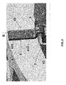
Fig. 3 ,4 and5 show different views of the support element offigure 2 when mounted on a stator assembly; and -
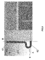
Fig. 6 shows a front view of an example of how the support element can deform in order to allow thermal expansion of the round connection arm in exaggerated scale in order to show the effect. - With reference to
figure 1 , a prospective view of a stator assembly is shown, generally indicated with thereference number 1. Thestator assembly 1, part of an electrical machine (not shown) comprises internally a plurality ofstator winding bars 4 in which voltage is induced. These bars cooperate together with the rotor (not shown) in the process of energy conversion. In particular, the generated power is made available on external terminals (not shown), which are then connected to a grid to feed. The connection established between thestator winding bars 4 and the external terminals is operated by specially designed connection bars, generally referred to as "round connection", of which anarm 3 is indicated in the figure. Thestator assembly 1 may comprise a plurality ofconnection arms 3, disposed along its circumferential development, in a number generally depending on the particular type of the generator used. In the example here described, thestator assembly 1 comprises six connection arms for each top and bottom layer of the stator bars equally spaced from each other, so twelve arms in total. Six arms each for top and bottom layer are a typical arrangement for three-phase generators with two parallel circuits. - The stator assembly further comprises a support structure, which in turn comprises an
annular ring 2. The arrangement of thestator assembly 1 is well known to those skilled in the art, and therefore it won't be disclosed with further details. - As mentioned above,
connection arms 3 are often subjected to high vibrations. In order to hinder the high vibrations, the stator assembly according to the invention comprises asupport element 6, positioned between thesupport structure 2 and theconnection arm 3. - As explained, the figure shows
several connection arms 3 each one linked to thesupport structure 2 by arespective support element 6. It will be appreciated that what will be hereafter described about asingle connection arm 3 and the respective supportingelement 6 will stand for every connection arm and support element of the stator assembly. The support structure is generally made of an electrical insulating material to avoid unwanted damaging current flows. For the same reasons, thesupport element 6 is made of an electrically insulating material as well. Preferably, thesupport element 6 is made of a reinforced glass fibre. Advantageously, thesupport element 6 comprises a resilient module configured to allow displacements of the connection arm due to its thermal expansion because of high temperatures, which occur during operation, whilst hindering high vibrations. - According to a preferred embodiment, the
support element 6 comprises aradial member 61 disposed along axial direction A of the electrical machine and anaxial member 62 in turn disposed along a radial direction R. - The
axial member 62 of thesupport element 6 is connected to theconnection arm 3, while theradial member 61 is connected to theannular ring 2. - Making now reference to
figure 2 , it is shown thesupport element 6, object of the present invention, in three different views. In particular,figure 2A, 2B and 2C show thesupport element 6 respectively in a lateral, front and perspective view. - As clearly shown in the figure, the
support element 6 is substantially L-shaped and comprises theradial member 61 and theaxial member 62, disposed along respectively radial and axial directions of the electrical machine when mounted on the stator assembly (as shown in precedingfigure 1 ). More in particular, theradial member 61 comprises afirst portion 611 and asecond portion 612, the latter being interposed between theaxial member 62 and thefirst portion 611. When mounted on stator assembly, thefirst portion 611 is connected to the annular ring (not shown) whilst thesecond portion 612 is released from it such that thesupport element 6 has a resilient reaction in response to a rotation ofsecond member 612 about alinear pivot region 8. Thelinear region 8 delimits the first portion 611 (connected to the annular ring by means of a screw-type connection 11 indicated infigure 2B ) from thesecond region 612 which is released from the same. - Advantageously, the
second portion 612 has a thickness which is smaller than that of thefirst portion 611 such to define a step in correspondence of thelinear region 8, so thatsecond portion 612 has its inner surface that, when mounted on the stator assembly and facing the annular ring, is not in direct contact with it. This way, friction between the two parts caused by vibration is avoided. Preferably, the step has a rounded edge so that three-axial tension states, which could arise during resilient displacements ofsecond portion 612, are avoided. - Moreover, the
support member 6 comprises aU-shaped junction 9, interposed between theaxial member 62 and theradial member 61. TheU-shaped junction 9 offers an additional pivot region which allows the support element to resiliently react to a displacement of theaxial member 62 around aregion 12, which is substantially located where a curvature of the junction merges with theaxial member 62. - With now reference to following
figures 3-5 , it is shown two different views of thesupport element 6 mounted on the stator assembly. In particular, it is readily understood that thesecond member 612, acting as a resilient module as thefirst member 611 is attached to theannular ring 2 while the second member is released from it, provides for a resilient reaction to an expansion of theconnection arm 3 along the axial direction A, as the connection arm is connected to theaxial member 62 and thus forces thesecond portion 612 of theradial member 61 to rotate about alinear region 8, as previously explained. Similarly, theU-shaped junction 9 acts as a further resilient module as it provides a resilient reaction of thesupport element 6 caused by the expansion of theconnection arm 3 along a radial direction R. In particular, theaxial member 62 can resiliently rotate around alinear region 12 this way allowing a thermal expansion of theconnection arm 3 in turn connected to theaxial member 62. Preferably, theconnection arm 3 is glued to theaxial member 62 with a resin or fixed with tapes or cords. - With particular reference to
figure 5 , it is well visible thatsecond portion 612 ofradial member 61 has a thickness which is smaller than thefirst portion 611. So there is no contact betweensecond portion 612 and the support structure, thus avoiding friction which would be caused by high vibrations. - With reference to last
figure 6 , it is shown thesupport element 6 in operation in a deformed state. In particular, it is shown a possible displacement of thesecond portion 612 indicated by arrow D1 caused by the expansion of the connection arm (not shown) which forces theaxial member 62 to move along the axial direction A and consequently forces thesecond portion 612 to rotate about alinear region 8 ofradial member 61. The resilient reaction ofsecond member 612, which is released from the support structure, allows such thermal expansion without leading to breakage of the support element. - In a similar way, it is shown a possible displacement of the
axial member 62 indicated by arrow D2 caused by the expansion of the connection arm, end-winding and stator bars (not shown) which forces theaxial member 62 to move along the radial direction R and consequently theaxial member 62 to rotate about alinear region 12 which is located where theU-shaped junction 9 merges with theaxial member 62. The resilient reaction of the U-shaped junction allows the thermal expansion of the connection arm along the radial direction without leading to breakage of the support element. - It will be appreciated that thermal expansions can generally derive from the heating up of stator components. While the stator bars in the active part can expand mainly in axial direction, for the end-winding part expansions along radial and tangential directions can occur as well. Therefore, the thermal expansion experienced by the connection art can also be caused typically by the bars of the stator assembly.
- Also given by the arrangement of the bars in the end-winding, there may be a tangential force due to thermal expansion (not shown). The resilient reaction of the U-shaped junction allows the thermal expansion of the connection arm along the tangential direction without leading to breakage of the support element.
- Although the present invention has been fully described in connection with a preferred embodiment, it is evident that modifications may be introduced within the scope thereof, not considering the application to be limited by these embodiments, but by the content of the following claims.
Claims (15)
- Stator assembly (1) for an electrical machine, comprising:• a support structure (2);• a connection arm (3) for connecting one or more stator winding bars (4) to external terminals (5);• a support element (6), placed between said support structure (2) and said connection arm (3),the stator assembly (1) being characterized in that the support element (6) comprises a resilient module (612, 9) configured to allow a thermal expansion of said connection arm (3).
- Stator assembly (1) according to the preceding claim, wherein said support element (6) comprises a radial member (61) disposed along a radial direction of the electrical machine and connected to said support structure (2), and an axial member (62) connected to said connection arm (3) and disposed along an axial direction of the electrical machine.
- Stator assembly (1) according to the preceding claim, wherein the radial member (61) comprises a first portion (611) connected to said support structure (2) and a second portion (612) being interposed between said first portion (611) and said axial member (62) and released from the support structure (2), such to allow an expansion of the connection arm (3) along an axial direction.
- Stator assembly (1) according to the preceding claim, wherein said second portion (612) has a thickness which is smaller of that of said first portion (611) such to define a step therebetween.
- Stator assembly (1) according the any of the claims 2-4, wherein the support element (6) comprises a U-shaped junction (9) interposed between the axial member (62) and the radial member (61) such to allow an expansion of the connection arm (3) along a radial direction.
- Stator assembly (1) according to the preceding claim, wherein said support element (6) and/or said support structure (2) are made of an electrical insulating material.
- Stator assembly (1) according to any of the preceding claims, wherein said support element (6) is made of reinforced glass fibre.
- Stator assembly (1) according to any of the preceding claim, wherein said support element (6) is glued to said connection arm (3).
- Stator assembly (1) according to any of the preceding claims, wherein said support element (6) is connected to the support structure by a screw-type connection (11).
- Stator assembly (1) according to any of the preceding claims, wherein said support structure (2) is an annular support ring (2).
- Electrical machine characterised in that it comprises a stator assembly (1) according to any of the preceding claims.
- Support element (6) for a stator assembly (1) of an electrical machine, configured to be placed between a connection arm (3) and a support structure (2) of the stator assembly (1), the connection arm (3) connecting one or more stator winding bars (4) to external terminals (5), the support element (6) being characterised in that it comprises a resilient module (612, 9).
- The support element (6) according to the preceding claim, comprising a radial member (61) configured to be connected to the support structure (2) and an axial member (62) configured to be connected to the connection arm (3), the radial and axial members (61, 62) disposed respectively along a radial direction and an axial direction of the electrical machine when mounted on the stator assembly (1).
- The support element (6) according to the preceding claim, wherein the radial member (61) comprises a first portion (611) and a second portion (612), the second portion (612) being interposed between said first portion (611) and said axial member (62) and having a thickness which is smaller of that of said first portion (611) such to define a step therebetween.
- The support element (6) according to claims 13 or 14, comprising a U-shaped junction (9) interposed between the axial member (62) and the radial member (61).
Priority Applications (5)
| Application Number | Priority Date | Filing Date | Title |
|---|---|---|---|
| EP14152324.1A EP2899853B1 (en) | 2014-01-23 | 2014-01-23 | Support element and stator assembly comprising the same |
| PCT/EP2014/073792 WO2015110193A1 (en) | 2014-01-23 | 2014-11-05 | Support element and stator assembly comprising the same |
| CN201480073912.XA CN106030995B (en) | 2014-01-23 | 2014-11-05 | Support component and stator module including it |
| JP2016546095A JP6544742B2 (en) | 2014-01-23 | 2014-11-05 | Support element and stator assembly comprising the same |
| US15/214,864 US10355551B2 (en) | 2014-01-23 | 2016-07-20 | Support element and stator assembly comprising the same |
Applications Claiming Priority (1)
| Application Number | Priority Date | Filing Date | Title |
|---|---|---|---|
| EP14152324.1A EP2899853B1 (en) | 2014-01-23 | 2014-01-23 | Support element and stator assembly comprising the same |
Publications (2)
| Publication Number | Publication Date |
|---|---|
| EP2899853A1 true EP2899853A1 (en) | 2015-07-29 |
| EP2899853B1 EP2899853B1 (en) | 2018-10-24 |
Family
ID=49998111
Family Applications (1)
| Application Number | Title | Priority Date | Filing Date |
|---|---|---|---|
| EP14152324.1A Not-in-force EP2899853B1 (en) | 2014-01-23 | 2014-01-23 | Support element and stator assembly comprising the same |
Country Status (5)
| Country | Link |
|---|---|
| US (1) | US10355551B2 (en) |
| EP (1) | EP2899853B1 (en) |
| JP (1) | JP6544742B2 (en) |
| CN (1) | CN106030995B (en) |
| WO (1) | WO2015110193A1 (en) |
Cited By (3)
| Publication number | Priority date | Publication date | Assignee | Title |
|---|---|---|---|---|
| EP3249784A1 (en) * | 2016-05-23 | 2017-11-29 | ABB Schweiz AG | An electric machine |
| US20230163655A1 (en) * | 2020-04-06 | 2023-05-25 | Flender Gmbh | Retaining system for bus bars on stators or stator segments of dynamoelectric machines |
| US20240388146A1 (en) * | 2023-05-16 | 2024-11-21 | Ge Energy Power Conversion Technology Limited | Mounting arrangements |
Families Citing this family (3)
| Publication number | Priority date | Publication date | Assignee | Title |
|---|---|---|---|---|
| CN107134873B (en) * | 2016-02-26 | 2021-02-09 | 博世汽车部件(长沙)有限公司 | Support module and motor |
| DE202016008549U1 (en) * | 2016-11-04 | 2018-07-31 | Nidec Corporation | Busbar unit for an electric motor |
| DE102016225170A1 (en) | 2016-12-15 | 2018-06-21 | Continental Automotive Gmbh | Guide ring for connection to a housing of an electrical machine |
Citations (2)
| Publication number | Priority date | Publication date | Assignee | Title |
|---|---|---|---|---|
| US20120091853A1 (en) * | 2010-10-14 | 2012-04-19 | General Electric Company | Support system for dynamoelectric machine |
| GB2485663A (en) * | 2010-11-19 | 2012-05-23 | Gen Electric | Support system for dynamoelectric machine |
Family Cites Families (15)
| Publication number | Priority date | Publication date | Assignee | Title |
|---|---|---|---|---|
| US1329242A (en) * | 1916-07-11 | 1920-01-27 | Westinghouse Electric & Mfg Co | Coil-supporting device for dynamo-electric machines |
| US3089048A (en) * | 1960-06-03 | 1963-05-07 | Gen Electric | Winding support system for a dynamoelectric machine |
| GB1289826A (en) * | 1968-11-26 | 1972-09-20 | ||
| JPS5260902A (en) * | 1975-11-14 | 1977-05-19 | Hitachi Ltd | Stator in rotary machine |
| US4254352A (en) * | 1979-02-28 | 1981-03-03 | Westinghouse Electric Corp. | Parallel ring and ring extension support system for dynamoelectric machines |
| JPS60186846U (en) * | 1984-05-21 | 1985-12-11 | 三菱電機株式会社 | Stator of rotating electric machine |
| ES2053035T3 (en) * | 1989-09-20 | 1994-07-16 | Asea Brown Boveri | DEVICE FOR FIXING WINDING ENDS OF A STATOR WINDING IN A DYNAMOELECTRIC MACHINE. |
| US5214324A (en) * | 1992-01-03 | 1993-05-25 | General Electric Company | Stator air baffle |
| CN1034376C (en) * | 1993-12-17 | 1997-03-26 | 马渊马达株式会社 | Small electric motor with terminal unit and method for connecting terminal unit |
| DE4421269C1 (en) * | 1994-06-16 | 1995-10-12 | Vem Elektroantriebe Gmbh | Winding head arrangement in stators of surface-cooled AC machines |
| DE19713077B4 (en) * | 1997-03-27 | 2005-08-18 | Siemens Ag | Supporting arrangement for the stator of an electric turbomachine, in particular a turbogenerator |
| JP2000245095A (en) * | 1999-02-19 | 2000-09-08 | Mitsubishi Electric Corp | Turbine generator |
| JP3788386B2 (en) * | 2002-04-18 | 2006-06-21 | 株式会社日立製作所 | Generator |
| US7119462B2 (en) * | 2003-12-17 | 2006-10-10 | Siemens Power Generation, Inc. | Generator rotor conductive path for connecting to a top-turn of a winding |
| ES2644986T3 (en) * | 2011-01-05 | 2017-12-01 | Vestas Wind Systems A/S | Direct Drive Generator |
-
2014
- 2014-01-23 EP EP14152324.1A patent/EP2899853B1/en not_active Not-in-force
- 2014-11-05 CN CN201480073912.XA patent/CN106030995B/en not_active Expired - Fee Related
- 2014-11-05 JP JP2016546095A patent/JP6544742B2/en not_active Expired - Fee Related
- 2014-11-05 WO PCT/EP2014/073792 patent/WO2015110193A1/en not_active Ceased
-
2016
- 2016-07-20 US US15/214,864 patent/US10355551B2/en active Active
Patent Citations (2)
| Publication number | Priority date | Publication date | Assignee | Title |
|---|---|---|---|---|
| US20120091853A1 (en) * | 2010-10-14 | 2012-04-19 | General Electric Company | Support system for dynamoelectric machine |
| GB2485663A (en) * | 2010-11-19 | 2012-05-23 | Gen Electric | Support system for dynamoelectric machine |
Cited By (4)
| Publication number | Priority date | Publication date | Assignee | Title |
|---|---|---|---|---|
| EP3249784A1 (en) * | 2016-05-23 | 2017-11-29 | ABB Schweiz AG | An electric machine |
| US20230163655A1 (en) * | 2020-04-06 | 2023-05-25 | Flender Gmbh | Retaining system for bus bars on stators or stator segments of dynamoelectric machines |
| US12456895B2 (en) * | 2020-04-06 | 2025-10-28 | Flender Gmbh | Retaining system with basic element and fixing elements to fix a bus bar on stator or stator segment of dynamoelectric machine |
| US20240388146A1 (en) * | 2023-05-16 | 2024-11-21 | Ge Energy Power Conversion Technology Limited | Mounting arrangements |
Also Published As
| Publication number | Publication date |
|---|---|
| CN106030995B (en) | 2018-11-20 |
| WO2015110193A1 (en) | 2015-07-30 |
| JP6544742B2 (en) | 2019-07-17 |
| US20160365766A1 (en) | 2016-12-15 |
| EP2899853B1 (en) | 2018-10-24 |
| JP2017511100A (en) | 2017-04-13 |
| CN106030995A (en) | 2016-10-12 |
| US10355551B2 (en) | 2019-07-16 |
Similar Documents
| Publication | Publication Date | Title |
|---|---|---|
| US10355551B2 (en) | Support element and stator assembly comprising the same | |
| CN102684348B (en) | Stator coil segment and electromechanical transducer for electromechanical transducer | |
| BR112017021933B1 (en) | ROTATING DYNAMOELECTRIC MACHINE, WIND POWER GENERATOR, AND WIND POWER INSTALLATION | |
| KR101874115B1 (en) | Support system for dynamoelectric machine | |
| CN111919363B (en) | Combination of an AC motor and a converter unit and wind power plant | |
| US10177621B2 (en) | Rotating electric machine or wind power generation system | |
| US20230163651A1 (en) | Stator provided with insulating paper, motor having stator, and method for manufacturing motor | |
| EP3648313B1 (en) | Rotating electrical machine | |
| JP2019149893A (en) | Stator for rotary electric machine | |
| US20190280550A1 (en) | Laminated stack motor | |
| US11532964B2 (en) | Generator rotor flat wire winding | |
| EP2413478A1 (en) | Phase ring assembly | |
| EP3776812B1 (en) | Winding of an electric machine | |
| US2427282A (en) | Wound armature for electric machines | |
| JP3719850B2 (en) | Rotating machine rotor coil end support device | |
| CN208571766U (en) | A kind of insulating support and motor | |
| JP3360949B2 (en) | Winding rotor coil | |
| EP2858216B1 (en) | Insulating phase separators for electrical machines | |
| JPS63129824A (en) | Armature winding for rotary electric machine | |
| Curiac | Forces and stresses in squirrel cage motors during starting | |
| KR20170001885U (en) | Rotor coil bending protection of the salient pole generator | |
| JP2011024330A (en) | Rotating electrical machine | |
| EP3181609A1 (en) | A support for end windings of an electric machine |
Legal Events
| Date | Code | Title | Description |
|---|---|---|---|
| PUAI | Public reference made under article 153(3) epc to a published international application that has entered the european phase |
Free format text: ORIGINAL CODE: 0009012 |
|
| 17P | Request for examination filed |
Effective date: 20140123 |
|
| AK | Designated contracting states |
Kind code of ref document: A1 Designated state(s): AL AT BE BG CH CY CZ DE DK EE ES FI FR GB GR HR HU IE IS IT LI LT LU LV MC MK MT NL NO PL PT RO RS SE SI SK SM TR |
|
| AX | Request for extension of the european patent |
Extension state: BA ME |
|
| RAP1 | Party data changed (applicant data changed or rights of an application transferred) |
Owner name: GENERAL ELECTRIC TECHNOLOGY GMBH |
|
| GRAP | Despatch of communication of intention to grant a patent |
Free format text: ORIGINAL CODE: EPIDOSNIGR1 |
|
| STAA | Information on the status of an ep patent application or granted ep patent |
Free format text: STATUS: GRANT OF PATENT IS INTENDED |
|
| INTG | Intention to grant announced |
Effective date: 20180806 |
|
| GRAS | Grant fee paid |
Free format text: ORIGINAL CODE: EPIDOSNIGR3 |
|
| GRAA | (expected) grant |
Free format text: ORIGINAL CODE: 0009210 |
|
| STAA | Information on the status of an ep patent application or granted ep patent |
Free format text: STATUS: THE PATENT HAS BEEN GRANTED |
|
| AK | Designated contracting states |
Kind code of ref document: B1 Designated state(s): AL AT BE BG CH CY CZ DE DK EE ES FI FR GB GR HR HU IE IS IT LI LT LU LV MC MK MT NL NO PL PT RO RS SE SI SK SM TR |
|
| REG | Reference to a national code |
Ref country code: CH Ref legal event code: EP |
|
| REG | Reference to a national code |
Ref country code: IE Ref legal event code: FG4D |
|
| REG | Reference to a national code |
Ref country code: AT Ref legal event code: REF Ref document number: 1057835 Country of ref document: AT Kind code of ref document: T Effective date: 20181115 |
|
| REG | Reference to a national code |
Ref country code: DE Ref legal event code: R096 Ref document number: 602014034490 Country of ref document: DE |
|
| REG | Reference to a national code |
Ref country code: NL Ref legal event code: MP Effective date: 20181024 |
|
| REG | Reference to a national code |
Ref country code: LT Ref legal event code: MG4D |
|
| REG | Reference to a national code |
Ref country code: AT Ref legal event code: MK05 Ref document number: 1057835 Country of ref document: AT Kind code of ref document: T Effective date: 20181024 |
|
| PG25 | Lapsed in a contracting state [announced via postgrant information from national office to epo] |
Ref country code: NL Free format text: LAPSE BECAUSE OF FAILURE TO SUBMIT A TRANSLATION OF THE DESCRIPTION OR TO PAY THE FEE WITHIN THE PRESCRIBED TIME-LIMIT Effective date: 20181024 |
|
| PG25 | Lapsed in a contracting state [announced via postgrant information from national office to epo] |
Ref country code: HR Free format text: LAPSE BECAUSE OF FAILURE TO SUBMIT A TRANSLATION OF THE DESCRIPTION OR TO PAY THE FEE WITHIN THE PRESCRIBED TIME-LIMIT Effective date: 20181024 Ref country code: LT Free format text: LAPSE BECAUSE OF FAILURE TO SUBMIT A TRANSLATION OF THE DESCRIPTION OR TO PAY THE FEE WITHIN THE PRESCRIBED TIME-LIMIT Effective date: 20181024 Ref country code: PL Free format text: LAPSE BECAUSE OF FAILURE TO SUBMIT A TRANSLATION OF THE DESCRIPTION OR TO PAY THE FEE WITHIN THE PRESCRIBED TIME-LIMIT Effective date: 20181024 Ref country code: AT Free format text: LAPSE BECAUSE OF FAILURE TO SUBMIT A TRANSLATION OF THE DESCRIPTION OR TO PAY THE FEE WITHIN THE PRESCRIBED TIME-LIMIT Effective date: 20181024 Ref country code: NO Free format text: LAPSE BECAUSE OF FAILURE TO SUBMIT A TRANSLATION OF THE DESCRIPTION OR TO PAY THE FEE WITHIN THE PRESCRIBED TIME-LIMIT Effective date: 20190124 Ref country code: LV Free format text: LAPSE BECAUSE OF FAILURE TO SUBMIT A TRANSLATION OF THE DESCRIPTION OR TO PAY THE FEE WITHIN THE PRESCRIBED TIME-LIMIT Effective date: 20181024 Ref country code: FI Free format text: LAPSE BECAUSE OF FAILURE TO SUBMIT A TRANSLATION OF THE DESCRIPTION OR TO PAY THE FEE WITHIN THE PRESCRIBED TIME-LIMIT Effective date: 20181024 Ref country code: IS Free format text: LAPSE BECAUSE OF FAILURE TO SUBMIT A TRANSLATION OF THE DESCRIPTION OR TO PAY THE FEE WITHIN THE PRESCRIBED TIME-LIMIT Effective date: 20190224 Ref country code: ES Free format text: LAPSE BECAUSE OF FAILURE TO SUBMIT A TRANSLATION OF THE DESCRIPTION OR TO PAY THE FEE WITHIN THE PRESCRIBED TIME-LIMIT Effective date: 20181024 Ref country code: BG Free format text: LAPSE BECAUSE OF FAILURE TO SUBMIT A TRANSLATION OF THE DESCRIPTION OR TO PAY THE FEE WITHIN THE PRESCRIBED TIME-LIMIT Effective date: 20190124 |
|
| PG25 | Lapsed in a contracting state [announced via postgrant information from national office to epo] |
Ref country code: GR Free format text: LAPSE BECAUSE OF FAILURE TO SUBMIT A TRANSLATION OF THE DESCRIPTION OR TO PAY THE FEE WITHIN THE PRESCRIBED TIME-LIMIT Effective date: 20190125 Ref country code: SE Free format text: LAPSE BECAUSE OF FAILURE TO SUBMIT A TRANSLATION OF THE DESCRIPTION OR TO PAY THE FEE WITHIN THE PRESCRIBED TIME-LIMIT Effective date: 20181024 Ref country code: PT Free format text: LAPSE BECAUSE OF FAILURE TO SUBMIT A TRANSLATION OF THE DESCRIPTION OR TO PAY THE FEE WITHIN THE PRESCRIBED TIME-LIMIT Effective date: 20190224 Ref country code: AL Free format text: LAPSE BECAUSE OF FAILURE TO SUBMIT A TRANSLATION OF THE DESCRIPTION OR TO PAY THE FEE WITHIN THE PRESCRIBED TIME-LIMIT Effective date: 20181024 Ref country code: RS Free format text: LAPSE BECAUSE OF FAILURE TO SUBMIT A TRANSLATION OF THE DESCRIPTION OR TO PAY THE FEE WITHIN THE PRESCRIBED TIME-LIMIT Effective date: 20181024 |
|
| REG | Reference to a national code |
Ref country code: DE Ref legal event code: R097 Ref document number: 602014034490 Country of ref document: DE |
|
| PG25 | Lapsed in a contracting state [announced via postgrant information from national office to epo] |
Ref country code: CZ Free format text: LAPSE BECAUSE OF FAILURE TO SUBMIT A TRANSLATION OF THE DESCRIPTION OR TO PAY THE FEE WITHIN THE PRESCRIBED TIME-LIMIT Effective date: 20181024 Ref country code: DK Free format text: LAPSE BECAUSE OF FAILURE TO SUBMIT A TRANSLATION OF THE DESCRIPTION OR TO PAY THE FEE WITHIN THE PRESCRIBED TIME-LIMIT Effective date: 20181024 |
|
| PG25 | Lapsed in a contracting state [announced via postgrant information from national office to epo] |
Ref country code: MC Free format text: LAPSE BECAUSE OF FAILURE TO SUBMIT A TRANSLATION OF THE DESCRIPTION OR TO PAY THE FEE WITHIN THE PRESCRIBED TIME-LIMIT Effective date: 20181024 Ref country code: SM Free format text: LAPSE BECAUSE OF FAILURE TO SUBMIT A TRANSLATION OF THE DESCRIPTION OR TO PAY THE FEE WITHIN THE PRESCRIBED TIME-LIMIT Effective date: 20181024 Ref country code: EE Free format text: LAPSE BECAUSE OF FAILURE TO SUBMIT A TRANSLATION OF THE DESCRIPTION OR TO PAY THE FEE WITHIN THE PRESCRIBED TIME-LIMIT Effective date: 20181024 Ref country code: SK Free format text: LAPSE BECAUSE OF FAILURE TO SUBMIT A TRANSLATION OF THE DESCRIPTION OR TO PAY THE FEE WITHIN THE PRESCRIBED TIME-LIMIT Effective date: 20181024 Ref country code: RO Free format text: LAPSE BECAUSE OF FAILURE TO SUBMIT A TRANSLATION OF THE DESCRIPTION OR TO PAY THE FEE WITHIN THE PRESCRIBED TIME-LIMIT Effective date: 20181024 |
|
| PLBE | No opposition filed within time limit |
Free format text: ORIGINAL CODE: 0009261 |
|
| REG | Reference to a national code |
Ref country code: CH Ref legal event code: PL |
|
| STAA | Information on the status of an ep patent application or granted ep patent |
Free format text: STATUS: NO OPPOSITION FILED WITHIN TIME LIMIT |
|
| GBPC | Gb: european patent ceased through non-payment of renewal fee |
Effective date: 20190124 |
|
| PG25 | Lapsed in a contracting state [announced via postgrant information from national office to epo] |
Ref country code: LU Free format text: LAPSE BECAUSE OF NON-PAYMENT OF DUE FEES Effective date: 20190123 |
|
| 26N | No opposition filed |
Effective date: 20190725 |
|
| REG | Reference to a national code |
Ref country code: BE Ref legal event code: MM Effective date: 20190131 |
|
| REG | Reference to a national code |
Ref country code: IE Ref legal event code: MM4A |
|
| PG25 | Lapsed in a contracting state [announced via postgrant information from national office to epo] |
Ref country code: SI Free format text: LAPSE BECAUSE OF FAILURE TO SUBMIT A TRANSLATION OF THE DESCRIPTION OR TO PAY THE FEE WITHIN THE PRESCRIBED TIME-LIMIT Effective date: 20181024 Ref country code: FR Free format text: LAPSE BECAUSE OF NON-PAYMENT OF DUE FEES Effective date: 20190131 |
|
| PG25 | Lapsed in a contracting state [announced via postgrant information from national office to epo] |
Ref country code: BE Free format text: LAPSE BECAUSE OF NON-PAYMENT OF DUE FEES Effective date: 20190131 |
|
| PG25 | Lapsed in a contracting state [announced via postgrant information from national office to epo] |
Ref country code: CH Free format text: LAPSE BECAUSE OF NON-PAYMENT OF DUE FEES Effective date: 20190131 Ref country code: LI Free format text: LAPSE BECAUSE OF NON-PAYMENT OF DUE FEES Effective date: 20190131 Ref country code: GB Free format text: LAPSE BECAUSE OF NON-PAYMENT OF DUE FEES Effective date: 20190124 |
|
| PG25 | Lapsed in a contracting state [announced via postgrant information from national office to epo] |
Ref country code: IE Free format text: LAPSE BECAUSE OF NON-PAYMENT OF DUE FEES Effective date: 20190123 |
|
| PG25 | Lapsed in a contracting state [announced via postgrant information from national office to epo] |
Ref country code: TR Free format text: LAPSE BECAUSE OF FAILURE TO SUBMIT A TRANSLATION OF THE DESCRIPTION OR TO PAY THE FEE WITHIN THE PRESCRIBED TIME-LIMIT Effective date: 20181024 |
|
| PG25 | Lapsed in a contracting state [announced via postgrant information from national office to epo] |
Ref country code: MT Free format text: LAPSE BECAUSE OF NON-PAYMENT OF DUE FEES Effective date: 20190123 |
|
| PG25 | Lapsed in a contracting state [announced via postgrant information from national office to epo] |
Ref country code: CY Free format text: LAPSE BECAUSE OF FAILURE TO SUBMIT A TRANSLATION OF THE DESCRIPTION OR TO PAY THE FEE WITHIN THE PRESCRIBED TIME-LIMIT Effective date: 20181024 |
|
| PG25 | Lapsed in a contracting state [announced via postgrant information from national office to epo] |
Ref country code: HU Free format text: LAPSE BECAUSE OF FAILURE TO SUBMIT A TRANSLATION OF THE DESCRIPTION OR TO PAY THE FEE WITHIN THE PRESCRIBED TIME-LIMIT; INVALID AB INITIO Effective date: 20140123 |
|
| PGFP | Annual fee paid to national office [announced via postgrant information from national office to epo] |
Ref country code: IT Payment date: 20220103 Year of fee payment: 9 |
|
| PG25 | Lapsed in a contracting state [announced via postgrant information from national office to epo] |
Ref country code: MK Free format text: LAPSE BECAUSE OF FAILURE TO SUBMIT A TRANSLATION OF THE DESCRIPTION OR TO PAY THE FEE WITHIN THE PRESCRIBED TIME-LIMIT Effective date: 20181024 |
|
| PGFP | Annual fee paid to national office [announced via postgrant information from national office to epo] |
Ref country code: DE Payment date: 20221220 Year of fee payment: 10 |
|
| P01 | Opt-out of the competence of the unified patent court (upc) registered |
Effective date: 20230523 |
|
| PG25 | Lapsed in a contracting state [announced via postgrant information from national office to epo] |
Ref country code: IT Free format text: LAPSE BECAUSE OF NON-PAYMENT OF DUE FEES Effective date: 20230123 |
|
| REG | Reference to a national code |
Ref country code: DE Ref legal event code: R119 Ref document number: 602014034490 Country of ref document: DE |
|
| PG25 | Lapsed in a contracting state [announced via postgrant information from national office to epo] |
Ref country code: DE Free format text: LAPSE BECAUSE OF NON-PAYMENT OF DUE FEES Effective date: 20240801 |
|
| PG25 | Lapsed in a contracting state [announced via postgrant information from national office to epo] |
Ref country code: DE Free format text: LAPSE BECAUSE OF NON-PAYMENT OF DUE FEES Effective date: 20240801 |