EP2899774A1 - Battery pack - Google Patents
Battery pack Download PDFInfo
- Publication number
- EP2899774A1 EP2899774A1 EP14191793.0A EP14191793A EP2899774A1 EP 2899774 A1 EP2899774 A1 EP 2899774A1 EP 14191793 A EP14191793 A EP 14191793A EP 2899774 A1 EP2899774 A1 EP 2899774A1
- Authority
- EP
- European Patent Office
- Prior art keywords
- battery
- battery pack
- hole
- holes
- battery cell
- Prior art date
- Legal status (The legal status is an assumption and is not a legal conclusion. Google has not performed a legal analysis and makes no representation as to the accuracy of the status listed.)
- Granted
Links
Images




Classifications
-
- H—ELECTRICITY
- H01—ELECTRIC ELEMENTS
- H01M—PROCESSES OR MEANS, e.g. BATTERIES, FOR THE DIRECT CONVERSION OF CHEMICAL ENERGY INTO ELECTRICAL ENERGY
- H01M50/00—Constructional details or processes of manufacture of the non-active parts of electrochemical cells other than fuel cells, e.g. hybrid cells
- H01M50/20—Mountings; Secondary casings or frames; Racks, modules or packs; Suspension devices; Shock absorbers; Transport or carrying devices; Holders
- H01M50/267—Mountings; Secondary casings or frames; Racks, modules or packs; Suspension devices; Shock absorbers; Transport or carrying devices; Holders having means for adapting to batteries or cells of different types or different sizes
-
- H—ELECTRICITY
- H01—ELECTRIC ELEMENTS
- H01M—PROCESSES OR MEANS, e.g. BATTERIES, FOR THE DIRECT CONVERSION OF CHEMICAL ENERGY INTO ELECTRICAL ENERGY
- H01M50/00—Constructional details or processes of manufacture of the non-active parts of electrochemical cells other than fuel cells, e.g. hybrid cells
- H01M50/10—Primary casings; Jackets or wrappings
- H01M50/102—Primary casings; Jackets or wrappings characterised by their shape or physical structure
- H01M50/103—Primary casings; Jackets or wrappings characterised by their shape or physical structure prismatic or rectangular
-
- B—PERFORMING OPERATIONS; TRANSPORTING
- B25—HAND TOOLS; PORTABLE POWER-DRIVEN TOOLS; MANIPULATORS
- B25F—COMBINATION OR MULTI-PURPOSE TOOLS NOT OTHERWISE PROVIDED FOR; DETAILS OR COMPONENTS OF PORTABLE POWER-DRIVEN TOOLS NOT PARTICULARLY RELATED TO THE OPERATIONS PERFORMED AND NOT OTHERWISE PROVIDED FOR
- B25F5/00—Details or components of portable power-driven tools not particularly related to the operations performed and not otherwise provided for
- B25F5/02—Construction of casings, bodies or handles
-
- H—ELECTRICITY
- H01—ELECTRIC ELEMENTS
- H01M—PROCESSES OR MEANS, e.g. BATTERIES, FOR THE DIRECT CONVERSION OF CHEMICAL ENERGY INTO ELECTRICAL ENERGY
- H01M50/00—Constructional details or processes of manufacture of the non-active parts of electrochemical cells other than fuel cells, e.g. hybrid cells
- H01M50/20—Mountings; Secondary casings or frames; Racks, modules or packs; Suspension devices; Shock absorbers; Transport or carrying devices; Holders
-
- H—ELECTRICITY
- H01—ELECTRIC ELEMENTS
- H01M—PROCESSES OR MEANS, e.g. BATTERIES, FOR THE DIRECT CONVERSION OF CHEMICAL ENERGY INTO ELECTRICAL ENERGY
- H01M50/00—Constructional details or processes of manufacture of the non-active parts of electrochemical cells other than fuel cells, e.g. hybrid cells
- H01M50/20—Mountings; Secondary casings or frames; Racks, modules or packs; Suspension devices; Shock absorbers; Transport or carrying devices; Holders
- H01M50/204—Racks, modules or packs for multiple batteries or multiple cells
- H01M50/207—Racks, modules or packs for multiple batteries or multiple cells characterised by their shape
- H01M50/213—Racks, modules or packs for multiple batteries or multiple cells characterised by their shape adapted for cells having curved cross-section, e.g. round or elliptic
-
- H—ELECTRICITY
- H01—ELECTRIC ELEMENTS
- H01M—PROCESSES OR MEANS, e.g. BATTERIES, FOR THE DIRECT CONVERSION OF CHEMICAL ENERGY INTO ELECTRICAL ENERGY
- H01M2220/00—Batteries for particular applications
- H01M2220/30—Batteries in portable systems, e.g. mobile phone, laptop
-
- Y—GENERAL TAGGING OF NEW TECHNOLOGICAL DEVELOPMENTS; GENERAL TAGGING OF CROSS-SECTIONAL TECHNOLOGIES SPANNING OVER SEVERAL SECTIONS OF THE IPC; TECHNICAL SUBJECTS COVERED BY FORMER USPC CROSS-REFERENCE ART COLLECTIONS [XRACs] AND DIGESTS
- Y02—TECHNOLOGIES OR APPLICATIONS FOR MITIGATION OR ADAPTATION AGAINST CLIMATE CHANGE
- Y02E—REDUCTION OF GREENHOUSE GAS [GHG] EMISSIONS, RELATED TO ENERGY GENERATION, TRANSMISSION OR DISTRIBUTION
- Y02E60/00—Enabling technologies; Technologies with a potential or indirect contribution to GHG emissions mitigation
- Y02E60/10—Energy storage using batteries
-
- Y—GENERAL TAGGING OF NEW TECHNOLOGICAL DEVELOPMENTS; GENERAL TAGGING OF CROSS-SECTIONAL TECHNOLOGIES SPANNING OVER SEVERAL SECTIONS OF THE IPC; TECHNICAL SUBJECTS COVERED BY FORMER USPC CROSS-REFERENCE ART COLLECTIONS [XRACs] AND DIGESTS
- Y10—TECHNICAL SUBJECTS COVERED BY FORMER USPC
- Y10T—TECHNICAL SUBJECTS COVERED BY FORMER US CLASSIFICATION
- Y10T29/00—Metal working
- Y10T29/49—Method of mechanical manufacture
- Y10T29/49002—Electrical device making
- Y10T29/49108—Electric battery cell making
Definitions
- the present invention relates to a battery pack.
- the present invention relates to battery pack for lithium based cells.
- Battery packs for consumer electrical products often comprise battery packs for providing power to the electrical product.
- cordless consumer electrical products will have a rechargeable battery pack.
- Recently much effort has been put into understanding and developing new battery technologies. Improving batteries and increasing battery capacity is desirable because this increases the run time of the cordless electrical product.
- a known battery pack is shown in US 8,343,643 which provides a support frame having a plurality of recesses for receiving a plurality of battery cells.
- One problem with the support frame is that unless the battery cells are manufactured to a very high tolerance, some cells will not fit the support frame properly. For example the some cells will be smaller in diameter than the recesses and the cells will be prone to rattling when located in the recesses of the support frame.
- EP 2 193 562 provides a battery pack with a housing and several battery cells.
- the battery cells are spaced apart from each other with a spreading element and allows battery cells with varying sizes due to manufacturing tolerances to be used in the same battery pack.
- a problem with this battery pack is that it the spreading elements are directional and can be inserted incorrectly. This means that the battery packs take longer and are harder to assemble.
- a battery pack providing an arrangement which can withstand physical shocks and is easier to assemble is desired.
- Embodiments of the present invention aim to address the aforementioned problems.
- a battery pack comprising: a first battery cell and a second battery cell, the first and second battery cells each have a size within a manufacturing tolerance; and a housing comprising at least one wall defining a first hole and a second hole each for receiving one of the first or second battery cells, each hole having a size corresponding to a minimum size within the manufacturing tolerance; and a flexibly resilient portion moveable between a rest position and a clamping position whereby the flexibly resilient portion clamps against the first and / or second battery cell when the first and / or second battery cell has a size greater than the minimum size within the manufacturing tolerance.
- the flexibly resilient portion is an internal dividing wall between the first and second holes.
- the internal dividing wall comprises a slot connecting the first hole to the second hole.
- the flexibly resilient portion comprises a top wall portion of the housing and a bottom wall portion both moveable relative to each other. This means that flexibly resilient portion of the housing can be integral with the housing.
- the cross section shape of the first and second holes and the first and second battery cells is circular.
- an inside surface of the first and / or second hole is engageable with the outer surface of the first and / or second battery cell along substantially the entire longitudinal axis of the first and / or second battery cell. This means that the entire surface can be used for the interference fit and can provide the best possible fit.
- each hole has a size corresponding to a minimum size within the manufacturing tolerance such that the first and second battery cells are held in the first and second holes with an interference fit.
- Preferably housing further comprises a plurality of groups of first and second holes and first and second battery cells, each group comprising a separate flexible resilient portion.
- the structure as recited in the first aspect can be repeated any number of times to provide battery packs with any number of batteries.
- the housing is a unitary moulded element. This means that there are less parts during manufacture and assembly of the battery packs is quicker.
- Figure 1 shows a perspective view of an electrical consumer product 10.
- the electrical consumer product is a vacuum cleaner but the battery pack described herein could be used for any electrical product.
- Figure 1 shows the vacuum cleaner 10 without a side panel and exposes the battery pack 20 mounted within the housing 30 of the vacuum cleaner 10.
- the battery pack 20 may be clipped to the housing 30 or fixed in place with any other suitable means such as screws or glue.
- the vacuum cleaner 10 comprises a motor coupled to a fan (both not shown) and the motor is electrically coupled to the battery pack 20.
- the battery pack 20 comprises an optional outer shell having a first part 21 and a second part 22.
- the optional outer shell provides additional physical protection to the battery cells mounted therein.
- the first part and the second part 21, 22 of the outer shell clip together.
- the outer shell is made from a hard plastic material such as acrylonitrile butadiene styrene (ABS) or any other suitable thermoplastic material.
- Figure 2 shows a perspective view of a battery pack 20 without the optional outer shell.
- Figure 2 shows five battery cells 23a, 23b, 23c, 23d, and 23e mounted in the battery pack housing 24, but in other embodiments there may a different number of battery cells. In some embodiments there may be a single pair of battery cells housed in the battery pack housing 24. Alternatively there may be any number of battery cells.
- a printed circuit board (PCB) 25 for controlling the charging and discharging of the battery cells 23 is mounted on the battery housing 24.
- the PCB 25 and its controlling functions are known and are not described in any further detail.
- the PCB 25 is mounted to the housing 24 with a screw 26.
- Each of the battery cells 23a to 23e are connected to the PCB 25 by an electrical connecting plate 27.
- the battery cells 23a to 23e are electrically connected together in series, but the battery cells 23a to 23e may be electrically connected together in alternative ways.
- the battery cells 23a to 23e are lithium based cells.
- the battery cells 23a to 23e can be Li-ion cells, lithium polymer cells, lithium metal cells or any other lithium based cell. Li-ion cells are vulnerable to physical shock and the housing 24 provides protection to the Li-ion cells. In other embodiments the battery cells 23a to 23e can be any other type of battery cell.
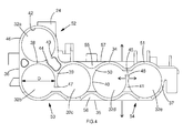
- FIGS 3 and 4 show a perspective view and a side view of the battery pack housing 24 without the battery cells 23a to 23e.
- the battery pack housing 24 is made from a thermoplastic material and is moulded as a single, unitary piece. By making the battery pack housing 24 from a single piece, assembly of the battery pack 20 is much easier and quicker.
- the battery pack housing 24 can be made from multiple pieces (not shown), for example a top piece and a bottom piece which clip together.
- the shape of the battery pack housing may be too complicated for a single moulding process and requires two moulded pieces to form the shape.
- the battery pack housing 24 comprises a top wall portion 34, a bottom wall portion 35, a first side wall portion 36 and a second side wall portion 37.
- the battery pack housing 24 as shown in reference to Figures 3 and 4 comprises a single integral element.
- the top wall portion 34, the bottom wall portion 35, the first side wall portion 36 and the second side wall portion 37 are all linked together and are part of the same integral battery pack housing 24.
- the top and bottom wall portions 34, 35 are on opposing sides of the battery pack housing 24.
- the first side wall portion 36 and the second side wall portion 37 are on opposing sides of the battery pack housing 24.
- the top, bottom and side 34, 35, 36, 37 wall portions generally define a hollow structure for receiving the battery cells 23.
- the battery pack housing 24 further comprises dividing walls 38, 39, 40 and 41.
- the dividing walls 38, 39, 40, 41 are also integral with the battery pack housing 24 and form part of the same integral element as the top, bottom and side walls 34, 35, 36, 37.
- Dividing walls 39 and 41 protrude from the top wall 34 and the bottom wall 41 respectively and dividing walls 39 and 41 respectively comprises a free end 47, 48.
- the walls of the battery pack housing 24 define a plurality of holes 32 for receiving the battery cells.
- the walls may define only one hole 32, or any number of holes.
- the holes in Figures 3 and 4 have been labelled 32a, 32b, 32c, 32d, 32e so that each hole may be distinguished from each other.
- the battery cells 23a to 23e are substantially cylindrical in shape and the holes 32a to 32e in the battery pack housing 24 define a reciprocal shape. That is the holes 32a to 32e are also substantially cylindrical in shape.
- the inside surface 42 of the battery pack housing 24 engages with the outer surface 28 (as shown in Figure 2 ) of the battery cell 23.
- the size of the holes 32a to 32e corresponds to the minimum size of the manufacturing tolerance of the battery cells 23a to 23e. This means every battery cell from a particular manufacturing process will fit snugly in the battery pack housing 24.
- the diameter D of the hole 32b is approximately equal or slightly larger than to the minimum diameter within the manufacturing tolerance of the battery 23.
- the diameter D of the hole is slightly larger than the battery such that an interference fit is provided between the inside surface 42 and the outer surface of the battery cell 23.
- each hole 32a to 32e extends along a longitudinal axis.
- the longitudinal axis of the hole 32a to 32e is aligned with the longitudinal axis of the battery cell 23 when the battery cell 23 is located in the hole 32a to 32e (as shown in Figure 2 ).
- the diameter of the battery cells 23 may vary due to manufacturing tolerances.
- the battery pack housing 24 is adapted to receive battery cells 23 which vary over a manufacturing tolerance range.
- the battery cells 23 may vary in diameter by 1.6mm over a 20mm diameter.
- the minimum diameter of the battery cell may be 18.4mm and the maximum diameter of the battery cell may be 21.6mm.
- the battery pack housing 24 comprises flexibly resilient portions which distort.
- the top wall portion 34, the bottom wall portion 35 and the diving wall 41 are all flexibly resilient parts of the wall of the battery pack housing 24.
- the flexibly resilient characteristic of the battery pack housing material means that the battery pack housing 24 will clamp the larger sized battery cell 23 as the material tries to return to its rest position.
- the rest position is the relative position of the walls of the battery pack housing 24 when no battery cells are located in the holes.
- the flexibly resilient portions mean that the battery pack housing 24 can fit all the different sized battery cells 23 over the entire manufacturing tolerance.
- the maximum distortion of the battery pack housing is such that the maximum diameter of the holes 32a to 32e will exceed the maximum diameter of the manufacturing tolerance of the battery cells 23a to 23e.
- Each hole 32a to 32e has a diameter which is slightly larger than the minimum manufacturing tolerance of the battery cell 23. In other words the smallest battery cells 23 within the manufacturing tolerance will have an interference fit in the holes 32a to 32e. If two minimum sized battery cells 23 are inserted into the holes 32b and 32c, then both the two battery cells 23 are held in place with an interference fit. In this case the battery pack housing 24 does not change shape.
- the first group 52 comprises hole 32a
- the second group 53 comprises holes 32b and 32c
- the third group 54 comprises holes 32d and 32e.
- the second and third 53, 54 groups of holes comprise a pair of holes each and each group of holes comprise a common dividing wall 39 and 42 respectively.
- the first group 54 is an arrangement for receiving a single battery cell 23.
- the single hole 32a could be used on its own.
- the single hole 32a comprises a substantially circular cross section.
- the wall 46 defining the inside surface 42 of the single hole 32a comprises an open loop and defines a "C-shaped" cross section and the inside surface 42 of the wall terminates at faces 43 and 44.
- the flexibly resilient wall 46 distorts and faces 43 and 44 move apart.
- the C-shaped cross section of wall 46 defining hole 32a clamps on the battery cell 23 as the wall 46 attempts to return to its rest position.
- the inside surface 42 of the hole 32a clamps along the entire length of the battery cell 23. This means that the inside surface 42 engages the outer surface of the battery cell and clamps along its entire length and area. This increases the frictional force between the inside surface 42 of the hole 32a and the outer surface of the battery cell 23a and provides a good fit.
- the second group 53 and third group 54 of holes are essentially the same and will be described now in reference to the third group 54 of holes only.
- the third group of holes 54 comprises a pair of adjacent holes 32d, 32e.
- Each of wall portions 50, 51 defining the holes 32d and 32e also have a C-shaped cross section similar to the first group 52.
- the holes 32d and 32e are adjacent and share a common dividing wall 41.
- the common dividing wall 41 is separated from the top wall portion 34 by longitudinal slot 45.
- Longitudinal slot 45 runs down the entire length of the hole 32d and 32e and the longitudinal slot 45 provides the C-shaped cross section.
- the longitudinal slot 45 joins the holes 32d and 32e together. This means that the common dividing wall is free to flex with respect to the battery pack housing 24(as shown in figure 4 ) leftwards, e.g. towards hole 32d or rightwards, e.g. towards hole 32e.
- the top wall portion 34 above holes 32d and 32e is not joined to the bottom wall portion 35 by the common dividing wall 41.
- top wall portion 34 is able to flex is with respect to the battery pack housing 24 upwards, e.g. away from holes 32d and 32e and bottom wall portion 35 is able to flex with respect to the battery pack housing 24 downwards e.g. away from holes 32d and 32e.
- Arrows indicate in Figure 4 how the wall portions of the batter pack housing 24 can move in the vicinity of holes 32d and 32e.
- the walls may be flexibly resilient by providing portions of the wall with a different material such as an elastomeric material.
- FIG. 5 shows a schematic side view of a portion of the battery pack housing and the third group 54.
- the battery cell 23e has a larger diameter than the hole 32e.
- the top wall portion 34 and the bottom wall portion 35 are distorted and move away from each other to accommodate the larger sized battery cell 23e.
- the top wall portion 34 and the bottom wall portion 35 then exert a clamping force on the battery cell 23e as the top and bottom wall portions 34 and 35 attempt to return to their rest positions.
- the dividing wall 41 is urged away from the larger sized battery cell 23e and towards hole 32d.
- the side walls 37 and 36 are not configured to distort substantially.
- the dividing wall 41 is more flexible because it has a free end 48 and will deflect more easily that the side walls 37, 36 or the other dividing wall 40 coupled to both the top and bottom wall portions 34, 35.
- the common dividing wall 41 flexes towards hole 32d and battery cell 23d, the dividing wall 41 will clamp against the battery cell 23d.
- the amount the dividing wall 41 flexes will depend on the size of the battery cell 23d in the hole 32d.
- the top wall portion and the bottom wall portion 34, 35 move apart around the hole 32e containing the larger sized battery cell 23e.
- the top wall portion 34 and the bottom wall portion 35 will also more albeit much less so around the adjacent hole 32d.
- the dividing wall 41 will clamp against the battery cell 23d. The clamping action of the dividing wall 41 will grip the battery cell 23d against the internal surface of the hole 32d and this will ensure a good fit even if the top wall portion 34 and the bottom wall portion 35 more away from each around hole 32d.
- the groups of holes 54, 53 are separated by a reinforced portion 55 which is thicker than the tapered portion of top wall 57 immediately above the holes 32d.
- the bottom wall 56 also comprises a similar reinforced portion 56. This means that deflection of the top wall portion 34 and the bottom wall portion 35 is localized around each group of holes. The larger battery cells located in the third group 54 of holes will not move the top wall portion 34 away from the bottom wall portion in the region of the second group 53 of holes.
- FIG. 6 shows a battery pack housing 60 which functions in the same way to the battery pack housing as discussed in respect of the previous embodiments.
- Battery pack housing 60 comprises an arcuate shape and the holes 61a to 61j receive battery cells arranged along an arcuate path.
- the battery pack housing 60 is curved so that it can fit around a curved structure in the electrical product like a motor or a cylindrical dust bowl of a vacuum cleaner.
- the battery pack housing 60 comprises pairs of holes which function in the same way to the groups of holes as mentioned in respect of Figures 3 to 5 .
- the battery pack housing 60 comprises clips 62 for clipping the battery pack housing into the electrical product (not shown).
Landscapes
- Chemical & Material Sciences (AREA)
- Chemical Kinetics & Catalysis (AREA)
- Electrochemistry (AREA)
- General Chemical & Material Sciences (AREA)
- Engineering & Computer Science (AREA)
- Mechanical Engineering (AREA)
- Battery Mounting, Suspending (AREA)
Abstract
Description
- The present invention relates to a battery pack. In particular the present invention relates to battery pack for lithium based cells.
- Battery packs for consumer electrical products often comprise battery packs for providing power to the electrical product. Typically cordless consumer electrical products will have a rechargeable battery pack. Recently much effort has been put into understanding and developing new battery technologies. Improving batteries and increasing battery capacity is desirable because this increases the run time of the cordless electrical product.
- Today most battery powered consumer electrical products will comprise a lithium ion battery pack. Lithium ion (Li-ion) based batteries packs are an improvement on other existing battery technologies such as Nickel Cadmium (NiCad) because they are lighter and have a greater energy density. However Li-ion batteries are susceptible to damage from physical shocks and require suitable protection.
- A known battery pack is shown in
US 8,343,643 which provides a support frame having a plurality of recesses for receiving a plurality of battery cells. One problem with the support frame is that unless the battery cells are manufactured to a very high tolerance, some cells will not fit the support frame properly. For example the some cells will be smaller in diameter than the recesses and the cells will be prone to rattling when located in the recesses of the support frame. -
EP 2 193 562 provides a battery pack with a housing and several battery cells. The battery cells are spaced apart from each other with a spreading element and allows battery cells with varying sizes due to manufacturing tolerances to be used in the same battery pack. A problem with this battery pack is that it the spreading elements are directional and can be inserted incorrectly. This means that the battery packs take longer and are harder to assemble. - A battery pack providing an arrangement which can withstand physical shocks and is easier to assemble is desired. Embodiments of the present invention aim to address the aforementioned problems.
- According to an aspect of the present invention there is a battery pack comprising: a first battery cell and a second battery cell, the first and second battery cells each have a size within a manufacturing tolerance; and a housing comprising at least one wall defining a first hole and a second hole each for receiving one of the first or second battery cells, each hole having a size corresponding to a minimum size within the manufacturing tolerance; and a flexibly resilient portion moveable between a rest position and a clamping position whereby the flexibly resilient portion clamps against the first and / or second battery cell when the first and / or second battery cell has a size greater than the minimum size within the manufacturing tolerance.
- Due to manufacturing processes, identical battery cells will differ slightly in size and shape. The battery cells will differ over a determined manufacturing tolerance. The housing can adapt to different sized battery cells and this means that every battery cells within the manufacturing tolerance range will fit snugly in the housing. Since the holes and the housing accommodate the size variation as soon at the battery cell is inserted into the hole, assembly is quicker because there are less parts involved.
- Preferably the flexibly resilient portion is an internal dividing wall between the first and second holes. Preferably the internal dividing wall comprises a slot connecting the first hole to the second hole. Preferably the flexibly resilient portion comprises a top wall portion of the housing and a bottom wall portion both moveable relative to each other. This means that flexibly resilient portion of the housing can be integral with the housing.
- Preferably the cross section shape of the first and second holes and the first and second battery cells is circular. Preferably an inside surface of the first and / or second hole is engageable with the outer surface of the first and / or second battery cell along substantially the entire longitudinal axis of the first and / or second battery cell. This means that the entire surface can be used for the interference fit and can provide the best possible fit.
- Preferably the first and second battery cells are lithium based battery cells.
- Preferably the housing is mounted within a protective outer shell.
- Preferably each hole has a size corresponding to a minimum size within the manufacturing tolerance such that the first and second battery cells are held in the first and second holes with an interference fit.
- Preferably housing further comprises a plurality of groups of first and second holes and first and second battery cells, each group comprising a separate flexible resilient portion. The structure as recited in the first aspect can be repeated any number of times to provide battery packs with any number of batteries.
- Preferably the housing is a unitary moulded element. This means that there are less parts during manufacture and assembly of the battery packs is quicker.
- According to another aspect of the present invention there is provided a method of manufacturing a battery pack comprising:
- moulding a housing comprising at least one wall defining a first hole and a second hole each for receiving one of a first or a second battery cell, each hole having a size corresponding to a minimum size within a manufacturing tolerance of the size of the first and second batteries; and a flexibly resilient portion moveable between a rest position and a clamping position whereby the flexibly resilient portion clamps against the first and / or second battery cell when the first and / or second battery cell has a size greater than the minimum size within the manufacturing tolerance; and
- inserting the first and second battery cells into the first and second holes respectively.
- Various other aspects and further embodiments are also described in the following detailed description and in the attached claims with reference to the accompanying drawings, in which:
-
Figure 1 shows a perspective view of an electrical consumer product comprising a battery pack according to one embodiment; -
Figure 2 shows a perspective view of the battery pack according to one embodiment; -
Figure 3 shows a perspective view of the battery pack housing according to one embodiment; -
Figure 4 shows a side view of the battery pack housing according to one embodiment; -
Figure 5 shows a partial schematic side view of the battery pack housing according to one embodiment; and -
Figure 6 shows a side view of the battery pack housing according to another embodiment. -
Figure 1 shows a perspective view of anelectrical consumer product 10. In this particular example the electrical consumer product is a vacuum cleaner but the battery pack described herein could be used for any electrical product.Figure 1 shows thevacuum cleaner 10 without a side panel and exposes thebattery pack 20 mounted within thehousing 30 of thevacuum cleaner 10. Thebattery pack 20 may be clipped to thehousing 30 or fixed in place with any other suitable means such as screws or glue. Thevacuum cleaner 10 comprises a motor coupled to a fan (both not shown) and the motor is electrically coupled to thebattery pack 20. - The
battery pack 20 comprises an optional outer shell having afirst part 21 and asecond part 22. The optional outer shell provides additional physical protection to the battery cells mounted therein. The first part and thesecond part -
Figure 2 shows a perspective view of abattery pack 20 without the optional outer shell.Figure 2 shows fivebattery cells battery pack housing 24, but in other embodiments there may a different number of battery cells. In some embodiments there may be a single pair of battery cells housed in thebattery pack housing 24. Alternatively there may be any number of battery cells. A printed circuit board (PCB) 25 for controlling the charging and discharging of the battery cells 23 is mounted on thebattery housing 24. ThePCB 25 and its controlling functions are known and are not described in any further detail. The PCB 25 is mounted to thehousing 24 with ascrew 26. - Each of the
battery cells 23a to 23e are connected to thePCB 25 by anelectrical connecting plate 27. Typically thebattery cells 23a to 23e are electrically connected together in series, but thebattery cells 23a to 23e may be electrically connected together in alternative ways. - In some embodiments the
battery cells 23a to 23e are lithium based cells. Thebattery cells 23a to 23e can be Li-ion cells, lithium polymer cells, lithium metal cells or any other lithium based cell. Li-ion cells are vulnerable to physical shock and thehousing 24 provides protection to the Li-ion cells. In other embodiments thebattery cells 23a to 23e can be any other type of battery cell. - Turning to
Figures 3 and4 , the structure ofbattery pack housing 24 will now be discussed in further detail.Figures 3 and4 show a perspective view and a side view of thebattery pack housing 24 without thebattery cells 23a to 23e. Thebattery pack housing 24 is made from a thermoplastic material and is moulded as a single, unitary piece. By making thebattery pack housing 24 from a single piece, assembly of thebattery pack 20 is much easier and quicker. - However in other embodiments the
battery pack housing 24 can be made from multiple pieces (not shown), for example a top piece and a bottom piece which clip together. For example, in some circumstances the shape of the battery pack housing may be too complicated for a single moulding process and requires two moulded pieces to form the shape. - Referring to
Figure 4 , thebattery pack housing 24 comprises atop wall portion 34, abottom wall portion 35, a firstside wall portion 36 and a secondside wall portion 37. Thebattery pack housing 24 as shown in reference toFigures 3 and4 comprises a single integral element. Thetop wall portion 34, thebottom wall portion 35, the firstside wall portion 36 and the secondside wall portion 37 are all linked together and are part of the same integralbattery pack housing 24. The top andbottom wall portions battery pack housing 24. Similarly the firstside wall portion 36 and the secondside wall portion 37 are on opposing sides of thebattery pack housing 24. - The top, bottom and
side battery pack housing 24 further comprises dividingwalls walls battery pack housing 24 and form part of the same integral element as the top, bottom andside walls walls top wall 34 and thebottom wall 41 respectively and dividingwalls free end - The walls of the
battery pack housing 24 define a plurality of holes 32 for receiving the battery cells. Of course the walls may define only one hole 32, or any number of holes. The holes inFigures 3 and4 have been labelled 32a, 32b, 32c, 32d, 32e so that each hole may be distinguished from each other. - The
battery cells 23a to 23e are substantially cylindrical in shape and theholes 32a to 32e in thebattery pack housing 24 define a reciprocal shape. That is theholes 32a to 32e are also substantially cylindrical in shape. When the battery cells 23 are inserted into one of theholes 32a to 32e theinside surface 42 of thebattery pack housing 24 engages with the outer surface 28 (as shown inFigure 2 ) of the battery cell 23. - The size of the
holes 32a to 32e corresponds to the minimum size of the manufacturing tolerance of thebattery cells 23a to 23e. This means every battery cell from a particular manufacturing process will fit snugly in thebattery pack housing 24. In reference toFigure 4 , the diameter D of thehole 32b is approximately equal or slightly larger than to the minimum diameter within the manufacturing tolerance of the battery 23. The diameter D of the hole is slightly larger than the battery such that an interference fit is provided between theinside surface 42 and the outer surface of the battery cell 23. - Each
hole 32a to 32e has the same diameter D for receiving the battery cells of the same size and shape. This means a frictional force between thebattery pack housing 24 and each battery cell 23 holds the battery cells 23 in place. In other embodiments the battery cells are not cylindrical and may have another cross sectional shape for example, triangular, rectangular or square and theholes 32a to 32e will be reciprocally shaped. - As can be seen from
Figure 3 , eachhole 32a to 32e extends along a longitudinal axis. The longitudinal axis of thehole 32a to 32e is aligned with the longitudinal axis of the battery cell 23 when the battery cell 23 is located in thehole 32a to 32e (as shown inFigure 2 ). - Use and assembly of the
battery pack housing 24 will now be discussed. - The diameter of the battery cells 23 may vary due to manufacturing tolerances. The
battery pack housing 24 is adapted to receive battery cells 23 which vary over a manufacturing tolerance range. For example, the battery cells 23 may vary in diameter by 1.6mm over a 20mm diameter. The minimum diameter of the battery cell may be 18.4mm and the maximum diameter of the battery cell may be 21.6mm. Thebattery pack housing 24 comprises flexibly resilient portions which distort. For example thetop wall portion 34, thebottom wall portion 35 and thediving wall 41 are all flexibly resilient parts of the wall of thebattery pack housing 24. When a larger sized battery (with a diameter larger than the minimum diameter of the manufacturing tolerance and diameter D of theholes 32a to 32e) is put in a hole, a portion of thebattery pack 24 will flex to accommodate variation in the sizes of the battery cells. - The flexibly resilient characteristic of the battery pack housing material means that the
battery pack housing 24 will clamp the larger sized battery cell 23 as the material tries to return to its rest position. The rest position is the relative position of the walls of thebattery pack housing 24 when no battery cells are located in the holes. The flexibly resilient portions mean that thebattery pack housing 24 can fit all the different sized battery cells 23 over the entire manufacturing tolerance. - The maximum distortion of the battery pack housing is such that the maximum diameter of the
holes 32a to 32e will exceed the maximum diameter of the manufacturing tolerance of thebattery cells 23a to 23e. - Each
hole 32a to 32e has a diameter which is slightly larger than the minimum manufacturing tolerance of the battery cell 23. In other words the smallest battery cells 23 within the manufacturing tolerance will have an interference fit in theholes 32a to 32e. If two minimum sized battery cells 23 are inserted into theholes battery pack housing 24 does not change shape. - The
battery pack housing 24 is arranged to flex along different directions depending on the size of the battery cell being inserted into theholes 32a to 32e. -
Battery pack housing 24 comprises three groups ofholes batter pack housing 24 and movement of the shared flexible portions of wall affect the fit of the battery cells in the holes of the group. There may be any number of groups of holes in thebattery pack housing 24. - The
first group 52 compriseshole 32a, thesecond group 53 comprisesholes third group 54 comprisesholes common dividing wall - The
first group 54 is an arrangement for receiving a single battery cell 23. Thesingle hole 32a could be used on its own. Thesingle hole 32a comprises a substantially circular cross section. Thewall 46 defining theinside surface 42 of thesingle hole 32a comprises an open loop and defines a "C-shaped" cross section and theinside surface 42 of the wall terminates at faces 43 and 44. When battery cell 23 is inserted intohole 32a which has a larger diameter than thehole 32a, the flexiblyresilient wall 46 distorts and faces 43 and 44 move apart. The C-shaped cross section ofwall 46 defininghole 32a clamps on the battery cell 23 as thewall 46 attempts to return to its rest position. Theinside surface 42 of thehole 32a clamps along the entire length of the battery cell 23. This means that theinside surface 42 engages the outer surface of the battery cell and clamps along its entire length and area. This increases the frictional force between theinside surface 42 of thehole 32a and the outer surface of thebattery cell 23a and provides a good fit. - The
second group 53 andthird group 54 of holes are essentially the same and will be described now in reference to thethird group 54 of holes only. The third group ofholes 54 comprises a pair ofadjacent holes wall portions holes first group 52. - The
holes common dividing wall 41. Thecommon dividing wall 41 is separated from thetop wall portion 34 bylongitudinal slot 45.Longitudinal slot 45 runs down the entire length of thehole longitudinal slot 45 provides the C-shaped cross section. Thelongitudinal slot 45 joins theholes figure 4 ) leftwards, e.g. towardshole 32d or rightwards, e.g. towardshole 32e. Furthermore thetop wall portion 34 aboveholes bottom wall portion 35 by thecommon dividing wall 41. This means that thetop wall portion 34 is able to flex is with respect to thebattery pack housing 24 upwards, e.g. away fromholes bottom wall portion 35 is able to flex with respect to thebattery pack housing 24 downwards e.g. away fromholes Figure 4 how the wall portions of thebatter pack housing 24 can move in the vicinity ofholes - Instead of providing a slot and separating the walls from each other, in alternative embodiments the walls may be flexibly resilient by providing portions of the wall with a different material such as an elastomeric material.
- A larger
diameter battery cell 23e is placed intohole 32e as shown inFigure 5. Figure 5 shows a schematic side view of a portion of the battery pack housing and thethird group 54. Thebattery cell 23e has a larger diameter than thehole 32e. Thetop wall portion 34 and thebottom wall portion 35 are distorted and move away from each other to accommodate the largersized battery cell 23e. Thetop wall portion 34 and thebottom wall portion 35 then exert a clamping force on thebattery cell 23e as the top andbottom wall portions - At the same time the dividing
wall 41 is urged away from the largersized battery cell 23e and towardshole 32d. Theside walls wall 41 is more flexible because it has afree end 48 and will deflect more easily that theside walls wall 40 coupled to both the top andbottom wall portions common dividing wall 41 flexes towardshole 32d andbattery cell 23d, the dividingwall 41 will clamp against thebattery cell 23d. The amount the dividingwall 41 flexes will depend on the size of thebattery cell 23d in thehole 32d. - The greatest amount of deflection of the dividing
wall 41 will occur when a maximum sized (within the manufacturing tolerance)battery cell 23e is located adjacent to a minimumsized battery cell 23d. The minimumsized battery 23d would normally be held in place with an interference fit inhole 32d. However the largersized battery cell 23e located in theadjacent hole 32e will affect the normal interference fit in theadjacent hole 32d. - As mentioned, the top wall portion and the
bottom wall portion hole 32e containing the largersized battery cell 23e. Thetop wall portion 34 and thebottom wall portion 35 will also more albeit much less so around theadjacent hole 32d. When thebattery cell 23d is the minimum size, the dividingwall 41 will clamp against thebattery cell 23d. The clamping action of the dividingwall 41 will grip thebattery cell 23d against the internal surface of thehole 32d and this will ensure a good fit even if thetop wall portion 34 and thebottom wall portion 35 more away from each aroundhole 32d. - If two equal larger sized battery cells are located adjacent to each other then only the top wall portion and the bottom wall portion will move apart. The dividing wall portion will remain centrally between the two
holes - The groups of
holes portion 55 which is thicker than the tapered portion oftop wall 57 immediately above theholes 32d. Thebottom wall 56 also comprises a similar reinforcedportion 56. This means that deflection of thetop wall portion 34 and thebottom wall portion 35 is localized around each group of holes. The larger battery cells located in thethird group 54 of holes will not move thetop wall portion 34 away from the bottom wall portion in the region of thesecond group 53 of holes. - Another embodiment will now be discussed in reference to
Figure 6. Figure 6 shows abattery pack housing 60 which functions in the same way to the battery pack housing as discussed in respect of the previous embodiments.Battery pack housing 60 comprises an arcuate shape and theholes 61a to 61j receive battery cells arranged along an arcuate path. Thebattery pack housing 60 is curved so that it can fit around a curved structure in the electrical product like a motor or a cylindrical dust bowl of a vacuum cleaner. Thebattery pack housing 60 comprises pairs of holes which function in the same way to the groups of holes as mentioned in respect ofFigures 3 to 5 . Thebattery pack housing 60 comprisesclips 62 for clipping the battery pack housing into the electrical product (not shown). - In another embodiment two or more embodiments are combined. Features of one embodiment can be combined with features of other embodiments.
- Embodiments of the present invention have been discussed with particular reference to the examples illustrated. However it will be appreciated that variations and modifications may be made to the examples described within the scope of the invention.
Claims (12)
- A battery pack comprising:a first battery cell and a second battery cell, the first and second battery cells each have a size within a manufacturing tolerance; anda housing comprising at least one wall defining a first hole and a second hole each for receiving one of the first or second battery cells, each hole having a size corresponding to a minimum size within the manufacturing tolerance; anda flexibly resilient portion moveable between a rest position and a clamping position whereby the flexibly resilient portion clamps against the first and / or second battery cell when the first and / or second battery cell has a size greater than the minimum size within the manufacturing tolerance.
- A battery pack according to claim 1 wherein the flexibly resilient portion is an internal dividing wall between the first and second holes.
- A battery pack according to claim 2 wherein the internal dividing wall comprises a slot connecting the first hole to the second hole.
- A battery pack according any of claims 1 to 3 wherein the flexibly resilient portion comprises a top wall portion of the housing and a bottom wall portion both moveable relative to each other.
- A battery pack according to any of the preceding claims wherein the housing is a unitary moulded element.
- A battery pack according to any of the preceding claims wherein the cross section shape of the first and second holes and the first and second battery cells is circular.
- A battery pack according to any of preceding claims wherein an inside surface of the first and / or second hole is engageable with the outer surface of the first and / or second battery cell along substantially the entire longitudinal axis of the first and / or second battery cell.
- A battery pack according to any of the preceding claims wherein the first and second battery cells are lithium based battery cells.
- A battery pack according to any of the preceding claims wherein the housing is mounted within a protective outer shell.
- A battery pack according to any of the preceding claims wherein each hole has a size corresponding to a minimum size within the manufacturing tolerance such that the first and second battery cells are held in the first and second holes with an interference fit.
- A battery pack according to any of the preceding claims wherein housing further comprises a plurality of groups of first and second holes and first and second battery cells, each group comprising a separate flexible resilient portion.
- A method of manufacturing a battery pack comprising:moulding a housing comprising at least one wall defining a first hole and a second hole each for receiving one of a first or a second battery cell, each hole having a size corresponding to a minimum size within a manufacturing tolerance of the size of the first and second batteries; and a flexibly resilient portion moveable between a rest position and a clamping position whereby the flexibly resilient portion clamps against the first and / or second battery cell when the first and / or second battery cell has a size greater than the minimum size within the manufacturing tolerance; andinserting the first and second battery cells into the first and second holes respectively.
Applications Claiming Priority (1)
| Application Number | Priority Date | Filing Date | Title |
|---|---|---|---|
| GB1401197.7A GB2522447A (en) | 2014-01-24 | 2014-01-24 | Battery pack |
Publications (2)
| Publication Number | Publication Date |
|---|---|
| EP2899774A1 true EP2899774A1 (en) | 2015-07-29 |
| EP2899774B1 EP2899774B1 (en) | 2018-09-19 |
Family
ID=50287495
Family Applications (1)
| Application Number | Title | Priority Date | Filing Date |
|---|---|---|---|
| EP14191793.0A Active EP2899774B1 (en) | 2014-01-24 | 2014-11-05 | Battery pack |
Country Status (4)
| Country | Link |
|---|---|
| US (1) | US9806301B2 (en) |
| EP (1) | EP2899774B1 (en) |
| CN (1) | CN104810487B (en) |
| GB (1) | GB2522447A (en) |
Cited By (1)
| Publication number | Priority date | Publication date | Assignee | Title |
|---|---|---|---|---|
| GB2540437A (en) * | 2015-07-17 | 2017-01-18 | Johnson Matthey Plc | Cell tray |
Families Citing this family (10)
| Publication number | Priority date | Publication date | Assignee | Title |
|---|---|---|---|---|
| US9843078B2 (en) * | 2014-02-18 | 2017-12-12 | DG Systems, LLC | Unitized energy storage system enclosure |
| FR3042657B1 (en) | 2015-10-16 | 2018-07-27 | Bubendorff | DEVICE FOR SUPPLYING OR CONTROLLING AN ELECTRIC MOTOR |
| US10376766B2 (en) | 2016-07-29 | 2019-08-13 | Black & Decker Inc. | Scoreboard and system |
| CN107785600A (en) * | 2016-08-31 | 2018-03-09 | 惠州市金能源科技有限公司 | A kind of large size battery assembling jig |
| US11811259B2 (en) | 2017-03-17 | 2023-11-07 | Renew Health Ltd | Power pack |
| CN106992274A (en) * | 2017-05-08 | 2017-07-28 | 江苏铁锚工具有限公司 | A kind of battery compartment and its level for level |
| CN107910469B (en) * | 2017-12-01 | 2023-07-25 | 上海捷科工具有限公司 | Double-row battery pack |
| JP7063385B2 (en) * | 2018-08-06 | 2022-05-09 | 株式会社村田製作所 | Battery holders, battery packs, electronic devices and electric vehicles |
| DE102019213965A1 (en) * | 2019-09-04 | 2021-03-04 | Robert Bosch Gmbh | Cell holder for a plurality of cylindrical Li-ion cells, handheld power tool battery pack with such a cell holder, as well as a system with a handheld power tool and such a handheld power tool battery pack |
| EP4109648B1 (en) * | 2021-06-23 | 2025-05-21 | Orbea, S. Coop. | Compact battery for electric bicycles |
Citations (6)
| Publication number | Priority date | Publication date | Assignee | Title |
|---|---|---|---|---|
| US4593461A (en) * | 1983-08-12 | 1986-06-10 | Enetronics, Inc. | Power cell assembly |
| WO2001028008A1 (en) * | 1999-10-13 | 2001-04-19 | Johnson Controls Technology Company | Composite battery container with integral flexible ribs |
| US6458481B1 (en) * | 2000-05-13 | 2002-10-01 | Motorola Inc. | Tolerance and size adaptive spacer for spacing a battery cell |
| EP2495786A1 (en) * | 2011-03-03 | 2012-09-05 | Brusa Elektronik AG | Stackable holder for a rechargeable battery cell, modular system and rechargeable battery |
| US20120225340A1 (en) * | 2011-03-01 | 2012-09-06 | Willis Jay Mullet | Battery holder apparatus and method |
| EP2600439A2 (en) * | 2011-11-29 | 2013-06-05 | Yokogawa Electric Corporation | Battery storage device |
Family Cites Families (13)
| Publication number | Priority date | Publication date | Assignee | Title |
|---|---|---|---|---|
| JPS60124352A (en) * | 1983-12-08 | 1985-07-03 | Canon Inc | Battery holding device |
| JPH03190052A (en) * | 1989-12-18 | 1991-08-20 | Sanyo Electric Co Ltd | Battery pack |
| US5589288A (en) * | 1995-07-31 | 1996-12-31 | Black & Decker, Inc. | Cordless power tool having a push button battery release arrangement |
| JP3662485B2 (en) * | 2000-08-31 | 2005-06-22 | 松下電器産業株式会社 | Battery pack |
| US6824917B2 (en) * | 2001-12-11 | 2004-11-30 | Nokia Corporation | Battery system for a portable electronic device |
| DE102004043822A1 (en) * | 2004-09-10 | 2006-03-16 | Robert Bosch Gmbh | battery Pack |
| JP5370709B2 (en) * | 2007-10-29 | 2013-12-18 | 日立工機株式会社 | Battery pack and electric tool equipped with the same |
| DE102007021309A1 (en) * | 2007-05-07 | 2008-11-13 | Valeo Klimasysteme Gmbh | Drive battery assembly of an electric, fuel cell or hybrid vehicle |
| WO2009040200A1 (en) | 2007-09-21 | 2009-04-02 | Robert Bosch Gmbh | Battery pack |
| KR101270593B1 (en) * | 2010-07-16 | 2013-06-03 | 주식회사 엘지화학 | Pack Case of Novel Structure |
| US8343643B2 (en) | 2010-08-20 | 2013-01-01 | Techtronic Power Tools Technology Limited | Battery pack including a support frame |
| EP2500961B1 (en) * | 2011-03-15 | 2017-07-26 | Johnson Controls Automotive Electronics GmbH | Housing arrangement for an electrical energy storage |
| DE102011114526A1 (en) * | 2011-09-29 | 2013-04-04 | Bmz Batterien-Montage-Zentrum Gmbh | Holding device for holding rechargeable battery cell, has resilient clamping units which are arranged transversely in interior of recesses, to prevent movement of electrical energy accumulators about longitudinal axis of recesses |
-
2014
- 2014-01-24 GB GB1401197.7A patent/GB2522447A/en not_active Withdrawn
- 2014-11-05 EP EP14191793.0A patent/EP2899774B1/en active Active
-
2015
- 2015-01-22 US US14/602,751 patent/US9806301B2/en active Active
- 2015-01-23 CN CN201510037283.1A patent/CN104810487B/en not_active Expired - Fee Related
Patent Citations (6)
| Publication number | Priority date | Publication date | Assignee | Title |
|---|---|---|---|---|
| US4593461A (en) * | 1983-08-12 | 1986-06-10 | Enetronics, Inc. | Power cell assembly |
| WO2001028008A1 (en) * | 1999-10-13 | 2001-04-19 | Johnson Controls Technology Company | Composite battery container with integral flexible ribs |
| US6458481B1 (en) * | 2000-05-13 | 2002-10-01 | Motorola Inc. | Tolerance and size adaptive spacer for spacing a battery cell |
| US20120225340A1 (en) * | 2011-03-01 | 2012-09-06 | Willis Jay Mullet | Battery holder apparatus and method |
| EP2495786A1 (en) * | 2011-03-03 | 2012-09-05 | Brusa Elektronik AG | Stackable holder for a rechargeable battery cell, modular system and rechargeable battery |
| EP2600439A2 (en) * | 2011-11-29 | 2013-06-05 | Yokogawa Electric Corporation | Battery storage device |
Cited By (1)
| Publication number | Priority date | Publication date | Assignee | Title |
|---|---|---|---|---|
| GB2540437A (en) * | 2015-07-17 | 2017-01-18 | Johnson Matthey Plc | Cell tray |
Also Published As
| Publication number | Publication date |
|---|---|
| GB201401197D0 (en) | 2014-03-12 |
| CN104810487A (en) | 2015-07-29 |
| EP2899774B1 (en) | 2018-09-19 |
| US9806301B2 (en) | 2017-10-31 |
| US20150214519A1 (en) | 2015-07-30 |
| GB2522447A (en) | 2015-07-29 |
| CN104810487B (en) | 2018-03-13 |
Similar Documents
| Publication | Publication Date | Title |
|---|---|---|
| EP2899774B1 (en) | Battery pack | |
| CN106340607B (en) | Battery pack | |
| US20230327256A1 (en) | Support member for battery pack top housing | |
| US7118827B2 (en) | Battery assembly and method of making same | |
| US11088388B2 (en) | Clamping member and battery module using the same | |
| JP7276491B2 (en) | Battery packs and electrical equipment | |
| EP2787559B1 (en) | Battery pack for electric power tool | |
| EP2355209B1 (en) | Battery system with service plug connection | |
| US7806374B1 (en) | Cable grommet | |
| EP2062310B1 (en) | Battery pack and motor-driven tool using the same | |
| EP2390941B1 (en) | Battery pack | |
| JP5452252B2 (en) | Battery system | |
| EP2533350A1 (en) | Battery module with improved heat exchange efficiency | |
| KR102317503B1 (en) | Battery Pack | |
| EP3166160B1 (en) | Compact secondary battery module and secondary battery pack using same | |
| EP4060801A1 (en) | Battery pack including handle-locking mechanism | |
| KR20170074543A (en) | Secondary battery module improved in preventing structure of battery overcharge | |
| EP2365560A1 (en) | Battery pack with lead-plates | |
| CN107039611B (en) | Battery pack | |
| KR20160039417A (en) | Battery Pack Having Heat Radiation Structure | |
| CN106467050B (en) | Dual-forming handle spacer for motor vehicle | |
| WO2024002621A1 (en) | A holder member and a battery pack with the same | |
| CN213546516U (en) | Parallel battery with reliable connection | |
| CN214948677U (en) | Gun lamp structure convenient for replacing battery pack | |
| CN115566336B (en) | A solid-state battery |
Legal Events
| Date | Code | Title | Description |
|---|---|---|---|
| PUAI | Public reference made under article 153(3) epc to a published international application that has entered the european phase |
Free format text: ORIGINAL CODE: 0009012 |
|
| 17P | Request for examination filed |
Effective date: 20141105 |
|
| AK | Designated contracting states |
Kind code of ref document: A1 Designated state(s): AL AT BE BG CH CY CZ DE DK EE ES FI FR GB GR HR HU IE IS IT LI LT LU LV MC MK MT NL NO PL PT RO RS SE SI SK SM TR |
|
| AX | Request for extension of the european patent |
Extension state: BA ME |
|
| 17P | Request for examination filed |
Effective date: 20160125 |
|
| RBV | Designated contracting states (corrected) |
Designated state(s): AL AT BE BG CH CY CZ DE DK EE ES FI FR GB GR HR HU IE IS IT LI LT LU LV MC MK MT NL NO PL PT RO RS SE SI SK SM TR |
|
| STAA | Information on the status of an ep patent application or granted ep patent |
Free format text: STATUS: EXAMINATION IS IN PROGRESS |
|
| 17Q | First examination report despatched |
Effective date: 20161222 |
|
| GRAP | Despatch of communication of intention to grant a patent |
Free format text: ORIGINAL CODE: EPIDOSNIGR1 |
|
| STAA | Information on the status of an ep patent application or granted ep patent |
Free format text: STATUS: GRANT OF PATENT IS INTENDED |
|
| INTG | Intention to grant announced |
Effective date: 20180420 |
|
| GRAS | Grant fee paid |
Free format text: ORIGINAL CODE: EPIDOSNIGR3 |
|
| GRAA | (expected) grant |
Free format text: ORIGINAL CODE: 0009210 |
|
| STAA | Information on the status of an ep patent application or granted ep patent |
Free format text: STATUS: THE PATENT HAS BEEN GRANTED |
|
| AK | Designated contracting states |
Kind code of ref document: B1 Designated state(s): AL AT BE BG CH CY CZ DE DK EE ES FI FR GB GR HR HU IE IS IT LI LT LU LV MC MK MT NL NO PL PT RO RS SE SI SK SM TR |
|
| REG | Reference to a national code |
Ref country code: GB Ref legal event code: FG4D |
|
| REG | Reference to a national code |
Ref country code: CH Ref legal event code: EP |
|
| REG | Reference to a national code |
Ref country code: FR Ref legal event code: PLFP Year of fee payment: 5 |
|
| REG | Reference to a national code |
Ref country code: AT Ref legal event code: REF Ref document number: 1044276 Country of ref document: AT Kind code of ref document: T Effective date: 20181015 |
|
| REG | Reference to a national code |
Ref country code: IE Ref legal event code: FG4D |
|
| REG | Reference to a national code |
Ref country code: DE Ref legal event code: R096 Ref document number: 602014032453 Country of ref document: DE |
|
| REG | Reference to a national code |
Ref country code: NL Ref legal event code: MP Effective date: 20180919 |
|
| PG25 | Lapsed in a contracting state [announced via postgrant information from national office to epo] |
Ref country code: BG Free format text: LAPSE BECAUSE OF FAILURE TO SUBMIT A TRANSLATION OF THE DESCRIPTION OR TO PAY THE FEE WITHIN THE PRESCRIBED TIME-LIMIT Effective date: 20181219 Ref country code: GR Free format text: LAPSE BECAUSE OF FAILURE TO SUBMIT A TRANSLATION OF THE DESCRIPTION OR TO PAY THE FEE WITHIN THE PRESCRIBED TIME-LIMIT Effective date: 20181220 Ref country code: LT Free format text: LAPSE BECAUSE OF FAILURE TO SUBMIT A TRANSLATION OF THE DESCRIPTION OR TO PAY THE FEE WITHIN THE PRESCRIBED TIME-LIMIT Effective date: 20180919 Ref country code: SE Free format text: LAPSE BECAUSE OF FAILURE TO SUBMIT A TRANSLATION OF THE DESCRIPTION OR TO PAY THE FEE WITHIN THE PRESCRIBED TIME-LIMIT Effective date: 20180919 Ref country code: NO Free format text: LAPSE BECAUSE OF FAILURE TO SUBMIT A TRANSLATION OF THE DESCRIPTION OR TO PAY THE FEE WITHIN THE PRESCRIBED TIME-LIMIT Effective date: 20181219 Ref country code: FI Free format text: LAPSE BECAUSE OF FAILURE TO SUBMIT A TRANSLATION OF THE DESCRIPTION OR TO PAY THE FEE WITHIN THE PRESCRIBED TIME-LIMIT Effective date: 20180919 Ref country code: RS Free format text: LAPSE BECAUSE OF FAILURE TO SUBMIT A TRANSLATION OF THE DESCRIPTION OR TO PAY THE FEE WITHIN THE PRESCRIBED TIME-LIMIT Effective date: 20180919 |
|
| REG | Reference to a national code |
Ref country code: LT Ref legal event code: MG4D |
|
| PG25 | Lapsed in a contracting state [announced via postgrant information from national office to epo] |
Ref country code: HR Free format text: LAPSE BECAUSE OF FAILURE TO SUBMIT A TRANSLATION OF THE DESCRIPTION OR TO PAY THE FEE WITHIN THE PRESCRIBED TIME-LIMIT Effective date: 20180919 Ref country code: AL Free format text: LAPSE BECAUSE OF FAILURE TO SUBMIT A TRANSLATION OF THE DESCRIPTION OR TO PAY THE FEE WITHIN THE PRESCRIBED TIME-LIMIT Effective date: 20180919 Ref country code: LV Free format text: LAPSE BECAUSE OF FAILURE TO SUBMIT A TRANSLATION OF THE DESCRIPTION OR TO PAY THE FEE WITHIN THE PRESCRIBED TIME-LIMIT Effective date: 20180919 |
|
| PGFP | Annual fee paid to national office [announced via postgrant information from national office to epo] |
Ref country code: CH Payment date: 20181129 Year of fee payment: 13 |
|
| REG | Reference to a national code |
Ref country code: AT Ref legal event code: MK05 Ref document number: 1044276 Country of ref document: AT Kind code of ref document: T Effective date: 20180919 |
|
| PG25 | Lapsed in a contracting state [announced via postgrant information from national office to epo] |
Ref country code: CZ Free format text: LAPSE BECAUSE OF FAILURE TO SUBMIT A TRANSLATION OF THE DESCRIPTION OR TO PAY THE FEE WITHIN THE PRESCRIBED TIME-LIMIT Effective date: 20180919 Ref country code: RO Free format text: LAPSE BECAUSE OF FAILURE TO SUBMIT A TRANSLATION OF THE DESCRIPTION OR TO PAY THE FEE WITHIN THE PRESCRIBED TIME-LIMIT Effective date: 20180919 Ref country code: EE Free format text: LAPSE BECAUSE OF FAILURE TO SUBMIT A TRANSLATION OF THE DESCRIPTION OR TO PAY THE FEE WITHIN THE PRESCRIBED TIME-LIMIT Effective date: 20180919 Ref country code: IT Free format text: LAPSE BECAUSE OF FAILURE TO SUBMIT A TRANSLATION OF THE DESCRIPTION OR TO PAY THE FEE WITHIN THE PRESCRIBED TIME-LIMIT Effective date: 20180919 Ref country code: NL Free format text: LAPSE BECAUSE OF FAILURE TO SUBMIT A TRANSLATION OF THE DESCRIPTION OR TO PAY THE FEE WITHIN THE PRESCRIBED TIME-LIMIT Effective date: 20180919 Ref country code: AT Free format text: LAPSE BECAUSE OF FAILURE TO SUBMIT A TRANSLATION OF THE DESCRIPTION OR TO PAY THE FEE WITHIN THE PRESCRIBED TIME-LIMIT Effective date: 20180919 Ref country code: ES Free format text: LAPSE BECAUSE OF FAILURE TO SUBMIT A TRANSLATION OF THE DESCRIPTION OR TO PAY THE FEE WITHIN THE PRESCRIBED TIME-LIMIT Effective date: 20180919 Ref country code: IS Free format text: LAPSE BECAUSE OF FAILURE TO SUBMIT A TRANSLATION OF THE DESCRIPTION OR TO PAY THE FEE WITHIN THE PRESCRIBED TIME-LIMIT Effective date: 20190119 Ref country code: PL Free format text: LAPSE BECAUSE OF FAILURE TO SUBMIT A TRANSLATION OF THE DESCRIPTION OR TO PAY THE FEE WITHIN THE PRESCRIBED TIME-LIMIT Effective date: 20180919 |
|
| PG25 | Lapsed in a contracting state [announced via postgrant information from national office to epo] |
Ref country code: SM Free format text: LAPSE BECAUSE OF FAILURE TO SUBMIT A TRANSLATION OF THE DESCRIPTION OR TO PAY THE FEE WITHIN THE PRESCRIBED TIME-LIMIT Effective date: 20180919 Ref country code: PT Free format text: LAPSE BECAUSE OF FAILURE TO SUBMIT A TRANSLATION OF THE DESCRIPTION OR TO PAY THE FEE WITHIN THE PRESCRIBED TIME-LIMIT Effective date: 20190119 Ref country code: SK Free format text: LAPSE BECAUSE OF FAILURE TO SUBMIT A TRANSLATION OF THE DESCRIPTION OR TO PAY THE FEE WITHIN THE PRESCRIBED TIME-LIMIT Effective date: 20180919 |
|
| REG | Reference to a national code |
Ref country code: DE Ref legal event code: R097 Ref document number: 602014032453 Country of ref document: DE |
|
| REG | Reference to a national code |
Ref country code: CH Ref legal event code: PL |
|
| PLBE | No opposition filed within time limit |
Free format text: ORIGINAL CODE: 0009261 |
|
| STAA | Information on the status of an ep patent application or granted ep patent |
Free format text: STATUS: NO OPPOSITION FILED WITHIN TIME LIMIT |
|
| PG25 | Lapsed in a contracting state [announced via postgrant information from national office to epo] |
Ref country code: MC Free format text: LAPSE BECAUSE OF FAILURE TO SUBMIT A TRANSLATION OF THE DESCRIPTION OR TO PAY THE FEE WITHIN THE PRESCRIBED TIME-LIMIT Effective date: 20180919 Ref country code: LU Free format text: LAPSE BECAUSE OF NON-PAYMENT OF DUE FEES Effective date: 20181105 Ref country code: DK Free format text: LAPSE BECAUSE OF FAILURE TO SUBMIT A TRANSLATION OF THE DESCRIPTION OR TO PAY THE FEE WITHIN THE PRESCRIBED TIME-LIMIT Effective date: 20180919 |
|
| REG | Reference to a national code |
Ref country code: BE Ref legal event code: MM Effective date: 20181130 |
|
| REG | Reference to a national code |
Ref country code: IE Ref legal event code: MM4A |
|
| 26N | No opposition filed |
Effective date: 20190620 |
|
| PG25 | Lapsed in a contracting state [announced via postgrant information from national office to epo] |
Ref country code: LI Free format text: LAPSE BECAUSE OF NON-PAYMENT OF DUE FEES Effective date: 20181130 Ref country code: CH Free format text: LAPSE BECAUSE OF NON-PAYMENT OF DUE FEES Effective date: 20181130 |
|
| PG25 | Lapsed in a contracting state [announced via postgrant information from national office to epo] |
Ref country code: IE Free format text: LAPSE BECAUSE OF NON-PAYMENT OF DUE FEES Effective date: 20181105 Ref country code: SI Free format text: LAPSE BECAUSE OF FAILURE TO SUBMIT A TRANSLATION OF THE DESCRIPTION OR TO PAY THE FEE WITHIN THE PRESCRIBED TIME-LIMIT Effective date: 20180919 |
|
| PG25 | Lapsed in a contracting state [announced via postgrant information from national office to epo] |
Ref country code: BE Free format text: LAPSE BECAUSE OF NON-PAYMENT OF DUE FEES Effective date: 20181130 |
|
| PG25 | Lapsed in a contracting state [announced via postgrant information from national office to epo] |
Ref country code: MT Free format text: LAPSE BECAUSE OF NON-PAYMENT OF DUE FEES Effective date: 20181105 |
|
| PG25 | Lapsed in a contracting state [announced via postgrant information from national office to epo] |
Ref country code: TR Free format text: LAPSE BECAUSE OF FAILURE TO SUBMIT A TRANSLATION OF THE DESCRIPTION OR TO PAY THE FEE WITHIN THE PRESCRIBED TIME-LIMIT Effective date: 20180919 |
|
| PG25 | Lapsed in a contracting state [announced via postgrant information from national office to epo] |
Ref country code: HU Free format text: LAPSE BECAUSE OF FAILURE TO SUBMIT A TRANSLATION OF THE DESCRIPTION OR TO PAY THE FEE WITHIN THE PRESCRIBED TIME-LIMIT; INVALID AB INITIO Effective date: 20141105 Ref country code: CY Free format text: LAPSE BECAUSE OF FAILURE TO SUBMIT A TRANSLATION OF THE DESCRIPTION OR TO PAY THE FEE WITHIN THE PRESCRIBED TIME-LIMIT Effective date: 20180919 Ref country code: MK Free format text: LAPSE BECAUSE OF NON-PAYMENT OF DUE FEES Effective date: 20180919 |
|
| PG25 | Lapsed in a contracting state [announced via postgrant information from national office to epo] |
Ref country code: FR Free format text: LAPSE BECAUSE OF NON-PAYMENT OF DUE FEES Effective date: 20191130 |
|
| REG | Reference to a national code |
Ref country code: DE Ref legal event code: R079 Ref document number: 602014032453 Country of ref document: DE Free format text: PREVIOUS MAIN CLASS: H01M0002100000 Ipc: H01M0050200000 |
|
| PGFP | Annual fee paid to national office [announced via postgrant information from national office to epo] |
Ref country code: DE Payment date: 20251118 Year of fee payment: 12 |
|
| PGFP | Annual fee paid to national office [announced via postgrant information from national office to epo] |
Ref country code: GB Payment date: 20251120 Year of fee payment: 12 |