EP2899733A1 - Switch - Google Patents
Switch Download PDFInfo
- Publication number
- EP2899733A1 EP2899733A1 EP15150346.3A EP15150346A EP2899733A1 EP 2899733 A1 EP2899733 A1 EP 2899733A1 EP 15150346 A EP15150346 A EP 15150346A EP 2899733 A1 EP2899733 A1 EP 2899733A1
- Authority
- EP
- European Patent Office
- Prior art keywords
- shaft
- bearing member
- switch
- groove
- grooves
- Prior art date
- Legal status (The legal status is an assumption and is not a legal conclusion. Google has not performed a legal analysis and makes no representation as to the accuracy of the status listed.)
- Withdrawn
Links
- 238000006073 displacement reaction Methods 0.000 claims abstract description 3
- 230000002093 peripheral effect Effects 0.000 claims description 20
- 239000004519 grease Substances 0.000 description 51
- 230000004048 modification Effects 0.000 description 25
- 238000012986 modification Methods 0.000 description 25
- 230000005540 biological transmission Effects 0.000 description 18
- 230000007935 neutral effect Effects 0.000 description 11
- 239000003921 oil Substances 0.000 description 10
- 230000007423 decrease Effects 0.000 description 8
- 229910052751 metal Inorganic materials 0.000 description 6
- 239000002184 metal Substances 0.000 description 6
- 238000003754 machining Methods 0.000 description 5
- 239000000314 lubricant Substances 0.000 description 4
- 239000000463 material Substances 0.000 description 4
- 230000002349 favourable effect Effects 0.000 description 3
- 238000007789 sealing Methods 0.000 description 3
- 239000000344 soap Substances 0.000 description 3
- 229910000881 Cu alloy Inorganic materials 0.000 description 1
- YCKRFDGAMUMZLT-UHFFFAOYSA-N Fluorine atom Chemical compound [F] YCKRFDGAMUMZLT-UHFFFAOYSA-N 0.000 description 1
- XUIMIQQOPSSXEZ-UHFFFAOYSA-N Silicon Chemical compound [Si] XUIMIQQOPSSXEZ-UHFFFAOYSA-N 0.000 description 1
- 239000000835 fiber Substances 0.000 description 1
- 229910052731 fluorine Inorganic materials 0.000 description 1
- 239000011737 fluorine Substances 0.000 description 1
- HGPXWXLYXNVULB-UHFFFAOYSA-M lithium stearate Chemical compound [Li+].CCCCCCCCCCCCCCCCCC([O-])=O HGPXWXLYXNVULB-UHFFFAOYSA-M 0.000 description 1
- 230000007774 longterm Effects 0.000 description 1
- 238000005461 lubrication Methods 0.000 description 1
- 239000000203 mixture Substances 0.000 description 1
- 239000010703 silicon Substances 0.000 description 1
- 229910052710 silicon Inorganic materials 0.000 description 1
- 239000010935 stainless steel Substances 0.000 description 1
- 229910001220 stainless steel Inorganic materials 0.000 description 1
- 239000002562 thickening agent Substances 0.000 description 1
Images







Classifications
-
- H—ELECTRICITY
- H01—ELECTRIC ELEMENTS
- H01H—ELECTRIC SWITCHES; RELAYS; SELECTORS; EMERGENCY PROTECTIVE DEVICES
- H01H19/00—Switches operated by an operating part which is rotatable about a longitudinal axis thereof and which is acted upon directly by a solid body external to the switch, e.g. by a hand
- H01H19/02—Details
- H01H19/10—Movable parts; Contacts mounted thereon
- H01H19/14—Operating parts, e.g. turn knob
- H01H19/18—Operating parts, e.g. turn knob adapted for actuation at a limit or other predetermined position in the path of a body, the relative movement of switch and body being primarily for a purpose other than the actuation of the switch, e.g. door switch, limit switch, floor-levelling switch of a lift
-
- H—ELECTRICITY
- H01—ELECTRIC ELEMENTS
- H01H—ELECTRIC SWITCHES; RELAYS; SELECTORS; EMERGENCY PROTECTIVE DEVICES
- H01H3/00—Mechanisms for operating contacts
- H01H3/62—Lubricating means structurally associated with the switch
-
- H—ELECTRICITY
- H01—ELECTRIC ELEMENTS
- H01H—ELECTRIC SWITCHES; RELAYS; SELECTORS; EMERGENCY PROTECTIVE DEVICES
- H01H21/00—Switches operated by an operating part in the form of a pivotable member acted upon directly by a solid body, e.g. by a hand
- H01H21/02—Details
- H01H21/18—Movable parts; Contacts mounted thereon
- H01H21/22—Operating parts, e.g. handle
- H01H21/24—Operating parts, e.g. handle biased to return to normal position upon removal of operating force
- H01H21/28—Operating parts, e.g. handle biased to return to normal position upon removal of operating force adapted for actuation at a limit or other predetermined position in the path of a body, the relative movement of switch and body being primarily for a purpose other than the actuation of the switch, e.g. door switch, limit switch, floor-levelling switch of a lift
- H01H21/285—Operating parts, e.g. handle biased to return to normal position upon removal of operating force adapted for actuation at a limit or other predetermined position in the path of a body, the relative movement of switch and body being primarily for a purpose other than the actuation of the switch, e.g. door switch, limit switch, floor-levelling switch of a lift having an operating arm actuated by the movement of the body and mounted on an axis converting its rotating movement into a rectilinear switch activating movement
-
- H—ELECTRICITY
- H01—ELECTRIC ELEMENTS
- H01H—ELECTRIC SWITCHES; RELAYS; SELECTORS; EMERGENCY PROTECTIVE DEVICES
- H01H13/00—Switches having rectilinearly-movable operating part or parts adapted for pushing or pulling in one direction only, e.g. push-button switch
- H01H13/02—Details
- H01H13/12—Movable parts; Contacts mounted thereon
- H01H13/14—Operating parts, e.g. push-button
- H01H13/18—Operating parts, e.g. push-button adapted for actuation at a limit or other predetermined position in the path of a body, the relative movement of switch and body being primarily for a purpose other than the actuation of the switch, e.g. door switch, limit switch, floor-levelling switch of a lift
-
- H—ELECTRICITY
- H01—ELECTRIC ELEMENTS
- H01H—ELECTRIC SWITCHES; RELAYS; SELECTORS; EMERGENCY PROTECTIVE DEVICES
- H01H2221/00—Actuators
- H01H2221/008—Actuators other then push button
- H01H2221/01—Actuators other then push button also rotatable
-
- H—ELECTRICITY
- H01—ELECTRIC ELEMENTS
- H01H—ELECTRIC SWITCHES; RELAYS; SELECTORS; EMERGENCY PROTECTIVE DEVICES
- H01H2231/00—Applications
- H01H2231/038—Level sensing or limit switch
Definitions
- the present invention relates to a switch.
- switches with which the operation of a manipulation member is transmitted through a shaft to a switch main body see Japanese Laid-Open Patent Application 2000-7131 , for example.
- the shaft is supported by the bearing member, and the manipulation member is operated to move the shaft.
- the shaft at this point slides with respect to the bearing member.
- Grease or another such lubricant is packed in between the shaft and the bearing member in order to reduce the friction produced by this sliding and to give the switch better long-term durability.
- a lubricant with a chemically stable oil composition in order for the heat resistance and cold resistance of the switch both to reach a high level at the same time.
- a fluorine oil or silicon oil may be used for this lubricant.
- a switch comprises a bearing member, a shaft, a manipulation member, and a switch main body.
- the shaft is slidably supported by the bearing member.
- the manipulation member is linked to the shaft.
- the switch main body switches a contact according to displacement of the shaft.
- the shaft or the bearing member includes a sliding face having a groove.
- the switch according to this aspect grease accumulates in the groove of the sliding face. Therefore, even if the viscosity of the grease on the sliding face should decrease under a high temperature environment and the oil component flows out, the oil component will be resupplied from the grease in the groove. This improves the heat resistance of the switch even when an inexpensive grease is used. Also, under a low temperature environment, the groove ensures a space large enough to allow the grease to move during sliding of the bearing member and the shaft. Accordingly, compared to when the grease is held in a narrow gap between the bearing member and the shaft, deformation of the grease is easier and the sliding resistance can be reduced. This allows cold resistance to be improved even when an inexpensive grease is used. Thus, with the switch according to this aspect, both heat resistance and cold resistance can be improved inexpensively.
- the groove has a V-shaped cross section.
- the machining to form the groove is easier. Also, there is less of a decrease in the strength of the shaft.
- the groove has a cross sectional shape having a pair of side face components and a bottom face component that links the pair of side face components.
- heat resistance can be further enhanced because more grease is held in the groove.
- enlarging the space in which the grease can move further improves cold resistance.
- the groove has a U-shaped cross section.
- heat resistance can be further enhanced because more grease is held in the groove.
- enlarging the space in which the grease can move further improves cold resistance.
- the groove extends in the peripheral direction of the shaft or the bearing member.
- the machining to form the groove is easier.
- the sliding face has a plurality of grooves.
- grease can be supplied over a wider range of the sliding face.
- the plurality of grooves are equidistantly spaced.
- grease can be uniformly supplied over a wider range of the sliding face.
- the plurality of grooves each extend in the peripheral direction of the shaft or the bearing member.
- the plurality of grooves are disposed uniformly from one end of the sliding face to the other end in the axial direction of the shaft or the bearing member.
- grease can be uniformly supplied over a wider range of the sliding face.
- the groove extends in a spiral shape.
- the machining to form the groove is easier.
- grease can be supplied over a wider range of the sliding face.
- the manipulation member has a lever member that extends in the radial direction of the shaft.
- the bearing member rotatably supports the shaft. In this case, heat resistance and cold resistance are better when the shaft slides in a rotational direction with respect to the bearing member.
- the bearing member supports the shaft movably in the axial direction of the shaft.
- heat resistance and cold resistance are better when the shaft slides in an axial direction with respect to the bearing member.
- FIG. 1 is an oblique view of the switch 1 according to a first embodiment.
- FIG. 2 is a II-II cross section of the switch 1 in FIG. 1 .
- the switch 1 according to this embodiment is what is known as a limit switch.
- the switch 1 has a manipulation member 2, a transmission component 3, and a main body component 4.
- the transmission component 3 has a shaft 11, and is linked to the manipulation member 2 via the shaft 11.
- the transmission component 3 is attached to the main body component 4.
- the manipulation member 2 has a lever member 12 and a roller 13.
- the lever member 12 is in the form of a rod.
- the lever member 12 extends in the radial direction of the shaft 11.
- the roller 13 is rotatably attached to one end of the lever member 12.
- the shaft 11 is fixed to the other end of the lever member 12.
- the manipulation member 2 is provided rotatably around the axis of the shaft 11. Using the position of the manipulation member 2 shown in FIG. 1 as a neutral position, the manipulation member 2 is provided rotatably in a first direction and a second direction from the neutral position. For example, in FIG. 1 , the first direction is clockwise, and the second direction is counter-clockwise.
- the transmission component 3 transmits the operation of the manipulation member 2.
- the transmission component 3 has the above-mentioned shaft 11, a transmission case 14, and a bearing member 15.
- the shaft 11 is supported by the transmission case 14 via the bearing member 15.
- the shaft 11 is slidably supported by the bearing member 15.
- the shaft 11 is made from stainless steel or another such metal, for example. The material of the shaft 11 is not limited to this, however.
- the bearing member 15 is tubular in form.
- the bearing member 15 has a through-hole 15a, and the shaft 11 is inserted into the through-hole 15a.
- the bearing member 15 rotatably supports the shaft 11.
- the bearing member 15 is preferably formed from a sliding material.
- the bearing member 15 may be made from a copper alloy.
- the bearing member 15 is made from a sintered metal.
- the material of the bearing member 15 is not limited to these materials, however.
- the shaft 11 has a first shaft component 21, a second shaft component 22, and a third shaft component 23.
- the first shaft component 21, the second shaft component 22, and the third shaft component 23 are aligned in the axial direction of the shaft 11.
- the outside diameter of the first shaft component 21 is larger than the outside diameter of the second shaft component 22.
- the second shaft component 22 is disposed between the first shaft component 21 and the third shaft component 23.
- the outside diameter of the third shaft component 23 is smaller than the outside diameter of the second shaft component 22.
- the first shaft component 21 protrudes from the transmission case 14, and is linked to the manipulation member 2.
- the second shaft component 22 and the third shaft component 23 are disposed inside the transmission case 14.
- the shaft 11 has a connecting part 24, a middle part 26, and a sliding part 25.
- the connecting part 24, the middle part 26, and the sliding part 25 are provided to the first shaft component 21.
- the connecting part 24 protrudes from the transmission case 14.
- the connecting part 24 is connected to the manipulation member 2.
- the middle part 26 is located between the connecting part 24 and the sliding part 25 in the axial direction of the shaft 11.
- the gap between the shaft 11 and the transmission case 14 is sealed off by a sealing member 16 in the middle part 26.
- the sliding part 25 is disposed inside the through-hole 15a of the bearing member 15.
- the transmission component 3 has a first cam 17, a second cam 18, and a plunger 19.
- the first cam 17 and the second cam 18 are disposed aligned in the axial direction of the shaft 11.
- the first cam 17 has a hole 17a.
- the second cam 18 has a hole 18a.
- the second shaft component 22 is inserted into the hole 17a of the first cam 17 and the hole 18a of the second cam 18.
- the configuration is such that when the shaft 11 rotates in the first direction around its axis, the first cam 17 rotates along with the shaft 11, and the second cam 18 freewheels with respect to the shaft 11.
- the shaft 11 rotates in the second direction (the opposite of the first direction)
- the second cam 18 rotates along with the shaft 11, and the first cam 17 freewheels with respect to the shaft 11.
- the plunger 19 is disposed so that the axis of the plunger 19 is perpendicular to the axis of the shaft 11.
- the plunger 19 has a first end 19a and a second end 19b in the axial direction of the plunger 19.
- the first end 19a is disposed opposite the first cam 17 and the second cam 18.
- the first cam 17 rotates along with the shaft 11
- the first cam 17 presses the first end 19a in the axial direction of the plunger 19.
- the second cam 18 rotates along with the shaft 11
- the second cam 18 presses the first end 19a in the axial direction of the plunger 19.
- the first end 19a is pressed by the first cam 17 or the second cam 18, the second end 19b moves in the axial direction of the plunger 19.
- a first return spring 27 is connected to the first cam 17 and the second cam 18.
- the first return spring 27 is a torsion coil spring, for example.
- the first return spring 27 presses the first cam 17 in the direction of returning the first cam 17.
- the second cam 18 rotates in the second direction along with the shaft 11, the first return spring 27 presses the second cam 18 in the direction of returning the second cam 18.
- the main body component 4 has a main body case 41 and a switch main body 42.
- the main body case 41 houses the switch main body 42.
- the main body case 41 has a base component 43, a cover 44, and a sealing member 45.
- the switch main body 42 is disposed inside the base component 43.
- a connecting hole 43a is provided to the base component 43.
- the connecting hole 43a is disposed opposite the switch main body 42.
- the cover 44 is fixed to the base component 43 by screws 46. The space between the cover 44 and the base component 43 is sealed off by the sealing member 45.
- the operation of the manipulation member 2 is transmitted through the transmission component 3 to the switch main body 42.
- the switch main body 42 is fixed to the base component 43.
- the switch main body 42 has a switch case 47 and a manipulation shaft 48.
- the manipulation shaft 48 protrudes from the switch case 47.
- the manipulation shaft 48 is disposed concentrically with the plunger 19. The contact of the switch main body 42 is switched when the manipulation shaft 48 moves in the axial direction.
- FIG. 3 is a simplified view of the internal configuration of the switch main body 42.
- the switch main body 42 has a movable contact arm 51, a plurality of stationary contacts 52 to 55, a second return spring 56, and a leaf spring 59.
- the movable contact arm 51 is linked to the manipulation shaft 48 via the leaf spring 59.
- the movable contact arm 51 is provided movably in the axial direction of the manipulation shaft 48 according to operation of the manipulation shaft 48.
- the movable contact arm 51 has a first movable contact 57 and a second movable contact 58.
- the switch main body 42 switches the state of these contacts (open or closed) according to movement of the manipulation shaft 48.
- the switch main body 42 has a first stationary contact 52, a second stationary contact 53, a third stationary contact 54, and a fourth stationary contact 55.
- the leaf spring 59 is provided so as to press the movable contact arm 51 in the opposite direction from the movement direction of the manipulation shaft 48, in the axial direction of the manipulation shaft 48.
- the second return spring 56 presses the manipulation shaft 48 upward in FIG. 3
- the leaf spring 59 presses the movable contact arm 51 downward in FIG. 3 . That is, the second return spring 56 presses the manipulation shaft 48 so that the first movable contact 57 and the second movable contact 58 come into contact with the third stationary contact 54 and the fourth stationary contact 55, respectively.
- the manipulation member 2 rotates around the axis of the shaft 11.
- the shaft 11 rotates in the first direction along with the manipulation member 2.
- the first cam 17 presses on the first end 19a of the plunger 19. Consequently, the plunger 19 moves in the axial direction, and the second end 19b of the plunger 19 presses the manipulation shaft 48 against the elastic force of the second return spring 56.
- the switch main body 42 is switched from the first contact state to the second contact state.
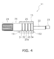
- FIG. 4 is a side view of the shaft 11 in the first embodiment.
- the position of the bearing member 15 is indicated by a two-dot chain line.
- the bearing member 15 has a first end 151 and a second end 152 in the axial direction of the shaft 11.
- the shaft 11 has the connecting part 24, the middle part 26, and the sliding part 25.
- the outer peripheral face of the connecting part 24 is knurled.
- the middle part 26 has a smooth surface.
- the outer peripheral face of the sliding part 25 is a sliding face 25a that slides with respect to the inner peripheral face of the bearing member 15. More precisely, the sliding face 25a is a portion of the outer peripheral face of the shaft 11 that is located between the first end 151 and the second end 152 of the bearing member 15.
- the sliding face 25a generates friction with the inner peripheral face of the bearing member 15, so it is coated with grease.
- a plurality of grooves 31 to 34 are provided to the sliding face 25a.
- FIG. 5 is a detail view of the groove 31. As shown in FIG. 5 , the groove 31 has a V-shaped cross section. The other grooves 32 to 34 have a V-shaped cross section the same as that of the groove 31.
- the grooves 31 to 34 are spaced equidistantly in the axial direction of the shaft 11.
- the grooves 31 to 34 are disposed uniformly from one end of the sliding face 25a to the other in the axial direction of the shaft 11. That is, the distance between the first end 151 and the groove 31, which is the closest to the first end 151 of the bearing member 15 of all the grooves 31 to 34, is equal to the spacing between the grooves 31 to 34. Also, the distance between the second end 152 and the groove 34, which is the closest to the second end 152 of the bearing member 15, is equal to the spacing between the grooves 31 to 34.
- the positions of the grooves 31 to 34 are based on the centers of the grooves 31 to 34 in the axial direction of the shaft 11. In this embodiment, four grooves are provided to the sliding face 25a, but the number of grooves is not limited to four, and there may be three or fewer grooves, or there may be five or more.
- the grooves 31 to 34 are provided to the sliding face 25a of the shaft 11, and therefore, the grease that coats the sliding face 25a accumulates in the grooves 31 to 34. This means that even if the viscosity of the grease on the sliding face should decrease under a high temperature environment and the oil component flows out, the oil component will be resupplied from the grease in the grooves 31 to 34. This improves the heat resistance of the switch 1 even when an inexpensive grease is used.
- relatively inexpensive grease sometimes includes lithium stearate or another such metal soap as a thickener. These metal soaps have molecules in the form of long, slender fibers, and adhere fast to metal surfaces.
- a grease that contains such a metal soap is compressed in the narrow gap between the bearing member 15 and the shaft 11, the molecules tend to become intertwined, making deformation of the grease more difficult. As a result, a problem is that sliding resistance tends to rise under low temperature environments.
- the grooves 31 to 34 provided to the sliding face 25a ensure a space that is wide enough for the grease molecules to move around. Therefore, the grease molecules are less likely to intertwine, and the grease deforms more readily. This allows the cold resistance of the switch 1 to be enhanced even when an inexpensive grease is used.
- the viscosity of a grease is inversely proportional to temperature. That is, the viscosity drops at high temperatures, and rises at low temperatures.
- a problem that occurs with a switch at high temperatures is that the viscosity of the grease decreases and fluidity goes up. When fluidity goes up and the oil component flows off of the sliding face, heat and friction build up in the grease that has lost its oil component, resulting in "seizure,” so that lubrication can no longer be maintained. Therefore, a grease with high viscosity and a high dropping point is favorable for switches used in high temperature environments.
- the plurality of grooves 31 to 34 are provided to the sliding face 25a, grease can be supplied to a wider range of the sliding face 25a.
- the grooves 31 to 34 are disposed uniformly over the sliding face 25a, grease can be supplied more evenly.
- the machining for providing the grooves 31 to 34 is easy. Also, there will be less of a decrease in the strength of the shaft 11. Also, the grooves 31 to 34 extend in the peripheral direction of the shaft 11. Therefore, the machining for providing the grooves 31 to 34 can be easily carried out by cutting or the like.
- the shape of the grooves 31 to 34 of the sliding face 25a is not limited to what was discussed above, and may be modified. Some modification examples of the groove shape will now be given.
- FIG. 6 is a cross section of a groove 131 according to a first modification example.
- the groove 131 according to the first modification example is similar to the groove 31 in the first embodiment in that it extends in the peripheral direction.
- the groove 131 has a pair of side face components 131a and 131b and a bottom face component 131c that links the pair of side face components 131a and 131b.
- the bottom face component 131c has a linear shape.
- heat resistance can be further enhanced by increasing how much grease is held in the groove 131.
- cold resistance can be further enhanced by enlarging the space in which the grease can move around.
- FIG. 7 is a cross section of a groove 231 according to a second modification example.
- the groove 231 according to the second modification example is similar to the groove 31 in the first embodiment in that it extends in the peripheral direction.
- the groove 231 has a U-shaped cross section. That is, in side view, the bottom face of the groove 231 has a curved shape.
- heat resistance can be further enhanced by increasing how much grease is held in the groove 231 compared to a V-shaped groove.
- cold resistance can be further enhanced by enlarging the space in which the grease can move around.
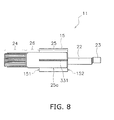
- FIG. 8 is a side view of a groove 331 according to a third modification example.
- the groove 331 according to the third modification example extends in the axial direction of the shaft 11.
- the groove 331 is provided over the entire sliding face 25a in the axial direction of the shaft 11.
- a plurality of grooves extending in the axial direction of the shaft 11 may be disposed spaced apart in the peripheral direction of the shaft 11.
- the grooves extending in the axial direction of the shaft 11 are preferably disposed equidistantly spaced in the peripheral direction of the shaft 11.
- FIG. 9 is a side view of a groove 431 according to a fourth modification example.
- the groove 431 in the fourth modification example extends in a spiral shape.
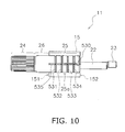
- FIG. 10 is a side view of a groove 530 according to a fifth modification example.
- the groove 530 according to the fifth modification example has grooves 531 to 534 extending in the peripheral direction of the shaft 11, and a groove 535 extending in the axial direction of the shaft 11.
- FIG. 10 only one groove 535 is shown extending in the axial direction of the shaft 11, but the groove 530 according to the fifth modification example may have a plurality of grooves extending in the axial direction of the shaft 11.
- the grooves 331, 431, and 530 according to modification examples 3 to 5 each have a V-shaped cross section, but may instead have a cross section that is other than V-shaped, as in the groove 131 of the first modification example or the groove 231 of the second modification example.
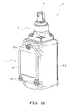
- FIG. 11 is an oblique view of the switch 5 according to the second embodiment
- FIG. 12 is a cross section of the switch 5 according to the second embodiment.
- the switch 5 has a manipulation member 6, a transmission component 7, and a main body component 4.
- the manipulation member 6 is a roller.
- the transmission component 7 transmits the operation of the manipulation member 6 to the main body component 4.
- the main body component 4 is configured the same as the main body component 4 in the first embodiment above. Therefore, components that are the same as in the main body component 4 in the first embodiment will be numbered the same and will not be described in detail again.
- the transmission component 7 has a transmission case 71, a shaft 72, a bearing member 73, and an auxiliary shaft 74.
- the manipulation member 6 is rotatably attached to one end of the shaft 72.
- a hole 72a extending in the axial direction of the shaft 72 is provided to the other end of the shaft 72.
- the shaft 72 is supported by the transmission case 71 via the bearing member 73.
- the bearing member 73 supports the shaft 72 movably in the axial direction of the shaft 72.
- the shaft 72 is supported by the main body case 41 via a first return spring 75.
- the auxiliary shaft 74 is aligned with the axial direction of the shaft 72.
- the auxiliary shaft 74 is disposed concentrically with the shaft 72.
- the auxiliary shaft 74 has a first end 74a and a second end 74b.
- the first end 74a of the auxiliary shaft 74 is disposed inside the hole 72a of the shaft 72.
- the auxiliary shaft 74 is provided movably in the axial direction of the shaft 72.
- the second end 74b of the auxiliary shaft 74 is opposite the manipulation shaft 48.
- a second return spring 76 is disposed between the auxiliary shaft 74 and the shaft 72.
- the second return spring 76 is disposed inside the hole 72a of the shaft 72.
- the manipulation member 6 is located in the neutral position.
- the manipulation member 6 In a state in which no external force is being exerted on the manipulation member 6, the manipulation member 6 is located in the neutral position.
- the switch main body 42 is in the first contact state.
- the shaft 72 moves in the axial direction of the shaft 72 against the elastic force of the first return spring 75.
- the movement of the shaft 72 in the axial direction is transmitted to the auxiliary shaft 74, and the auxiliary shaft 74 moves in the axial direction of the shaft 72. Consequently, the second end 74b of the auxiliary shaft 74 presses on the manipulation shaft 48.
- the switch main body 42 is switched from the first contact state to the second contact state.
- the shaft 72 moves in the reverse direction under the elastic force of the first return spring 75, and the manipulation member 6 returns to the neutral position.
- the switch main body 42 returns from the second contact state to the first contact state when the manipulation shaft 48 moves.
- the shaft 72 according to the second embodiment is similar to the shaft 11 in the first embodiment in that it has a sliding face 72b provided with grooves.
- FIG. 13 is a side view of the shaft 72 in the second embodiment. In FIG. 13 , the position of the bearing member 73 in the neutral position is indicated by a two-dot chain line.
- Grooves 81 to 83 are provided to the sliding face 72b of the shaft 72. In this embodiment, three grooves (81 to 83) are provided to the sliding face 72b.
- the grooves 81 to 83 have a V-shaped cross section.
- the grooves 81 to 83 extend in the peripheral direction of the shaft 72.
- the grooves 81 to 83 are equidistantly spaced, and are disposed uniformly over the sliding face 72b with the bearing member 73.
- the form of the grooves 81 to 83 is not limited to what is shown in FIG. 13 , and may be the same form as that of the grooves according to any of the first to fifth modification examples discussed above.
- the shaft had a sliding face provided with grooves
- the bearing member may instead have a sliding face provided with grooves. That is, as shown in FIGS. 14 to 17 , grooves may be provided to the sliding face of the bearing member 15 (the inner peripheral face of the through-hole 15a).
- a plurality of grooves 91 to 94 extending in the peripheral direction of the bearing member 15 may be provided to the sliding face of the bearing member 15.
- a spiral groove 191 may be provided to the sliding face of the bearing member 15.
- a groove 291 extending in the axial direction of the bearing member 15 may be provided to the sliding face of the bearing member 15.
- groove 390 may be provided to the sliding face of the bearing member 15. The grooves 390 has a plurality of grooves 391 to 394 extending in the peripheral direction of the bearing member 15, and a groove 395 extending in the axial direction of the bearing member 15.
- the number and layout of the grooves in the sliding face of the bearing member 15 are not limited to what is shown in FIGS. 14 to 17 .
- the cross sectional shape of the various grooves of the bearing member 15 is not limited to a V shape, just as with the cross sectional shape of the various grooves of the shaft.
- a limit switch was used as an example, but the present invention may be applied to some switch other than a limit switch.
- a plurality of grooves were disposed equidistantly spaced apart, but may instead be disposed at uneven intervals. In the above embodiments, a plurality of grooves were disposed uniformly over the sliding face, but may instead be disposed unevenly.
Landscapes
- Switches With Compound Operations (AREA)
- Rotary Switch, Piano Key Switch, And Lever Switch (AREA)
Abstract
It is an object of the present invention to provide a switch with which heat resistance and cold resistance can both be increased inexpensively. This switch comprises a bearing member, a shaft, a manipulation member, and a switch main body. The shaft is slidably supported by the bearing member. The manipulation member is linked to the shaft. The switch main body switches a contact according to displacement of the shaft. The shaft or the bearing member includes a sliding face having a groove.
Description
- The present invention relates to a switch.
- There are switches with which the operation of a manipulation member is transmitted through a shaft to a switch main body (see Japanese Laid-Open Patent Application
2000-7131 - It is preferable to use a lubricant with a chemically stable oil composition in order for the heat resistance and cold resistance of the switch both to reach a high level at the same time. For instance, a fluorine oil or silicon oil may be used for this lubricant. These lubricants are extremely expensive, however, and therefore are a factor in driving up the cost of the switch.
- On the other hand, it is exceedingly difficult to achieve high heat resistance and cold resistance at the same time in a switch with inexpensive grease. For example, a grease with good cold resistance will generally have low viscosity, and will therefore tend to ooze out from the sliding face under a high temperature environment. Accordingly, a problem is that the oil component tends to be depleted. Also, since a grease with good heat resistance generally has high viscosity, a high starting torque is required under a low temperature environment. Therefore, poor switch return is among the problems that are encountered.
- It is an object of the present invention to provide a switch with which heat resistance and cold resistance can both be increased inexpensively.
- A switch according to one aspect of the present invention comprises a bearing member, a shaft, a manipulation member, and a switch main body. The shaft is slidably supported by the bearing member. The manipulation member is linked to the shaft. The switch main body switches a contact according to displacement of the shaft. The shaft or the bearing member includes a sliding face having a groove.
- With the switch according to this aspect, grease accumulates in the groove of the sliding face. Therefore, even if the viscosity of the grease on the sliding face should decrease under a high temperature environment and the oil component flows out, the oil component will be resupplied from the grease in the groove. This improves the heat resistance of the switch even when an inexpensive grease is used. Also, under a low temperature environment, the groove ensures a space large enough to allow the grease to move during sliding of the bearing member and the shaft. Accordingly, compared to when the grease is held in a narrow gap between the bearing member and the shaft, deformation of the grease is easier and the sliding resistance can be reduced. This allows cold resistance to be improved even when an inexpensive grease is used. Thus, with the switch according to this aspect, both heat resistance and cold resistance can be improved inexpensively.
- Preferably, the groove has a V-shaped cross section. In this case, the machining to form the groove is easier. Also, there is less of a decrease in the strength of the shaft.
- Preferably, the groove has a cross sectional shape having a pair of side face components and a bottom face component that links the pair of side face components. In this case, heat resistance can be further enhanced because more grease is held in the groove. Also, enlarging the space in which the grease can move further improves cold resistance.
- Preferably, the groove has a U-shaped cross section. In this case, heat resistance can be further enhanced because more grease is held in the groove. Also, enlarging the space in which the grease can move further improves cold resistance.
- Preferably, the groove extends in the peripheral direction of the shaft or the bearing member. In this case, the machining to form the groove is easier.
- Preferably, the sliding face has a plurality of grooves. In this case, grease can be supplied over a wider range of the sliding face.
- Preferably, the plurality of grooves are equidistantly spaced. In this case, grease can be uniformly supplied over a wider range of the sliding face.
- Preferably, the plurality of grooves each extend in the peripheral direction of the shaft or the bearing member. The plurality of grooves are disposed uniformly from one end of the sliding face to the other end in the axial direction of the shaft or the bearing member. In this case, grease can be uniformly supplied over a wider range of the sliding face.
- Preferably, the groove extends in a spiral shape. In this case, the machining to form the groove is easier. Also, grease can be supplied over a wider range of the sliding face.
- Preferably, the manipulation member has a lever member that extends in the radial direction of the shaft. The bearing member rotatably supports the shaft. In this case, heat resistance and cold resistance are better when the shaft slides in a rotational direction with respect to the bearing member.
- Preferably, the bearing member supports the shaft movably in the axial direction of the shaft. In this case, heat resistance and cold resistance are better when the shaft slides in an axial direction with respect to the bearing member.
-
-
FIG. 1 is an oblique view of a switch according to a first embodiment. -
FIG. 2 is a II-II cross section of the switch inFIG. 1 . -
FIG. 3 is a simplified view of the internal configuration of the switch main body. -
FIG. 4 is a side view of the shaft in the first embodiment. -
FIG. 5 is a cross section of the groove of the shaft. -
FIG. 6 is a cross section of the groove according to a first modification example. -
FIG. 7 is a cross section of the groove according to a second modification example. -
FIG. 8 is a side view of the groove according to a third modification example. -
FIG. 9 is a side view of the groove according to a fourth modification example. -
FIG. 10 is a side view of the groove according to a fifth modification example. -
FIG. 11 is an oblique view of the switch according to a second embodiment. -
FIG. 12 is a cross section of the switch according to the second embodiment. -
FIG. 13 is a side view of the shaft in the second embodiment. -
FIG. 14 is a cross section of the bearing member according to another embodiment. -
FIG. 15 is a cross section of a modification example of the bearing member. -
FIG. 16 is a cross section of a modification example of the bearing member. -
FIG. 17 is a cross section of a modification example of the bearing member. - A switch according to an embodiment will now be described through reference to the drawings.
FIG. 1 is an oblique view of theswitch 1 according to a first embodiment.FIG. 2 is a II-II cross section of theswitch 1 inFIG. 1 . Theswitch 1 according to this embodiment is what is known as a limit switch. As shown inFIG. 1 , theswitch 1 has amanipulation member 2, atransmission component 3, and amain body component 4. Thetransmission component 3 has ashaft 11, and is linked to themanipulation member 2 via theshaft 11. Thetransmission component 3 is attached to themain body component 4. - The
manipulation member 2 has alever member 12 and aroller 13. Thelever member 12 is in the form of a rod. Thelever member 12 extends in the radial direction of theshaft 11. Theroller 13 is rotatably attached to one end of thelever member 12. Theshaft 11 is fixed to the other end of thelever member 12. Themanipulation member 2 is provided rotatably around the axis of theshaft 11. Using the position of themanipulation member 2 shown inFIG. 1 as a neutral position, themanipulation member 2 is provided rotatably in a first direction and a second direction from the neutral position. For example, inFIG. 1 , the first direction is clockwise, and the second direction is counter-clockwise. - The
transmission component 3 transmits the operation of themanipulation member 2. As shown inFIG. 2 , thetransmission component 3 has the above-mentionedshaft 11, atransmission case 14, and a bearingmember 15. Theshaft 11 is supported by thetransmission case 14 via the bearingmember 15. Theshaft 11 is slidably supported by the bearingmember 15. Theshaft 11 is made from stainless steel or another such metal, for example. The material of theshaft 11 is not limited to this, however. - The bearing
member 15 is tubular in form. The bearingmember 15 has a through-hole 15a, and theshaft 11 is inserted into the through-hole 15a. The bearingmember 15 rotatably supports theshaft 11. The bearingmember 15 is preferably formed from a sliding material. For instance, the bearingmember 15 may be made from a copper alloy. As an example, the bearingmember 15 is made from a sintered metal. The material of the bearingmember 15 is not limited to these materials, however. - The
shaft 11 has afirst shaft component 21, asecond shaft component 22, and athird shaft component 23. Thefirst shaft component 21, thesecond shaft component 22, and thethird shaft component 23 are aligned in the axial direction of theshaft 11. The outside diameter of thefirst shaft component 21 is larger than the outside diameter of thesecond shaft component 22. Thesecond shaft component 22 is disposed between thefirst shaft component 21 and thethird shaft component 23. The outside diameter of thethird shaft component 23 is smaller than the outside diameter of thesecond shaft component 22. Thefirst shaft component 21 protrudes from thetransmission case 14, and is linked to themanipulation member 2. Thesecond shaft component 22 and thethird shaft component 23 are disposed inside thetransmission case 14. - The
shaft 11 has a connectingpart 24, amiddle part 26, and a slidingpart 25. The connectingpart 24, themiddle part 26, and the slidingpart 25 are provided to thefirst shaft component 21. The connectingpart 24 protrudes from thetransmission case 14. The connectingpart 24 is connected to themanipulation member 2. Themiddle part 26 is located between the connectingpart 24 and the slidingpart 25 in the axial direction of theshaft 11. The gap between theshaft 11 and thetransmission case 14 is sealed off by a sealingmember 16 in themiddle part 26. The slidingpart 25 is disposed inside the through-hole 15a of the bearingmember 15. - The
transmission component 3 has afirst cam 17, asecond cam 18, and aplunger 19. Thefirst cam 17 and thesecond cam 18 are disposed aligned in the axial direction of theshaft 11. Thefirst cam 17 has ahole 17a. Thesecond cam 18 has ahole 18a. Thesecond shaft component 22 is inserted into thehole 17a of thefirst cam 17 and thehole 18a of thesecond cam 18. - The configuration is such that when the
shaft 11 rotates in the first direction around its axis, thefirst cam 17 rotates along with theshaft 11, and thesecond cam 18 freewheels with respect to theshaft 11. When theshaft 11 rotates in the second direction (the opposite of the first direction), thesecond cam 18 rotates along with theshaft 11, and thefirst cam 17 freewheels with respect to theshaft 11. - The
plunger 19 is disposed so that the axis of theplunger 19 is perpendicular to the axis of theshaft 11. Theplunger 19 has afirst end 19a and asecond end 19b in the axial direction of theplunger 19. Thefirst end 19a is disposed opposite thefirst cam 17 and thesecond cam 18. When thefirst cam 17 rotates along with theshaft 11, thefirst cam 17 presses thefirst end 19a in the axial direction of theplunger 19. Similarly, when thesecond cam 18 rotates along with theshaft 11, thesecond cam 18 presses thefirst end 19a in the axial direction of theplunger 19. When thefirst end 19a is pressed by thefirst cam 17 or thesecond cam 18, thesecond end 19b moves in the axial direction of theplunger 19. - A
first return spring 27 is connected to thefirst cam 17 and thesecond cam 18. Thefirst return spring 27 is a torsion coil spring, for example. When thefirst cam 17 rotates in the first direction along with theshaft 11, thefirst return spring 27 presses thefirst cam 17 in the direction of returning thefirst cam 17. When thesecond cam 18 rotates in the second direction along with theshaft 11, thefirst return spring 27 presses thesecond cam 18 in the direction of returning thesecond cam 18. - The
main body component 4 has amain body case 41 and a switchmain body 42. Themain body case 41 houses the switchmain body 42. Themain body case 41 has abase component 43, acover 44, and a sealingmember 45. The switchmain body 42 is disposed inside thebase component 43. A connectinghole 43a is provided to thebase component 43. The connectinghole 43a is disposed opposite the switchmain body 42. Thecover 44 is fixed to thebase component 43 byscrews 46. The space between thecover 44 and thebase component 43 is sealed off by the sealingmember 45. - The operation of the
manipulation member 2 is transmitted through thetransmission component 3 to the switchmain body 42. The switchmain body 42 is fixed to thebase component 43. The switchmain body 42 has aswitch case 47 and amanipulation shaft 48. Themanipulation shaft 48 protrudes from theswitch case 47. Themanipulation shaft 48 is disposed concentrically with theplunger 19. The contact of the switchmain body 42 is switched when themanipulation shaft 48 moves in the axial direction. -
FIG. 3 is a simplified view of the internal configuration of the switchmain body 42. The switchmain body 42 has amovable contact arm 51, a plurality ofstationary contacts 52 to 55, asecond return spring 56, and aleaf spring 59. Themovable contact arm 51 is linked to themanipulation shaft 48 via theleaf spring 59. Themovable contact arm 51 is provided movably in the axial direction of themanipulation shaft 48 according to operation of themanipulation shaft 48. Themovable contact arm 51 has a firstmovable contact 57 and a secondmovable contact 58. The switchmain body 42 switches the state of these contacts (open or closed) according to movement of themanipulation shaft 48. - More precisely, the switch
main body 42 has a firststationary contact 52, a secondstationary contact 53, a thirdstationary contact 54, and a fourthstationary contact 55. Theleaf spring 59 is provided so as to press themovable contact arm 51 in the opposite direction from the movement direction of themanipulation shaft 48, in the axial direction of themanipulation shaft 48. Thesecond return spring 56 presses themanipulation shaft 48 upward inFIG. 3 , so theleaf spring 59 presses themovable contact arm 51 downward inFIG. 3 . That is, thesecond return spring 56 presses themanipulation shaft 48 so that the firstmovable contact 57 and the secondmovable contact 58 come into contact with the thirdstationary contact 54 and the fourthstationary contact 55, respectively. Therefore, in a state in which theplunger 19 is not pressing themanipulation shaft 48, the firstmovable contact 57 and the thirdstationary contact 54 are touching, and the secondmovable contact 58 and the fourthstationary contact 55 are touching (hereinafter this state will be referred to as a "first contact state"). When theplunger 19 presses themanipulation shaft 48 against the elastic force of thesecond return spring 56, theleaf spring 59 inverts and moves themovable contact arm 51 upward inFIG. 3 . Consequently, the firstmovable contact 57 and the secondmovable contact 58 separate from the thirdstationary contact 54 and the fourthstationary contact 55, respectively. The firstmovable contact 57 then touches the firststationary contact 52, the secondmovable contact 58 touches the second stationary contact 53 (hereinafter this state will be referred to as a "second contact state"). - Next, the operation of the
switch 1 will be described. When themanipulation member 2 is in the neutral position shown inFIG. 1 , thefirst cam 17 and thesecond cam 18 are not pressing on thefirst end 19a of theplunger 19. Accordingly, themanipulation shaft 48 is pressed by thesecond return spring 56 so that the firstmovable contact 57 and the secondmovable contact 58 touch the firststationary contact 52 and the secondstationary contact 53, respectively. Consequently, when themanipulation member 2 is in the neutral state, the switchmain body 42 is in the first contact state. - When the
roller 13 of themanipulation member 2 is subjected to an external force, themanipulation member 2 rotates around the axis of theshaft 11. For example, when themanipulation member 2 rotates in the first direction from the neutral position, theshaft 11 rotates in the first direction along with themanipulation member 2. When thefirst cam 17 then rotates in the first direction along with theshaft 11, thefirst cam 17 presses on thefirst end 19a of theplunger 19. Consequently, theplunger 19 moves in the axial direction, and thesecond end 19b of theplunger 19 presses themanipulation shaft 48 against the elastic force of thesecond return spring 56. As a result, the switchmain body 42 is switched from the first contact state to the second contact state. - When the
manipulation member 2 rotates in the second direction from the neutral position, theshaft 11 rotates in the second direction along with themanipulation member 2. Then, thesecond cam 18 rotates in the second direction along with theshaft 11, and thesecond cam 18 presses on thefirst end 19a of theplunger 19. Consequently, theplunger 19 moves in the axial direction, and thesecond end 19b of theplunger 19 presses themanipulation shaft 48 against the elastic force of thesecond return spring 56. As a result, the switchmain body 42 is switched from the first contact state to the second contact state. - When the external force is removed from the
roller 13, the elastic force of thefirst return spring 27 causes theshaft 11 to rotate in the reverse direction, and themanipulation member 2 goes back to the neutral position. Also, the elastic force of thesecond return spring 56 causes themanipulation shaft 48 to move, and the switchmain body 42 returns from the second contact state to the first contact state. - Next, the structure of the
shaft 11 will be described.FIG. 4 is a side view of theshaft 11 in the first embodiment. InFIG. 4 , the position of the bearingmember 15 is indicated by a two-dot chain line. The bearingmember 15 has afirst end 151 and asecond end 152 in the axial direction of theshaft 11. - As discussed above, the
shaft 11 has the connectingpart 24, themiddle part 26, and the slidingpart 25. As shown inFIG. 4 , the outer peripheral face of the connectingpart 24 is knurled. Themiddle part 26 has a smooth surface. The outer peripheral face of the slidingpart 25 is a slidingface 25a that slides with respect to the inner peripheral face of the bearingmember 15. More precisely, the slidingface 25a is a portion of the outer peripheral face of theshaft 11 that is located between thefirst end 151 and thesecond end 152 of the bearingmember 15. The slidingface 25a generates friction with the inner peripheral face of the bearingmember 15, so it is coated with grease. A plurality ofgrooves 31 to 34 are provided to the slidingface 25a. - The
grooves 31 to 34 each extend in the peripheral direction of theshaft 11.FIG. 5 is a detail view of thegroove 31. As shown inFIG. 5 , thegroove 31 has a V-shaped cross section. Theother grooves 32 to 34 have a V-shaped cross section the same as that of thegroove 31. - The
grooves 31 to 34 are spaced equidistantly in the axial direction of theshaft 11. Thegrooves 31 to 34 are disposed uniformly from one end of the slidingface 25a to the other in the axial direction of theshaft 11. That is, the distance between thefirst end 151 and thegroove 31, which is the closest to thefirst end 151 of the bearingmember 15 of all thegrooves 31 to 34, is equal to the spacing between thegrooves 31 to 34. Also, the distance between thesecond end 152 and thegroove 34, which is the closest to thesecond end 152 of the bearingmember 15, is equal to the spacing between thegrooves 31 to 34. The positions of thegrooves 31 to 34 are based on the centers of thegrooves 31 to 34 in the axial direction of theshaft 11. In this embodiment, four grooves are provided to the slidingface 25a, but the number of grooves is not limited to four, and there may be three or fewer grooves, or there may be five or more. - As discussed above, with the
switch 1 in the first embodiment, thegrooves 31 to 34 are provided to the slidingface 25a of theshaft 11, and therefore, the grease that coats the slidingface 25a accumulates in thegrooves 31 to 34. This means that even if the viscosity of the grease on the sliding face should decrease under a high temperature environment and the oil component flows out, the oil component will be resupplied from the grease in thegrooves 31 to 34. This improves the heat resistance of theswitch 1 even when an inexpensive grease is used. - Also, the viscosity of grease generally rises under a low temperature environment. Therefore, a higher torque is necessary to start the switch, and the sliding resistance increases. Moreover, relatively inexpensive grease sometimes includes lithium stearate or another such metal soap as a thickener. These metal soaps have molecules in the form of long, slender fibers, and adhere fast to metal surfaces. However, when a grease that contains such a metal soap is compressed in the narrow gap between the bearing
member 15 and theshaft 11, the molecules tend to become intertwined, making deformation of the grease more difficult. As a result, a problem is that sliding resistance tends to rise under low temperature environments. - With the
switch 1 according to this embodiment, however, thegrooves 31 to 34 provided to the slidingface 25a ensure a space that is wide enough for the grease molecules to move around. Therefore, the grease molecules are less likely to intertwine, and the grease deforms more readily. This allows the cold resistance of theswitch 1 to be enhanced even when an inexpensive grease is used. - In general, the viscosity of a grease is inversely proportional to temperature. That is, the viscosity drops at high temperatures, and rises at low temperatures. There is a "dropping point" that serves as an index of the heat resistance of a grease. The higher is the dropping point, the better the heat resistance. A problem that occurs with a switch at high temperatures is that the viscosity of the grease decreases and fluidity goes up. When fluidity goes up and the oil component flows off of the sliding face, heat and friction build up in the grease that has lost its oil component, resulting in "seizure," so that lubrication can no longer be maintained. Therefore, a grease with high viscosity and a high dropping point is favorable for switches used in high temperature environments.
- Meanwhile, there is a "pour point" that serves as an index of the cold resistance of a grease. The lower is the pour point, the better the cold resistance. A problem that is encountered with switches at low temperatures is that the viscosity of the grease rises and fluidity decreases. When fluidity decreases, there is an increase in sliding resistance, and the switch may end up taking a long time to return. Therefore, unlike grease that is favorable for high temperature environments, a grease that has low viscosity and a low pour point is favorable for switches used in low temperature environments.
- As discussed above, there is a trade-off between the heat resistance and the cold resistance of a grease, and it is difficult to achieve good heat resistance and cold resistance at the same time in a single type of grease. By contrast, with the
switch 1 according to this embodiment, providing thegrooves 31 to 34 to the slidingface 25a allows heat resistance and cold resistance requirements to be satisfied at the same time with a single type of grease. Consequently, both heat resistance and cold resistance can be improved inexpensively. - Since the plurality of
grooves 31 to 34 are provided to the slidingface 25a, grease can be supplied to a wider range of the slidingface 25a. In particular, since thegrooves 31 to 34 are disposed uniformly over the slidingface 25a, grease can be supplied more evenly. - Because the
grooves 31 to 34 have a V-shaped cross section, the machining for providing thegrooves 31 to 34 is easy. Also, there will be less of a decrease in the strength of theshaft 11. Also, thegrooves 31 to 34 extend in the peripheral direction of theshaft 11. Therefore, the machining for providing thegrooves 31 to 34 can be easily carried out by cutting or the like. - The shape of the
grooves 31 to 34 of the slidingface 25a is not limited to what was discussed above, and may be modified. Some modification examples of the groove shape will now be given. -
FIG. 6 is a cross section of agroove 131 according to a first modification example. Thegroove 131 according to the first modification example is similar to thegroove 31 in the first embodiment in that it extends in the peripheral direction. However, as shown inFIG. 6 , thegroove 131 has a pair ofside face components bottom face component 131c that links the pair ofside face components bottom face component 131c has a linear shape. In this case, heat resistance can be further enhanced by increasing how much grease is held in thegroove 131. Also, cold resistance can be further enhanced by enlarging the space in which the grease can move around. -
FIG. 7 is a cross section of agroove 231 according to a second modification example. Thegroove 231 according to the second modification example is similar to thegroove 31 in the first embodiment in that it extends in the peripheral direction. However, as shown inFIG. 7 , thegroove 231 has a U-shaped cross section. That is, in side view, the bottom face of thegroove 231 has a curved shape. In this case, heat resistance can be further enhanced by increasing how much grease is held in thegroove 231 compared to a V-shaped groove. Also, cold resistance can be further enhanced by enlarging the space in which the grease can move around. Furthermore, there will be less of a decrease in strength because there are no corners in thegroove 231. -
FIG. 8 is a side view of agroove 331 according to a third modification example. Thegroove 331 according to the third modification example extends in the axial direction of theshaft 11. Thegroove 331 is provided over the entire slidingface 25a in the axial direction of theshaft 11. InFIG. 8 only onegroove 331 is shown, but instead of thegroove 331, a plurality of grooves extending in the axial direction of theshaft 11 may be disposed spaced apart in the peripheral direction of theshaft 11. In this case, the grooves extending in the axial direction of theshaft 11 are preferably disposed equidistantly spaced in the peripheral direction of theshaft 11. -
FIG. 9 is a side view of agroove 431 according to a fourth modification example. Thegroove 431 in the fourth modification example extends in a spiral shape. -
FIG. 10 is a side view of agroove 530 according to a fifth modification example. Thegroove 530 according to the fifth modification example hasgrooves 531 to 534 extending in the peripheral direction of theshaft 11, and agroove 535 extending in the axial direction of theshaft 11. InFIG. 10 , only onegroove 535 is shown extending in the axial direction of theshaft 11, but thegroove 530 according to the fifth modification example may have a plurality of grooves extending in the axial direction of theshaft 11. - The
grooves groove 131 of the first modification example or thegroove 231 of the second modification example. - Next, a
switch 5 according to a second embodiment will be described.FIG. 11 is an oblique view of theswitch 5 according to the second embodiment, andFIG. 12 is a cross section of theswitch 5 according to the second embodiment. Theswitch 5 has amanipulation member 6, atransmission component 7, and amain body component 4. Themanipulation member 6 is a roller. Thetransmission component 7 transmits the operation of themanipulation member 6 to themain body component 4. Themain body component 4 is configured the same as themain body component 4 in the first embodiment above. Therefore, components that are the same as in themain body component 4 in the first embodiment will be numbered the same and will not be described in detail again. - The
transmission component 7 has atransmission case 71, ashaft 72, a bearingmember 73, and anauxiliary shaft 74. Themanipulation member 6 is rotatably attached to one end of theshaft 72. Ahole 72a extending in the axial direction of theshaft 72 is provided to the other end of theshaft 72. Theshaft 72 is supported by thetransmission case 71 via the bearingmember 73. The bearingmember 73 supports theshaft 72 movably in the axial direction of theshaft 72. Theshaft 72 is supported by themain body case 41 via afirst return spring 75. - The
auxiliary shaft 74 is aligned with the axial direction of theshaft 72. Theauxiliary shaft 74 is disposed concentrically with theshaft 72. Theauxiliary shaft 74 has afirst end 74a and asecond end 74b. Thefirst end 74a of theauxiliary shaft 74 is disposed inside thehole 72a of theshaft 72. Theauxiliary shaft 74 is provided movably in the axial direction of theshaft 72. Thesecond end 74b of theauxiliary shaft 74 is opposite themanipulation shaft 48. Asecond return spring 76 is disposed between theauxiliary shaft 74 and theshaft 72. Thesecond return spring 76 is disposed inside thehole 72a of theshaft 72. - In
FIGS. 11 and12 , themanipulation member 6 is located in the neutral position. In a state in which no external force is being exerted on themanipulation member 6, themanipulation member 6 is located in the neutral position. In this case, the switchmain body 42 is in the first contact state. When an external force is exerted on themanipulation member 6, theshaft 72 moves in the axial direction of theshaft 72 against the elastic force of thefirst return spring 75. The movement of theshaft 72 in the axial direction is transmitted to theauxiliary shaft 74, and theauxiliary shaft 74 moves in the axial direction of theshaft 72. Consequently, thesecond end 74b of theauxiliary shaft 74 presses on themanipulation shaft 48. As a result, the switchmain body 42 is switched from the first contact state to the second contact state. - When the external force on the
manipulation member 6 is released, theshaft 72 moves in the reverse direction under the elastic force of thefirst return spring 75, and themanipulation member 6 returns to the neutral position. Just as in the first embodiment above, the switchmain body 42 returns from the second contact state to the first contact state when themanipulation shaft 48 moves. - The
shaft 72 according to the second embodiment is similar to theshaft 11 in the first embodiment in that it has a slidingface 72b provided with grooves.FIG. 13 is a side view of theshaft 72 in the second embodiment. InFIG. 13 , the position of the bearingmember 73 in the neutral position is indicated by a two-dot chain line.Grooves 81 to 83 are provided to the slidingface 72b of theshaft 72. In this embodiment, three grooves (81 to 83) are provided to the slidingface 72b. Thegrooves 81 to 83 have a V-shaped cross section. Thegrooves 81 to 83 extend in the peripheral direction of theshaft 72. Thegrooves 81 to 83 are equidistantly spaced, and are disposed uniformly over the slidingface 72b with the bearingmember 73. - The form of the
grooves 81 to 83 is not limited to what is shown inFIG. 13 , and may be the same form as that of the grooves according to any of the first to fifth modification examples discussed above. - Embodiments of the present invention were described above, but the present invention is not limited to or by these embodiments, and various modifications are possible without departing from the gist of the invention.
- In the above embodiments, the shaft had a sliding face provided with grooves, but the bearing member may instead have a sliding face provided with grooves. That is, as shown in
FIGS. 14 to 17 , grooves may be provided to the sliding face of the bearing member 15 (the inner peripheral face of the through-hole 15a). - As shown in
FIG. 14 , for example, a plurality ofgrooves 91 to 94 extending in the peripheral direction of the bearingmember 15 may be provided to the sliding face of the bearingmember 15. Alternatively, as shown inFIG. 15 , aspiral groove 191 may be provided to the sliding face of the bearingmember 15. Alternatively, as shown inFIG. 16 , agroove 291 extending in the axial direction of the bearingmember 15 may be provided to the sliding face of the bearingmember 15. Alternatively, as shown inFIG. 17 ,groove 390 may be provided to the sliding face of the bearingmember 15. Thegrooves 390 has a plurality ofgrooves 391 to 394 extending in the peripheral direction of the bearingmember 15, and agroove 395 extending in the axial direction of the bearingmember 15. - Just as with the grooves in the sliding face of the shaft discussed above, the number and layout of the grooves in the sliding face of the bearing
member 15 are not limited to what is shown inFIGS. 14 to 17 . Also, the cross sectional shape of the various grooves of the bearingmember 15 is not limited to a V shape, just as with the cross sectional shape of the various grooves of the shaft. - In the above embodiments, a limit switch was used as an example, but the present invention may be applied to some switch other than a limit switch.
- In the above embodiments, a plurality of grooves were disposed equidistantly spaced apart, but may instead be disposed at uneven intervals. In the above embodiments, a plurality of grooves were disposed uniformly over the sliding face, but may instead be disposed unevenly.
Claims (11)
- A switch, comprising:a bearing member;a shaft slidably supported by the bearing member;a manipulation member linked to the shaft; anda switch main body configured to switch a contact according to a displacement of the shaft,wherein the shaft or the bearing member includes a sliding face having a groove.
- The switch according to Claim 1,
wherein the groove has a V-shaped cross-section. - The switch according to Claim 1,
wherein the groove has a cross-sectional shape having a pair of side face components and a bottom face component that links the pair of side face components. - The switch according to Claim 1,
wherein the groove has a LT-shaped cross-section. - The switch according to any of Claims 1 to 4,
wherein the groove extends in a peripheral direction of the shaft or the bearing member. - The switch according to any of Claims 1 to 5,
wherein the sliding face has a plurality of grooves. - The switch according to Claim 6,
wherein the plurality of grooves are equidistantly spaced. - The switch according to Claim 6,
wherein the plurality of grooves each extend in the peripheral direction of the shaft or the bearing member, and
the plurality of grooves are disposed uniformly from one end of the sliding face to the other end of the sliding face in an axial direction of the shaft or the bearing member. - The switch according to any of Claims 1 to 4,
wherein the groove extends in a spiral shape. - The switch according to any of Claims 1 to 9,
wherein the manipulation member has a lever member extending in a radial direction of the shaft, and
the bearing member rotatably supports the shaft. - The switch according to any of Claims 1 to 9,
wherein the bearing member supports the shaft movably in the axial direction of the shaft.
Applications Claiming Priority (1)
| Application Number | Priority Date | Filing Date | Title |
|---|---|---|---|
| JP2014011587A JP2015138762A (en) | 2014-01-24 | 2014-01-24 | switch |
Publications (1)
| Publication Number | Publication Date |
|---|---|
| EP2899733A1 true EP2899733A1 (en) | 2015-07-29 |
Family
ID=52146418
Family Applications (1)
| Application Number | Title | Priority Date | Filing Date |
|---|---|---|---|
| EP15150346.3A Withdrawn EP2899733A1 (en) | 2014-01-24 | 2015-01-07 | Switch |
Country Status (4)
| Country | Link |
|---|---|
| US (1) | US20150213977A1 (en) |
| EP (1) | EP2899733A1 (en) |
| JP (1) | JP2015138762A (en) |
| CN (2) | CN204516615U (en) |
Families Citing this family (5)
| Publication number | Priority date | Publication date | Assignee | Title |
|---|---|---|---|---|
| JP2015138762A (en) * | 2014-01-24 | 2015-07-30 | オムロン株式会社 | switch |
| JP6854665B2 (en) * | 2017-02-21 | 2021-04-07 | アズビル株式会社 | How to manufacture limit switches |
| JP6866864B2 (en) * | 2018-03-14 | 2021-04-28 | オムロン株式会社 | Limit switch |
| US12224134B2 (en) * | 2020-08-05 | 2025-02-11 | Tokyo Cosmos Electric Co., Ltd. | Rotary electric component |
| JP2024128808A (en) * | 2023-03-10 | 2024-09-24 | オムロン株式会社 | Limit switch |
Citations (4)
| Publication number | Priority date | Publication date | Assignee | Title |
|---|---|---|---|---|
| DE3413452A1 (en) * | 1984-04-10 | 1985-10-17 | Barlian, Reinhold, Dipl.-Ing.(FH), 6990 Bad Mergentheim | Momentary-contact limit switch |
| EP0438321A2 (en) * | 1990-01-19 | 1991-07-24 | Omron Corporation | A limit switch and a method for manufacture of a rotary shaft for the limit switch |
| JPH0822743A (en) * | 1994-07-07 | 1996-01-23 | Omron Corp | Rotary limit switch |
| JP2000007131A (en) | 1998-06-25 | 2000-01-11 | Daifuku Co Ltd | Roller structure |
Family Cites Families (4)
| Publication number | Priority date | Publication date | Assignee | Title |
|---|---|---|---|---|
| JP2899723B2 (en) * | 1990-09-10 | 1999-06-02 | オムロン株式会社 | Method of manufacturing limit switch rotating shaft |
| JPH058834U (en) * | 1991-07-17 | 1993-02-05 | オムロン株式会社 | Movable plunger device of limit switch |
| JP2006258968A (en) * | 2005-03-15 | 2006-09-28 | Canon Finetech Inc | Image reader and image forming apparatus |
| JP2015138762A (en) * | 2014-01-24 | 2015-07-30 | オムロン株式会社 | switch |
-
2014
- 2014-01-24 JP JP2014011587A patent/JP2015138762A/en active Pending
-
2015
- 2015-01-07 EP EP15150346.3A patent/EP2899733A1/en not_active Withdrawn
- 2015-01-09 US US14/592,918 patent/US20150213977A1/en not_active Abandoned
- 2015-01-12 CN CN201520019582.8U patent/CN204516615U/en not_active Expired - Lifetime
- 2015-01-12 CN CN201510014510.9A patent/CN104810171A/en active Pending
Patent Citations (4)
| Publication number | Priority date | Publication date | Assignee | Title |
|---|---|---|---|---|
| DE3413452A1 (en) * | 1984-04-10 | 1985-10-17 | Barlian, Reinhold, Dipl.-Ing.(FH), 6990 Bad Mergentheim | Momentary-contact limit switch |
| EP0438321A2 (en) * | 1990-01-19 | 1991-07-24 | Omron Corporation | A limit switch and a method for manufacture of a rotary shaft for the limit switch |
| JPH0822743A (en) * | 1994-07-07 | 1996-01-23 | Omron Corp | Rotary limit switch |
| JP2000007131A (en) | 1998-06-25 | 2000-01-11 | Daifuku Co Ltd | Roller structure |
Also Published As
| Publication number | Publication date |
|---|---|
| JP2015138762A (en) | 2015-07-30 |
| CN104810171A (en) | 2015-07-29 |
| CN204516615U (en) | 2015-07-29 |
| US20150213977A1 (en) | 2015-07-30 |
Similar Documents
| Publication | Publication Date | Title |
|---|---|---|
| EP2899733A1 (en) | Switch | |
| JP5354134B2 (en) | Sliding member | |
| JP6644447B2 (en) | Flat type wave gear device | |
| JP5267756B1 (en) | Sliding member and bearing | |
| CN102434585B (en) | Linear bearing sliding mechanism | |
| CN104163195A (en) | Rack guide unit and steering system including same | |
| JP2010133431A (en) | Electric actuator | |
| US9299512B2 (en) | Device for switching and controlling electrical apparatuses | |
| JP5273790B2 (en) | Electric actuator sliding guide mechanism and electric actuator | |
| CN203685860U (en) | Flexible linear bearing | |
| JP2017180665A (en) | Ball Screw | |
| EP2467267B1 (en) | Switching mechanism for a writing instrument | |
| JP5244736B2 (en) | Lubrication structure of fluid pressure cylinder | |
| CN105917138A (en) | Linear electro-mechanical actuator | |
| JP6900389B2 (en) | Sintered oil-impregnated bearing | |
| CN102777596B (en) | Self-locking device of gears of speed changer | |
| CN202732731U (en) | Axial sliding mechanism | |
| JP2010266016A (en) | Linear motion device | |
| CN202001595U (en) | Automobile shift fork shaft component structure | |
| JP3179294U (en) | Fluid spring | |
| JP2014080991A (en) | Reduction gear, and electric power steering device | |
| CN217814909U (en) | High smooth and easy performance gearbox assembly of shifting | |
| JP4843345B2 (en) | Sintered machine parts | |
| CN202937635U (en) | Self-lubricating linear bearing | |
| CN110506172A (en) | For rotating the position return mechanism, transmission internal control mechanism and gearbox of alternative pack |
Legal Events
| Date | Code | Title | Description |
|---|---|---|---|
| PUAI | Public reference made under article 153(3) epc to a published international application that has entered the european phase |
Free format text: ORIGINAL CODE: 0009012 |
|
| 17P | Request for examination filed |
Effective date: 20150107 |
|
| AK | Designated contracting states |
Kind code of ref document: A1 Designated state(s): AL AT BE BG CH CY CZ DE DK EE ES FI FR GB GR HR HU IE IS IT LI LT LU LV MC MK MT NL NO PL PT RO RS SE SI SK SM TR |
|
| AX | Request for extension of the european patent |
Extension state: BA ME |
|
| STAA | Information on the status of an ep patent application or granted ep patent |
Free format text: STATUS: THE APPLICATION IS DEEMED TO BE WITHDRAWN |
|
| 18D | Application deemed to be withdrawn |
Effective date: 20160130 |