EP2899611A1 - Electronic device, method, and program for supporting touch panel operation - Google Patents
Electronic device, method, and program for supporting touch panel operation Download PDFInfo
- Publication number
- EP2899611A1 EP2899611A1 EP15152301.6A EP15152301A EP2899611A1 EP 2899611 A1 EP2899611 A1 EP 2899611A1 EP 15152301 A EP15152301 A EP 15152301A EP 2899611 A1 EP2899611 A1 EP 2899611A1
- Authority
- EP
- European Patent Office
- Prior art keywords
- line
- coordinates
- section
- correction
- sight
- Prior art date
- Legal status (The legal status is an assumption and is not a legal conclusion. Google has not performed a legal analysis and makes no representation as to the accuracy of the status listed.)
- Granted
Links
Images




Classifications
-
- G—PHYSICS
- G06—COMPUTING OR CALCULATING; COUNTING
- G06F—ELECTRIC DIGITAL DATA PROCESSING
- G06F3/00—Input arrangements for transferring data to be processed into a form capable of being handled by the computer; Output arrangements for transferring data from processing unit to output unit, e.g. interface arrangements
- G06F3/01—Input arrangements or combined input and output arrangements for interaction between user and computer
- G06F3/03—Arrangements for converting the position or the displacement of a member into a coded form
- G06F3/041—Digitisers, e.g. for touch screens or touch pads, characterised by the transducing means
- G06F3/0416—Control or interface arrangements specially adapted for digitisers
- G06F3/0418—Control or interface arrangements specially adapted for digitisers for error correction or compensation, e.g. based on parallax, calibration or alignment
-
- G—PHYSICS
- G06—COMPUTING OR CALCULATING; COUNTING
- G06F—ELECTRIC DIGITAL DATA PROCESSING
- G06F3/00—Input arrangements for transferring data to be processed into a form capable of being handled by the computer; Output arrangements for transferring data from processing unit to output unit, e.g. interface arrangements
- G06F3/01—Input arrangements or combined input and output arrangements for interaction between user and computer
- G06F3/011—Arrangements for interaction with the human body, e.g. for user immersion in virtual reality
- G06F3/013—Eye tracking input arrangements
-
- G—PHYSICS
- G06—COMPUTING OR CALCULATING; COUNTING
- G06F—ELECTRIC DIGITAL DATA PROCESSING
- G06F3/00—Input arrangements for transferring data to be processed into a form capable of being handled by the computer; Output arrangements for transferring data from processing unit to output unit, e.g. interface arrangements
- G06F3/01—Input arrangements or combined input and output arrangements for interaction between user and computer
- G06F3/03—Arrangements for converting the position or the displacement of a member into a coded form
- G06F3/041—Digitisers, e.g. for touch screens or touch pads, characterised by the transducing means
- G06F3/0412—Digitisers structurally integrated in a display
Definitions
- the present disclosure relates to an electronic device, a method, and a program for supporting touch panel operation.
- a typical electronic device is provided with a touch panel by which instructions on a graphical user interface (hereinafter also referred as "GUI") of a display section are given by touch input.
- GUI graphical user interface
- operation mistakes sometimes occur in which a user mistakenly touch input on a different place from where the user intended to do so. If an operation mistake occurs, it becomes necessary to cancel the instruction, and to perform correct touch input once again.
- a typical electronic device is capable of displaying with an expanded part of a software keyboard that corresponds to a line of sight.
- the part to be displayed is expanded by the line of sight so that information to be displayed is reduced.
- An electronic device includes a touch panel, a line-of-sight detection section, a line-of-sight correction area calculation section, and an operation coordinate line-of-sight correction section.
- the touch panel is configured to detect the coordinates of an operation point of touch input by a user.
- the line-of-sight detection section is configured to calculate the coordinates of a gaze point on the touch panel at which the line of sight of the user was directed in a specific time range starting at a time point of the touch input on the touch panel by the user.
- the line-of-sight correction area calculation section is configured to calculate a line-of-sight correction area in a specific range from the coordinates of the gaze point, calculated by the line-of-sight detection section, on the touch panel.
- the operation coordinate line-of-sight correction section is configured to change the coordinates of the operation point to the coordinates of the gaze point if the coordinates of the operation point are within the line-of-sight correction area calculated by the line-of-sight correction area calculation section, wherein the operation coordinate line-of-sight correction section is blocked to change the coordinates of the operation point if the coordinates of the operation point are not within the line-of-sight correction area.
- a method of supporting operation includes: (i) detecting, via a touch panel, coordinates of an operation point of touch input by a user; (ii) calculating, via a line-of-sight detection section, coordinates of a gaze point on the touch panel at which a line of sight of the user is directed in a specific time range starting at a time point of the touch input on the touch panel by the user; (iii) calculating, via a line-of-sight correction area calculation section, a line-of-sight correction area in a specific range from the coordinates of the gaze point, calculated by the line-of-sight detection section, on the touch panel; and (iv) changing, via an operation coordinate line-of-sight correction section, the coordinates of the operation point to the coordinates of the gaze point if the coordinates of the operation point are within the line-of-sight correction area calculated by the line-of-sight correction area calculation section, and not changing the coordinates of the operation point if the coordinates of
- a non-transitory computer-readable recording medium stores an operation support program executable by a computer.
- the operation support program includes first to fourth program codes.
- the first program code causes the computer to detect coordinates of a touch input operation point on a touch panel by a user.
- the second program code causes the computer to calculate coordinates of a gaze point on the touch panel at which a line of sight of the user is directed in a specific time range starting at a time point of the touch input on the touch panel by the user.
- the third program code causes the computer to calculate a line-of-sight correction area in a specific range from the coordinates of the gaze point, calculated by the second program code, on the touch panel.
- the fourth program code causes the computer to change the coordinates of the operation point to the coordinates of the gaze point if the coordinates of the operation point are within the line-of-sight correction area calculated by the third program code, and not to change the coordinates of the operation point if the coordinates of the operation point are not within the line-of-sight correction area.
- An image forming apparatus 1 is an example of an electronic device according to an embodiment of the present disclosure.
- an image processing section 11, a document reading section 12, a document feeding section 13, a conveying section 14, a network transmission and reception section 15, an operation panel section 16, an image forming section 17, a timer section 18, a storage section 19, and a line-of-sight detection section 20 are connected to a control section 10. Operation of each section is controlled by the control section 10.
- the control section 10 is an information processing device, such as a GPP (General Purpose Processor), a CPU (Central Processing Unit), an MPU (Micro Processing Unit), a DSP (Digital Signal Processor), a GPU (Graphics Processing Unit), an ASIC (Application Specific Integrated Circuit), or the like.
- GPP General Purpose Processor
- CPU Central Processing Unit
- MPU Micro Processing Unit
- DSP Digital Signal Processor
- GPU Graphics Processing Unit
- ASIC Application Specific Integrated Circuit
- the control section 10 is configured to read a control program stored in a ROM (Read Only Memory) or a HDD (Hard Disk Drive) in the storage section 19, and to expand and to execute the control program in a RAM (Random Access Memory) so as to operate each section of the functional blocks described later. Also, the control section 10 is configured to control the overall apparatus based on instruction information input from an external terminal, or the operation panel section 16.
- ROM Read Only Memory
- HDD Hard Disk Drive
- RAM Random Access Memory
- the image processing section 11 is a control operation device, such as a DSP (Digital Signal Processor), a GPU (Graphics Processing Unit), or the like.
- the image processing section 11 is a device that is configured to perform image processing on image data, and to perform various kinds of image processing, for example, expansion/contraction, density adjustment, gray scale adjustment, image improvement, and the like.
- the image processing section 11 is configured to store an image read by the document reading section 12 into the storage section 19 as print data. At this time, the image processing section 11 is capable of converting print data into a format, such as PDF, TIFF, or the like for each file.
- the document reading section 12 is a scanner that is configured to read a set document.
- the document feeding section 13 is a device that is configured to convey a document that is read by the document reading section 12.
- the conveying section 14 is configured to convey recording paper from a paper feeding cassette, then image forming is performed on the paper by the image forming section 17, and after that, the paper is conveyed to a stack tray.
- the network transmission and reception section 15 is a network connecting device including a LAN board, a radio transmitter/receiver, and the like for connecting to an external network, such as a LAN, a wireless LAN, a WAN, a mobile phone network, or the like.
- the network transmission and reception section 15 is configured to transmit and to receive data through a data communication line, and to transmit and to receive an audio signal through a voice telephone line.
- the operation panel section 16 includes a touch panel 60, a button section 61, and a display section 62.
- the touch panel 60 is a touch input device of an electrostatic capacitance method, a resistive film method, ultrasonic detecting method, or the like for obtaining an instruction, such as coordinates, and the like, at which a user performed operation by pressing a finger (hereinafter referred to as "touch input"). Also, the touch panel 60 may be configured integrally with the display section 62.
- the touch panel 60 obtains user's various instructions through GUI (Graphical User Interface), or the like. Specifically, the touch panel 60 is configured to detect the coordinates of touch input by the user as an operation point. The touch panel 60 may detect that the operation point falls on coordinates corresponding to the coordinates on the display section 62 at this time.
- GUI Graphic User Interface
- the touch panel 60 may detect coordinates that are input by a pen point, such as a dedicated pen, or the like. Also, the touch panel 60 may detect pressing force applied by the user. Also, if the touch panel 60 is of electrostatic capacitance method, an ultrasonic method, or the like, the touch panel 60 may detect coordinates on the display section 62 as an operation point even if untouched by the user's finger. In this case, the touch panel 60 may detect a distance from the display section 62.
- the button section 61 is an input device including a mechanical switch, an electrostatic capacitance switch, or the like.
- the button section 61 includes a start key, a numeric keypad, a button for changing an operation mode of a copy, a scanner, facsimile transmission/reception, and the like, and a button obtaining an instruction related to print/transmission/reception, and the like, of a selected document.
- the display section 62 is a flat display panel, such as an LCD (Liquid Crystal Display), an OELD (Organic Electro-Luminescence Display), an FED (Field Emission Display), or the like, or is a display device, such as a projector, a status display LED, or the like.
- the display section 62 displays at least one item, in particular, at least one and preferably various operation screens.
- the display section 62 is preferably also capable of displaying various images of GUI. Also, the display section 62 is preferably capable of displaying a software keyboard for a user to input characters, and the like on the touch panel 60. The display section 62 is preferably also capable of display corresponding to the coordinates of an operation point that was changed or not changed by the operation coordinate line-of-sight correction section described later at this time. In this regard, the display section 62 is capable of displaying a preview image, or the like that is stored in the storage section 19.
- the timer section 18 is a time acquisition device, such as a CPU internal clock, a real-time clock, a GPS (Global Positioning System) receiver, an NTP client, or the like.
- the timer section 18 is capable of obtaining real-time clock information having less error.
- the timer section 18 is capable of setting a timer that generates an interrupt, or the like after the elapse of a set time period.
- the image forming section 17 forms an image on recording paper from data that is stored in the storage section 19, read by the document reading section 12, or obtained from an external terminal by an output instruction of a user.
- the storage section 19 is a semiconductor memory, such as a ROM, a RAM or the like, or a storage device using a recording medium, such as an HDD, or the like.
- the ROM or the HDD in the storage section 19 stores a control program for performing operation control on the image forming apparatus 1.
- the storage section 19 stores the setting of user accounts.
- the storage section 19 may include an area, such as a document box for each user, and the like.
- the line-of-sight detection section 20 is a line-of-sight detection device including a plurality of cameras, a DSP, and the like, for example.
- FIG. 2 illustrates an example of an outer view of the operation panel section 16, and the line-of-sight detection section 20 of the image forming apparatus 1.
- the line-of-sight detection section 20 detects, for example a user's face and eyes from the captured image data, and further calculates a line of sight in a three-dimensional vector format, or the like.
- the line-of-sight detection section 20 calculates the coordinates (hereinafter referred to as "gaze point coordinates") of an intersection point between the user's line of sight and the touch panel 60, and sets the coordinates in the gaze point.
- the line-of-sight detection section 20 calculates the average values of gaze point coordinates, or the coordinates having the longest gaze time as the coordinates of a gaze point 220 in a time range 210 before and after a time point of touch input by the user on the touch panel 60.
- the line-of-sight detection section 20 may calculate the value of a gaze probability, or the like that is a calculation probability of a gaze point from a gaze time of each gaze point coordinates, a movement vector of the gaze point coordinates, the variance of gaze point coordinates, and the like.
- the time range is set to a shorter value than a time period during touch input before and after the target touch input.
- the touch input intervals have differences among individuals. Accordingly, the average value of the intervals of touch input is measured when a user uses the operation panel section 16, and a time range for each user may be determined based on the measured value.
- the time range may be the average value of touch input intervals, or may be a value produced by dividing the average value by a certain value.
- the line-of-sight detection section 20 is disposed in the operation panel section 16.
- the line-of-sight detection section 20 is disposed at an end of the operation panel section 16.
- the line-of-sight detection section 20 may be disposed on the face of the operation panel section 16, or may be disposed in the operation panel section 16.
- the line-of-sight detection section 20 may be disposed at a position away from the operation panel section 16.
- the line-of-sight detection section 20 may be provided with an illumination section that illuminates the user, and the like.
- control section 10 and the image processing section 11 may be formed integrally like a CPU with integrated GPU, a chip-on-module package, or the like.
- control section 10 or the image processing section 11 may include a RAM, a ROM, a flash memory, or the like.
- the image forming apparatus 1 may include a FAX transmission/reception section that performs facsimile transmission and reception.
- the control section 10 of the image forming apparatus 1 includes a line-of-sight correction area calculation section 100, an operation coordinate line-of-sight correction section 110, and a line-of-sight correction time/area modification section 130.
- the storage section 19 stores an operation point 200, the time range 210, the gaze point 220, a line-of-sight correction area 230, and a line-of-sight correction range 240.
- the line-of-sight correction area calculation section 100 calculates the coordinates of the line-of-sight correction area 230 from the coordinates of the gaze point 220 on the touch panel 60, which was calculated by the line-of-sight detection section 20, and the line-of-sight correction range 240, and stores the coordinates into the storage section 19.
- the line-of-sight correction area calculation section 100 calculates, for example coordinates in the line-of-sight correction range 240 as the line-of-sight correction area 230 with the gaze point 220 as center coordinates.
- the operation coordinate line-of-sight correction section 110 changes the coordinates of the operation point 200 based on the line-of-sight correction area 230 calculated by the line-of-sight correction area calculation section 100. If the operation point 200 is in the line-of-sight correction area 230, the operation coordinate line-of-sight correction section 110 changes the coordinates of the operation point 200 to the coordinates of the gaze point 220. Also, if the operation point 200 is not within the line-of-sight correction area 230, the operation coordinate line-of-sight correction section 110 does not change the coordinates of the operation point 200.
- the operation coordinates line-of-sight correction section 110 calls each processing of GUI after correcting these coordinates.
- the operation coordinate line-of-sight correction section 110 may perform processing so as not to change the coordinates of the operation point 200 of the new touch input corresponding to the correction of the display again.
- the line-of-sight correction time/area modification section 130 modifies the time range 210, and the range set by the line-of-sight correction area 230.
- the line-of-sight correction time/area modification section 130 detects correction of a display of the GUI input character by the user. If the line-of-sight correction time/area modification section 130 detects correction of the display, the line-of-sight correction time/area modification section 130 corrects this.
- the line-of-sight correction time/area modification section 130 changes the time range 210 from the set value at this time, or changes the extent or the shape of the line-of-sight correction area 230.
- the operation point 200 is the data of the coordinates of the operation point of touch input by the user, which was detected by the touch panel 60.
- the operation point 200 may be provided with the setting of the display coordinates on the screen of the display section 62.
- the operation point 200 may include the data on the order of pressing, or the touch order of multi-touch, the direction and acceleration of movement, and the like.
- the time range 210 is data that specifies a range of a time (period) during which the line-of-sight detection section 20 calculates the coordinates of the gaze point 220.
- a range of about a few seconds to a few seconds which is a time period between a calculation start point in time, and a calculation end point before and after a time point of the touch input on the touch panel 60, in the time range 210.
- the gaze point 220 is data of the coordinates of the gaze point on the touch panel 60 to which a line of sight of a user is directed, which was calculated by the line-of-sight detection section 20.
- the coordinates allowed to be compared with the operation point 200, such as display coordinates on the screen of the display section 62, or the like is set in the gaze point 220.
- the gaze point 220 may include values, such as a time period during which individual gaze point coordinates are gazed, a movement vector of the gaze point coordinates, variance values of the gaze point coordinates, gaze probability, and the like.
- the line-of-sight correction area 230 is data of the coordinates of the area in which the coordinates of the operation point 200 are changed into by the operation coordinate line-of-sight correction section 110.
- the line-of-sight correction area 230 is calculated by the line-of-sight correction area calculation section 100 using the coordinates of the gaze point 220, and the line-of-sight correction range 240.
- the line-of-sight correction range 240 is data, such as a coordinate group of a specific range for calculating the line-of-sight correction area 230, mathematical expressions, and the like by the line-of-sight correction area calculation section 100.
- the initial values of the coordinate group, and the like of the line-of-sight correction range 240 may be, for example the values in the range having a distance including a few key areas adjacent to the gaze point 220 on the software keyboard. Also, the size and the extent of this range may be modified by the line-of-sight correction time/area modification section 130.
- the line-of-sight correction range 240 may be data for identifying a circle with the gaze point 220 as center, an ellipse, or any shape of the range. Also, in the case where the shape of this range is an ellipse, the range may be set based on the number of keys on the software keyboard horizontally and vertically in a major axis and a minor axis. Also, as the shape of this range, a shape of an area including a plurality of keys on the software keyboard may be specified.
- control section 10 of the image forming apparatus 1 executes the control program stored in the storage section 19 so as to function as the line-of-sight correction area calculation section 100, the operation coordinate line-of-sight correction section 110, and the line-of-sight correction time/area modification section 130.
- each section in the above-described image forming apparatus 1 becomes a hardware resource for executing a method of forming an image according to the present disclosure.
- the line-of-sight correction range 240 having the gaze point 220 pointed by the line of sight as center is calculated as the line-of-sight correction area 230.
- the operation point 200 that was touch input is inside the line-of-sight correction area 230, it is assumed that the gaze point 220 is touched, and the coordinates of the operation point 200 are changed (hereinafter, in this manner, correcting the coordinates of the operation point 200 by a line of sight on a specific condition is referred to as "correct a line-of-sight"). If the operation point 200 is outside the line-of-sight correction area 230, the coordinates of the operation point 200 is not changed, and the operation place is determined to have been touched without change.
- control section 10 mainly executes the program stored in the storage section 19 in collaboration with each section using the hardware resource.
- control section 10 performs line of sight detection start processing as the line-of-sight correction area calculation section 100.
- the control section 10 starts line-of-sight detection by the line-of-sight detection section 20.
- the line-of-sight detection section 20 starts line-of-sight detection, and start calculating a gaze point 220.
- the touch panel 60 performs operation point detection processing.
- the touch panel 60 When the touch panel 60 detects touch input caused by pressing a finger by a user, the touch panel 60 sets the coordinates on the operation point 200 that was touch input, and stores the coordinates into the storage section 19. Also, the touch panel 60 notifies a time point of this touch input to the line-of-sight detection section 20.
- the line-of-sight detection section 20 performs gaze point calculation processing.
- the line-of-sight detection section 20 calculates data of the gaze point coordinates on the touch panel 60 where a user's line of sight is directed in the time range 210 before and after a time point of the touch input.
- the line-of-sight detection section 20 calculates the coordinates of the gaze point 220 from the data of the calculated gaze point coordinates, and stores the data into the storage section 19.
- the line-of-sight detection section 20 notifies that the line-of-sight detection section 20 has calculated the coordinates of the gaze point 220 to the control section 10.
- control section 10 performs line-of-sight correction area calculation processing as the line-of-sight correction area calculation section 100.
- the control section 10 calculates a group of coordinates of the line-of-sight correction range 240 with the gaze point 220 as center, and the like as the line-of-sight correction area 230 by the notification from the line-of-sight detection section 20.
- a line-of-sight correction area 230 is displayed as a circle having a diameter including one to three key images on a software keyboard with the gaze point 220 as center.
- a display field 600 that is an input field of characters, and a software keyboard 610 for inputting characters into the display field 600 are drawn.
- a button 700 is a button that indicates the completion of input.
- the control section 10 determines whether the operation point 200 is positioned inside the line-of-sight correction area 230 or not as the operation coordinate line-of-sight correction section 110.
- the control section 10 determines as "Yes”.
- the control section 10 determines as "No".
- the control section 10 may determine as "No".
- control section 10 causes the processing to proceed to step S106.
- control section 10 causes the processing to proceed to step S107.
- control section 10 If the operation point 200 is positioned inside the line-of-sight correction area 230, the control section 10 performs operation point coordinate change processing as the operation coordinate line-of-sight correction section 110.
- the control section 10 changes the coordinates of the operation point to the coordinates of the gaze point 220. At this time, the control section 10 may not simply change the coordinates of the operation point to the coordinates of the gaze point 220, but may change the coordinates to specific coordinates.
- the specific coordinates may be a center of a key on the software keyboard that includes the gaze point 220, or the like, for example.
- control section 10 performs operation point instruction operation execution processing as the operation coordinate line-of-sight correction section 110.
- the control section 10 notifies the GUI that processing corresponding to the user's touch input is to be executed on the coordinates of the operation point 200 (if the operation point coordinate change processing in step S106 has been performed, the operation point 200 that was changed to the gaze point 220. Also, if the operation point coordinate change processing in step S106 has not been performed, it is the operation point 200 that was touch input).
- the GUI is a software keyboard
- the control section 10 input characters, and the like corresponding to the key at the notified place of the operation point 200 through the GUI, and displays the characters in the input field of the display section 62, or the like.
- control section 10 determines whether there has been a user correction or not as the line-of-sight correction time/area modification section 130.
- the control section 10 determines as "Yes” on the characters, or the like that was input in step S107 if there has been a correction by a user.
- the control section 10 determines as "Yes”. Otherwise, for example, if the user has input the other characters without correction, or has pressed the completion button 700, the control section 10 determines as "No".
- control section 10 causes the processing to proceed to step S109.
- control section 10 terminates the operation coordinate line-of-sight correction processing.
- step S108 if there has been a correction by the user, the control section 10 performs the operation point coordinate change suppression processing as the line-of-sight correction time/area modification section 130.
- the above-described touch input of the other characters is performed based on a key corresponding to the coordinates of the operation point of the touch input at the time of user correction.
- control section 10 performs control with respect to the operation point of touch input of the other characters so as not to perform the operation point coordinate change processing by the operation coordinate line-of-sight correction section 110. That is to say, the control section 10 does not change the coordinates of the operation point 200 of touch input corresponding to the display correction again.
- control section may make the range of the change of the coordinates of the operation point 200 smaller, or may not allow the change at all at the time of this processing.
- control section 10 performs line-of-sight correction time/area modification processing as the line-of-sight correction time/area modification section 130.
- control section 10 it is possible for the control section 10 to change the time range 210 from the set value.
- the control section 10 makes modification to narrow the line-of-sight correction range 240 so that the coordinates of the operation point 200 before the change are not included in the line-of-sight correction range 240. Also, on the contrary, if the coordinates of the gaze point 220 falls on the coordinates of the corrected key, the control section 10 makes modification to widen the line-of-sight correction range 240 so that the coordinates of the operation point 200 are included in the line-of-sight correction range 240.
- An electronic device has the same overall configuration as that of the image forming apparatus 1 according to the first embodiment illustrated in FIG. 1 and FIG. 2 .
- the control section 10 of the image forming apparatus 1 includes a line-of-sight correction area calculation section 100, an operation coordinate line-of-sight correction section 110, an operation correction result information holding section 120, and a line-of-sight correction time/area modification section 130.
- the storage section 19 stores the operation point 200, the time range 210, the gaze point 220, the line-of-sight correction area 230, the line-of-sight correction range 240, and operation correction result information 250.
- the line-of-sight correction area calculation section 100 calculates the coordinates of the line-of-sight correction area 230 from the coordinates of the gaze point 220 calculated by the line-of-sight detection section 20 on the touch panel 60, and the line-of-sight correction range 240, and stores the coordinates into the storage section 19.
- the line-of-sight correction area calculation section 100 calculates, for example the coordinates in the line-of-sight correction range 240 with the gaze point 220 as center coordinates as the line-of-sight correction area 230.
- the line-of-sight correction area calculation section 100 refers to the specific coordinate change values included in the line-of-sight correction range 240, and calculates the line-of-sight correction area 230.
- the operation coordinate line-of-sight correction section 110 is the same as the operation coordinate line-of-sight correction section 110 in the first embodiment.
- the operation correction result information holding section 120 stores the coordinates of the operation point 200, the coordinates of the gaze point 220, and the change result of the coordinates of the operation point 200 by the operation coordinate line-of-sight correction section 110 into the storage section 19 as the operation correction result information 250, and holds the information.
- the operation correction result information holding section 120 may also hold the user's operation history of display correction of characters, and the like as the operation correction result information 250.
- the line-of-sight correction time/area modification section 130 modifies the ranges of the time range 210, and the line-of-sight correction area 230.
- the line-of-sight correction time/area modification section 130 detects the correction of a display, such as characters, and the like of the GUI input by the user after the change of the coordinate of the operation point 200 by the operation coordinate line-of-sight correction section 110.
- the line-of-sight correction time/area modification section 130 displays the correction, that is, the corrected character, on the display section 62.
- the line-of-sight correction time/area modification section 130 changes the time range 210 from the set value, or changes the width or the shape of the line-of-sight correction area 230.
- the line-of-sight correction time/area modification section 130 expands the line-of-sight correction area 230, else if the user's correction matches the display of the operation point 200, the line-of-sight correction time/area modification section 130 contracts the line-of-sight correction area 230, and else if the user's correction matched neither the display of the gaze point 220 nor the display of the operation point 200, the line-of-sight correction time/area modification section 130 refers to the operation correction result information 250, and moves the line-of-sight correction range 240.
- the operation point 200, the time range 110, the gaze point 220, the line-of-sight correction area 230, and the line-of-sight correction range 240 are defined in the same manner as the first embodiment.
- the line-of-sight correction range 240 may include a specific coordinate change value to be used for changing the coordinates, and the like as an offset value, or the like.
- the operation correction result information 250 is data on the change result history, and the like of the coordinates of the operation point 200, the coordinates of the gaze point 220, and the coordinates of the operation point 200 by the operation coordinate line-of-sight correction section 110.
- the operation correction result information 250 is held for a specific retention period or a retention quantity in order to automatically change the line-of-sight correction area 230. It is possible to set a specific time period, for example about a few seconds to a few minutes for this specific retention period. Also, for a specific retention quantity, for example, in the case of a software keyboard, it is possible to set the amount of input data of a specific number of characters, such as one character to tens of characters. In this regard, a necessary amount of operation correction result information 250 may be retained correspondingly to the storage capacity of the storage section 19. Also, the operation correction result information 250 may include information related to the operation history of user's display correction, and the like.
- control section 10 of the image forming apparatus 1 executes the operation support program included in the control program stored in the storage section 19 so as to function as the line-of-sight correction area calculation section 100, the operation coordinate line-of-sight correction section 110, the operation correction result information holding section 120, and the line-of-sight correction time/area modification section 130.
- each section in the above-described image forming apparatus 1 becomes a hardware resource for executing a method of forming an image according to the present disclosure.
- the line-of-sight correction range 240 having the gaze point 220 pointed by the line of sight as center is calculated as the line-of-sight correction area 230.
- the operation point 200 that was touch input is inside the line-of-sight correction area 230, it is assumed that the gaze point 220 is touched, and the coordinates of the operation point 200 are changed (hereinafter, in this manner, correcting the coordinates of the operation point 200 by a line of sight on a specific condition is referred to as "correct a line-of-sight"). If the operation point 200 is outside the line-of-sight correction area 230, the coordinates of the operation point 200 is not changed, and the operation place is determined to be touched without change.
- control section 10 mainly executes the program stored in the storage section 19 in collaboration with each section using the hardware resource.
- steps S1101 to S1106 is the same as the processing in steps S101 to S106 illustrated in FIG. 4 , respectively.
- control section 10 performs operation correction result information storage processing as the operation correction result information holding section 120.
- the control section 10 stores the operation correction result information 250 in the storage section 19 for one character input and for each operation point coordinate change processing.
- the operation correction result information 250 may include the coordinates of the operation point 200, the coordinates of the gaze point 220, and the change result of the coordinates of the operation point 200.
- control section 10 performs operation point instruction operation execution processing as the operation coordinate line-of-sight correction section 110.
- the control section 10 notifies the GUI to execute the processing corresponding to the user's touch input on the coordinates of the operation point 200 (if the operation point coordinate change processing in step S1106 has been performed, the operation point 200 that was changed to the gaze point 220. Also, if the operation point coordinate change processing in step S1106 has not been performed, the operation point 200 that was touch input).
- the control section 10 inputs the characters, or the like corresponding to the key of the place of the notified operation point 200 by the GUI, and displays the characters, or the like in the input field or the like of the display section 62.
- control section 10 determines whether there has been a user correction as the line-of-sight correction time/area modification section 130. If there has been a correction by the user on the character, and the like that were input in step S1108, and displayed, the control section 10 determines as "Yes". Specifically, in the case of a software keyboard, if the user has pressed a "correction" key on the input characters, and the like, and has touch input the other characters, that means there has been a correction, and thus the control section 10 determines as "Yes”. Otherwise, for example, if the user has input the other characters without correction or has pressed the completion button 700, the control section 10 determines as "No".
- control section 10 causes the processing to proceed to step S1110.
- control section 10 terminates the operation coordinate line-of-sight correction processing.
- control section 10 performs the operation point coordinate change suppression processing in the above-described step S1109 as the line-of-sight correction time/area modification section 130.
- the above-described touch input of the other characters is performed based on the key corresponding to the coordinates of the operation point of the touch input at the time of user correction.
- control section 10 controls the operation coordinate line-of-sight correction section 110 not to perform operation point coordinate change processing on the operation point of the touch input of the other characters. That is to say, the control section 10 does not change the coordinates of the operation point 200 of the touch input corresponding to the display correction again.
- control section 10 may make the range of the change in the coordinates of the operation point 200 smaller, or may not change the range at all.
- control section 10 may also store the result of the correction into the storage section 19 by including the result of the correction in the operation correction result information 250 as the operation correction result information holding section 120.
- control section 10 performs line-of-sight correction time/area modification processing as the line-of-sight correction time/area modification section 130.
- control section 10 determines whether the user's correction matches the display of the gaze point 220 or not.
- the control section 10 refers to the operation correction result information 250 on the display correction of the character, and the like, which were input in step S1108, and if the corrected display matches the display of the gaze point 220, the control section 10 determines as "Yes". In the example in FIG. 9A , the character "D" of the corrected display 260 matches the character pointed by the gaze point 220, and thus the control section 10 determines as "Yes”. In the other cases, that is to say, if the corrected display does not match the display pointed by the gaze point 220, the control section 10 determines as "No".
- control section 10 causes the processing to proceed to step S1202.
- control section 10 causes the processing to proceed to step S1203.
- control section 10 performs line-of-sight correction area expansion processing.
- the control section 10 expands the line-of-sight correction range 240 to perform modification so that the operation point 200 is included in the line-of-sight correction area 230.
- the coordinates are included in the line-of-sight correction area 230 calculated from the line-of-sight correction range 240, and thus it becomes possible to perform correction of the line of sight. Thereby, it is possible to reduce user's input errors.
- control section 10 terminates the line-of-sight correction time/area modification processing.
- control section 10 determines whether the user's correction matches the display of the operation point 200 or not.
- the control section 10 refers to the operation correction result information 250, and if the corrected display matches the display of the operation point 200, the control section 10 determines as "Yes".
- the character "X" of the corrected display 260 matches the character pointed by the operation point 200, and thus the control section 10 determines as "Yes”. Otherwise, that is to say, if the corrected display does not match the display pointed by the operation point 200, the control section 10 determines as "No".
- control section 10 causes the processing to proceed to step S1204.
- control section 10 causes the processing to proceed to step S1205.
- control section 10 performs line-of-sight correction area contraction processing.
- the control section 10 contracts the line-of-sight correction range 240 to perform modification so that the operation point 200 is not included in the line-of-sight correction area 230.
- the coordinates is outside the line-of-sight correction area 230 calculated by the line-of-sight correction range 240, and thus the line-of-sight correction is not performed. Accordingly, it is possible to prevent miss-correction by the line of sight correction, and to improve user's usability.
- control section 10 terminates the line-of-sight correction time/area modification processing.
- the control section 10 performs line-of-sight correction area movement processing.
- the control section 10 refers to the history of the operation correction result information 250, and moves the coordinates of the line-of-sight correction range 240, or the like.
- FIG. 11A illustrates an example in which although the character pointed by the operation point 200 matches the character pointed by the gaze point 220, and thus the line-of-sight correction had not been performed, a user corrected the character of the display 260 to "S".
- the control section 10 made a change so as to move the coordinate change value included in the line-of-sight correction range 240 to the left by specific coordinates.
- FIG. 11B illustrates an example in which after the line-of-sight correction range 240 is changed, the coordinates as the operation point 200 are input on the touch panel 60, and the line-of-sight detection section 20 has detected the coordinates of the gaze point 220.
- the control section 10 applies a coordinate change value to the gaze point 220 to calculate the coordinates of a gaze point 220', and calculates the line-of-sight correction area 230 corresponding to the coordinates of the gaze point 220'.
- the line-of-sight correction as intended by the user is performed, and the character "S" is input.
- control section 10 may refer to the history of the display correction of a plurality of characters, or the like of the operation correction result information 250, and calculates the average value or the median of the differences between the corrected display and the gaze point 220, and may set this as the coordinate change value of the line-of-sight correction range 240.
- control section 10 may set the average value, the median, or the like of the calculated differences directly to the coordinate change value, or may set an increase or a decrease by a specific value in the shifted direction.
- control section 10 may not set specific coordinate change values, but may change the shape and the range of the line-of-sight correction range 240 directly.
- control section 10 may change the time range 210 from the set value.
- the control section 10 may calculate a suitable time range 210 so as to calculate the line-of-sight correction area 230 including the coordinates corresponding to the display correction of the character, and the like from history of the correction of operation correction result information 250.
- control section 10 makes a change immediately when the control section 10 changes the line-of-sight correction range 240 by the line-of-sight correction time/area modification processing in the second embodiment.
- control section 10 may not change the range immediately, but may change when a specific threshold value is exceeded.
- the control section 10 may make a change when the user has performed correction for a specific number of times that is larger than a few times, for example.
- control section 10 does not have to immediately change the line-of-sight correction range 240 on the screen in operation as the timing to change the line-of-sight correction range 240. That is to say, the control section 10 may change the line-of-sight correction range 240 correspondingly to various conditions, such as at the time of becoming a power saving state, at the time the power is turned off, at the date and time specified by a timer, or the like, for example.
- the image forming apparatus 1 With the image forming apparatus 1 according to the embodiment of the present disclosure, it becomes possible to perform touch input with the prevention of operation errors without the display contents being expanded, and the number of display characters being changed, or the like. Thereby, information that is allowed to be displayed is not reduced, and it is possible to improve the user's usability.
- the display contents displayed on the display section 62 are not expanded, and thus the user is not confused. Thereby, it is possible to improve operationality.
- the time range 210 and the line-of-sight correction range 240 are modified so that it is possible to improve precision of the user's line-of-sight correction. Thereby, it becomes possible for the user to instruct a key at the place intended by the user, or the like, and thus it is possible to improve operationality.
- the operation correction result information 250 is held, and is referenced at the time of modification of the line-of-sight correction range 240 so that it becomes possible to handle the case even if the user's input display is not immediately corrected.
- the line-of-sight correction range 240 even if the display of the characters, or the like that were input a few characters ahead is corrected, it is possible to modify the line-of-sight correction range 240.
- the image forming apparatus 1 it is possible to adjust the line-of-sight correction range 240 to meet the user's correction, and thus it is possible to improve precision of the line-of-sight correction.
- the image forming apparatus 1 at the time of display correction of the input character, or the like, it is possible to prevent input display from being changed unintentionally, and thus to improve the user's operationality.
- the display section 62 and the touch panel 60 may be configured as separated with each other. In this case, it is also possible for the line-of-sight detection section 20 to detect a user's line of sight on the separated touch panel 60.
- the present disclosure to various electronic devices in addition to an image forming apparatus.
- an information processing apparatus provided with the touch panel 60 and the line-of-sight detection section 20, such as a smart phone, a mobile phone, a PC (Personal Computer), and a PDA (Personal Data Assistant), and the like.
- home electric appliances provided with the touch panel 60 and the line-of-sight detection section 20, such as a television set, a microwave oven, a home robot, a home security system, and the like.
- a vehicle control system such as an electric motorcycle, an automobile, an aircraft, a ship and a vessel, and the like.
Landscapes
- Engineering & Computer Science (AREA)
- General Engineering & Computer Science (AREA)
- Theoretical Computer Science (AREA)
- Human Computer Interaction (AREA)
- Physics & Mathematics (AREA)
- General Physics & Mathematics (AREA)
- User Interface Of Digital Computer (AREA)
- Position Input By Displaying (AREA)
Abstract
Description
- The present disclosure relates to an electronic device, a method, and a program for supporting touch panel operation.
- A typical electronic device is provided with a touch panel by which instructions on a graphical user interface (hereinafter also referred as "GUI") of a display section are given by touch input. In a touch panel, operation mistakes sometimes occur in which a user mistakenly touch input on a different place from where the user intended to do so. If an operation mistake occurs, it becomes necessary to cancel the instruction, and to perform correct touch input once again.
- A typical electronic device is capable of displaying with an expanded part of a software keyboard that corresponds to a line of sight. The part to be displayed is expanded by the line of sight so that information to be displayed is reduced.
- An electronic device according to an embodiment of the present disclosure includes a touch panel, a line-of-sight detection section, a line-of-sight correction area calculation section, and an operation coordinate line-of-sight correction section. The touch panel is configured to detect the coordinates of an operation point of touch input by a user. The line-of-sight detection section is configured to calculate the coordinates of a gaze point on the touch panel at which the line of sight of the user was directed in a specific time range starting at a time point of the touch input on the touch panel by the user. The line-of-sight correction area calculation section is configured to calculate a line-of-sight correction area in a specific range from the coordinates of the gaze point, calculated by the line-of-sight detection section, on the touch panel. The operation coordinate line-of-sight correction section is configured to change the coordinates of the operation point to the coordinates of the gaze point if the coordinates of the operation point are within the line-of-sight correction area calculated by the line-of-sight correction area calculation section, wherein the operation coordinate line-of-sight correction section is blocked to change the coordinates of the operation point if the coordinates of the operation point are not within the line-of-sight correction area.
- A method of supporting operation according to an embodiment of the present disclosure includes: (i) detecting, via a touch panel, coordinates of an operation point of touch input by a user; (ii) calculating, via a line-of-sight detection section, coordinates of a gaze point on the touch panel at which a line of sight of the user is directed in a specific time range starting at a time point of the touch input on the touch panel by the user; (iii) calculating, via a line-of-sight correction area calculation section, a line-of-sight correction area in a specific range from the coordinates of the gaze point, calculated by the line-of-sight detection section, on the touch panel; and (iv) changing, via an operation coordinate line-of-sight correction section, the coordinates of the operation point to the coordinates of the gaze point if the coordinates of the operation point are within the line-of-sight correction area calculated by the line-of-sight correction area calculation section, and not changing the coordinates of the operation point if the coordinates of the operation point are not within the line-of-sight correction area.
- A non-transitory computer-readable recording medium according to an embodiment of the present disclosure stores an operation support program executable by a computer. The operation support program includes first to fourth program codes. The first program code causes the computer to detect coordinates of a touch input operation point on a touch panel by a user. The second program code causes the computer to calculate coordinates of a gaze point on the touch panel at which a line of sight of the user is directed in a specific time range starting at a time point of the touch input on the touch panel by the user. The third program code causes the computer to calculate a line-of-sight correction area in a specific range from the coordinates of the gaze point, calculated by the second program code, on the touch panel. The fourth program code causes the computer to change the coordinates of the operation point to the coordinates of the gaze point if the coordinates of the operation point are within the line-of-sight correction area calculated by the third program code, and not to change the coordinates of the operation point if the coordinates of the operation point are not within the line-of-sight correction area.
- Additional features and advantages are described herein, and will be apparent from the following detailed description and the figures.
- All drawings are intended to illustrate some aspects and examples of the present disclosure. The drawings described are only schematic and are non-limiting, and are not necessarily drawn to scale.
- FIG. 1
- illustrates an overall configuration of an image forming apparatus according to an embodiment of the present disclosure;
- FIG. 2
- illustrates an example of an outer view of an operation panel section and a line-of-sight detection section according to a first embodiment of the present disclosure;
- FIG. 3
- illustrates a control configuration of the image forming apparatus illustrated in
FIG. 1 ; - FIG. 4
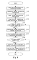
- illustrates steps of operation coordinate line-of-sight correction processing according to the first embodiment of the present disclosure;
- FIGS. 5A, B
- illustrate a concept of the operation coordinate line-of-sight correction processing;
- FIG. 6
- is a block diagram illustrating a control configuration of an image forming apparatus according to a second embodiment of the present disclosure;
- FIG. 7
- illustrates steps of operation coordinate line-of-sight correction processing according to the second embodiment of the present disclosure;
- FIG. 8
- illustrates steps of the line-of-sight correction time/area modification processing illustrated in
FIG. 7 ; - FIGS. 9A, B
- illustrate a concept of the line-of-sight correction area expansion processing illustrated in
FIG. 8 ; - FIGS. 10A, B
- illustrate a concept of the line-of-sight correction area contraction processing illustrated in
FIG. 8 ; and - FIGS. 11A, B
- illustrate a concept of the line-of-sight correction area movement processing illustrated in
FIG. 8 . - Various embodiments are described below with reference to the figures. It should be understood, however, that numerous variations from the depicted arrangements and functions are possible while remaining within the scope and spirit of the claims. For instance, one or more elements may be added, removed, combined, distributed, substituted, re-positioned, re-ordered, and/or otherwise changed. Further, where this description refers to one or more functions being implemented on and/or by one or more devices, one or more machines, and/or one or more networks, it should be understood that one or more of such entities could carry out one or more of such functions by themselves or in cooperation, and may do so by application of any suitable combination of hardware, firmware, and/or software. For instance, one or more processors may execute one or more sets of programming instructions as at least part of carrying out one or more of the functions described herein.
- First, a description will be given of an overall configuration of an electronic device according to the present disclosure with reference to
FIG. 1 andFIG. 2 . - An
image forming apparatus 1 is an example of an electronic device according to an embodiment of the present disclosure. In theimage forming apparatus 1, animage processing section 11, adocument reading section 12, adocument feeding section 13, aconveying section 14, a network transmission andreception section 15, anoperation panel section 16, animage forming section 17, atimer section 18, astorage section 19, and a line-of-sight detection section 20 are connected to acontrol section 10. Operation of each section is controlled by thecontrol section 10. - The
control section 10 is an information processing device, such as a GPP (General Purpose Processor), a CPU (Central Processing Unit), an MPU (Micro Processing Unit), a DSP (Digital Signal Processor), a GPU (Graphics Processing Unit), an ASIC (Application Specific Integrated Circuit), or the like. - The
control section 10 is configured to read a control program stored in a ROM (Read Only Memory) or a HDD (Hard Disk Drive) in thestorage section 19, and to expand and to execute the control program in a RAM (Random Access Memory) so as to operate each section of the functional blocks described later. Also, thecontrol section 10 is configured to control the overall apparatus based on instruction information input from an external terminal, or theoperation panel section 16. - The
image processing section 11 is a control operation device, such as a DSP (Digital Signal Processor), a GPU (Graphics Processing Unit), or the like. Theimage processing section 11 is a device that is configured to perform image processing on image data, and to perform various kinds of image processing, for example, expansion/contraction, density adjustment, gray scale adjustment, image improvement, and the like. - The
image processing section 11 is configured to store an image read by thedocument reading section 12 into thestorage section 19 as print data. At this time, theimage processing section 11 is capable of converting print data into a format, such as PDF, TIFF, or the like for each file. - The
document reading section 12 is a scanner that is configured to read a set document. - The
document feeding section 13 is a device that is configured to convey a document that is read by thedocument reading section 12. - The conveying
section 14 is configured to convey recording paper from a paper feeding cassette, then image forming is performed on the paper by theimage forming section 17, and after that, the paper is conveyed to a stack tray. - The network transmission and
reception section 15 is a network connecting device including a LAN board, a radio transmitter/receiver, and the like for connecting to an external network, such as a LAN, a wireless LAN, a WAN, a mobile phone network, or the like. - The network transmission and
reception section 15 is configured to transmit and to receive data through a data communication line, and to transmit and to receive an audio signal through a voice telephone line. - The
operation panel section 16 includes atouch panel 60, abutton section 61, and adisplay section 62. - The
touch panel 60 is a touch input device of an electrostatic capacitance method, a resistive film method, ultrasonic detecting method, or the like for obtaining an instruction, such as coordinates, and the like, at which a user performed operation by pressing a finger (hereinafter referred to as "touch input"). Also, thetouch panel 60 may be configured integrally with thedisplay section 62. - The
touch panel 60 obtains user's various instructions through GUI (Graphical User Interface), or the like. Specifically, thetouch panel 60 is configured to detect the coordinates of touch input by the user as an operation point. Thetouch panel 60 may detect that the operation point falls on coordinates corresponding to the coordinates on thedisplay section 62 at this time. - In this regard, if the
touch panel 60 is multi-touch enabled, a plurality of coordinates may be detected. Also, thetouch panel 60 may detect coordinates that are input by a pen point, such as a dedicated pen, or the like. Also, thetouch panel 60 may detect pressing force applied by the user. Also, if thetouch panel 60 is of electrostatic capacitance method, an ultrasonic method, or the like, thetouch panel 60 may detect coordinates on thedisplay section 62 as an operation point even if untouched by the user's finger. In this case, thetouch panel 60 may detect a distance from thedisplay section 62. - The
button section 61 is an input device including a mechanical switch, an electrostatic capacitance switch, or the like. Thebutton section 61 includes a start key, a numeric keypad, a button for changing an operation mode of a copy, a scanner, facsimile transmission/reception, and the like, and a button obtaining an instruction related to print/transmission/reception, and the like, of a selected document. - The
display section 62 is a flat display panel, such as an LCD (Liquid Crystal Display), an OELD (Organic Electro-Luminescence Display), an FED (Field Emission Display), or the like, or is a display device, such as a projector, a status display LED, or the like. Thedisplay section 62 displays at least one item, in particular, at least one and preferably various operation screens. - The
display section 62 is preferably also capable of displaying various images of GUI. Also, thedisplay section 62 is preferably capable of displaying a software keyboard for a user to input characters, and the like on thetouch panel 60. Thedisplay section 62 is preferably also capable of display corresponding to the coordinates of an operation point that was changed or not changed by the operation coordinate line-of-sight correction section described later at this time. In this regard, thedisplay section 62 is capable of displaying a preview image, or the like that is stored in thestorage section 19. - The
timer section 18 is a time acquisition device, such as a CPU internal clock, a real-time clock, a GPS (Global Positioning System) receiver, an NTP client, or the like. Thetimer section 18 is capable of obtaining real-time clock information having less error. - Also, the
timer section 18 is capable of setting a timer that generates an interrupt, or the like after the elapse of a set time period. - The
image forming section 17 forms an image on recording paper from data that is stored in thestorage section 19, read by thedocument reading section 12, or obtained from an external terminal by an output instruction of a user. - The
storage section 19 is a semiconductor memory, such as a ROM, a RAM or the like, or a storage device using a recording medium, such as an HDD, or the like. - The ROM or the HDD in the
storage section 19 stores a control program for performing operation control on theimage forming apparatus 1. In addition to this, thestorage section 19 stores the setting of user accounts. Also, thestorage section 19 may include an area, such as a document box for each user, and the like. - The line-of-
sight detection section 20 is a line-of-sight detection device including a plurality of cameras, a DSP, and the like, for example.FIG. 2 illustrates an example of an outer view of theoperation panel section 16, and the line-of-sight detection section 20 of theimage forming apparatus 1. - The line-of-
sight detection section 20 detects, for example a user's face and eyes from the captured image data, and further calculates a line of sight in a three-dimensional vector format, or the like. The line-of-sight detection section 20 calculates the coordinates (hereinafter referred to as "gaze point coordinates") of an intersection point between the user's line of sight and thetouch panel 60, and sets the coordinates in the gaze point. At this time, the line-of-sight detection section 20 calculates the average values of gaze point coordinates, or the coordinates having the longest gaze time as the coordinates of agaze point 220 in atime range 210 before and after a time point of touch input by the user on thetouch panel 60. Also, the line-of-sight detection section 20 may calculate the value of a gaze probability, or the like that is a calculation probability of a gaze point from a gaze time of each gaze point coordinates, a movement vector of the gaze point coordinates, the variance of gaze point coordinates, and the like. - In this regard, the time range is set to a shorter value than a time period during touch input before and after the target touch input. The touch input intervals have differences among individuals. Accordingly, the average value of the intervals of touch input is measured when a user uses the
operation panel section 16, and a time range for each user may be determined based on the measured value. For example, the time range may be the average value of touch input intervals, or may be a value produced by dividing the average value by a certain value. - Also, it is possible to dispose the line-of-
sight detection section 20 in theoperation panel section 16. In the example illustrated inFIG. 2 , the line-of-sight detection section 20 is disposed at an end of theoperation panel section 16. However, the line-of-sight detection section 20 may be disposed on the face of theoperation panel section 16, or may be disposed in theoperation panel section 16. Also, the line-of-sight detection section 20 may be disposed at a position away from theoperation panel section 16. Also, the line-of-sight detection section 20 may be provided with an illumination section that illuminates the user, and the like. - In this regard, in the
image forming apparatus 1, thecontrol section 10 and theimage processing section 11 may be formed integrally like a CPU with integrated GPU, a chip-on-module package, or the like. - Also, the
control section 10 or theimage processing section 11 may include a RAM, a ROM, a flash memory, or the like. - Also, the
image forming apparatus 1 may include a FAX transmission/reception section that performs facsimile transmission and reception. - Next, a description will be given of control configuration of the
image forming apparatus 1 with reference toFIG. 3 . - The
control section 10 of theimage forming apparatus 1 includes a line-of-sight correctionarea calculation section 100, an operation coordinate line-of-sight correction section 110, and a line-of-sight correction time/area modification section 130. - The
storage section 19 stores anoperation point 200, thetime range 210, thegaze point 220, a line-of-sight correction area 230, and a line-of-sight correction range 240. - The line-of-sight correction
area calculation section 100 calculates the coordinates of the line-of-sight correction area 230 from the coordinates of thegaze point 220 on thetouch panel 60, which was calculated by the line-of-sight detection section 20, and the line-of-sight correction range 240, and stores the coordinates into thestorage section 19. The line-of-sight correctionarea calculation section 100 calculates, for example coordinates in the line-of-sight correction range 240 as the line-of-sight correction area 230 with thegaze point 220 as center coordinates. - The operation coordinate line-of-
sight correction section 110 changes the coordinates of theoperation point 200 based on the line-of-sight correction area 230 calculated by the line-of-sight correctionarea calculation section 100. If theoperation point 200 is in the line-of-sight correction area 230, the operation coordinate line-of-sight correction section 110 changes the coordinates of theoperation point 200 to the coordinates of thegaze point 220. Also, if theoperation point 200 is not within the line-of-sight correction area 230, the operation coordinate line-of-sight correction section 110 does not change the coordinates of theoperation point 200. - Also, the operation coordinates line-of-
sight correction section 110 calls each processing of GUI after correcting these coordinates. - Also, after the operation coordinate line-of-
sight correction section 110 changed the coordinates of theoperation point 200, when a user corrects the display of a character by new touch input, the operation coordinate line-of-sight correction section 110 may perform processing so as not to change the coordinates of theoperation point 200 of the new touch input corresponding to the correction of the display again. - The line-of-sight correction time/
area modification section 130 modifies thetime range 210, and the range set by the line-of-sight correction area 230. After the operation coordinate line-of-sight correction section 110 changed the coordinates of theoperation point 200, the line-of-sight correction time/area modification section 130 detects correction of a display of the GUI input character by the user. If the line-of-sight correction time/area modification section 130 detects correction of the display, the line-of-sight correction time/area modification section 130 corrects this. The line-of-sight correction time/area modification section 130 changes thetime range 210 from the set value at this time, or changes the extent or the shape of the line-of-sight correction area 230. - The
operation point 200 is the data of the coordinates of the operation point of touch input by the user, which was detected by thetouch panel 60. Theoperation point 200 may be provided with the setting of the display coordinates on the screen of thedisplay section 62. Also, theoperation point 200 may include the data on the order of pressing, or the touch order of multi-touch, the direction and acceleration of movement, and the like. - The
time range 210 is data that specifies a range of a time (period) during which the line-of-sight detection section 20 calculates the coordinates of thegaze point 220. In the case of a software keyboard, it is possible to set a range of about a few seconds to a few seconds, which is a time period between a calculation start point in time, and a calculation end point before and after a time point of the touch input on thetouch panel 60, in thetime range 210. - The
gaze point 220 is data of the coordinates of the gaze point on thetouch panel 60 to which a line of sight of a user is directed, which was calculated by the line-of-sight detection section 20. The coordinates allowed to be compared with theoperation point 200, such as display coordinates on the screen of thedisplay section 62, or the like is set in thegaze point 220. Also, thegaze point 220 may include values, such as a time period during which individual gaze point coordinates are gazed, a movement vector of the gaze point coordinates, variance values of the gaze point coordinates, gaze probability, and the like. - The line-of-
sight correction area 230 is data of the coordinates of the area in which the coordinates of theoperation point 200 are changed into by the operation coordinate line-of-sight correction section 110. The line-of-sight correction area 230 is calculated by the line-of-sight correctionarea calculation section 100 using the coordinates of thegaze point 220, and the line-of-sight correction range 240. - The line-of-
sight correction range 240 is data, such as a coordinate group of a specific range for calculating the line-of-sight correction area 230, mathematical expressions, and the like by the line-of-sight correctionarea calculation section 100. The initial values of the coordinate group, and the like of the line-of-sight correction range 240 may be, for example the values in the range having a distance including a few key areas adjacent to thegaze point 220 on the software keyboard. Also, the size and the extent of this range may be modified by the line-of-sight correction time/area modification section 130. - In this regard, the line-of-
sight correction range 240 may be data for identifying a circle with thegaze point 220 as center, an ellipse, or any shape of the range. Also, in the case where the shape of this range is an ellipse, the range may be set based on the number of keys on the software keyboard horizontally and vertically in a major axis and a minor axis. Also, as the shape of this range, a shape of an area including a plurality of keys on the software keyboard may be specified. - Here, the
control section 10 of theimage forming apparatus 1 executes the control program stored in thestorage section 19 so as to function as the line-of-sight correctionarea calculation section 100, the operation coordinate line-of-sight correction section 110, and the line-of-sight correction time/area modification section 130. - Also, each section in the above-described
image forming apparatus 1 becomes a hardware resource for executing a method of forming an image according to the present disclosure. - Next, a description will be given of operation coordinate line-of-sight correction processing by the
image forming apparatus 1 according to the embodiment of the present disclosure with reference toFIG. 4 andFIG. 5 . - In the operation coordinate line-of-sight correction processing in the first embodiment, the line-of-
sight correction range 240 having thegaze point 220 pointed by the line of sight as center is calculated as the line-of-sight correction area 230. After that, if theoperation point 200 that was touch input is inside the line-of-sight correction area 230, it is assumed that thegaze point 220 is touched, and the coordinates of theoperation point 200 are changed (hereinafter, in this manner, correcting the coordinates of theoperation point 200 by a line of sight on a specific condition is referred to as "correct a line-of-sight"). If theoperation point 200 is outside the line-of-sight correction area 230, the coordinates of theoperation point 200 is not changed, and the operation place is determined to have been touched without change. - In the operation coordinate line-of-sight correction processing in the first embodiment, the
control section 10 mainly executes the program stored in thestorage section 19 in collaboration with each section using the hardware resource. - In the following, a description will be given of the details of the operation coordinate line-of-sight correction processing for each step with reference to a flowchart in
FIG. 4 . - First, the
control section 10 performs line of sight detection start processing as the line-of-sight correctionarea calculation section 100. - When the GUI displays a screen for acquiring a user's instruction from the
touch panel 60, such as a software keyboard, or the like, thecontrol section 10 starts line-of-sight detection by the line-of-sight detection section 20. Thereby, the line-of-sight detection section 20 starts line-of-sight detection, and start calculating agaze point 220. - Next, the
touch panel 60 performs operation point detection processing. - When the
touch panel 60 detects touch input caused by pressing a finger by a user, thetouch panel 60 sets the coordinates on theoperation point 200 that was touch input, and stores the coordinates into thestorage section 19. Also, thetouch panel 60 notifies a time point of this touch input to the line-of-sight detection section 20. - Next, the line-of-
sight detection section 20 performs gaze point calculation processing. - The line-of-
sight detection section 20 calculates data of the gaze point coordinates on thetouch panel 60 where a user's line of sight is directed in thetime range 210 before and after a time point of the touch input. The line-of-sight detection section 20 calculates the coordinates of thegaze point 220 from the data of the calculated gaze point coordinates, and stores the data into thestorage section 19. The line-of-sight detection section 20 notifies that the line-of-sight detection section 20 has calculated the coordinates of thegaze point 220 to thecontrol section 10. - Next, the
control section 10 performs line-of-sight correction area calculation processing as the line-of-sight correctionarea calculation section 100. - The
control section 10 calculates a group of coordinates of the line-of-sight correction range 240 with thegaze point 220 as center, and the like as the line-of-sight correction area 230 by the notification from the line-of-sight detection section 20. - In a screen example 500 in
FIG. 5A , and in a screen example 501 inFIG. 5B , examples are displayed in which a line-of-sight correction area 230 is displayed as a circle having a diameter including one to three key images on a software keyboard with thegaze point 220 as center. InFIG. 5A and FIG. 5B , adisplay field 600 that is an input field of characters, and asoftware keyboard 610 for inputting characters into thedisplay field 600 are drawn. Also, abutton 700 is a button that indicates the completion of input. - Next, the
control section 10 determines whether theoperation point 200 is positioned inside the line-of-sight correction area 230 or not as the operation coordinate line-of-sight correction section 110. As the screen example 500 inFIG. 5A , if theoperation point 200 is positioned inside the line-of-sight correction area 230, thecontrol section 10 determines as "Yes". On the contrary, if theoperation point 200 is positioned outside the line-of-sight correction area 230 as the screen example 501 inFIG. 5B , thecontrol section 10 determines as "No". In this regard, even when theoperation point 200 is positioned inside the correction area, if a value, such as a gaze probability, or the like is equal to or less than a threshold value, thecontrol section 10 may determine as "No". - If determined as "Yes", the
control section 10 causes the processing to proceed to step S106. - If determined as "No", the
control section 10 causes the processing to proceed to step S107. - If the
operation point 200 is positioned inside the line-of-sight correction area 230, thecontrol section 10 performs operation point coordinate change processing as the operation coordinate line-of-sight correction section 110. - The
control section 10 changes the coordinates of the operation point to the coordinates of thegaze point 220. At this time, thecontrol section 10 may not simply change the coordinates of the operation point to the coordinates of thegaze point 220, but may change the coordinates to specific coordinates. The specific coordinates may be a center of a key on the software keyboard that includes thegaze point 220, or the like, for example. - Here, the
control section 10 performs operation point instruction operation execution processing as the operation coordinate line-of-sight correction section 110. - The
control section 10 notifies the GUI that processing corresponding to the user's touch input is to be executed on the coordinates of the operation point 200 (if the operation point coordinate change processing in step S106 has been performed, theoperation point 200 that was changed to thegaze point 220. Also, if the operation point coordinate change processing in step S106 has not been performed, it is theoperation point 200 that was touch input). Thereby, for example, if the GUI is a software keyboard, thecontrol section 10 input characters, and the like corresponding to the key at the notified place of theoperation point 200 through the GUI, and displays the characters in the input field of thedisplay section 62, or the like. - Next, the
control section 10 determines whether there has been a user correction or not as the line-of-sight correction time/area modification section 130. Thecontrol section 10 determines as "Yes" on the characters, or the like that was input in step S107 if there has been a correction by a user. Specifically, in the case of a software keyboard, if the user has pressed a "correction" key on the characters input by the user, or the like, and has touch input the other characters, and thus there has been a correction, thecontrol section 10 determines as "Yes". Otherwise, for example, if the user has input the other characters without correction, or has pressed thecompletion button 700, thecontrol section 10 determines as "No". - If determined as "Yes", the
control section 10 causes the processing to proceed to step S109. - If determined as "No", the
control section 10 terminates the operation coordinate line-of-sight correction processing. - In the above-described step S108, if there has been a correction by the user, the
control section 10 performs the operation point coordinate change suppression processing as the line-of-sight correction time/area modification section 130. - The above-described touch input of the other characters is performed based on a key corresponding to the coordinates of the operation point of the touch input at the time of user correction.
- At this time, the
control section 10 performs control with respect to the operation point of touch input of the other characters so as not to perform the operation point coordinate change processing by the operation coordinate line-of-sight correction section 110. That is to say, thecontrol section 10 does not change the coordinates of theoperation point 200 of touch input corresponding to the display correction again. - In this regard, depending on the setting stored in the
storage section 19, the control section may make the range of the change of the coordinates of theoperation point 200 smaller, or may not allow the change at all at the time of this processing. - Next, the
control section 10 performs line-of-sight correction time/area modification processing as the line-of-sight correction time/area modification section 130. - For example, in the case of a software keyboard, it is possible for the
control section 10 to change thetime range 210 from the set value. - Also, for example, if the coordinates of the
operation point 200 before the change falls on the coordinates of the corrected key, thecontrol section 10 makes modification to narrow the line-of-sight correction range 240 so that the coordinates of theoperation point 200 before the change are not included in the line-of-sight correction range 240. Also, on the contrary, if the coordinates of thegaze point 220 falls on the coordinates of the corrected key, thecontrol section 10 makes modification to widen the line-of-sight correction range 240 so that the coordinates of theoperation point 200 are included in the line-of-sight correction range 240. - By the above, the operation coordinate line-of-sight correction processing according to the embodiment of the present disclosure is terminated.
- An electronic device according to a second embodiment has the same overall configuration as that of the
image forming apparatus 1 according to the first embodiment illustrated inFIG. 1 andFIG. 2 . - A description will be given of the control configuration of the
image forming apparatus 1 with reference toFIG. 6 . - The
control section 10 of theimage forming apparatus 1 includes a line-of-sight correctionarea calculation section 100, an operation coordinate line-of-sight correction section 110, an operation correction resultinformation holding section 120, and a line-of-sight correction time/area modification section 130. - The
storage section 19 stores theoperation point 200, thetime range 210, thegaze point 220, the line-of-sight correction area 230, the line-of-sight correction range 240, and operation correction resultinformation 250. - The line-of-sight correction
area calculation section 100 calculates the coordinates of the line-of-sight correction area 230 from the coordinates of thegaze point 220 calculated by the line-of-sight detection section 20 on thetouch panel 60, and the line-of-sight correction range 240, and stores the coordinates into thestorage section 19. The line-of-sight correctionarea calculation section 100 calculates, for example the coordinates in the line-of-sight correction range 240 with thegaze point 220 as center coordinates as the line-of-sight correction area 230. At this time, the line-of-sight correctionarea calculation section 100 refers to the specific coordinate change values included in the line-of-sight correction range 240, and calculates the line-of-sight correction area 230. - The operation coordinate line-of-
sight correction section 110 is the same as the operation coordinate line-of-sight correction section 110 in the first embodiment. - The operation correction result
information holding section 120 stores the coordinates of theoperation point 200, the coordinates of thegaze point 220, and the change result of the coordinates of theoperation point 200 by the operation coordinate line-of-sight correction section 110 into thestorage section 19 as the operation correction resultinformation 250, and holds the information. - Also, the operation correction result
information holding section 120 may also hold the user's operation history of display correction of characters, and the like as the operation correction resultinformation 250. - The line-of-sight correction time/
area modification section 130 modifies the ranges of thetime range 210, and the line-of-sight correction area 230. The line-of-sight correction time/area modification section 130 detects the correction of a display, such as characters, and the like of the GUI input by the user after the change of the coordinate of theoperation point 200 by the operation coordinate line-of-sight correction section 110. When the line-of-sight correction time/area modification section 130 detects the display correction, the line-of-sight correction time/area modification section 130 displays the correction, that is, the corrected character, on thedisplay section 62. At this time, the line-of-sight correction time/area modification section 130 changes thetime range 210 from the set value, or changes the width or the shape of the line-of-sight correction area 230. - Also, if the user's correction matches the display of the
gaze point 220, the line-of-sight correction time/area modification section 130 expands the line-of-sight correction area 230, else if the user's correction matches the display of theoperation point 200, the line-of-sight correction time/area modification section 130 contracts the line-of-sight correction area 230, and else if the user's correction matched neither the display of thegaze point 220 nor the display of theoperation point 200, the line-of-sight correction time/area modification section 130 refers to the operation correction resultinformation 250, and moves the line-of-sight correction range 240. - The
operation point 200, thetime range 110, thegaze point 220, the line-of-sight correction area 230, and the line-of-sight correction range 240 are defined in the same manner as the first embodiment. - However, when the line-of-sight correction
area calculation section 100 calculates the line-of-sight correction area 230 from thegaze point 220 calculated by the line-of-sight detection section 20, the line-of-sight correction range 240 may include a specific coordinate change value to be used for changing the coordinates, and the like as an offset value, or the like. - The operation correction result
information 250 is data on the change result history, and the like of the coordinates of theoperation point 200, the coordinates of thegaze point 220, and the coordinates of theoperation point 200 by the operation coordinate line-of-sight correction section 110. The operation correction resultinformation 250 is held for a specific retention period or a retention quantity in order to automatically change the line-of-sight correction area 230. It is possible to set a specific time period, for example about a few seconds to a few minutes for this specific retention period. Also, for a specific retention quantity, for example, in the case of a software keyboard, it is possible to set the amount of input data of a specific number of characters, such as one character to tens of characters. In this regard, a necessary amount of operation correction resultinformation 250 may be retained correspondingly to the storage capacity of thestorage section 19. Also, the operation correction resultinformation 250 may include information related to the operation history of user's display correction, and the like. - Here, the
control section 10 of theimage forming apparatus 1 executes the operation support program included in the control program stored in thestorage section 19 so as to function as the line-of-sight correctionarea calculation section 100, the operation coordinate line-of-sight correction section 110, the operation correction resultinformation holding section 120, and the line-of-sight correction time/area modification section 130. - Also, each section in the above-described
image forming apparatus 1 becomes a hardware resource for executing a method of forming an image according to the present disclosure. - Next, a description will be given of the operation coordinate line-of-sight correction processing by the
image forming apparatus 1 according to the embodiment of the present disclosure with reference toFIG. 7 andFIG. 8 . - In the operation coordinate line-of-sight correction processing in the second embodiment, the line-of-
sight correction range 240 having thegaze point 220 pointed by the line of sight as center is calculated as the line-of-sight correction area 230. After that, if theoperation point 200 that was touch input is inside the line-of-sight correction area 230, it is assumed that thegaze point 220 is touched, and the coordinates of theoperation point 200 are changed (hereinafter, in this manner, correcting the coordinates of theoperation point 200 by a line of sight on a specific condition is referred to as "correct a line-of-sight"). If theoperation point 200 is outside the line-of-sight correction area 230, the coordinates of theoperation point 200 is not changed, and the operation place is determined to be touched without change. - In the operation coordinate line-of-sight correction processing in the second embodiment, the
control section 10 mainly executes the program stored in thestorage section 19 in collaboration with each section using the hardware resource. - In the following, a description will be given of the details of the operation coordinate line-of-sight correction processing for each step with reference to a flowchart in
FIG. 7 . - The processing in steps S1101 to S1106 is the same as the processing in steps S101 to S106 illustrated in
FIG. 4 , respectively. - Here, the
control section 10 performs operation correction result information storage processing as the operation correction resultinformation holding section 120. - For example, in the case where if what is displayed in the
display section 62 is a software keyboard, thecontrol section 10 stores the operation correction resultinformation 250 in thestorage section 19 for one character input and for each operation point coordinate change processing. The operation correction resultinformation 250 may include the coordinates of theoperation point 200, the coordinates of thegaze point 220, and the change result of the coordinates of theoperation point 200. - Next, the
control section 10 performs operation point instruction operation execution processing as the operation coordinate line-of-sight correction section 110. - The
control section 10 notifies the GUI to execute the processing corresponding to the user's touch input on the coordinates of the operation point 200 (if the operation point coordinate change processing in step S1106 has been performed, theoperation point 200 that was changed to thegaze point 220. Also, if the operation point coordinate change processing in step S1106 has not been performed, theoperation point 200 that was touch input). Thereby, for example, in the case where the GUI is a software keyboard, thecontrol section 10 inputs the characters, or the like corresponding to the key of the place of the notifiedoperation point 200 by the GUI, and displays the characters, or the like in the input field or the like of thedisplay section 62. - Next, the
control section 10 determines whether there has been a user correction as the line-of-sight correction time/area modification section 130. If there has been a correction by the user on the character, and the like that were input in step S1108, and displayed, thecontrol section 10 determines as "Yes". Specifically, in the case of a software keyboard, if the user has pressed a "correction" key on the input characters, and the like, and has touch input the other characters, that means there has been a correction, and thus thecontrol section 10 determines as "Yes". Otherwise, for example, if the user has input the other characters without correction or has pressed thecompletion button 700, thecontrol section 10 determines as "No". - If determined as "Yes", the
control section 10 causes the processing to proceed to step S1110. - If determined as "No", the
control section 10 terminates the operation coordinate line-of-sight correction processing. - If there has been a user's correction, the
control section 10 performs the operation point coordinate change suppression processing in the above-described step S1109 as the line-of-sight correction time/area modification section 130. - The above-described touch input of the other characters is performed based on the key corresponding to the coordinates of the operation point of the touch input at the time of user correction.
- At this time, the
control section 10 controls the operation coordinate line-of-sight correction section 110 not to perform operation point coordinate change processing on the operation point of the touch input of the other characters. That is to say, thecontrol section 10 does not change the coordinates of theoperation point 200 of the touch input corresponding to the display correction again. - In this regard, at the time of this processing, depending on the setting stored in the
storage section 19, thecontrol section 10 may make the range of the change in the coordinates of theoperation point 200 smaller, or may not change the range at all. - Also, the
control section 10 may also store the result of the correction into thestorage section 19 by including the result of the correction in the operation correction resultinformation 250 as the operation correction resultinformation holding section 120. - Next, the
control section 10 performs line-of-sight correction time/area modification processing as the line-of-sight correction time/area modification section 130. - A description will be given of the details of the line-of-sight correction time/area modification processing in the following.
- By the above, the operation coordinate line-of-sight correction processing according to the embodiment of the present disclosure is terminated.
- In the following, a description will be given of the details of the line-of-sight correction time/area modification processing for each step with reference to a flowchart in
FIG. 8 , andFIG. 9A toFIG. 11B . - First, the
control section 10 determines whether the user's correction matches the display of thegaze point 220 or not. - The
control section 10 refers to the operation correction resultinformation 250 on the display correction of the character, and the like, which were input in step S1108, and if the corrected display matches the display of thegaze point 220, thecontrol section 10 determines as "Yes". In the example inFIG. 9A , the character "D" of the correcteddisplay 260 matches the character pointed by thegaze point 220, and thus thecontrol section 10 determines as "Yes". In the other cases, that is to say, if the corrected display does not match the display pointed by thegaze point 220, thecontrol section 10 determines as "No". - If determined as "Yes", the
control section 10 causes the processing to proceed to step S1202. - If determined as "No", the
control section 10 causes the processing to proceed to step S1203. - If the correction matches the display of the
gaze point 220, thecontrol section 10 performs line-of-sight correction area expansion processing. - According to the example in
FIG. 9B , thecontrol section 10 expands the line-of-sight correction range 240 to perform modification so that theoperation point 200 is included in the line-of-sight correction area 230. After that, when coordinates such as theoperation point 200 is input on thetouch panel 60, for example if the user directs the line of sight to the coordinates of thegaze point 220, the coordinates are included in the line-of-sight correction area 230 calculated from the line-of-sight correction range 240, and thus it becomes possible to perform correction of the line of sight. Thereby, it is possible to reduce user's input errors. - After that, the
control section 10 terminates the line-of-sight correction time/area modification processing. - If the correction does not match the display of the
gaze point 220, thecontrol section 10 determines whether the user's correction matches the display of theoperation point 200 or not. - The
control section 10 refers to the operation correction resultinformation 250, and if the corrected display matches the display of theoperation point 200, thecontrol section 10 determines as "Yes". By the example inFIG. 10A , the character "X" of the correcteddisplay 260 matches the character pointed by theoperation point 200, and thus thecontrol section 10 determines as "Yes". Otherwise, that is to say, if the corrected display does not match the display pointed by theoperation point 200, thecontrol section 10 determines as "No". - If determined as "Yes", the
control section 10 causes the processing to proceed to step S1204. - If determined as "No", the
control section 10 causes the processing to proceed to step S1205. - If the correction matches the display of the
operation point 200, thecontrol section 10 performs line-of-sight correction area contraction processing. - By the example in
FIG. 10B , thecontrol section 10 contracts the line-of-sight correction range 240 to perform modification so that theoperation point 200 is not included in the line-of-sight correction area 230. Thereby, after that, even when coordinates, such as theoperation point 200 are input on thetouch panel 60, for example, if the user directs the line of sight to the coordinates of thegaze point 220, the coordinates is outside the line-of-sight correction area 230 calculated by the line-of-sight correction range 240, and thus the line-of-sight correction is not performed. Accordingly, it is possible to prevent miss-correction by the line of sight correction, and to improve user's usability. - After that, the
control section 10 terminates the line-of-sight correction time/area modification processing. - Here, if the correction does not match the display of the
operation point 200, that is to say, if the correction matches neither thegaze point 220 nor theoperation point 200, thecontrol section 10 performs line-of-sight correction area movement processing. In the line-of-sight correction area movement processing, thecontrol section 10 refers to the history of the operation correction resultinformation 250, and moves the coordinates of the line-of-sight correction range 240, or the like. -
FIG. 11A illustrates an example in which although the character pointed by theoperation point 200 matches the character pointed by thegaze point 220, and thus the line-of-sight correction had not been performed, a user corrected the character of thedisplay 260 to "S". In this example, thecontrol section 10 made a change so as to move the coordinate change value included in the line-of-sight correction range 240 to the left by specific coordinates. -
FIG. 11B illustrates an example in which after the line-of-sight correction range 240 is changed, the coordinates as theoperation point 200 are input on thetouch panel 60, and the line-of-sight detection section 20 has detected the coordinates of thegaze point 220. In this example, thecontrol section 10 applies a coordinate change value to thegaze point 220 to calculate the coordinates of a gaze point 220', and calculates the line-of-sight correction area 230 corresponding to the coordinates of the gaze point 220'. Thereby, the line-of-sight correction as intended by the user is performed, and the character "S" is input. - Here, the
control section 10 may refer to the history of the display correction of a plurality of characters, or the like of the operation correction resultinformation 250, and calculates the average value or the median of the differences between the corrected display and thegaze point 220, and may set this as the coordinate change value of the line-of-sight correction range 240. In this regard, thecontrol section 10 may set the average value, the median, or the like of the calculated differences directly to the coordinate change value, or may set an increase or a decrease by a specific value in the shifted direction. Also, thecontrol section 10 may not set specific coordinate change values, but may change the shape and the range of the line-of-sight correction range 240 directly. - Also, it is possible for the
control section 10 to change thetime range 210 from the set value. For example, in the case where the display is a software keyboard, thecontrol section 10 may calculate asuitable time range 210 so as to calculate the line-of-sight correction area 230 including the coordinates corresponding to the display correction of the character, and the like from history of the correction of operation correction resultinformation 250. - By the above, the line-of-sight correction time/area modification processing according to the second embodiment is terminated.
- In this regard, a description has been given that the
control section 10 makes a change immediately when thecontrol section 10 changes the line-of-sight correction range 240 by the line-of-sight correction time/area modification processing in the second embodiment. However, thecontrol section 10 may not change the range immediately, but may change when a specific threshold value is exceeded. For this specific threshold value, thecontrol section 10 may make a change when the user has performed correction for a specific number of times that is larger than a few times, for example. - Also, the
control section 10 does not have to immediately change the line-of-sight correction range 240 on the screen in operation as the timing to change the line-of-sight correction range 240. That is to say, thecontrol section 10 may change the line-of-sight correction range 240 correspondingly to various conditions, such as at the time of becoming a power saving state, at the time the power is turned off, at the date and time specified by a timer, or the like, for example. - With the
image forming apparatus 1 according to the embodiment of the present disclosure, it becomes possible to perform touch input with the prevention of operation errors without the display contents being expanded, and the number of display characters being changed, or the like. Thereby, information that is allowed to be displayed is not reduced, and it is possible to improve the user's usability. - In the
image forming apparatus 1 according to the embodiment of the present disclosure, at the time of line-of-sight correction, the display contents displayed on thedisplay section 62 are not expanded, and thus the user is not confused. Thereby, it is possible to improve operationality. - Also, in the
image forming apparatus 1 according to the embodiment of the present disclosure, when a correction by a user is detected, thetime range 210 and the line-of-sight correction range 240 are modified so that it is possible to improve precision of the user's line-of-sight correction. Thereby, it becomes possible for the user to instruct a key at the place intended by the user, or the like, and thus it is possible to improve operationality. - In particular, the operation correction result
information 250 is held, and is referenced at the time of modification of the line-of-sight correction range 240 so that it becomes possible to handle the case even if the user's input display is not immediately corrected. For example, in the case of a software keyboard, even if the display of the characters, or the like that were input a few characters ahead is corrected, it is possible to modify the line-of-sight correction range 240. - In the
image forming apparatus 1 according to the embodiment of the present disclosure, it is possible to adjust the line-of-sight correction range 240 to meet the user's correction, and thus it is possible to improve precision of the line-of-sight correction. - In the
image forming apparatus 1 according to the embodiment of the present disclosure, at the time of display correction of the input character, or the like, it is possible to prevent input display from being changed unintentionally, and thus to improve the user's operationality. - Also, in the embodiment of the present disclosure, a description has been given of an example in which line-of-sight correction is performed on touch input of a key on a software keyboard. However, it is possible to apply the operation coordinate line-of-sight correction processing in the embodiment of the present disclosure to all the processing for selecting the display of an image, or the like on the GUI on the
touch panel 60 by touch input in addition to a software keyboard. That is to say, it is possible for thecontrol section 10 to perform control so as to apply the operation coordinate line-of-sight correction processing of the embodiment of the present disclosure to the case where images, characters, or the like to be selected are positioned closely one another, for example selection of a preview image, or a thumbnail image, or selection of a file. Also, it is possible for thecontrol section 10 to control not to apply the operation coordinate line-of-sight correction processing of the embodiment of the present disclosure to a GUI having few operation errors on a screen. - Also, in the embodiment of the present disclosure, a description has been given of input on the
touch panel 60 that is integrated with the screen of thedisplay section 62. However, thedisplay section 62 and thetouch panel 60 may be configured as separated with each other. In this case, it is also possible for the line-of-sight detection section 20 to detect a user's line of sight on the separatedtouch panel 60. - However, it is possible to apply the present disclosure to various electronic devices in addition to an image forming apparatus. For example, it is possible to apply the present disclosure to an information processing apparatus provided with the
touch panel 60 and the line-of-sight detection section 20, such as a smart phone, a mobile phone, a PC (Personal Computer), and a PDA (Personal Data Assistant), and the like. Also, it is possible to apply the present disclosure to home electric appliances provided with thetouch panel 60 and the line-of-sight detection section 20, such as a television set, a microwave oven, a home robot, a home security system, and the like. Also, it is possible to apply the present disclosure to a vehicle control system, such as an electric motorcycle, an automobile, an aircraft, a ship and a vessel, and the like. In addition to these, it is possible to load the present disclosure in a form of a circuit board provided with thetouch panel 60 and the line-of-sight detection section 20 on various devices as a part of the devices. - Also, the configuration and the operation of the above-described embodiments are only examples. It goes without saying that it is possible to make various changes for implementation without departing from the spirit and scope of the present disclosure.
- It should be understood that various changes and modifications to the embodiments described herein will be apparent to those skilled in the art. Such changes and modifications can be made without departing from the spirit and scope of the present subject matter and without diminishing its intended advantages. It is therefore intended that such changes and modifications be covered by the appended claims.
Claims (14)
- An electronic device (1) comprising:- a touch panel (60) that is configured to detect coordinates of an operation point (200) of a touch input by a user;- a line-of-sight detection section (20) is configured to calculate coordinates of a gaze point (220) on the touch panel (60) at which a line of sight of the user is directed in a specific time range (210) starting at a time point of the touch input on the touch panel (60) by the user;- a line-of-sight correction area calculation section (100) that is configured to calculate a line-of-sight correction area (230) in a specific range from the coordinates of the gaze point (220), calculated by the line-of-sight detection section (20), on the touch panel (60); and- an operation coordinate line-of-sight correction section (110) that is configured to change the coordinates of the operation point (200) to the coordinates of the gaze point (220) if the coordinates of the operation point (200) are within the line-of-sight correction area (230) calculated by the line-of-sight correction area calculation section (100), and that is configured not to change the coordinates of the operation point (200) if the coordinates of the operation point (200) are not within the line-of-sight correction area (230).
- The electronic device (1) according to claim 1, further comprising:- a display section (62) that is configured to display at least one item on a display, the coordinates of said at least one item displayed by the display section (62) corresponding to the coordinates of the operation point (200) changed or unchanged by the operation coordinate line-of-sight correction section (110),
wherein when the user corrects the coordinates of said at least one item displayed by the display section (62) after the operation coordinate line-of-sight correction section (110) changed the coordinates of the operation point (200), the operation coordinate line-of-sight correction section (110) is blocked to change the coordinates of the operation point (200) of the touch input corresponding to the correction of the display. - The electronic device (1) according to claim 1 or 2, further comprising:- a line-of-sight correction time/area modification section (130) that is configured to modify the time range (210) and a range of the line-of-sight correction area (230) if the user corrects the coordinates of said at least one item displayed by the display section (62) after the operation coordinate line-of-sight correction section (110) has changed the coordinates of the operation point (200).
- The electronic device (1) according to one of the claims 1 to 3, further comprising:- an operation correction result information holding section (120) that is configured to hold the coordinates of the operation point (200), the coordinates of the gaze point (220), and a result of changing the coordinates of the operation point (200) by the operation coordinate line-of-sight correction section (110) as operation correction result information (250);- a display section (62) that is configured to display at least one item on a display, the coordinates of said at least one item displayed by the display section (62) corresponding to the coordinates of the operation point (200) changed or unchanged by the operation coordinate line-of-sight correction section (110); and- a line-of-sight correction time/area modification section (130) that is configured to refer to the operation correction result information (250) held by the operation correction result information holding section (120), and that is configured to modify the time range (210) and a line-of-sight correction range (240) if correction of the display on the display section (62) by the user is detected by the electronic device (1) after the coordinates of the operation point (200) have been changed by the operation coordinate line-of-sight correction section (110),
wherein the line-of-sight correction area calculation section (100) is configured to calculate a line-of-sight correction area (230) corresponding to the line-of-sight correction range (240) from the coordinates of the gaze point (220) on the touch panel (60), calculated by the line-of-sight detection section (20). - The electronic device (1) according to claim 4, wherein:- the line-of-sight correction time/area modification section (130) is configured to expand the line-of-sight correction range (240), if correction by the user matches the display of the gaze point (220);- the line-of-sight correction time/area modification section (130) is configured to contract the line-of-sight correction range (240), if correction by the user matches the display of the operation point (200), and- the line-of-sight correction time/area modification section (130) is configured to move the line-of-sight correction range (240) by the operation correction result information (250), if correction by the user matches neither the display of the gaze point (220) nor the display of the operation point (200).
- The electronic device (1) according to claim 4 or 5,
wherein when the user corrects the display after the coordinates of the operation point (200) have been changed, the operation coordinate line-of-sight correction section (110) is blocked to change the coordinates of the operation point (200) of the touch input corresponding to correction of the display. - A method of supporting operation, the method comprising:- detecting, via a touch panel (60), coordinates of an operation point (200) of a touch input by a user;- calculating, via a line-of-sight detection section (20), coordinates of a gaze point (220) on the touch panel (60) at which a line of sight of the user is directed in a specific time range (210) starting at a time point of the touch input on the touch panel (60) by the user;- calculating, via a line-of-sight correction area calculation section (100), a line-of-sight correction area (230) in a specific range from the coordinates of the gaze point (220), calculated by the line-of-sight detection section (20), on the touch panel (60); and- changing, via an operation coordinate line-of-sight correction section (110), the coordinates of the operation point (200) to the coordinates of the gaze point (220) if the coordinates of the operation point (200) are within the line-of-sight correction area (230) calculated by the line-of-sight correction area calculation section (100), and not changing the coordinates of the operation point (200) if the coordinates of the operation point (200) are not within the line-of-sight correction area (230).
- The method according to claim 7, further comprising:- displaying, via a display section (62), at least one item on a display, the coordinates of said at least one item displayed by the display section (62) corresponding to the coordinates of the operation point (200) changed or unchanged by the operation coordinate line-of-sight correction section (110).
wherein the coordinates of the operation point (200) of the touch input corresponding to the correction of the display are not changed when the user corrects the display after the operation coordinate line-of-sight correction section (110) has changed the coordinates of the operation point (200). - The method according to claim 8, further comprising:- modifying, via a line-of-sight correction time/area modification section, the time range (210) and a range of the line-of-sight correction area (230) if the user corrects the display after the operation coordinate line-of-sight correction section (110) changes the coordinates of the operation point (200).
- The method according to claim 9, further comprising:- holding, via an operation correction result information holding section (120), the coordinates of the operation point (200), the coordinates of the gaze point (220), and a result of changing the coordinates of the operation point (200) by the operation coordinate line-of-sight correction section (110) as operation correction result information (250);- displaying, via a display section (62), at least one item on a display, the coordinates of said at least one item displayed by the display section (62) corresponding to the coordinates of the operation point (200) changed or unchanged by the operation coordinate line-of-sight correction section (110);- referring to the operation correction result information (250) held by the operation correction result information holding section (120) and modifying the time range (210) and a line-of-sight correction range (240), via a line-of-sight correction time/area modification section (130), if correction of the display on the display section (62) by the user is detected after changing the coordinates of the operation point (200) by the operation coordinate line-of-sight correction section (110); and- calculating, via the line-of-sight correction area calculation section (100) is included, the line-of-sight correction area (230) corresponding to the line-of-sight correction range (240) from the coordinates of the gaze point (220) on the touch panel (60), calculated by the line-of-sight detection section (20).
- The method of supporting operation according to claim 10, further comprising, via the line-of-sight correction time/area modification section,- expanding the line-of-sight correction range (240) if correction by the user matches the display of the gaze point (220),- contracting the line-of-sight correction range (240) if correction by the user matches the display of the operation point (200), and- moving the line-of-sight correction range (240) by the operation correction result information (250) if correction by the user matches neither the display of the gaze point (220) nor the display of the operation point (200).
- The method of supporting operation according to claim 10 or 11, wherein, when the user corrects the display after the coordinates of the operation point (200) have been changed, the coordinates of the operation point (200) of the touch input are changed, via the operation coordinate line-of-sight correction section (110), corresponding to the correction of the display.
- A non-transitory computer-readable recording medium for storing an operation support program executable by a computer, the operation support program comprising:- a first program code that causes the computer to detect coordinates of a touch input operation point (200) on a touch panel (60) by a user;- a second program code that causes the computer to calculate coordinates of a gaze point (220) on the touch panel (60) at which a line of sight of the user is directed in a specific time range (210) starting at a time point of the touch input on the touch panel (60) by the user;- a third program code that causes the computer to calculate a line-of-sight correction area (230) in a specific range from the coordinates of the gaze point (220), calculated by the second program code, on the touch panel (60);- a fourth program code that causes the computer to change the coordinates of the operation point (200) to the coordinates of the gaze point (220) if the coordinates of the operation point (200) are within the line-of-sight correction area (230) calculated by the third program code, and not to change the coordinates of the operation point (200) if the coordinates of the operation point (200) are not within the line-of-sight correction area (230).
- The non-transitory computer-readable recording medium according to claim 13, the operation support program further comprising:- an eighth program code that causes the computer to hold the coordinates of the operation point (200), the coordinates of the gaze point (220), and a result of changing the coordinates of the operation point (200) by the fourth program code as operation correction result information (250);- a ninth program code that causes the computer to display at least one item on a display, the coordinates of said at least one displayed item corresponding to the coordinates corresponding to the coordinates of the operation point (200) changed or unchanged by the fourth program code; and- a tenth program code that causes the computer to refer to the operation correction result information (250) held by the eighth program code, and to modify the time range (210) and a line-of-sight correction range (240), if correction of the display by the ninth program code is detected after changing the coordinates of the operation point (200) by the fourth program code,
wherein the third program code causes the computer to calculate the line-of-sight correction area (230) corresponding to the line-of-sight correction range (240) from the coordinates of the gaze point (220) on the touch panel (60), calculated by the second program code.
Applications Claiming Priority (2)
| Application Number | Priority Date | Filing Date | Title |
|---|---|---|---|
| JP2014010050A JP5968926B2 (en) | 2014-01-23 | 2014-01-23 | Information processing apparatus and information processing program |
| JP2014053325A JP5976708B2 (en) | 2014-03-17 | 2014-03-17 | Electronic equipment and operation support program |
Publications (2)
| Publication Number | Publication Date |
|---|---|
| EP2899611A1 true EP2899611A1 (en) | 2015-07-29 |
| EP2899611B1 EP2899611B1 (en) | 2018-12-26 |
Family
ID=52434572
Family Applications (1)
| Application Number | Title | Priority Date | Filing Date |
|---|---|---|---|
| EP15152301.6A Not-in-force EP2899611B1 (en) | 2014-01-23 | 2015-01-23 | Electronic device, method, and program for supporting touch panel operation |
Country Status (3)
| Country | Link |
|---|---|
| US (1) | US9471178B2 (en) |
| EP (1) | EP2899611B1 (en) |
| CN (1) | CN104808836B (en) |
Cited By (1)
| Publication number | Priority date | Publication date | Assignee | Title |
|---|---|---|---|---|
| WO2021237305A1 (en) * | 2020-05-29 | 2021-12-02 | Marthinus Van Der Merwe | A contactless touchscreen interface |
Families Citing this family (8)
| Publication number | Priority date | Publication date | Assignee | Title |
|---|---|---|---|---|
| JP2016143400A (en) * | 2015-02-05 | 2016-08-08 | キヤノン株式会社 | Coordinate input device and control method thereof |
| JP6583113B2 (en) | 2016-04-15 | 2019-10-02 | 株式会社デンソー | Information processing apparatus and display system |
| US10275023B2 (en) * | 2016-05-05 | 2019-04-30 | Google Llc | Combining gaze input and touch surface input for user interfaces in augmented and/or virtual reality |
| GB2551520B (en) * | 2016-06-20 | 2018-11-21 | Ge Aviat Systems Ltd | Correction of vibration-induced error for touch screen display in an aircraft |
| CN109960412B (en) * | 2019-03-22 | 2022-06-07 | 北京七鑫易维信息技术有限公司 | Method for adjusting gazing area based on touch control and terminal equipment |
| CN112987910B (en) * | 2019-12-17 | 2023-04-07 | 七鑫易维(深圳)科技有限公司 | Testing method, device, equipment and storage medium of eyeball tracking equipment |
| CN113885735B (en) * | 2021-11-03 | 2023-03-21 | 业成科技(成都)有限公司 | Touch display device, control method thereof and electronic device |
| US12299193B2 (en) * | 2022-05-27 | 2025-05-13 | Beijing Shiyan Technology Co., Ltd. | Gaze demarcating system, method, device and non-transitory computer readable storage medium |
Citations (3)
| Publication number | Priority date | Publication date | Assignee | Title |
|---|---|---|---|---|
| US5189732A (en) * | 1987-11-18 | 1993-02-23 | Hitachi, Ltd. | Touch panel input apparatus |
| JP2009110275A (en) * | 2007-10-30 | 2009-05-21 | Sharp Corp | Display input device and parallax correction method thereof |
| US20110285657A1 (en) * | 2009-03-31 | 2011-11-24 | Mitsuo Shimotani | Display input device |
Family Cites Families (8)
| Publication number | Priority date | Publication date | Assignee | Title |
|---|---|---|---|---|
| US8462949B2 (en) * | 2007-11-29 | 2013-06-11 | Oculis Labs, Inc. | Method and apparatus for secure display of visual content |
| CN102257457A (en) * | 2008-12-25 | 2011-11-23 | 富士通株式会社 | Computer program, input device, and input method |
| JP5332623B2 (en) | 2009-01-07 | 2013-11-06 | 沖電気工業株式会社 | Image display device and image display method |
| JP5387557B2 (en) * | 2010-12-27 | 2014-01-15 | カシオ計算機株式会社 | Information processing apparatus and method, and program |
| US8766936B2 (en) * | 2011-03-25 | 2014-07-01 | Honeywell International Inc. | Touch screen and method for providing stable touches |
| JP2013222438A (en) | 2012-04-19 | 2013-10-28 | Nec Casio Mobile Communications Ltd | Processing apparatus, and detection position correction method and program |
| JP5942586B2 (en) * | 2012-05-18 | 2016-06-29 | 富士通株式会社 | Tablet terminal and operation reception program |
| US9007321B2 (en) * | 2013-03-25 | 2015-04-14 | Sony Corporation | Method and apparatus for enlarging a display area |
-
2014
- 2014-12-30 CN CN201410841631.6A patent/CN104808836B/en not_active Expired - Fee Related
-
2015
- 2015-01-20 US US14/600,151 patent/US9471178B2/en not_active Expired - Fee Related
- 2015-01-23 EP EP15152301.6A patent/EP2899611B1/en not_active Not-in-force
Patent Citations (3)
| Publication number | Priority date | Publication date | Assignee | Title |
|---|---|---|---|---|
| US5189732A (en) * | 1987-11-18 | 1993-02-23 | Hitachi, Ltd. | Touch panel input apparatus |
| JP2009110275A (en) * | 2007-10-30 | 2009-05-21 | Sharp Corp | Display input device and parallax correction method thereof |
| US20110285657A1 (en) * | 2009-03-31 | 2011-11-24 | Mitsuo Shimotani | Display input device |
Cited By (2)
| Publication number | Priority date | Publication date | Assignee | Title |
|---|---|---|---|---|
| WO2021237305A1 (en) * | 2020-05-29 | 2021-12-02 | Marthinus Van Der Merwe | A contactless touchscreen interface |
| AU2021279100B2 (en) * | 2020-05-29 | 2022-09-08 | Marthinus Van Der Merwe | A contactless touchscreen interface |
Also Published As
| Publication number | Publication date |
|---|---|
| EP2899611B1 (en) | 2018-12-26 |
| CN104808836A (en) | 2015-07-29 |
| US20150205437A1 (en) | 2015-07-23 |
| US9471178B2 (en) | 2016-10-18 |
| CN104808836B (en) | 2017-12-01 |
Similar Documents
| Publication | Publication Date | Title |
|---|---|---|
| EP2899611B1 (en) | Electronic device, method, and program for supporting touch panel operation | |
| US20150378707A1 (en) | Mobile terminal and method for controlling the same | |
| EP2420914A2 (en) | Information processing apparatus, information processing method and program | |
| US20140145991A1 (en) | Information processing apparatus installed with touch panel as user interface | |
| US9696889B2 (en) | Electronic device that displays an operation screen including an object | |
| US20140043535A1 (en) | Display apparatus, information processing system and recording medium | |
| US9094549B2 (en) | Scanning technology for using a scan button to stop scanning and open edition user interface | |
| EP2343632A1 (en) | Touch panel device operating as if in the equivalent mode even when detected region is smaller than display region of display device | |
| EP2953335A1 (en) | Method of providing screen for manipulating execution of application of image forming apparatus and image forming apparatus using the method | |
| EP2950197A1 (en) | Electronic device and method of content display | |
| JP6677220B2 (en) | Mobile terminals and electronic systems | |
| US10152167B2 (en) | Operation display system, operation display device, and operation display program | |
| US20140362004A1 (en) | Input processing apparatus, information processing apparatus, information processing system, input processing method, information processing method, input processing program and information processing program | |
| JP6121564B2 (en) | Information processing apparatus, image forming apparatus, and information processing method | |
| US10154162B1 (en) | Mobile terminal and electronic system having an electronic apparatus wherein the mobile terminal includes an operation screen comprising operation buttons associated with functions performable by the electronic apparatus | |
| US11523011B2 (en) | Image forming apparatus and numerical value counting method | |
| CN114546155A (en) | Method, sensor controller and electronic device | |
| US10916032B2 (en) | Image processing apparatus, image processing program, image processing method, and image forming apparatus including the image processing apparatus | |
| US10484548B2 (en) | Operation display system, operation display apparatus, and operation display program | |
| JP5976708B2 (en) | Electronic equipment and operation support program | |
| US9456093B2 (en) | Image processing apparatus on which output candidate images less than or equal to a predetermined number are selectably displayed | |
| JP5968926B2 (en) | Information processing apparatus and information processing program | |
| CN108833731A (en) | Electronic system, electronic device, and portable terminal | |
| US20160381236A1 (en) | Information processing apparatus and storage medium | |
| US9280303B2 (en) | Mobile terminal and method for selecting documents and generating print requests |
Legal Events
| Date | Code | Title | Description |
|---|---|---|---|
| PUAI | Public reference made under article 153(3) epc to a published international application that has entered the european phase |
Free format text: ORIGINAL CODE: 0009012 |
|
| 17P | Request for examination filed |
Effective date: 20150123 |
|
| AK | Designated contracting states |
Kind code of ref document: A1 Designated state(s): AL AT BE BG CH CY CZ DE DK EE ES FI FR GB GR HR HU IE IS IT LI LT LU LV MC MK MT NL NO PL PT RO RS SE SI SK SM TR |
|
| AX | Request for extension of the european patent |
Extension state: BA ME |
|
| 17P | Request for examination filed |
Effective date: 20151120 |
|
| RBV | Designated contracting states (corrected) |
Designated state(s): AL AT BE BG CH CY CZ DE DK EE ES FI FR GB GR HR HU IE IS IT LI LT LU LV MC MK MT NL NO PL PT RO RS SE SI SK SM TR |
|
| STAA | Information on the status of an ep patent application or granted ep patent |
Free format text: STATUS: EXAMINATION IS IN PROGRESS |
|
| 17Q | First examination report despatched |
Effective date: 20171115 |
|
| GRAP | Despatch of communication of intention to grant a patent |
Free format text: ORIGINAL CODE: EPIDOSNIGR1 |
|
| STAA | Information on the status of an ep patent application or granted ep patent |
Free format text: STATUS: GRANT OF PATENT IS INTENDED |
|
| INTG | Intention to grant announced |
Effective date: 20180627 |
|
| GRAS | Grant fee paid |
Free format text: ORIGINAL CODE: EPIDOSNIGR3 |
|
| GRAA | (expected) grant |
Free format text: ORIGINAL CODE: 0009210 |
|
| STAA | Information on the status of an ep patent application or granted ep patent |
Free format text: STATUS: THE PATENT HAS BEEN GRANTED |
|
| AK | Designated contracting states |
Kind code of ref document: B1 Designated state(s): AL AT BE BG CH CY CZ DE DK EE ES FI FR GB GR HR HU IE IS IT LI LT LU LV MC MK MT NL NO PL PT RO RS SE SI SK SM TR |
|
| REG | Reference to a national code |
Ref country code: GB Ref legal event code: FG4D |
|
| REG | Reference to a national code |
Ref country code: CH Ref legal event code: EP |
|
| REG | Reference to a national code |
Ref country code: AT Ref legal event code: REF Ref document number: 1082297 Country of ref document: AT Kind code of ref document: T Effective date: 20190115 |
|
| REG | Reference to a national code |
Ref country code: DE Ref legal event code: R096 Ref document number: 602015022093 Country of ref document: DE |
|
| REG | Reference to a national code |
Ref country code: IE Ref legal event code: FG4D |
|
| PG25 | Lapsed in a contracting state [announced via postgrant information from national office to epo] |
Ref country code: FI Free format text: LAPSE BECAUSE OF FAILURE TO SUBMIT A TRANSLATION OF THE DESCRIPTION OR TO PAY THE FEE WITHIN THE PRESCRIBED TIME-LIMIT Effective date: 20181226 Ref country code: LV Free format text: LAPSE BECAUSE OF FAILURE TO SUBMIT A TRANSLATION OF THE DESCRIPTION OR TO PAY THE FEE WITHIN THE PRESCRIBED TIME-LIMIT Effective date: 20181226 Ref country code: BG Free format text: LAPSE BECAUSE OF FAILURE TO SUBMIT A TRANSLATION OF THE DESCRIPTION OR TO PAY THE FEE WITHIN THE PRESCRIBED TIME-LIMIT Effective date: 20190326 Ref country code: HR Free format text: LAPSE BECAUSE OF FAILURE TO SUBMIT A TRANSLATION OF THE DESCRIPTION OR TO PAY THE FEE WITHIN THE PRESCRIBED TIME-LIMIT Effective date: 20181226 Ref country code: NO Free format text: LAPSE BECAUSE OF FAILURE TO SUBMIT A TRANSLATION OF THE DESCRIPTION OR TO PAY THE FEE WITHIN THE PRESCRIBED TIME-LIMIT Effective date: 20190326 Ref country code: LT Free format text: LAPSE BECAUSE OF FAILURE TO SUBMIT A TRANSLATION OF THE DESCRIPTION OR TO PAY THE FEE WITHIN THE PRESCRIBED TIME-LIMIT Effective date: 20181226 |
|
| REG | Reference to a national code |
Ref country code: NL Ref legal event code: MP Effective date: 20181226 |
|
| REG | Reference to a national code |
Ref country code: LT Ref legal event code: MG4D |
|
| PG25 | Lapsed in a contracting state [announced via postgrant information from national office to epo] |
Ref country code: GR Free format text: LAPSE BECAUSE OF FAILURE TO SUBMIT A TRANSLATION OF THE DESCRIPTION OR TO PAY THE FEE WITHIN THE PRESCRIBED TIME-LIMIT Effective date: 20190327 Ref country code: RS Free format text: LAPSE BECAUSE OF FAILURE TO SUBMIT A TRANSLATION OF THE DESCRIPTION OR TO PAY THE FEE WITHIN THE PRESCRIBED TIME-LIMIT Effective date: 20181226 Ref country code: SE Free format text: LAPSE BECAUSE OF FAILURE TO SUBMIT A TRANSLATION OF THE DESCRIPTION OR TO PAY THE FEE WITHIN THE PRESCRIBED TIME-LIMIT Effective date: 20181226 Ref country code: AL Free format text: LAPSE BECAUSE OF FAILURE TO SUBMIT A TRANSLATION OF THE DESCRIPTION OR TO PAY THE FEE WITHIN THE PRESCRIBED TIME-LIMIT Effective date: 20181226 |
|
| REG | Reference to a national code |
Ref country code: AT Ref legal event code: MK05 Ref document number: 1082297 Country of ref document: AT Kind code of ref document: T Effective date: 20181226 |
|
| PG25 | Lapsed in a contracting state [announced via postgrant information from national office to epo] |
Ref country code: NL Free format text: LAPSE BECAUSE OF FAILURE TO SUBMIT A TRANSLATION OF THE DESCRIPTION OR TO PAY THE FEE WITHIN THE PRESCRIBED TIME-LIMIT Effective date: 20181226 |
|
| PG25 | Lapsed in a contracting state [announced via postgrant information from national office to epo] |
Ref country code: IT Free format text: LAPSE BECAUSE OF FAILURE TO SUBMIT A TRANSLATION OF THE DESCRIPTION OR TO PAY THE FEE WITHIN THE PRESCRIBED TIME-LIMIT Effective date: 20181226 Ref country code: ES Free format text: LAPSE BECAUSE OF FAILURE TO SUBMIT A TRANSLATION OF THE DESCRIPTION OR TO PAY THE FEE WITHIN THE PRESCRIBED TIME-LIMIT Effective date: 20181226 Ref country code: PT Free format text: LAPSE BECAUSE OF FAILURE TO SUBMIT A TRANSLATION OF THE DESCRIPTION OR TO PAY THE FEE WITHIN THE PRESCRIBED TIME-LIMIT Effective date: 20190426 Ref country code: CZ Free format text: LAPSE BECAUSE OF FAILURE TO SUBMIT A TRANSLATION OF THE DESCRIPTION OR TO PAY THE FEE WITHIN THE PRESCRIBED TIME-LIMIT Effective date: 20181226 Ref country code: PL Free format text: LAPSE BECAUSE OF FAILURE TO SUBMIT A TRANSLATION OF THE DESCRIPTION OR TO PAY THE FEE WITHIN THE PRESCRIBED TIME-LIMIT Effective date: 20181226 |
|
| PG25 | Lapsed in a contracting state [announced via postgrant information from national office to epo] |
Ref country code: EE Free format text: LAPSE BECAUSE OF FAILURE TO SUBMIT A TRANSLATION OF THE DESCRIPTION OR TO PAY THE FEE WITHIN THE PRESCRIBED TIME-LIMIT Effective date: 20181226 Ref country code: SM Free format text: LAPSE BECAUSE OF FAILURE TO SUBMIT A TRANSLATION OF THE DESCRIPTION OR TO PAY THE FEE WITHIN THE PRESCRIBED TIME-LIMIT Effective date: 20181226 Ref country code: SK Free format text: LAPSE BECAUSE OF FAILURE TO SUBMIT A TRANSLATION OF THE DESCRIPTION OR TO PAY THE FEE WITHIN THE PRESCRIBED TIME-LIMIT Effective date: 20181226 Ref country code: RO Free format text: LAPSE BECAUSE OF FAILURE TO SUBMIT A TRANSLATION OF THE DESCRIPTION OR TO PAY THE FEE WITHIN THE PRESCRIBED TIME-LIMIT Effective date: 20181226 Ref country code: IS Free format text: LAPSE BECAUSE OF FAILURE TO SUBMIT A TRANSLATION OF THE DESCRIPTION OR TO PAY THE FEE WITHIN THE PRESCRIBED TIME-LIMIT Effective date: 20190426 |
|
| REG | Reference to a national code |
Ref country code: CH Ref legal event code: PL |
|
| REG | Reference to a national code |
Ref country code: DE Ref legal event code: R097 Ref document number: 602015022093 Country of ref document: DE |
|
| PG25 | Lapsed in a contracting state [announced via postgrant information from national office to epo] |
Ref country code: LU Free format text: LAPSE BECAUSE OF NON-PAYMENT OF DUE FEES Effective date: 20190123 |
|
| REG | Reference to a national code |
Ref country code: BE Ref legal event code: MM Effective date: 20190131 |
|
| REG | Reference to a national code |
Ref country code: IE Ref legal event code: MM4A |
|
| PG25 | Lapsed in a contracting state [announced via postgrant information from national office to epo] |
Ref country code: MC Free format text: LAPSE BECAUSE OF FAILURE TO SUBMIT A TRANSLATION OF THE DESCRIPTION OR TO PAY THE FEE WITHIN THE PRESCRIBED TIME-LIMIT Effective date: 20181226 Ref country code: DK Free format text: LAPSE BECAUSE OF FAILURE TO SUBMIT A TRANSLATION OF THE DESCRIPTION OR TO PAY THE FEE WITHIN THE PRESCRIBED TIME-LIMIT Effective date: 20181226 Ref country code: AT Free format text: LAPSE BECAUSE OF FAILURE TO SUBMIT A TRANSLATION OF THE DESCRIPTION OR TO PAY THE FEE WITHIN THE PRESCRIBED TIME-LIMIT Effective date: 20181226 |
|
| PLBE | No opposition filed within time limit |
Free format text: ORIGINAL CODE: 0009261 |
|
| STAA | Information on the status of an ep patent application or granted ep patent |
Free format text: STATUS: NO OPPOSITION FILED WITHIN TIME LIMIT |
|
| PG25 | Lapsed in a contracting state [announced via postgrant information from national office to epo] |
Ref country code: BE Free format text: LAPSE BECAUSE OF NON-PAYMENT OF DUE FEES Effective date: 20190131 |
|
| 26N | No opposition filed |
Effective date: 20190927 |
|
| PG25 | Lapsed in a contracting state [announced via postgrant information from national office to epo] |
Ref country code: LI Free format text: LAPSE BECAUSE OF NON-PAYMENT OF DUE FEES Effective date: 20190131 Ref country code: CH Free format text: LAPSE BECAUSE OF NON-PAYMENT OF DUE FEES Effective date: 20190131 |
|
| PG25 | Lapsed in a contracting state [announced via postgrant information from national office to epo] |
Ref country code: IE Free format text: LAPSE BECAUSE OF NON-PAYMENT OF DUE FEES Effective date: 20190123 |
|
| PG25 | Lapsed in a contracting state [announced via postgrant information from national office to epo] |
Ref country code: SI Free format text: LAPSE BECAUSE OF FAILURE TO SUBMIT A TRANSLATION OF THE DESCRIPTION OR TO PAY THE FEE WITHIN THE PRESCRIBED TIME-LIMIT Effective date: 20181226 |
|
| PG25 | Lapsed in a contracting state [announced via postgrant information from national office to epo] |
Ref country code: TR Free format text: LAPSE BECAUSE OF FAILURE TO SUBMIT A TRANSLATION OF THE DESCRIPTION OR TO PAY THE FEE WITHIN THE PRESCRIBED TIME-LIMIT Effective date: 20181226 |
|
| PG25 | Lapsed in a contracting state [announced via postgrant information from national office to epo] |
Ref country code: MT Free format text: LAPSE BECAUSE OF NON-PAYMENT OF DUE FEES Effective date: 20190123 |
|
| PG25 | Lapsed in a contracting state [announced via postgrant information from national office to epo] |
Ref country code: CY Free format text: LAPSE BECAUSE OF FAILURE TO SUBMIT A TRANSLATION OF THE DESCRIPTION OR TO PAY THE FEE WITHIN THE PRESCRIBED TIME-LIMIT Effective date: 20181226 |
|
| PG25 | Lapsed in a contracting state [announced via postgrant information from national office to epo] |
Ref country code: HU Free format text: LAPSE BECAUSE OF FAILURE TO SUBMIT A TRANSLATION OF THE DESCRIPTION OR TO PAY THE FEE WITHIN THE PRESCRIBED TIME-LIMIT; INVALID AB INITIO Effective date: 20150123 |
|
| PGFP | Annual fee paid to national office [announced via postgrant information from national office to epo] |
Ref country code: GB Payment date: 20211206 Year of fee payment: 8 Ref country code: FR Payment date: 20211216 Year of fee payment: 8 |
|
| PGFP | Annual fee paid to national office [announced via postgrant information from national office to epo] |
Ref country code: DE Payment date: 20211130 Year of fee payment: 8 |
|
| PG25 | Lapsed in a contracting state [announced via postgrant information from national office to epo] |
Ref country code: MK Free format text: LAPSE BECAUSE OF FAILURE TO SUBMIT A TRANSLATION OF THE DESCRIPTION OR TO PAY THE FEE WITHIN THE PRESCRIBED TIME-LIMIT Effective date: 20181226 |
|
| REG | Reference to a national code |
Ref country code: DE Ref legal event code: R119 Ref document number: 602015022093 Country of ref document: DE |
|
| GBPC | Gb: european patent ceased through non-payment of renewal fee |
Effective date: 20230123 |
|
| PG25 | Lapsed in a contracting state [announced via postgrant information from national office to epo] |
Ref country code: GB Free format text: LAPSE BECAUSE OF NON-PAYMENT OF DUE FEES Effective date: 20230123 Ref country code: DE Free format text: LAPSE BECAUSE OF NON-PAYMENT OF DUE FEES Effective date: 20230801 |
|
| PG25 | Lapsed in a contracting state [announced via postgrant information from national office to epo] |
Ref country code: FR Free format text: LAPSE BECAUSE OF NON-PAYMENT OF DUE FEES Effective date: 20230131 |