EP2899610A1 - Visual feedback method and apparatus for touch selection - Google Patents
Visual feedback method and apparatus for touch selection Download PDFInfo
- Publication number
- EP2899610A1 EP2899610A1 EP14812114.8A EP14812114A EP2899610A1 EP 2899610 A1 EP2899610 A1 EP 2899610A1 EP 14812114 A EP14812114 A EP 14812114A EP 2899610 A1 EP2899610 A1 EP 2899610A1
- Authority
- EP
- European Patent Office
- Prior art keywords
- touch
- area
- pressure
- feedback graph
- feedback
- Prior art date
- Legal status (The legal status is an assumption and is not a legal conclusion. Google has not performed a legal analysis and makes no representation as to the accuracy of the status listed.)
- Granted
Links
Images


Classifications
-
- G—PHYSICS
- G06—COMPUTING OR CALCULATING; COUNTING
- G06F—ELECTRIC DIGITAL DATA PROCESSING
- G06F3/00—Input arrangements for transferring data to be processed into a form capable of being handled by the computer; Output arrangements for transferring data from processing unit to output unit, e.g. interface arrangements
- G06F3/01—Input arrangements or combined input and output arrangements for interaction between user and computer
- G06F3/048—Interaction techniques based on graphical user interfaces [GUI]
- G06F3/0487—Interaction techniques based on graphical user interfaces [GUI] using specific features provided by the input device, e.g. functions controlled by the rotation of a mouse with dual sensing arrangements, or of the nature of the input device, e.g. tap gestures based on pressure sensed by a digitiser
- G06F3/0488—Interaction techniques based on graphical user interfaces [GUI] using specific features provided by the input device, e.g. functions controlled by the rotation of a mouse with dual sensing arrangements, or of the nature of the input device, e.g. tap gestures based on pressure sensed by a digitiser using a touch-screen or digitiser, e.g. input of commands through traced gestures
-
- G—PHYSICS
- G06—COMPUTING OR CALCULATING; COUNTING
- G06F—ELECTRIC DIGITAL DATA PROCESSING
- G06F3/00—Input arrangements for transferring data to be processed into a form capable of being handled by the computer; Output arrangements for transferring data from processing unit to output unit, e.g. interface arrangements
- G06F3/01—Input arrangements or combined input and output arrangements for interaction between user and computer
- G06F3/03—Arrangements for converting the position or the displacement of a member into a coded form
- G06F3/041—Digitisers, e.g. for touch screens or touch pads, characterised by the transducing means
- G06F3/0412—Digitisers structurally integrated in a display
-
- G—PHYSICS
- G06—COMPUTING OR CALCULATING; COUNTING
- G06F—ELECTRIC DIGITAL DATA PROCESSING
- G06F3/00—Input arrangements for transferring data to be processed into a form capable of being handled by the computer; Output arrangements for transferring data from processing unit to output unit, e.g. interface arrangements
- G06F3/01—Input arrangements or combined input and output arrangements for interaction between user and computer
- G06F3/03—Arrangements for converting the position or the displacement of a member into a coded form
- G06F3/041—Digitisers, e.g. for touch screens or touch pads, characterised by the transducing means
- G06F3/0414—Digitisers, e.g. for touch screens or touch pads, characterised by the transducing means using force sensing means to determine a position
-
- G—PHYSICS
- G06—COMPUTING OR CALCULATING; COUNTING
- G06F—ELECTRIC DIGITAL DATA PROCESSING
- G06F3/00—Input arrangements for transferring data to be processed into a form capable of being handled by the computer; Output arrangements for transferring data from processing unit to output unit, e.g. interface arrangements
- G06F3/01—Input arrangements or combined input and output arrangements for interaction between user and computer
- G06F3/03—Arrangements for converting the position or the displacement of a member into a coded form
- G06F3/041—Digitisers, e.g. for touch screens or touch pads, characterised by the transducing means
- G06F3/0416—Control or interface arrangements specially adapted for digitisers
-
- G—PHYSICS
- G06—COMPUTING OR CALCULATING; COUNTING
- G06F—ELECTRIC DIGITAL DATA PROCESSING
- G06F3/00—Input arrangements for transferring data to be processed into a form capable of being handled by the computer; Output arrangements for transferring data from processing unit to output unit, e.g. interface arrangements
- G06F3/01—Input arrangements or combined input and output arrangements for interaction between user and computer
- G06F3/03—Arrangements for converting the position or the displacement of a member into a coded form
- G06F3/041—Digitisers, e.g. for touch screens or touch pads, characterised by the transducing means
- G06F3/0416—Control or interface arrangements specially adapted for digitisers
- G06F3/04166—Details of scanning methods, e.g. sampling time, grouping of sub areas or time sharing with display driving
-
- G—PHYSICS
- G06—COMPUTING OR CALCULATING; COUNTING
- G06F—ELECTRIC DIGITAL DATA PROCESSING
- G06F3/00—Input arrangements for transferring data to be processed into a form capable of being handled by the computer; Output arrangements for transferring data from processing unit to output unit, e.g. interface arrangements
- G06F3/01—Input arrangements or combined input and output arrangements for interaction between user and computer
- G06F3/048—Interaction techniques based on graphical user interfaces [GUI]
- G06F3/0481—Interaction techniques based on graphical user interfaces [GUI] based on specific properties of the displayed interaction object or a metaphor-based environment, e.g. interaction with desktop elements like windows or icons, or assisted by a cursor's changing behaviour or appearance
- G06F3/04812—Interaction techniques based on cursor appearance or behaviour, e.g. being affected by the presence of displayed objects
Definitions
- Embodiments of the present invention relate to communications technologies, and in particular, to a visual feedback method and apparatus for touch selection.
- a touchscreen is widely applied due to an advantage of simple, convenient, and natural touch operations and good human-machine interaction experience provided by the touchscreen.
- a touch operation When a touch operation is performed on a touchscreen, people usually need to use feedback information on a display screen to intuitively see a touch position sensed by the touchscreen. For example, when a point on the touchscreen is touched, a feedback graph (for example, a highlighted circle) is shown on the touchscreen at the touch point, so as to feed back a touch position sensed by the touchscreen to the people.
- a size of a feedback graph is fixed. However, if a feedback graph is too large or too small, the feedback graph cannot precisely reflect a touch position, and precision of visual feedback is not high.
- Embodiments of the present invention provide a visual feedback method and apparatus for touch selection, so as to improve precision of visual feedback for touch selection.
- a first aspect of an embodiment of the present invention provides a visual feedback method for touch selection, including:
- the determining an area size of a feedback graph according to the touch information includes:
- the determining an area size of a feedback graph according to the touch information includes:
- the determining an area size of a feedback graph according to the touch information includes:
- the determining an area size of a feedback graph according to the touch information includes:
- a second aspect of an embodiment of the present invention provides a visual feedback apparatus for touch selection, including:
- T(s) is an interpolator function
- P 0 is a preset minimum value of a pressure variation amplitude
- P 1 is a preset maximum value of the pressure variation amplitude
- g(p) is a function of the pressure variation amplitude
- p is a normalized value of acquired touch pressure
- p P i n - P min P max - P min , where P in is the acquired touch pressure, P min is preset minimum touch pressure, and P max is preset maximum touch pressure.
- touch information and a center point of touch are acquired, where the foregoing touch information is a touch area and/or touch pressure; an area size of a feedback graph is determined according to the foregoing touch information; and, by using the foregoing center point of touch as a center, the foregoing feedback graph is displayed according to the area size of the feedback graph, for a user to determine a touch position. Because a size of a feedback image is determined according to the touch information (a touch area and/or touch pressure), precision of visual feedback for touch selection can be improved.
- a size of a feedback graph is determined with reference to a touch area and/or touch pressure, so as to improve precision of visual feedback for touch selection.
- the touch information is a touch area and/or touch pressure.
- the center point of touch is a center of a touch surface.
- T(s) is an interpolator function, and any one of the following (not limited to the following) interpolator functions may be used according to a specific situation:
- a size of the feedback graph is determined according to the touch information, and a form of the feedback graph is not presented in the present invention, for example, the feedback graph may be highlighted, or a feedback image is displayed in another color, or the feedback graph has a hatch pattern, which is not limited by the present invention.
- touch information and a center point of touch are acquired, where the foregoing touch information is a touch area and/or touch pressure; an area size of a feedback graph is determined according to the foregoing touch information; and, by using the foregoing center point of touch as a center, the foregoing feedback graph is displayed according to the area size of the feedback graph, for a user to determine a touch position.
- a size of a feedback image is determined according to the touch information (a touch area and/or touch pressure)
- precision of visual feedback for touch selection can be improved, which better satisfies a user's requirement and improves user experience.
- FIG. 2 is a display effect diagram of a feedback graph in a case of first touch pressure
- FIG. 3 is a display effect diagram of a feedback graph in a case of second touch pressure, where the first touch pressure is less than the second touch pressure.
- region 1 is a feedback graph in a case of the first touch pressure in the prior art
- region 2 is a feedback graph in a case of the first touch pressure in the present invention.
- region 3 is a feedback graph in a case of the second touch pressure in the prior art
- region 4 is a feedback graph in a case of the second touch pressure in the present invention. It can be seen by comparing FIG.
- FIG. 2 and FIG. 3 are only examples of determining the area size of the feedback graph according to pressure. As can be seen from FIG. 2 and FIG. 3 , visual feedback for touch selection can be improved by using the technical solutions of the present invention.
- FIG. 4 is a schematic structural diagram of Embodiment 1 of a visual feedback apparatus for touch selection according to the present invention.
- the apparatus in this embodiment includes an acquiring module 401, a processing module 402, and a displaying module 403.
- the acquiring module 401 is configured to acquire touch information and a center point of touch, where the touch information is a touch area and/or touch pressure;
- the processing module 402 is configured to determine an area size of a feedback graph according to the touch information;
- the displaying module 403 is configured to display, by using the center point of touch as a center, the feedback graph according to an area size of the feedback image, for a user to determine a touch point.
- the apparatus in this embodiment may be accordingly used to implement the technical solution in the method embodiment shown in FIG. 1 .
- Implementation principles and technical effects of the apparatus are similar to those of the method embodiment, and details are not described herein again.
- FIG. 5 is a schematic structural diagram of Embodiment 2 of a visual feedback apparatus for touch selection according to the present invention.
- the apparatus in this embodiment includes an acquirer 501, a processor 502, and a display 503.
- the acquirer 501 is configured to acquire touch information and a center point of touch, where the touch information is a touch area and/or touch pressure;
- the processor 502 is configured to determine an area size of a feedback graph according to the touch information;
- the display 503 is configured to display, by using the center point of touch as a center, the feedback graph according to an area size of the feedback image, for a user to determine a touch point.
- the apparatus in this embodiment may be accordingly used to implement the technical solution in the method embodiment shown in FIG. 1 .
- Implementation principles and technical effects of the apparatus are similar to those of the method embodiment, and details are not described herein again.
- the program may be stored in a computer readable storage medium. When the program runs, the steps of the method embodiments are performed.
- the foregoing storage medium includes any medium that can store program code, such as a ROM, a RAM, a magnetic disk, or an optical disc.
Landscapes
- Engineering & Computer Science (AREA)
- General Engineering & Computer Science (AREA)
- Theoretical Computer Science (AREA)
- Human Computer Interaction (AREA)
- Physics & Mathematics (AREA)
- General Physics & Mathematics (AREA)
- User Interface Of Digital Computer (AREA)
Abstract
Description
- This application claims priority to Chinese Patent Application No.
CN 201310594564.8 - Embodiments of the present invention relate to communications technologies, and in particular, to a visual feedback method and apparatus for touch selection.
- A touchscreen is widely applied due to an advantage of simple, convenient, and natural touch operations and good human-machine interaction experience provided by the touchscreen.
- When a touch operation is performed on a touchscreen, people usually need to use feedback information on a display screen to intuitively see a touch position sensed by the touchscreen. For example, when a point on the touchscreen is touched, a feedback graph (for example, a highlighted circle) is shown on the touchscreen at the touch point, so as to feed back a touch position sensed by the touchscreen to the people. In the prior art, a size of a feedback graph is fixed. However, if a feedback graph is too large or too small, the feedback graph cannot precisely reflect a touch position, and precision of visual feedback is not high.
- Embodiments of the present invention provide a visual feedback method and apparatus for touch selection, so as to improve precision of visual feedback for touch selection.
- A first aspect of an embodiment of the present invention provides a visual feedback method for touch selection, including:
- acquiring touch information and a center point of touch, where the touch information is a touch area and/or touch pressure;
- determining an area size of a feedback graph according to the touch information; and
- displaying, by using the center point of touch as a center, the feedback graph according to the area size of the feedback graph, for a user to determine a touch position.
- With reference to the first aspect, in a first possible implementation manner, when the touch information is a touch area, the determining an area size of a feedback graph according to the touch information includes:
- determining the area size of the feedback graph according to S = S 0 + (S 1 - S 0) × T(s), where;
- the S is the determined area size of the feedback graph; S 0 is a preset minimum area of the feedback graph; S 1 is a preset maximum area of the feedback graph; T(s) is an interpolator function; and s is a normalized value of an acquired touch area, and

- With reference to the first aspect, in a second possible implementation manner, when the touch information is touch pressure, the determining an area size of a feedback graph according to the touch information includes:
- determining the area size of the feedback graph according to S = S 0 + (S 1 - S 0) × T(p), where:
- the S is the determined area size of the feedback graph; S 0 is a preset minimum area of the feedback graph; S 1 is a preset maximum area of the feedback graph; T(p) is an interpolator function; and p is a normalized value of acquired touch pressure, and

- the S is the determined area size of the feedback graph; S 0 is a preset minimum area of the feedback graph; S 1 is a preset maximum area of the feedback graph; T(p) is an interpolator function; and p is a normalized value of acquired touch pressure, and
- With reference to the first aspect, in a third possible implementation manner, when the touch information is a touch area and touch pressure, the determining an area size of a feedback graph according to the touch information includes:
- determining the area size of the feedback graph according to S = f(s) * g(p) / g(ps ),
where:


- the S is the determined area size of the feedback graph; S 0 is a preset minimum area of the feedback graph in a case of a pressure value ps ; S 1 is a preset maximum area of the feedback graph in a case of the pressure value ps ; f(s) is a determined area size of the feedback graph in a case of the pressure value ps ; s is a normalized value of an acquired touch area, and
-

- T(s) is an interpolator function; P 0 is a preset minimum value of a pressure variation amplitude; P 1 is a preset maximum value of the pressure variation amplitude; g(p) is a function of the pressure variation amplitude; and p is a normalized value of acquired touch pressure, and

- With reference to the first aspect, in a fourth possible implementation manner, when the touch information is a touch area and touch pressure, the determining an area size of a feedback graph according to the touch information includes:
- determining the area size of the feedback graph according to S = g(p) * f(s)/g(sp ), where:



- the S is the determined area size of the feedback graph; S 0 is a preset minimum area of the feedback graph in a case of an area parameter sp ; S 1 is a preset maximum area of the feedback graph in a case of the area parameter sp ;
- p is a normalized value of acquired touch pressure, and

- P min is preset minimum touch pressure, and P max is preset maximum touch pressure; T(p) is an interpolator function; F 0 is a preset minimum value of an area variation amplitude; F 1 is a preset maximum value of the area variation amplitude; f(s) is a function of the area variation amplitude; s is a normalized value of acquired touch pressure, and

- A second aspect of an embodiment of the present invention provides a visual feedback apparatus for touch selection, including:
- an acquiring module, configured to acquire touch information and a center point of touch, where the touch information is a touch area and/or touch pressure;
- a processing module, configured to determine an area size of a feedback graph according to the touch information; and
- a displaying module, configured to display, by using the center point of touch as a center, the feedback graph according to an area size of the feedback image, for a user to determine a touch position.
- With reference to the second aspect, in a first possible implementation manner, when the touch information is a touch area, the processing module is specifically configured to determine the area size of the feedback graph according to S = S 0 + (S1 - S 0) × T(s), where:
- the S is the determined area size of the feedback graph; S 0 is a preset minimum area of the feedback graph; S 1 is a preset maximum area of the feedback graph; T(s) is an interpolator function; and s is a normalized value of an acquired touch area, and

- With reference to the second aspect, in a second possible implementation manner, when the touch information is touch pressure, the processing module is specifically configured to determine the area size of the feedback graph according to S = S 0 + (S 1 - S 0) × T(p), where:
- the S is the determined area size of the feedback graph; S 0 is a preset minimum area of the feedback graph; S 1 is a preset maximum area of the feedback graph; T(p) is an interpolator function; and p is a normalized value of acquired touch pressure, and

- With reference to the second aspect, in a third possible implementation manner, when the touch information is a touch area and touch pressure, the processing module is specifically configured to determine the area size of the feedback graph according to S = f(s)*g(p)/g(ps ),
where:


the S is the determined area size of the feedback graph; S 0 is a preset minimum area of the feedback graph in a case of a pressure value ps ; S 1 is a preset maximum area of the feedback graph in a case of the pressure value ps ; f(s) is a determined area size of the feedback graph in a case of the pressure value ps ; s is a normalized value of an acquired touch area, and
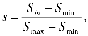
- T(s) is an interpolator function; P 0 is a preset minimum value of a pressure variation amplitude; P 1 is a preset maximum value of the pressure variation amplitude; g(p) is a function of the pressure variation amplitude; and p is a normalized value of acquired touch pressure, and

- With reference to the second aspect, in a fourth possible implementation manner, when the touch information is a touch area and touch pressure, the processing module is specifically configured to determine the area size of the feedback graph according to S = g(p)*f(s)/g(sp ), where:


- the S is the determined area size of the feedback graph; S 0 is a preset minimum area of the feedback graph in a case of an area parameter sp ; S 1 is a preset maximum area of the feedback graph in a case of the area parameter sp ;
- p is a normalized value of acquired touch pressure, and

- P min is preset minimum touch pressure, and P max is preset maximum touch pressure; T(p) is an interpolator function; F 0 is a preset minimum value of an area variation amplitude; F 1 is a preset maximum value of the area variation amplitude; f(s) is a function of the area variation amplitude; and s is a normalized value of acquired touch pressure, and

- According to a visual feedback method and apparatus for touch selection that are provided by embodiments of the present invention, touch information and a center point of touch are acquired, where the foregoing touch information is a touch area and/or touch pressure; an area size of a feedback graph is determined according to the foregoing touch information; and, by using the foregoing center point of touch as a center, the foregoing feedback graph is displayed according to the area size of the feedback graph, for a user to determine a touch position. Because a size of a feedback image is determined according to the touch information (a touch area and/or touch pressure), precision of visual feedback for touch selection can be improved.
- To describe the technical solutions in the embodiments of the present invention or in the prior art more clearly, the following briefly introduces the accompanying drawings required for describing the embodiments or the prior art. Apparently, the accompanying drawings in the following description show merely some embodiments of the present invention, and persons of ordinary skill in the art may still derive other drawings from these accompanying drawings without creative efforts.
-
FIG. 1 is a schematic flowchart of Embodiment 1 of a visual feedback method for touch selection according to the present invention; -
FIG. 2 is a display effect diagram of a feedback graph in a case of first touch pressure; -
FIG. 3 is a display effect diagram of a feedback graph in a case of second touch pressure; -
FIG. 4 is a schematic structural diagram of Embodiment 1 of a visual feedback apparatus for touch selection according to the present invention; and -
FIG. 5 is a schematic structural diagram ofEmbodiment 2 of a visual feedback apparatus for touch selection according to the present invention. - The following clearly and completely describes the technical solutions in the embodiments of the present invention with reference to the accompanying drawings in the embodiments of the present invention. Apparently, the described embodiments are merely a part rather than all of the embodiments of the present invention. All other embodiments obtained by persons of ordinary skill in the art based on the embodiments of the present invention without creative efforts shall fall within the protection scope of the present invention.
- In the present invention, a size of a feedback graph is determined with reference to a touch area and/or touch pressure, so as to improve precision of visual feedback for touch selection.
- The following describes technical solutions of the present invention in detail with reference to specific embodiments:
-
FIG. 1 is a schematic flowchart of Embodiment 1 of a visual feedback method for touch selection according to the present invention. As shown inFIG. 1 , the method in this embodiment includes the following steps:- S101. Acquire touch information and a center point of touch.
- The touch information is a touch area and/or touch pressure. The center point of touch is a center of a touch surface.
- S102. Determine an area size of a feedback graph according to the touch information.
- Specifically, as a first implementation manner, when the touch information is a touch area, the area size of the feedback graph may be determined according to the following formula:

- S is the determined area size of the feedback graph; S 0 is a preset minimum area of the feedback graph; S 1 is a preset maximum area of the feedback graph; and s is a normalized value of an acquired touch area, and

- A first type of interpolator function: T(s) = s
- A second type of interpolator function: T(s) = si , where i is an integer greater than or equal to. Preferably, i is usually set to 2, 3, 4, or 5.
- A third type of interpolator function: T(s) is determined by a cubic Bezier curve B(t), where the cubic Bezier curve is B(t) = P 0(1-t)3 + 3P 1(1 - t)2 t + 3P 2(1- t)t 2 + P 3 t 3, and P 0, P 1, P 2, and P 3 are four preset control points. For example, the control points are P 0 (0,0), P 1 (0.5,-0.05), P 2(0.6,1), and P 3(1,1).
- As a second implementation manner, when the touch information is touch pressure, the area size of the feedback graph may be determined according to the following formula:

- S is the determined area size of the feedback graph; S 0 is a preset minimum area of the feedback graph; S 1 is a preset maximum area of the feedback graph; p is a normalized value of acquired touch pressure; and T(p) is an interpolator function, and the interpolator function T(p) is any one of the following functions:

or
where i is an integer greater than or equal to, or - T(p) is determined by a cubic Bezier curve B(t), where the cubic Bezier curve is B(t) = P 0(1 - t)3 + 3P 1(1 - t)2 t + 3P 2(1 - t)t 2 + P3 t 3, and P 0, P 1, P 2, and P 3 are four preset control points.
- As a third implementation manner, when the touch information is a touch area and touch pressure, the area size of the feedback graph may be determined according to the following formula:

where:


- S is the determined area size of the feedback graph; S 0 is a preset minimum area of the feedback graph in a case of a pressure value ps ; S 1 is a preset maximum area of the feedback graph in a case of the pressure value ps ; f(s) is a determined area size of the feedback graph in a case of the pressure value ps ; s is a normalized value of an acquired touch area, and


- The interpolator function T(s) is any one of the following functions:

or
where i is an integer greater than or equal to, or - T(s) is determined by a cubic Bezier curve B(t), where the cubic Bezier curve is B(t) = P 0(1 - t)3 + 3P 1(1 - t)2 t + 3P 2(1 - t)t2 + P3t3 , and P 0, P 1, P 2, and P 3 are four preset control points.
- As a fourth implementation manner, when the touch information is a touch area and touch pressure, the area size of the feedback graph may be determined according to the following formula:

where:


- S is the determined area size of the feedback graph; S 0 is a preset minimum area of the feedback graph in a case of an area parameter sp ; S 1 is a preset maximum area of the feedback graph in a case of the area parameter sp ; p is a normalized value of acquired touch pressure, and


- The interpolator function T(p) is any one of the following functions:

or
where i is an integer greater than or equal to, or - T(p) is determined by a cubic Bezier curve B(t), where the cubic Bezier curve is B(t) = P 0(1 - t)3 + 3P1 (1-t) 2t + 3P2 (1 - t)t 2 + P 3 t 3, and P 0, P1, P2, and P 3 are four preset control points.
- Certainly, the foregoing several implementation manners are only examples for determining the area size of the feedback graph according to the touch information, and another implementation manner may also be used to determine the area size of the feedback graph according to the touch information, which is not limited by the present invention. That as long as an area size of a feedback graph is determined with reference to a touch area and/or touch pressure to improve precision of visual feedback shall fall within the protection scope of the present invention.
- S103. By using the foregoing center point of touch as a center, display the foregoing feedback graph according to an area size of the foregoing feedback image.
- Positions of a center point of the feedback graph and the center point of touch are the same. In the present invention, a size of the feedback graph is determined according to the touch information, and a form of the feedback graph is not presented in the present invention, for example, the feedback graph may be highlighted, or a feedback image is displayed in another color, or the feedback graph has a hatch pattern, which is not limited by the present invention.
- In this embodiment, touch information and a center point of touch are acquired, where the foregoing touch information is a touch area and/or touch pressure; an area size of a feedback graph is determined according to the foregoing touch information; and, by using the foregoing center point of touch as a center, the foregoing feedback graph is displayed according to the area size of the feedback graph, for a user to determine a touch position. Because a size of a feedback image is determined according to the touch information (a touch area and/or touch pressure), precision of visual feedback for touch selection can be improved, which better satisfies a user's requirement and improves user experience.
- The present invention further provides two accompanying drawings for comparison, so as to facilitate understanding of technical solutions of the present invention.
FIG. 2 is a display effect diagram of a feedback graph in a case of first touch pressure, andFIG. 3 is a display effect diagram of a feedback graph in a case of second touch pressure, where the first touch pressure is less than the second touch pressure. InFIG. 2 , region 1 is a feedback graph in a case of the first touch pressure in the prior art, andregion 2 is a feedback graph in a case of the first touch pressure in the present invention. InFIG. 3 ,region 3 is a feedback graph in a case of the second touch pressure in the prior art, andregion 4 is a feedback graph in a case of the second touch pressure in the present invention. It can be seen by comparingFIG. 2 withFIG. 3 that, in the prior art, a change of touch pressure does not affect a size of a feedback graph, that is, region 1 andregion 3 are of a same size. In the technical solutions of the present invention, the feedback graph in a case of the first touch pressure is smaller than the feedback graph in a case of the second touch pressure, that is,region 2 is smaller thanregion 4 in size. That is, an area size of a feedback graph in the present invention is determined according to the touch pressure.FIG. 2 andFIG. 3 are only examples of determining the area size of the feedback graph according to pressure. As can be seen fromFIG. 2 andFIG. 3 , visual feedback for touch selection can be improved by using the technical solutions of the present invention. -
FIG. 4 is a schematic structural diagram of Embodiment 1 of a visual feedback apparatus for touch selection according to the present invention. As shown inFIG. 4 , the apparatus in this embodiment includes an acquiringmodule 401, aprocessing module 402, and a displayingmodule 403. The acquiringmodule 401 is configured to acquire touch information and a center point of touch, where the touch information is a touch area and/or touch pressure; theprocessing module 402 is configured to determine an area size of a feedback graph according to the touch information; and the displayingmodule 403 is configured to display, by using the center point of touch as a center, the feedback graph according to an area size of the feedback image, for a user to determine a touch point. - The apparatus in this embodiment may be accordingly used to implement the technical solution in the method embodiment shown in
FIG. 1 . Implementation principles and technical effects of the apparatus are similar to those of the method embodiment, and details are not described herein again. - In the foregoing embodiment, when the touch information is a touch area, the
processing module 402 is specifically configured to determine the area size of the feedback graph according to S = S 0 + (S 1 - S 0) × T(s), where: - the S is the determined area size of the feedback graph; S 0 is a preset minimum area of the feedback graph; S 1 is a preset maximum area of the feedback graph; T(s) is an interpolator function; and s is a normalized value of an acquired touch area, and

- In the foregoing embodiment, the interpolator function T(s) is any one of the following functions:

or
where i is an integer greater than or equal to, or - T(s) is determined by a cubic Bezier curve B(t), where the cubic Bezier curve is B(t) = P 0(1 - t)3 + 3P 1(1 - t)2 t + 3P 2(1 - t)t 2 + P 3 t 3, and P 0, P 1, P 2, and P 3 are four preset control points.
- In the foregoing embodiment, when the touch information is touch pressure, the
processing module 402 is specifically configured to determine the area size of the feedback graph according to S = S 0 + (S 1 - S 0) × T(p), where: - the S is the determined area size of the feedback graph; S 0 is a preset minimum area of the feedback graph; S 1 is a preset maximum area of the feedback graph; T(p) is an interpolator function; and p is a normalized value of acquired touch pressure, and

- In the foregoing embodiment, the interpolator function T(p) is any one of the following functions:

or
where i is an integer greater than or equal to, or - T(p) is determined by a cubic Bezier curve B(t), where the cubic Bezier curve is B(t) = P 0(1 - t)3 + 3P 1(1 - t)2 t + 3P 2(1 - t)t 2 + P 3 t 3, and P 0 P 1, P 2, and P 3 are four preset control points.
- In the foregoing embodiment, when the touch information is a touch area and touch pressure, the
processing module 402 is specifically configured to determine the area size of the feedback graph according to S = f(s)*g(p)/g(ps ),
where:


the S is the determined area size of the feedback graph; S 0 is a preset minimum area of the feedback graph in a case of a pressure value ps ; S 1 is a preset maximum area of the feedback graph in a case of the pressure value ps ; f(s) is a determined area size of the feedback graph in a case of the pressure value ps ; s is a normalized value of an acquired touch area, and

- In the foregoing embodiment, the interpolator function T(s) is any one of the following functions:

or
where i is an integer greater than or equal to, or - T(s) is determined by a cubic Bezier curve B(t), where the cubic Bezier curve is B(t) = P 0(1 - t)3 + 3P 1(1 - t)2 t + 3P 2(1 - t)t 2 + P 3 t 3, and P 0, P 1, P 2, and P 3 are four preset control points.
- In the foregoing embodiment, when the touch information is a touch area and touch pressure, the
processing module 402 is specifically configured to determine the area size of the feedback graph according to S = g(p) * f(s) / g(sp ), where:


the S is the determined area size of the feedback graph; S 0 is a preset minimum area of the feedback graph in a case of an area parameter sp ; S 1 is a preset maximum area of the feedback graph in a case of the area parameter sp ; p is a normalized value of acquired touch pressure, and

- In the foregoing embodiment, the interpolator function T(p) is any one of the following functions:

or
where i is an integer greater than or equal to, or - T(p) is determined by a cubic Bezier curve B(t), where the cubic Bezier curve is B(t) = P 0(1 - t)3 + 3P 1(1 - t)2 t + 3P 2(1 - t)t 2 + P 3 t 3, and P 0, P 1, P 2, and P 3 are four preset control points.
-
FIG. 5 is a schematic structural diagram ofEmbodiment 2 of a visual feedback apparatus for touch selection according to the present invention. As shown inFIG. 5 , the apparatus in this embodiment includes anacquirer 501, aprocessor 502, and adisplay 503. Theacquirer 501 is configured to acquire touch information and a center point of touch, where the touch information is a touch area and/or touch pressure; theprocessor 502 is configured to determine an area size of a feedback graph according to the touch information; and thedisplay 503 is configured to display, by using the center point of touch as a center, the feedback graph according to an area size of the feedback image, for a user to determine a touch point. - The apparatus in this embodiment may be accordingly used to implement the technical solution in the method embodiment shown in
FIG. 1 . Implementation principles and technical effects of the apparatus are similar to those of the method embodiment, and details are not described herein again. - In the foregoing embodiment, when the touch information is a touch area, the
processor 502 is specifically configured to determine the area size of the feedback graph according to S = S 0 + (S 1 - S 0) × T(s), where: - the S is the determined area size of the feedback graph; S 0 is a preset minimum area of the feedback graph; S 1 is a preset maximum area of the feedback graph; T(s) is an interpolator function; and s is a normalized value of an acquired touch area, and

- In the foregoing embodiment, the interpolator function T(s) is any one of the following functions:

or
where i is an integer greater than or equal to, or - T(s) is determined by a cubic Bezier curve B(t), where the cubic Bezier curve is B(t) = P 0(1 - t)3 + 3P 1(1 - t)2 t + 3P 2(1 - t)t 2 + P 3 t 3, and P 0, P 1, P 2, and P 3 are four preset control points.
- In the foregoing embodiment, when the touch information is touch pressure, the
processor 502 is specifically configured to determine the area size of the feedback graph according to S = S 0 + (S1 - S 0) × T(p), where: - the S is the determined area size of the feedback graph; S 0 is a preset minimum area of the feedback graph; S 1 is a preset maximum area of the feedback graph; T(p) is an interpolator function; and p is a normalized value of acquired touch pressure, and

- In the foregoing embodiment, the interpolator function T(p) is any one of the following functions:

or
where i is an integer greater than or equal to, or - T(p) is determined by a cubic Bezier curve B(t), where the cubic Bezier curve is B(t) = P 0(1-t)3 + 3P 1(1 - t)2 t + 3P 2(1 - t)t 2 + P 3 t 3, and P 0, P 1, P 2, and P 3 are four preset control points.
- In the foregoing embodiment, when the touch information is a touch area and touch pressure, the
processor 502 is specifically configured to determine the area size of the feedback graph according to S = f(s) * g(p) / g(ps ),
where:


the S is the determined area size of the feedback graph; S 0 is a preset minimum area of the feedback graph in a case of a pressure value ps ; S 1 is a preset maximum area of the feedback graph in a case of the pressure value ps ; f(s) is a determined area size of the feedback graph in a case of the pressure value ps ; s is a normalized value of an acquired touch area, and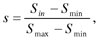

- In the foregoing embodiment, the interpolator function T(s) is any one of the following functions:
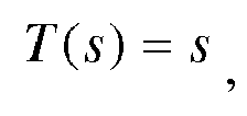
or
where i is an integer greater than or equal to, or - T(s) is determined by a cubic Bezier curve B(t), where the cubic Bezier curve is B(t) = P 0(1 - t)3 +3P 1(1 - t)2 t + 3P 2(1 - t)t 2 + P 3 t 3, and P 0, P1 , P 2, and P 3 are four preset control points.
- In the foregoing embodiment, when the touch information is a touch area and touch pressure, the
processor 502 is specifically configured to determine the area size of the feedback graph according to S = g(p) * f(s) / g(sp ), where:


the S is the determined area size of the feedback graph; S 0 is a preset minimum area of the feedback graph in a case of an area parameter sp ; S 1 is a preset maximum area of the feedback graph in a case of the area parameter sp ; p is a normalized value of acquired touch pressure, and

- In the foregoing embodiment, the interpolator function T(p) is any one of the following functions:

or
where i is an integer greater than or equal to, or - T(p) is determined by a cubic Bezier curve B(t), where the cubic Bezier curve is B(t) = P 0(1 - t)3 + 3P 1(1 - t)2 t + 3P 2(1 - t)t 2 + P 3 t 3, and P 0, P 1, P 2, and P 3 are four preset control points.
- Persons of ordinary skill in the art may understand that all or a part of the steps of the method embodiments may be implemented by a program instructing relevant hardware. The program may be stored in a computer readable storage medium. When the program runs, the steps of the method embodiments are performed. The foregoing storage medium includes any medium that can store program code, such as a ROM, a RAM, a magnetic disk, or an optical disc.
- Finally, it should be noted that the foregoing embodiments are merely intended for describing the technical solutions of the present invention other than limiting the present invention. Although the present invention is described in detail with reference to the foregoing embodiments, persons of ordinary skill in the art should understand that they may still make modifications to the technical solutions described in the foregoing embodiments or make equivalent replacements to some or all technical features thereof, without departing from the scope of the technical solutions of the embodiments of the present invention.
Claims (10)
- A visual feedback method for touch selection, comprising:acquiring touch information and a center point of touch, wherein the touch information is a touch area and/or touch pressure;determining an area size of a feedback graph according to the touch information; anddisplaying, by using the center point of touch as a center, the feedback graph according to the area size of the feedback graph, for a user to determine a touch position.
- The method according to claim 1, wherein when the touch information is a touch area, the determining an area size of a feedback graph according to the touch information comprises:determining the area size of the feedback graph according to S = S 0 + (S 1 - S 0) × T(s), wherein:the S is the determined area size of the feedback graph; S 0 is a preset minimum area of the feedback graph; S 1 is a preset maximum area of the feedback graph; T(s) is an interpolator function; and s is a normalized value of an acquired touch area, and

- The method according to claim 1, wherein when the touch information is touch pressure, the determining an area size of a feedback graph according to the touch information comprises:determining the area size of the feedback graph according to S = S 0 + (S 1 - S 0) × T(p), wherein:the S is the determined area size of the feedback graph; S 0 is a preset minimum area of the feedback graph; S 1 is a preset maximum area of the feedback graph; T(p) is an interpolator function; and p is a normalized value of acquired touch pressure, and

- The method according to claim 1, wherein when the touch information is a touch area and touch pressure, the determining an area size of a feedback graph according to the touch information comprises:determining the area size of the feedback graph according to S = f(s)*g(p)/g(ps ),wherein:


 the S is the determined area size of the feedback graph; S 0 is a preset minimum area of the feedback graph in a case of a pressure value ps ; S 1 is a preset maximum area of the feedback graph in a case of the pressure value ps ; f(s) is a determined area size of the feedback graph in a case of the pressure value ps ; s is a normalized value of an acquired touch area, and

- The method according to claim 1, wherein when the touch information is a touch area and touch pressure, the determining an area size of a feedback graph according to the touch information comprises:determining the area size of the feedback graph according to S = g(p)*f(s)/g(sp ), wherein:


 the S is the determined area size of the feedback graph; S 0 is a preset minimum area of the feedback graph in a case of an area parameter sp ; S 1 is a preset maximum area of the feedback graph in a case of the area parameter sp ; p is a normalized value of acquired touch pressure, and

- A visual feedback apparatus for touch selection, comprising:an acquiring module, configured to acquire touch information and a center point of touch, wherein the touch information is a touch area and/or touch pressure;a processing module, configured to determine an area size of a feedback graph according to the touch information; anda displaying module, configured to display, by using the center point of touch as a center, the feedback graph according to an area size of the feedback image, for a user to determine a touch position.
- The apparatus according to claim 6, wherein when the touch information is a touch area, the processing module is specifically configured to determine the area size of the feedback graph according to S = S 0 + (S 1 - S 0) × T(s), wherein:the S is the determined area size of the feedback graph; S 0 is a preset minimum area of the feedback graph; S 1 is a preset maximum area of the feedback graph; T(s) is an interpolator function; and s is a normalized value of an acquired touch area, and

- The apparatus according to claim 6, wherein when the touch information is touch pressure, the processing module is specifically configured to determine the area size of the feedback graph according to S = S 0 + (S 1 - S 0) × T(p), wherein:the S is the determined area size of the feedback graph; S 0 is a preset minimum area of the feedback graph; S 1 is a preset maximum area of the feedback graph; T(p) is an interpolator function; and p is a normalized value of acquired touch pressure, and

- The apparatus according to claim 6, wherein when the touch information is a touch area and touch pressure, the processing module is specifically configured to determine the area size of the feedback graph according to S = f(s)*g(p)/g(ps ),
wherein:

 the S is the determined area size of the feedback graph; S 0 is a preset minimum area of the feedback graph in a case of a pressure value ps ; S 1 is a preset maximum area of the feedback graph in a case of the pressure value ps ; f(s) is a determined area size of the feedback graph in a case of the pressure value ps ; s is a normalized value of an acquired touch area, and

- The apparatus according to claim 6, wherein when the touch information is a touch area and touch pressure, the processing module is specifically configured to determine the area size of the feedback graph according to S = g(p) * f(s)/g(sp ), wherein:


 the S is the determined area size of the feedback graph; S 0 is a preset minimum area of the feedback graph in a case of an area parameter sp ; S 1 is a preset maximum area of the feedback graph in a case of the area parameter sp ; p is a normalized value of acquired touch pressure, and
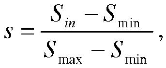
Applications Claiming Priority (2)
| Application Number | Priority Date | Filing Date | Title |
|---|---|---|---|
| CN201310594564.8A CN103631379B (en) | 2013-11-21 | 2013-11-21 | Visual feedback method and device for touch selection |
| PCT/CN2014/083471 WO2015074441A1 (en) | 2013-11-21 | 2014-07-31 | Visual feedback method and apparatus for touch selection |
Publications (3)
| Publication Number | Publication Date |
|---|---|
| EP2899610A1 true EP2899610A1 (en) | 2015-07-29 |
| EP2899610A4 EP2899610A4 (en) | 2015-11-04 |
| EP2899610B1 EP2899610B1 (en) | 2018-09-05 |
Family
ID=50212548
Family Applications (1)
| Application Number | Title | Priority Date | Filing Date |
|---|---|---|---|
| EP14812114.8A Active EP2899610B1 (en) | 2013-11-21 | 2014-07-31 | Visual feedback method and apparatus for touch selection |
Country Status (6)
| Country | Link |
|---|---|
| US (1) | US9612738B2 (en) |
| EP (1) | EP2899610B1 (en) |
| JP (1) | JP2017502384A (en) |
| KR (1) | KR101812043B1 (en) |
| CN (2) | CN107357510B (en) |
| WO (1) | WO2015074441A1 (en) |
Families Citing this family (7)
| Publication number | Priority date | Publication date | Assignee | Title |
|---|---|---|---|---|
| CN107357510B (en) | 2013-11-21 | 2021-06-04 | 华为终端有限公司 | Visual feedback method and device for touch selection |
| CN104598112B (en) | 2015-01-23 | 2019-01-18 | 小米科技有限责任公司 | Button interaction method and apparatus |
| US10459561B2 (en) * | 2015-07-09 | 2019-10-29 | Qualcomm Incorporated | Using capacitance to detect touch pressure |
| CN105159528A (en) * | 2015-08-27 | 2015-12-16 | 广东欧珀移动通信有限公司 | Picture content display method and mobile terminal |
| WO2018132947A1 (en) * | 2017-01-17 | 2018-07-26 | 廖建强 | Display control method and terminal |
| JP6947776B2 (en) * | 2019-04-26 | 2021-10-13 | 株式会社ソニー・インタラクティブエンタテインメント | Controller device, its control method, and program |
| CN115774514A (en) * | 2022-12-05 | 2023-03-10 | 北京字跳网络技术有限公司 | Method, device, device and storage medium for virtual object interaction |
Family Cites Families (17)
| Publication number | Priority date | Publication date | Assignee | Title |
|---|---|---|---|---|
| EP0595746A1 (en) * | 1992-10-29 | 1994-05-04 | International Business Machines Corporation | Method and system for input device pressure indication in a data processing system |
| US8760408B2 (en) * | 2004-08-02 | 2014-06-24 | Koninklijke Philips N.V. | Touch screen with pressure-dependent visual feedback |
| CN101414231B (en) * | 2007-10-17 | 2011-09-21 | 鸿富锦精密工业(深圳)有限公司 | Touch screen apparatus and image display method thereof |
| CN101498974A (en) * | 2008-01-28 | 2009-08-05 | 德信智能手机技术(北京)有限公司 | Feedback indication method for touch LCD screen |
| US20100220066A1 (en) * | 2009-02-27 | 2010-09-02 | Murphy Kenneth M T | Handheld electronic device having a touchscreen and a method of using a touchscreen of a handheld electronic device |
| CN101630223A (en) * | 2009-07-25 | 2010-01-20 | 深圳华为通信技术有限公司 | Method and terminal for adjusting interface |
| EP2302496A1 (en) * | 2009-09-10 | 2011-03-30 | Research In Motion Limited | Dynamic sizing of identifier on a touch-sensitive display |
| US20110057886A1 (en) * | 2009-09-10 | 2011-03-10 | Oliver Ng | Dynamic sizing of identifier on a touch-sensitive display |
| CN102043566A (en) * | 2009-10-19 | 2011-05-04 | 纬创资通股份有限公司 | Electronic device with touch panel and operation method thereof |
| US9116609B2 (en) * | 2011-03-30 | 2015-08-25 | Mckesson Financial Holdings | Methods, apparatuses and computer program products for generating regions of interest using gestures via a user interface |
| JP5957875B2 (en) * | 2011-12-26 | 2016-07-27 | ソニー株式会社 | Head mounted display |
| US8600450B2 (en) * | 2011-12-28 | 2013-12-03 | Sony Corporation | Receiving user input on a graphical user interface |
| JP6021335B2 (en) * | 2011-12-28 | 2016-11-09 | 任天堂株式会社 | Information processing program, information processing apparatus, information processing system, and information processing method |
| CN103294183B (en) * | 2012-03-05 | 2017-03-01 | 联想(北京)有限公司 | Terminal unit and its method that pressure is fed back |
| CN102662571B (en) * | 2012-03-26 | 2016-05-25 | 华为技术有限公司 | Method and the subscriber equipment of unlock screen protection |
| TWI459287B (en) * | 2012-04-20 | 2014-11-01 | Hon Hai Prec Ind Co Ltd | Touch control method and electronic system utilizing the same |
| CN107357510B (en) * | 2013-11-21 | 2021-06-04 | 华为终端有限公司 | Visual feedback method and device for touch selection |
-
2013
- 2013-11-21 CN CN201710326547.4A patent/CN107357510B/en active Active
- 2013-11-21 CN CN201310594564.8A patent/CN103631379B/en active Active
-
2014
- 2014-07-31 EP EP14812114.8A patent/EP2899610B1/en active Active
- 2014-07-31 JP JP2016533058A patent/JP2017502384A/en active Pending
- 2014-07-31 KR KR1020167014888A patent/KR101812043B1/en not_active Expired - Fee Related
- 2014-07-31 WO PCT/CN2014/083471 patent/WO2015074441A1/en not_active Ceased
- 2014-12-23 US US14/581,769 patent/US9612738B2/en active Active
Also Published As
| Publication number | Publication date |
|---|---|
| KR101812043B1 (en) | 2017-12-26 |
| WO2015074441A1 (en) | 2015-05-28 |
| US9612738B2 (en) | 2017-04-04 |
| CN103631379B (en) | 2017-05-31 |
| US20150138124A1 (en) | 2015-05-21 |
| CN107357510A (en) | 2017-11-17 |
| CN103631379A (en) | 2014-03-12 |
| CN107357510B (en) | 2021-06-04 |
| KR20160079871A (en) | 2016-07-06 |
| EP2899610B1 (en) | 2018-09-05 |
| EP2899610A4 (en) | 2015-11-04 |
| JP2017502384A (en) | 2017-01-19 |
Similar Documents
| Publication | Publication Date | Title |
|---|---|---|
| US9612738B2 (en) | Visual feedback method and apparatus for touch selection | |
| EP3901756B1 (en) | Electronic device including touch sensitive display and method for operating the same | |
| US10318042B2 (en) | Controlling method of foldable screen and electronic device | |
| EP2618295A1 (en) | Terminal and schedule displaying method | |
| CN103176702B (en) | A kind of display of form category information, method of operating being applied to B/S structure | |
| CN106648337A (en) | Method and apparatus for displaying contents in display list, and electronic device | |
| CN104238783B (en) | The control method and device of a kind of touch-screen | |
| US20130321350A1 (en) | Virtual ruler for stylus input | |
| EP2902897A1 (en) | Word processing method and apparatus for touchscreen intelligent device | |
| US10579254B2 (en) | Method and apparatus for realizing human-machine interaction | |
| CN103095923A (en) | Short message display method of mobile communication terminal | |
| US20150378521A1 (en) | Breadth-first menu system for mobile applications | |
| US20140195900A1 (en) | Computer readable medium for enhanced display of digital text | |
| US20160026244A1 (en) | Gui device | |
| US20150253980A1 (en) | Information processing method and electronic device | |
| US10067647B2 (en) | Information processing method and deformable electronic device | |
| CN106293446B (en) | Display method and display device | |
| EP2669783A1 (en) | Virtual ruler for stylus input | |
| JP6160115B2 (en) | Information processing apparatus, presentation material optimization method, and program | |
| EP2853998B1 (en) | Touch positioning method, device and touch terminal | |
| CN103870154B (en) | Dialogue input and display device | |
| EP2846232A1 (en) | Method and device for unlocking touch screen | |
| US10614152B2 (en) | Exposing formatting properties of content for accessibility | |
| CN104461363A (en) | Method and device for adjusting character size on touch screen device | |
| CN107967091A (en) | A kind of man-machine interaction method and the computing device for human-computer interaction |
Legal Events
| Date | Code | Title | Description |
|---|---|---|---|
| PUAI | Public reference made under article 153(3) epc to a published international application that has entered the european phase |
Free format text: ORIGINAL CODE: 0009012 |
|
| 17P | Request for examination filed |
Effective date: 20141222 |
|
| AK | Designated contracting states |
Kind code of ref document: A1 Designated state(s): AL AT BE BG CH CY CZ DE DK EE ES FI FR GB GR HR HU IE IS IT LI LT LU LV MC MK MT NL NO PL PT RO RS SE SI SK SM TR |
|
| AX | Request for extension of the european patent |
Extension state: BA ME |
|
| RIC1 | Information provided on ipc code assigned before grant |
Ipc: G06F 3/0488 20130101AFI20150924BHEP Ipc: G06F 3/041 20060101ALI20150924BHEP |
|
| RA4 | Supplementary search report drawn up and despatched (corrected) |
Effective date: 20151001 |
|
| DAX | Request for extension of the european patent (deleted) | ||
| RAP1 | Party data changed (applicant data changed or rights of an application transferred) |
Owner name: HUAWEI DEVICE (DONGGUAN) CO., LTD. |
|
| REG | Reference to a national code |
Ref country code: DE Ref legal event code: R079 Ref document number: 602014031925 Country of ref document: DE Free format text: PREVIOUS MAIN CLASS: G06F0003010000 Ipc: G06F0003048800 |
|
| GRAP | Despatch of communication of intention to grant a patent |
Free format text: ORIGINAL CODE: EPIDOSNIGR1 |
|
| STAA | Information on the status of an ep patent application or granted ep patent |
Free format text: STATUS: GRANT OF PATENT IS INTENDED |
|
| RIC1 | Information provided on ipc code assigned before grant |
Ipc: G06F 3/0488 20130101AFI20180126BHEP Ipc: G06F 3/041 20060101ALI20180126BHEP |
|
| INTG | Intention to grant announced |
Effective date: 20180219 |
|
| GRAS | Grant fee paid |
Free format text: ORIGINAL CODE: EPIDOSNIGR3 |
|
| GRAA | (expected) grant |
Free format text: ORIGINAL CODE: 0009210 |
|
| STAA | Information on the status of an ep patent application or granted ep patent |
Free format text: STATUS: THE PATENT HAS BEEN GRANTED |
|
| AK | Designated contracting states |
Kind code of ref document: B1 Designated state(s): AL AT BE BG CH CY CZ DE DK EE ES FI FR GB GR HR HU IE IS IT LI LT LU LV MC MK MT NL NO PL PT RO RS SE SI SK SM TR |
|
| REG | Reference to a national code |
Ref country code: GB Ref legal event code: FG4D |
|
| REG | Reference to a national code |
Ref country code: CH Ref legal event code: EP |
|
| REG | Reference to a national code |
Ref country code: AT Ref legal event code: REF Ref document number: 1038606 Country of ref document: AT Kind code of ref document: T Effective date: 20180915 |
|
| REG | Reference to a national code |
Ref country code: DE Ref legal event code: R096 Ref document number: 602014031925 Country of ref document: DE |
|
| REG | Reference to a national code |
Ref country code: IE Ref legal event code: FG4D |
|
| REG | Reference to a national code |
Ref country code: NL Ref legal event code: FP |
|
| REG | Reference to a national code |
Ref country code: LT Ref legal event code: MG4D |
|
| PG25 | Lapsed in a contracting state [announced via postgrant information from national office to epo] |
Ref country code: SE Free format text: LAPSE BECAUSE OF FAILURE TO SUBMIT A TRANSLATION OF THE DESCRIPTION OR TO PAY THE FEE WITHIN THE PRESCRIBED TIME-LIMIT Effective date: 20180905 Ref country code: NO Free format text: LAPSE BECAUSE OF FAILURE TO SUBMIT A TRANSLATION OF THE DESCRIPTION OR TO PAY THE FEE WITHIN THE PRESCRIBED TIME-LIMIT Effective date: 20181205 Ref country code: GR Free format text: LAPSE BECAUSE OF FAILURE TO SUBMIT A TRANSLATION OF THE DESCRIPTION OR TO PAY THE FEE WITHIN THE PRESCRIBED TIME-LIMIT Effective date: 20181206 Ref country code: RS Free format text: LAPSE BECAUSE OF FAILURE TO SUBMIT A TRANSLATION OF THE DESCRIPTION OR TO PAY THE FEE WITHIN THE PRESCRIBED TIME-LIMIT Effective date: 20180905 Ref country code: FI Free format text: LAPSE BECAUSE OF FAILURE TO SUBMIT A TRANSLATION OF THE DESCRIPTION OR TO PAY THE FEE WITHIN THE PRESCRIBED TIME-LIMIT Effective date: 20180905 Ref country code: BG Free format text: LAPSE BECAUSE OF FAILURE TO SUBMIT A TRANSLATION OF THE DESCRIPTION OR TO PAY THE FEE WITHIN THE PRESCRIBED TIME-LIMIT Effective date: 20181205 Ref country code: LT Free format text: LAPSE BECAUSE OF FAILURE TO SUBMIT A TRANSLATION OF THE DESCRIPTION OR TO PAY THE FEE WITHIN THE PRESCRIBED TIME-LIMIT Effective date: 20180905 |
|
| REG | Reference to a national code |
Ref country code: AT Ref legal event code: MK05 Ref document number: 1038606 Country of ref document: AT Kind code of ref document: T Effective date: 20180905 |
|
| PG25 | Lapsed in a contracting state [announced via postgrant information from national office to epo] |
Ref country code: AL Free format text: LAPSE BECAUSE OF FAILURE TO SUBMIT A TRANSLATION OF THE DESCRIPTION OR TO PAY THE FEE WITHIN THE PRESCRIBED TIME-LIMIT Effective date: 20180905 Ref country code: LV Free format text: LAPSE BECAUSE OF FAILURE TO SUBMIT A TRANSLATION OF THE DESCRIPTION OR TO PAY THE FEE WITHIN THE PRESCRIBED TIME-LIMIT Effective date: 20180905 Ref country code: HR Free format text: LAPSE BECAUSE OF FAILURE TO SUBMIT A TRANSLATION OF THE DESCRIPTION OR TO PAY THE FEE WITHIN THE PRESCRIBED TIME-LIMIT Effective date: 20180905 |
|
| PG25 | Lapsed in a contracting state [announced via postgrant information from national office to epo] |
Ref country code: EE Free format text: LAPSE BECAUSE OF FAILURE TO SUBMIT A TRANSLATION OF THE DESCRIPTION OR TO PAY THE FEE WITHIN THE PRESCRIBED TIME-LIMIT Effective date: 20180905 Ref country code: PL Free format text: LAPSE BECAUSE OF FAILURE TO SUBMIT A TRANSLATION OF THE DESCRIPTION OR TO PAY THE FEE WITHIN THE PRESCRIBED TIME-LIMIT Effective date: 20180905 Ref country code: IS Free format text: LAPSE BECAUSE OF FAILURE TO SUBMIT A TRANSLATION OF THE DESCRIPTION OR TO PAY THE FEE WITHIN THE PRESCRIBED TIME-LIMIT Effective date: 20190105 Ref country code: ES Free format text: LAPSE BECAUSE OF FAILURE TO SUBMIT A TRANSLATION OF THE DESCRIPTION OR TO PAY THE FEE WITHIN THE PRESCRIBED TIME-LIMIT Effective date: 20180905 Ref country code: CZ Free format text: LAPSE BECAUSE OF FAILURE TO SUBMIT A TRANSLATION OF THE DESCRIPTION OR TO PAY THE FEE WITHIN THE PRESCRIBED TIME-LIMIT Effective date: 20180905 Ref country code: RO Free format text: LAPSE BECAUSE OF FAILURE TO SUBMIT A TRANSLATION OF THE DESCRIPTION OR TO PAY THE FEE WITHIN THE PRESCRIBED TIME-LIMIT Effective date: 20180905 Ref country code: AT Free format text: LAPSE BECAUSE OF FAILURE TO SUBMIT A TRANSLATION OF THE DESCRIPTION OR TO PAY THE FEE WITHIN THE PRESCRIBED TIME-LIMIT Effective date: 20180905 Ref country code: IT Free format text: LAPSE BECAUSE OF FAILURE TO SUBMIT A TRANSLATION OF THE DESCRIPTION OR TO PAY THE FEE WITHIN THE PRESCRIBED TIME-LIMIT Effective date: 20180905 |
|
| PG25 | Lapsed in a contracting state [announced via postgrant information from national office to epo] |
Ref country code: SK Free format text: LAPSE BECAUSE OF FAILURE TO SUBMIT A TRANSLATION OF THE DESCRIPTION OR TO PAY THE FEE WITHIN THE PRESCRIBED TIME-LIMIT Effective date: 20180905 Ref country code: SM Free format text: LAPSE BECAUSE OF FAILURE TO SUBMIT A TRANSLATION OF THE DESCRIPTION OR TO PAY THE FEE WITHIN THE PRESCRIBED TIME-LIMIT Effective date: 20180905 Ref country code: PT Free format text: LAPSE BECAUSE OF FAILURE TO SUBMIT A TRANSLATION OF THE DESCRIPTION OR TO PAY THE FEE WITHIN THE PRESCRIBED TIME-LIMIT Effective date: 20190105 |
|
| REG | Reference to a national code |
Ref country code: DE Ref legal event code: R097 Ref document number: 602014031925 Country of ref document: DE |
|
| RAP2 | Party data changed (patent owner data changed or rights of a patent transferred) |
Owner name: HUAWEI DEVICE CO., LTD. |
|
| REG | Reference to a national code |
Ref country code: NL Ref legal event code: HC Owner name: HUAWEI DEVICE CO., LTD.; CN Free format text: DETAILS ASSIGNMENT: CHANGE OF OWNER(S), CHANGE OF OWNER(S) NAME; FORMER OWNER NAME: HUAWEI DEVICE (DONGGUAN) CO., LTD. Effective date: 20190514 |
|
| REG | Reference to a national code |
Ref country code: DE Ref legal event code: R081 Ref document number: 602014031925 Country of ref document: DE Owner name: HUAWEI DEVICE CO., LTD., DONGGUAN, CN Free format text: FORMER OWNER: HUAWEI DEVICE (DONGGUAN) CO., LTD., DONGGUAN, GUANGDONG, CN |
|
| PLBE | No opposition filed within time limit |
Free format text: ORIGINAL CODE: 0009261 |
|
| STAA | Information on the status of an ep patent application or granted ep patent |
Free format text: STATUS: NO OPPOSITION FILED WITHIN TIME LIMIT |
|
| PG25 | Lapsed in a contracting state [announced via postgrant information from national office to epo] |
Ref country code: DK Free format text: LAPSE BECAUSE OF FAILURE TO SUBMIT A TRANSLATION OF THE DESCRIPTION OR TO PAY THE FEE WITHIN THE PRESCRIBED TIME-LIMIT Effective date: 20180905 |
|
| 26N | No opposition filed |
Effective date: 20190606 |
|
| PG25 | Lapsed in a contracting state [announced via postgrant information from national office to epo] |
Ref country code: SI Free format text: LAPSE BECAUSE OF FAILURE TO SUBMIT A TRANSLATION OF THE DESCRIPTION OR TO PAY THE FEE WITHIN THE PRESCRIBED TIME-LIMIT Effective date: 20180905 |
|
| PG25 | Lapsed in a contracting state [announced via postgrant information from national office to epo] |
Ref country code: MC Free format text: LAPSE BECAUSE OF FAILURE TO SUBMIT A TRANSLATION OF THE DESCRIPTION OR TO PAY THE FEE WITHIN THE PRESCRIBED TIME-LIMIT Effective date: 20180905 |
|
| REG | Reference to a national code |
Ref country code: CH Ref legal event code: PL |
|
| PG25 | Lapsed in a contracting state [announced via postgrant information from national office to epo] |
Ref country code: TR Free format text: LAPSE BECAUSE OF FAILURE TO SUBMIT A TRANSLATION OF THE DESCRIPTION OR TO PAY THE FEE WITHIN THE PRESCRIBED TIME-LIMIT Effective date: 20180905 |
|
| REG | Reference to a national code |
Ref country code: BE Ref legal event code: MM Effective date: 20190731 |
|
| PG25 | Lapsed in a contracting state [announced via postgrant information from national office to epo] |
Ref country code: BE Free format text: LAPSE BECAUSE OF NON-PAYMENT OF DUE FEES Effective date: 20190731 Ref country code: LU Free format text: LAPSE BECAUSE OF NON-PAYMENT OF DUE FEES Effective date: 20190731 Ref country code: LI Free format text: LAPSE BECAUSE OF NON-PAYMENT OF DUE FEES Effective date: 20190731 Ref country code: CH Free format text: LAPSE BECAUSE OF NON-PAYMENT OF DUE FEES Effective date: 20190731 |
|
| PG25 | Lapsed in a contracting state [announced via postgrant information from national office to epo] |
Ref country code: IE Free format text: LAPSE BECAUSE OF NON-PAYMENT OF DUE FEES Effective date: 20190731 |
|
| PG25 | Lapsed in a contracting state [announced via postgrant information from national office to epo] |
Ref country code: CY Free format text: LAPSE BECAUSE OF FAILURE TO SUBMIT A TRANSLATION OF THE DESCRIPTION OR TO PAY THE FEE WITHIN THE PRESCRIBED TIME-LIMIT Effective date: 20180905 |
|
| PG25 | Lapsed in a contracting state [announced via postgrant information from national office to epo] |
Ref country code: HU Free format text: LAPSE BECAUSE OF FAILURE TO SUBMIT A TRANSLATION OF THE DESCRIPTION OR TO PAY THE FEE WITHIN THE PRESCRIBED TIME-LIMIT; INVALID AB INITIO Effective date: 20140731 Ref country code: MT Free format text: LAPSE BECAUSE OF FAILURE TO SUBMIT A TRANSLATION OF THE DESCRIPTION OR TO PAY THE FEE WITHIN THE PRESCRIBED TIME-LIMIT Effective date: 20180905 |
|
| PG25 | Lapsed in a contracting state [announced via postgrant information from national office to epo] |
Ref country code: MK Free format text: LAPSE BECAUSE OF FAILURE TO SUBMIT A TRANSLATION OF THE DESCRIPTION OR TO PAY THE FEE WITHIN THE PRESCRIBED TIME-LIMIT Effective date: 20180905 |
|
| PGFP | Annual fee paid to national office [announced via postgrant information from national office to epo] |
Ref country code: NL Payment date: 20240613 Year of fee payment: 11 |
|
| PGFP | Annual fee paid to national office [announced via postgrant information from national office to epo] |
Ref country code: FR Payment date: 20240611 Year of fee payment: 11 |
|
| PGFP | Annual fee paid to national office [announced via postgrant information from national office to epo] |
Ref country code: DE Payment date: 20240604 Year of fee payment: 11 |
|
| P01 | Opt-out of the competence of the unified patent court (upc) registered |
Free format text: CASE NUMBER: UPC_APP_120494/2023 Effective date: 20230510 |
|
| PGFP | Annual fee paid to national office [announced via postgrant information from national office to epo] |
Ref country code: GB Payment date: 20250612 Year of fee payment: 12 |
|
| REG | Reference to a national code |
Ref country code: DE Ref legal event code: R119 Ref document number: 602014031925 Country of ref document: DE |
|
| REG | Reference to a national code |
Ref country code: NL Ref legal event code: MM Effective date: 20250801 |
|
| PG25 | Lapsed in a contracting state [announced via postgrant information from national office to epo] |
Ref country code: DE Free format text: LAPSE BECAUSE OF NON-PAYMENT OF DUE FEES Effective date: 20260203 |
|
| PG25 | Lapsed in a contracting state [announced via postgrant information from national office to epo] |
Ref country code: NL Free format text: LAPSE BECAUSE OF NON-PAYMENT OF DUE FEES Effective date: 20250801 |
|
| PG25 | Lapsed in a contracting state [announced via postgrant information from national office to epo] |
Ref country code: FR Free format text: LAPSE BECAUSE OF NON-PAYMENT OF DUE FEES Effective date: 20250731 |