EP2899580A1 - Endoscope objective lens - Google Patents
Endoscope objective lens Download PDFInfo
- Publication number
- EP2899580A1 EP2899580A1 EP13839022.4A EP13839022A EP2899580A1 EP 2899580 A1 EP2899580 A1 EP 2899580A1 EP 13839022 A EP13839022 A EP 13839022A EP 2899580 A1 EP2899580 A1 EP 2899580A1
- Authority
- EP
- European Patent Office
- Prior art keywords
- lens
- lens group
- endoscope objective
- objective lens
- expression
- Prior art date
- Legal status (The legal status is an assumption and is not a legal conclusion. Google has not performed a legal analysis and makes no representation as to the accuracy of the status listed.)
- Granted
Links
Images











Classifications
-
- G—PHYSICS
- G02—OPTICS
- G02B—OPTICAL ELEMENTS, SYSTEMS OR APPARATUS
- G02B9/00—Optical objectives characterised both by the number of the components and their arrangements according to their sign, i.e. + or -
- G02B9/12—Optical objectives characterised both by the number of the components and their arrangements according to their sign, i.e. + or - having three components only
- G02B9/14—Optical objectives characterised both by the number of the components and their arrangements according to their sign, i.e. + or - having three components only arranged + - +
-
- A—HUMAN NECESSITIES
- A61—MEDICAL OR VETERINARY SCIENCE; HYGIENE
- A61B—DIAGNOSIS; SURGERY; IDENTIFICATION
- A61B1/00—Instruments for performing medical examinations of the interior of cavities or tubes of the body by visual or photographical inspection, e.g. endoscopes; Illuminating arrangements therefor
- A61B1/00163—Optical arrangements
- A61B1/00188—Optical arrangements with focusing or zooming features
-
- G—PHYSICS
- G02—OPTICS
- G02B—OPTICAL ELEMENTS, SYSTEMS OR APPARATUS
- G02B23/00—Telescopes, e.g. binoculars; Periscopes; Instruments for viewing the inside of hollow bodies; Viewfinders; Optical aiming or sighting devices
- G02B23/24—Instruments or systems for viewing the inside of hollow bodies, e.g. fibrescopes
- G02B23/2407—Optical details
- G02B23/2423—Optical details of the distal end
- G02B23/243—Objectives for endoscopes
- G02B23/2438—Zoom objectives
-
- G—PHYSICS
- G02—OPTICS
- G02B—OPTICAL ELEMENTS, SYSTEMS OR APPARATUS
- G02B15/00—Optical objectives with means for varying the magnification
- G02B15/14—Optical objectives with means for varying the magnification by axial movement of one or more lenses or groups of lenses relative to the image plane for continuously varying the equivalent focal length of the objective
- G02B15/16—Optical objectives with means for varying the magnification by axial movement of one or more lenses or groups of lenses relative to the image plane for continuously varying the equivalent focal length of the objective with interdependent non-linearly related movements between one lens or lens group, and another lens or lens group
- G02B15/163—Optical objectives with means for varying the magnification by axial movement of one or more lenses or groups of lenses relative to the image plane for continuously varying the equivalent focal length of the objective with interdependent non-linearly related movements between one lens or lens group, and another lens or lens group having a first movable lens or lens group and a second movable lens or lens group, both in front of a fixed lens or lens group
- G02B15/167—Optical objectives with means for varying the magnification by axial movement of one or more lenses or groups of lenses relative to the image plane for continuously varying the equivalent focal length of the objective with interdependent non-linearly related movements between one lens or lens group, and another lens or lens group having a first movable lens or lens group and a second movable lens or lens group, both in front of a fixed lens or lens group having an additional fixed front lens or group of lenses
- G02B15/173—Optical objectives with means for varying the magnification by axial movement of one or more lenses or groups of lenses relative to the image plane for continuously varying the equivalent focal length of the objective with interdependent non-linearly related movements between one lens or lens group, and another lens or lens group having a first movable lens or lens group and a second movable lens or lens group, both in front of a fixed lens or lens group having an additional fixed front lens or group of lenses arranged +-+
Definitions
- the present invention relates to an endoscope objective lens, in particular, to an endoscope variable-magnification objective lens that is used for an endoscope capable of performing magnifying observation in addition to normal observation.
- endoscopes capable of performing magnifying observation have been in high demand in the medical field in order to make accurate diagnoses of lesions.
- Magnifying observation with an endoscope is performed such that some lenses in the objective lens are moved to change the focal distance, thus changing the observation distance.
- the lenses are moved to change the focal distance, thereby making it possible to focus the endoscope at a distance of up to about 2 mm.
- This configuration of lenses is generally called a focusing lens, which is different from zoom lenses that are used in cameras.
- endoscope optical systems that have a configuration formed of three lens groups, namely, positive, negative, and positive lens groups, and that move the second lens group, thereby performing variable magnification and focusing, are disclosed in PTLs 1 and 2.
- the endoscope optical systems disclosed in PTLs 1 and 2 had the following problems. That is to say, in both of the endoscope optical systems disclosed in PTLs 1 and 2, magnifying observation is allowed by moving the second lens group; however, the power of the second lens group is high, and a change in magnification with respect to the lens movement distance is large. Therefore, the position adjustment of the second lens group becomes difficult. More specifically, manufacturing errors tend to occur whereby, for magnifying observation, although the magnification can be ensured, the depth of field is narrowed; or although the depth of field can be ensured, the magnification does not reach a desired level.
- An object of the present invention is to provide an endoscope objective lens for which manufacturing errors are suppressed, that is provided with a variable magnification function, and that can perform good observation with aberrations appropriately corrected.
- the present invention provides the following solutions.
- the present invention provides an endoscope objective lens including, in order from an object side, a positive first lens group, a negative second lens group, and a positive third lens group, in which the first lens group has a meniscus lens; and a normal observation state (wide angle end) and a magnifying observation state (telephoto end) can be switched between by moving the second lens group on an optical axis, and the following conditions are satisfied; - 9 ⁇ f 2 / f W ⁇ - 3.5 4.5 ⁇ f M / f W ⁇ 50 where f M represents a focal distance of the meniscus lens, f w represents an entire focal distance for the normal observation, and f 2 represents a focal distance of the second lens group.
- Expression (1) relates to the position adjustment sensitivity of the second lens group. If the value of f 2 /f w falls below the lower limit of Expression (1), manufacturing errors are increased. If the position adjustment sensitivity is high, the deviation from the designed objective lens is greater, thus causing a problem in that, although the magnification can be ensured, the depth of field is narrowed or a problem in that, although the depth of field can be ensured, the magnification does not reach a desired level, for example. On the other hand, if the value of f 2 /f w exceeds the upper limit of Expression (1), the position adjustment sensitivity is relaxed, but it becomes difficult to ensure sufficient magnification.
- Expression (2) relates to successful correction of the aberrations, in particular, chromatic aberration of magnification. If the value of
- the second lens group may consist of a joined lens that is formed of a concave lens having a high refractive index and a convex lens having a low refractive index; and a lens surface of the second lens group that is located closest to an object and a lens surface thereof that is located closest to an image may each have a planar shape.
- the second lens group may be provided, for example, with a movement mechanism such as an actuator to be connected to a lens frame for holding a movable lens group to give a driving force to the lens frame.
- a movement mechanism such as an actuator to be connected to a lens frame for holding a movable lens group to give a driving force to the lens frame.
- eccentricity and tilt are caused by a clearance between the movement mechanism and the lens frame. Therefore, the levels of eccentricity and tilt caused in the lenses of the second lens group are increased compared with those caused in the lenses of the first lens group and in the lenses of the third lens group, to which a movement mechanism is not connected.
- the second lens group is made to consist of the joined lens, which is formed of the concave lens having a high refractive index and the convex lens having a low refractive index, thereby forming it into a parallel plate shape as a whole; therefore, it is possible to hamper the occurrence of eccentricity and tilt and to exert a negative refractive index as power.
- the second lens group In order to reduce the load imposed on the movement mechanism, it is desirable that the second lens group have a small lens diameter. With a small diameter, processing for a meniscus lens is difficult, and the cost tends to be increased, as a result. From this point of view, it is desirable to provide the configuration of the present invention.
- an aperture stop that is moved together with the second lens group may be further included.
- the f-number is increased as much as possible to narrow the aperture stop close to the diffraction limit, thereby ensuring the depth of field.
- the f-number for the normal observation becomes small, thus making it difficult to ensure a sufficient depth of field. Therefore, by moving the aperture stop and the lens at the same time, it is possible to reduce a change in f-number between the normal observation and the magnifying observation.
- conditional expression may be satisfied; - 0.77 ⁇ f 3 / f 2 ⁇ - 0.34 where f 3 represents a focal distance of the third lens group.
- conditional expression may be satisfied; - 4.5 ⁇ f 2 / f 1 ⁇ - 2.38 where f 1 represents a focal distance of the first lens group.
- the present invention affords an advantage in that good observation with aberrations appropriately corrected can be performed.
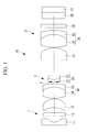
- an endoscope objective lens 10 of this embodiment includes, in order from the object side, a positive first lens group 1, an aperture stop 4, a negative second lens group 2, and a positive third lens group 3.
- the first lens group 1 consists of, in order from the object side, a planoconcave lens 11 whose flat surface faces the object side, a parallel plate 12, a meniscus lens 13 whose concave surface faces the object side, and a joined lens 16 that is formed of a biconvex lens 14 and a concave lens 15.
- the second lens group 2 consists of a joined lens 23 that is formed of a concave lens 21 having a high refractive index and a convex lens 22 having a low refractive index.
- a lens surface (r10 shown in Fig. 3 ) of the second lens group 2 that is located closest to an object and a lens surface (r12 shown in Fig. 3 ) thereof that is located closest to an image each have a planar shape.
- the third lens group 3 consists of a planoconvex lens 31 whose flat surface faces the object side; a joined lens 34 that is formed of a biconvex lens 32 and a concave lens 33; and three parallel plates 35, 36, and 37.
- the second lens group 2 of this embodiment is provided so as to be capable of being moved on an optical axis together with the aperture stop 4.
- the joined lens 23 movable lens group
- the joined lens 23 which is formed of the concave lens 21 and the convex lens 22, is held by a lens frame (not shown), and an actuator (movement mechanism, not shown) for giving a driving force to the lens frame is connected to the lens frame. Then, the joined lens 23 is moved on the optical axis together with the lens frame through actuation of the actuator.
- eccentricity and tilt are caused by a clearance between the lenses and the lens frame. Therefore, the levels of eccentricity and tilt caused in the lenses of the second lens group 2, to which the movement mechanism is connected, are increased compared with those caused in the lenses of the first lens group 1 and in the lenses of the third lens group 3, to which a movement mechanism is not connected.
- the second lens group 2 is made to consist of the joined lens 23, which is formed of the concave lens 21 having a high refractive index and the convex lens 22 having a low refractive index, thereby forming it into a parallel plate shape as a whole; therefore, it is possible to hamper the occurrence of eccentricity and tilt and to exert a negative refractive index as power.
- the second lens group 2 In order to reduce the load imposed on the movement mechanism, it is desirable that the second lens group 2 have a small lens diameter. With a small diameter, processing for a meniscus lens is difficult, and the cost tends to be increased, as a result. Therefore, it is desirable to provide the configuration of the second lens group 2 of this embodiment.
- the endoscope objective lens 10 can be switched between a normal observation state (wide angle end) and a magnifying observation state (telephoto end) by moving the second lens group 2 on the optical axis in the axial direction. For example, the endoscope objective lens 10 enters the normal observation state when the second lens group 2 is moved on the optical axis toward the object, as shown in Fig. 1 , and enters the magnifying observation state when the second lens group 2 is moved on the optical axis toward the image, as shown in Fig. 2 .
- the f-number is increased as much as possible to narrow the aperture stop 4 close to the diffraction limit, thereby ensuring the depth of field.
- the f-number for the normal observation becomes small, thus making it difficult to ensure a sufficient depth of field. Therefore, by moving the aperture stop 4 and the second lens group 2 at the same time, it is possible to reduce a change in f-number between the normal observation and the magnifying observation.
- the endoscope objective lens 10 satisfies the following conditional expressions; - 9 ⁇ f 2 / f W ⁇ - 3.5 4.5 ⁇ f M / f W ⁇ 50 where f M represents the focal distance of the meniscus lens 13, f w represents the entire focal distance for the normal observation, and f 2 represents the focal distance of the second lens group 2.
- Expression (1) relates to the position adjustment sensitivity of the second lens group 2. If the value of f 2 /f w falls below the lower limit of Expression (1), manufacturing errors are increased. If the position adjustment sensitivity is high, the deviation from the designed objective lens is greater, thus causing a problem in that, although the magnification can be ensured, the depth of field is narrowed or a problem in that, although the depth of field can be ensured, the magnification does not reach a desired level, for example. On the other hand, if the value of f 2 /f w exceeds the upper limit of Expression (1), the position adjustment sensitivity is relaxed, but it becomes difficult to ensure sufficient magnification.
- Expression (2) relates to successful correction of the aberrations, in particular, chromatic aberration of magnification. If the value of
- the endoscope objective lens 10 satisfies the following conditional expression; - 0.77 ⁇ f 3 / f 2 ⁇ - 0.34 where f 3 represents the focal distance of the third lens group 3.
- the endoscope objective lens 10 satisfies the following conditional expression; - 4.5 ⁇ f 2 / f 1 ⁇ - 2.38 where f 1 represents the focal distance of the first lens group 1.
- the endoscope objective lens 10 satisfies the following conditional expression. 1.5 ⁇ f 3 / f 1 ⁇ 2.5
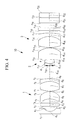
- FIG. 3 shows a state in which the second lens group 2 has been moved toward the object, that is, a normal observation state.
- Fig. 4 shows a state in which the second lens group 2 has been moved toward the image, that is, a magnifying observation state.
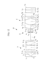
- r 1 to r 9 denote surfaces of the lenses constituting the positive first lens group 1
- r 10 to r 12 denote surfaces of the lenses constituting the negative second lens group 2
- r 13 to r 22 denote surfaces of the lenses constituting the positive third lens group 3.
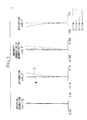
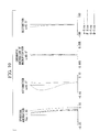
- Figs. 7 , 8 , 11 , 12 , 15 , 16 , 19 , and 20 show spherical aberration, astigmatism, chromatic aberration of magnification, and distortion, corresponding to Figs. 3 and 4 , respectively.
- the endoscope objective lens 10 according to this example has the data shown in Tables 1, 2, and 3.
- data items corresponding to r 1 to r 22 are the radii of curvature of the surfaces of the lenses
- data items corresponding to d 1 to d 22 are the thicknesses and intersurface distances of the lenses
- data items corresponding to n 1 to n 13 are the refractive indexes of the lenses with respect to the d line
- data items corresponding to ⁇ 1 to ⁇ 13 are the Abbe numbers of the lenses with respect to the d line. Therefore, d 0 is the distance from the object surface to a first surface (r 1 ) of the objective lens.
- the unit of length represented by r and d is mm.
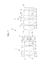
- FIG. 7 shows the normal observation state, in which the second lens group 2 has been moved toward the object.
- Fig. 8 shows the magnifying observation state, in which the second lens group 2 has been moved toward the image.
- Figs. 9 and 10 show spherical aberration, astigmatism, chromatic aberration of magnification, and distortion, corresponding to Figs. 7 and 8 , respectively.
- the endoscope objective lens 10 according to this example has the data shown in Tables 4, 5, and 6.
- FIG. 11 shows the normal observation state, in which the second lens group 2 has been moved toward the object.
- Fig. 12 shows the magnifying observation state, in which the second lens group 2 has been moved toward the image.
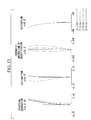
- Figs. 13 and 14 show spherical aberration, astigmatism, chromatic aberration of magnification, and distortion, corresponding to Figs. 11 and 12 , respectively.
- the endoscope objective lens 10 according to this example has the data shown in Tables 7, 8, and 9.
- FIG. 15 shows the normal observation state, in which the second lens group 2 has been moved toward the object.
- Fig. 16 shows the magnifying observation state, in which the second lens group 2 has been moved toward the image.
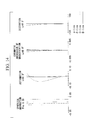
- Figs. 17 and 18 show spherical aberration, astigmatism, chromatic aberration of magnification, and distortion, corresponding to Figs. 15 and 16 , respectively.
- the endoscope objective lens 10 according to this example has the data shown in Tables 10, 11, and 12.
- FIG. 19 shows the normal observation state, in which the second lens group 2 has been moved toward the object.
- Fig. 20 shows the magnifying observation state, in which the second lens group 2 has been moved toward the image. Furthermore, Figs. 21 and 22 show spherical aberration, astigmatism, chromatic aberration of magnification, and distortion, corresponding to Figs. 19 and 20 , respectively. Furthermore, the endoscope objective lens 10 according to this example has the data shown in Tables 13, 14, and 15.
- An illumination optical system may be configured as described below.
- An endoscope scope 50 is configured as shown in Fig. 23 , and an image acquisition optical system 51, illumination optical systems 53A and 53B, and a forceps channel 55 are provided therein. If the two illumination optical systems 53A and 53B are provided, as in the example shown in Fig. 23 , when forceps 57 come out from the forceps channel 55, two shadows of the forceps 57 are cast, as shown in Fig. 24 . At this time, if there is a difference between the levels of light emitted from the illumination optical systems 53A and 53B, one of the shadows is darker, which may make it difficult to view a lesion.
- the ratio between the numbers of light guide members of these two illumination optical systems or the area ratio between tip lenses of the two illumination optical systems 53A and 53B becomes 2 or higher, the difference in darkness between the shadows makes the viewing difficulty more prominent. If this ratio is 2.6 or higher, viewing the lesion becomes very difficult.
- the illumination optical systems 53A and 53B should be configured as described below.
- an antireflection coating should not be applied to at least two surfaces in the illumination optical system that has a higher level of light, of the illumination optical systems 53A and 53B.
- an antireflection coating is not applied to two surfaces in the illumination optical system 53B shown in Fig. 25 . With this configuration, the level of light from the illumination optical system 53B, which has a higher level of light, is reduced, thus reducing the difference in darkness between the shadows of the forceps 57.
- an antireflection coating should be applied to all surfaces in the illumination optical system that has a lower level of light.
- an antireflection coating is applied to all surfaces in the illumination optical system 53A shown in Fig. 26 .
- the illumination optical systems and the forceps channel 55 should be positioned as described below. Specifically, as shown in Fig. 27 , when the angle between a straight line connecting the center of the image acquisition optical system 51 and the center of the forceps channel 55 and a straight line connecting the center of the illumination optical system 53B, which has a higher level of light, and the center of the forceps channel 55 is ⁇ , should be 60° or smaller.
- the lens tolerance may be set as described below.
- the angle of view and the angular deviation are adjusted for assembly, in some cases.
- the angle of view is adjusted by changing the gap between some lenses.
- the endoscope is a general wide-angle optical system, its basic configuration is a retrofocus type having a concave lens and a convex lens, in this order from the object side.
- the lens tolerance for adjusting the angle of view should be set as described below.
- At least two lenses i.e., an adjustment lens and a fixed lens, in this order from the object side, be provided, that the angle of view be adjusted by adjusting the gap therebetween, and that the eccentricity tolerance for the adjustment lens be set smaller than the eccentricity tolerance for the fixed lens.
- the eccentricity tolerance is an acceptable value for an amount of shift between an axis with respect to the outer diameter of the lens and the lens optical axis.
- the adjustment lens should be a concave lens, and the fixed lens should be a convex lens.
- ⁇ n represents the eccentricity tolerance for the adjustment lens
- ⁇ p represents the eccentricity tolerance for the fixed lens
- ⁇ n/ ⁇ p exceeds the upper limit of the conditional expression, the tolerance for the adjustment lens is too relaxed, thus causing an angular deviation, or the tolerance for the fixed lens is too strict, thus causing an increase in cost.
- the value of ⁇ n/ ⁇ p falls below the lower limit thereof, the tolerance for the adjustment lens is too strict, thus making it impossible to move the lens for adjustment, or the tolerance for the fixed lens is too relaxed, thus making it impossible to completely adjust the angular deviation.
- fn the focal distance of the adjustment lens
- fp the focal distance of the fixed lens
Landscapes
- Physics & Mathematics (AREA)
- Health & Medical Sciences (AREA)
- Life Sciences & Earth Sciences (AREA)
- Optics & Photonics (AREA)
- Surgery (AREA)
- General Physics & Mathematics (AREA)
- Biomedical Technology (AREA)
- General Health & Medical Sciences (AREA)
- Pathology (AREA)
- Engineering & Computer Science (AREA)
- Nuclear Medicine, Radiotherapy & Molecular Imaging (AREA)
- Heart & Thoracic Surgery (AREA)
- Medical Informatics (AREA)
- Molecular Biology (AREA)
- Animal Behavior & Ethology (AREA)
- Radiology & Medical Imaging (AREA)
- Public Health (AREA)
- Veterinary Medicine (AREA)
- Astronomy & Astrophysics (AREA)
- Biophysics (AREA)
- Lenses (AREA)
- Endoscopes (AREA)
- Instruments For Viewing The Inside Of Hollow Bodies (AREA)
Description
- The present invention relates to an endoscope objective lens, in particular, to an endoscope variable-magnification objective lens that is used for an endoscope capable of performing magnifying observation in addition to normal observation.
- In recent years, endoscopes (objective lenses) capable of performing magnifying observation have been in high demand in the medical field in order to make accurate diagnoses of lesions. Magnifying observation with an endoscope is performed such that some lenses in the objective lens are moved to change the focal distance, thus changing the observation distance. For example, when the endoscope is focused at a distance of about 5 mm for normal observation, the lenses are moved to change the focal distance, thereby making it possible to focus the endoscope at a distance of up to about 2 mm. As a result, by changing the focal distance from 5 mm to 2 mm, an object can be observed in magnified form, thus allowing magnifying observation. This configuration of lenses is generally called a focusing lens, which is different from zoom lenses that are used in cameras.
- As such endoscope objective lenses capable of performing magnifying observation, endoscope optical systems that have a configuration formed of three lens groups, namely, positive, negative, and positive lens groups, and that move the second lens group, thereby performing variable magnification and focusing, are disclosed in
PTLs 1 and 2. -
- {PTL 1} Publication of Japanese Patent No.
4659645 - {PTL 2} Japanese Unexamined Patent Application, Publication No.
2012-32576 - However, the endoscope optical systems disclosed in
PTLs 1 and 2 had the following problems. That is to say, in both of the endoscope optical systems disclosed inPTLs 1 and 2, magnifying observation is allowed by moving the second lens group; however, the power of the second lens group is high, and a change in magnification with respect to the lens movement distance is large. Therefore, the position adjustment of the second lens group becomes difficult. More specifically, manufacturing errors tend to occur whereby, for magnifying observation, although the magnification can be ensured, the depth of field is narrowed; or although the depth of field can be ensured, the magnification does not reach a desired level. - An object of the present invention is to provide an endoscope objective lens for which manufacturing errors are suppressed, that is provided with a variable magnification function, and that can perform good observation with aberrations appropriately corrected.
- In order to achieve the above-described object, the present invention provides the following solutions.
- According to one aspect, the present invention provides an endoscope objective lens including, in order from an object side, a positive first lens group, a negative second lens group, and a positive third lens group, in which the first lens group has a meniscus lens; and a normal observation state (wide angle end) and a magnifying observation state (telephoto end) can be switched between by moving the second lens group on an optical axis, and the following conditions are satisfied;


- Expression (1) relates to the position adjustment sensitivity of the second lens group. If the value of f2/fw falls below the lower limit of Expression (1), manufacturing errors are increased. If the position adjustment sensitivity is high, the deviation from the designed objective lens is greater, thus causing a problem in that, although the magnification can be ensured, the depth of field is narrowed or a problem in that, although the depth of field can be ensured, the magnification does not reach a desired level, for example. On the other hand, if the value of f2/fw exceeds the upper limit of Expression (1), the position adjustment sensitivity is relaxed, but it becomes difficult to ensure sufficient magnification.
- The following expression is more preferable than Expression (1).

- Expression (2) relates to successful correction of the aberrations, in particular, chromatic aberration of magnification. If the value of |fM/fW| falls below the lower limit of Expression (2), the lens focal distance is reduced, which leads to excessive correction of the chromatic aberration of magnification, as a result. On the other hand, if the value of |fM/fW| exceeds the upper limit of Expression (2), the focal distance is increased, which leads to insufficient correction.
- The following expression is more preferable than Expression (2).

- In the above-described aspect, the second lens group may consist of a joined lens that is formed of a concave lens having a high refractive index and a convex lens having a low refractive index; and a lens surface of the second lens group that is located closest to an object and a lens surface thereof that is located closest to an image may each have a planar shape.
- The second lens group may be provided, for example, with a movement mechanism such as an actuator to be connected to a lens frame for holding a movable lens group to give a driving force to the lens frame. In such a case, aside from eccentricity and tilt caused by a clearance between the lenses and the lens frame, eccentricity and tilt are caused by a clearance between the movement mechanism and the lens frame. Therefore, the levels of eccentricity and tilt caused in the lenses of the second lens group are increased compared with those caused in the lenses of the first lens group and in the lenses of the third lens group, to which a movement mechanism is not connected.
- When eccentricity and tilt are increased, aberrations become worse, thus degrading the performance; therefore, it is desirable to provide a configuration for reducing the effects of eccentricity and tilt caused by the lenses and the lens frame. Thus, the second lens group is made to consist of the joined lens, which is formed of the concave lens having a high refractive index and the convex lens having a low refractive index, thereby forming it into a parallel plate shape as a whole; therefore, it is possible to hamper the occurrence of eccentricity and tilt and to exert a negative refractive index as power.
- In order to reduce the load imposed on the movement mechanism, it is desirable that the second lens group have a small lens diameter. With a small diameter, processing for a meniscus lens is difficult, and the cost tends to be increased, as a result. From this point of view, it is desirable to provide the configuration of the present invention.
- In the above-described aspect, an aperture stop that is moved together with the second lens group may be further included.
- For the normal observation and the magnifying observation, it is difficult to ensure the depth of field especially when a CCD having a large number of pixels is used. Therefore, in many cases, the f-number is increased as much as possible to narrow the aperture stop close to the diffraction limit, thereby ensuring the depth of field. However, in an optical system in which a lens group is moved, especially in an optical system having a positive-negative-positive configuration, the f-number for the normal observation becomes small, thus making it difficult to ensure a sufficient depth of field. Therefore, by moving the aperture stop and the lens at the same time, it is possible to reduce a change in f-number between the normal observation and the magnifying observation.
- In the above-described aspect, the following conditional expression may be satisfied;

- If the value of f3/f2 falls below the lower limit of Expression (3), the focal distance of the third lens group is increased, which increases the backfocus of the optical system. As a result, the overall length of the optical system is increased, which causes an increase in size. On the other hand, if the value of f3/f2 exceeds the upper limit of Expression (3), the aberrations in the third lens group, in particular, chromatic aberration of magnification, cannot be sufficiently corrected, which causes image degradation due to color blurring. Therefore, it is desirable to satisfy Expression (3).
- The following expression is more preferable than Expression (3).

- In the above-described aspect, the following conditional expression may be satisfied;

- If the value of f2/f1 falls below the lower limit of Expression (4), the focal distance of the first lens group is reduced, and increased spherical aberration occurs, thus making it difficult to acquire an excellent image. On the other hand, if the value of f2/f1 exceeds the upper limit of Expression (4), the focal distance of the first lens group is increased, and the outer diameter of the lens in the first lens group, in particular, the first lens closest to the object, is increased, thus increasing the tip diameter of the endoscope. Therefore, it is desirable to satisfy Expression (4).
- The following expression is more preferable than Expression (4).

- In the above-described aspect, the following conditional expression may be satisfied;

- If the value of f3/f1 falls below the lower limit of Expression (5), as in Expression (4), the focal distance of the first lens group is increased, thus making it difficult to correct the spherical aberration. Furthermore, the comatic aberration cannot be corrected. On the other hand, if the value of f3/f1 exceeds the upper limit of Expression (5), the focal distance of the third lens group is increased, thus making it difficult to correct the field curvature. If a large field curvature is caused, the resolving power is different between the center of an image and an edge thereof, thus making it difficult to acquire an excellent image. Therefore, it is desirable to satisfy Expression (5).
- The following expression is more preferable than Expression (5).

- {Brief Description of Drawings}
- The present invention affords an advantage in that good observation with aberrations appropriately corrected can be performed.
-
- {
Fig. 1} Fig. 1 is a view showing, in outline, the configuration of a normal observation state of an endoscope objective lens according to one embodiment of the present invention. - {
Fig. 2} Fig. 2 is a view showing, in outline, the configuration of a magnifying observation state of the endoscope objective lens according to the embodiment of the present invention. - {
Fig. 3} Fig. 3 is a view showing the normal observation state of an endoscope objective lens according to Example 1 of the embodiment of the present invention. - {
Fig. 4} Fig. 4 is a view showing the magnifying observation state of the endoscope objective lens according to Example 1 of the embodiment of the present invention. - {
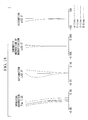
Fig. 5} Fig. 5 shows aberration diagrams for the endoscope objective lens in the normal observation state shown inFig. 3 . - {
Fig. 6} Fig. 6 shows aberration diagrams for the endoscope objective lens in the magnifying observation state shown inFig. 4 . - {
Fig. 7} Fig. 7 is a view showing the normal observation state of an endoscope objective lens according to Example 2 of the embodiment of the present invention. - {
Fig. 8} Fig. 8 is a view showing the magnifying observation state of the endoscope objective lens according to Example 2 of the embodiment of the present invention. - {
Fig. 9} Fig. 9 shows aberration diagrams for the endoscope objective lens in the normal observation state shown inFig. 7 . - {
Fig. 10} Fig. 10 shows aberration diagrams for the endoscope objective lens in the magnifying observation state shown inFig. 8 . - {
Fig. 11} Fig. 11 is a view showing the normal observation state of an endoscope objective lens according to Example 3 of the embodiment of the present invention. - {
Fig. 12} Fig. 12 is a view showing the magnifying observation state of the endoscope objective lens according to Example 3 of the embodiment of the present invention. - {
Fig. 13} Fig. 13 shows aberration diagrams for the endoscope objective lens in the normal observation state shown inFig. 11 . - {
Fig. 14} Fig. 14 shows aberration diagrams for the endoscope objective lens in the magnifying observation state shown inFig. 12 . - {
Fig. 15} Fig. 15 is a view showing the normal observation state of an endoscope objective lens according to Example 4 of the embodiment of the present invention. - {
Fig. 16} Fig. 16 is a view showing the magnifying observation state of the endoscope objective lens according to Example 2 of the embodiment of the present invention. - {
Fig. 17} Fig. 17 shows aberration diagrams for the endoscope objective lens in the normal observation state shown inFig. 15 . - {
Fig. 18} Fig. 18 shows aberration diagrams for the endoscope objective lens in the magnifying observation state shown inFig. 16 . - {
Fig. 19} Fig. 19 is a view showing the normal observation state of an endoscope objective lens according to Example 5 of the embodiment of the present invention. - {
Fig. 20} Fig. 20 is a view showing the magnifying observation state of the endoscope objective lens according to Example 2 of the embodiment of the present invention. - {
Fig. 21} Fig. 21 shows aberration diagrams for the endoscope objective lens in the normal observation state shown inFig. 19 . - {
Fig. 22} Fig. 22 shows aberration diagrams for the endoscope objective lens in the magnifying observation state shown inFig. 20 . - {
Fig. 23} Fig. 23 is a sectional view of an endoscope scope. - {
Fig. 24} Fig. 24 is a view showing example shadows of forceps. - {
Fig. 25} Fig. 25 is a view showing an example in which an antireflection coating is applied partially to two illumination optical systems. - {
Fig. 26} Fig. 26 is a view showing another example in which an antireflection coating is applied partially to the two illumination optical systems. - {
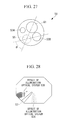
Fig. 27} Fig. 27 is a view showing an example positional relationship between the illumination optical systems and a forceps channel. - {
Fig. 28} Fig. 28 is a view showing example shadows of the forceps cast by the endoscope scope shown inFig. 27 . - An endoscope objective lens according to one embodiment of the present invention will be described below with reference to the drawings.
- As shown in
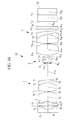
Figs. 1 and2 , anendoscope objective lens 10 of this embodiment includes, in order from the object side, a positive first lens group 1, anaperture stop 4, a negativesecond lens group 2, and a positivethird lens group 3. - The first lens group 1 consists of, in order from the object side, a
planoconcave lens 11 whose flat surface faces the object side, aparallel plate 12, ameniscus lens 13 whose concave surface faces the object side, and a joinedlens 16 that is formed of abiconvex lens 14 and aconcave lens 15. - The
second lens group 2 consists of a joinedlens 23 that is formed of aconcave lens 21 having a high refractive index and aconvex lens 22 having a low refractive index. A lens surface (r10 shown inFig. 3 ) of thesecond lens group 2 that is located closest to an object and a lens surface (r12 shown inFig. 3 ) thereof that is located closest to an image each have a planar shape. - The
third lens group 3 consists of aplanoconvex lens 31 whose flat surface faces the object side; a joinedlens 34 that is formed of abiconvex lens 32 and aconcave lens 33; and threeparallel plates - The
second lens group 2 of this embodiment is provided so as to be capable of being moved on an optical axis together with theaperture stop 4. For example, the joined lens 23 (movable lens group), which is formed of theconcave lens 21 and theconvex lens 22, is held by a lens frame (not shown), and an actuator (movement mechanism, not shown) for giving a driving force to the lens frame is connected to the lens frame. Then, the joinedlens 23 is moved on the optical axis together with the lens frame through actuation of the actuator. - Aside from eccentricity and tilt caused by a clearance between the lenses and the lens frame, eccentricity and tilt are caused by a clearance between the actuator (movement mechanism) and the lens frame. Therefore, the levels of eccentricity and tilt caused in the lenses of the
second lens group 2, to which the movement mechanism is connected, are increased compared with those caused in the lenses of the first lens group 1 and in the lenses of thethird lens group 3, to which a movement mechanism is not connected. - When eccentricity and tilt are increased, aberrations become worse, thus degrading the performance; therefore, it is desirable to provide a configuration for reducing the effects of eccentricity and tilt caused by the lenses and the lens frame. Thus, the
second lens group 2 is made to consist of the joinedlens 23, which is formed of theconcave lens 21 having a high refractive index and theconvex lens 22 having a low refractive index, thereby forming it into a parallel plate shape as a whole; therefore, it is possible to hamper the occurrence of eccentricity and tilt and to exert a negative refractive index as power. - In order to reduce the load imposed on the movement mechanism, it is desirable that the
second lens group 2 have a small lens diameter. With a small diameter, processing for a meniscus lens is difficult, and the cost tends to be increased, as a result. Therefore, it is desirable to provide the configuration of thesecond lens group 2 of this embodiment. - The
endoscope objective lens 10 can be switched between a normal observation state (wide angle end) and a magnifying observation state (telephoto end) by moving thesecond lens group 2 on the optical axis in the axial direction. For example, theendoscope objective lens 10 enters the normal observation state when thesecond lens group 2 is moved on the optical axis toward the object, as shown inFig. 1 , and enters the magnifying observation state when thesecond lens group 2 is moved on the optical axis toward the image, as shown inFig. 2 . - For the normal observation and the magnifying observation, it is difficult to ensure the depth of field especially when a CCD having a large number of pixels is used. Therefore, in many cases, the f-number is increased as much as possible to narrow the
aperture stop 4 close to the diffraction limit, thereby ensuring the depth of field. However, in an optical system in which a lens group is moved, especially in an optical system having a positive-negative-positive configuration, the f-number for the normal observation becomes small, thus making it difficult to ensure a sufficient depth of field. Therefore, by moving theaperture stop 4 and thesecond lens group 2 at the same time, it is possible to reduce a change in f-number between the normal observation and the magnifying observation. - In this embodiment, the
endoscope objective lens 10 satisfies the following conditional expressions;

meniscus lens 13, fw represents the entire focal distance for the normal observation, and f2 represents the focal distance of thesecond lens group 2. - Expression (1) relates to the position adjustment sensitivity of the
second lens group 2. If the value of f2/fw falls below the lower limit of Expression (1), manufacturing errors are increased. If the position adjustment sensitivity is high, the deviation from the designed objective lens is greater, thus causing a problem in that, although the magnification can be ensured, the depth of field is narrowed or a problem in that, although the depth of field can be ensured, the magnification does not reach a desired level, for example. On the other hand, if the value of f2/fw exceeds the upper limit of Expression (1), the position adjustment sensitivity is relaxed, but it becomes difficult to ensure sufficient magnification. - The following expression is more preferable than Expression (1).

- Expression (2) relates to successful correction of the aberrations, in particular, chromatic aberration of magnification. If the value of |fM/fW| falls below the lower limit of Expression (2), the lens focal distance is reduced, which leads to excessive correction of the chromatic aberration of magnification, as a result. On the other hand, if the value of |fM/fW| exceeds the upper limit of Expression (2), the focal distance is increased, which leads to insufficient correction.
- The following expression is more preferable than Expression (2).

- Furthermore, the
endoscope objective lens 10 satisfies the following conditional expression;
third lens group 3. - If the value of f3/f2 falls below the lower limit of Expression (3), the focal distance of the
third lens group 3 is increased, which increases the backfocus of the optical system. As a result, the overall length of the optical system is increased, which causes an increase in size. On the other hand, if the value of f3/f2 exceeds the upper limit of Expression (3), the aberrations in thethird lens group 3, in particular, chromatic aberration of magnification, cannot be sufficiently corrected, which causes image degradation due to color blurring. Therefore, it is desirable to satisfy Expression (3). - The following expression is more preferable than Expression (3).

- Furthermore, the
endoscope objective lens 10 satisfies the following conditional expression;
- If the value of f2/f1 falls below the lower limit of Expression (4), the focal distance of the first lens group 1 is reduced, and increased spherical aberration occurs, thus making it difficult to acquire an excellent image. On the other hand, if the value of f2/f1 exceeds the upper limit of Expression (4), the focal distance of the first lens group 1 is increased, and the outer diameter of the lens in the first lens group 1, in particular, the
first lens 11 closest to the object, is increased, thus increasing the tip diameter of the endoscope. Therefore, it is desirable to satisfy Expression (4). - The following expression is more preferable than Expression (4).

- Furthermore, the
endoscope objective lens 10 satisfies the following conditional expression.
- If the value of f3/f1 falls below the lower limit of Expression (5), as in Expression (4), the focal distance of the first lens group 1 is increased, thus making it difficult to correct the spherical aberration. Furthermore, the comatic aberration cannot be corrected. On the other hand, if the value of f3/f1 exceeds the upper limit of Expression (5), the focal distance of the
third lens group 3 is increased, thus making it difficult to correct the field curvature. If a large field curvature is caused, the resolving power is different between the center of an image and an edge thereof, thus making it difficult to acquire an excellent image. Therefore, it is desirable to satisfy Expression (5). - The following expression is more preferable than Expression (5).

- Next, examples of the
endoscope objective lens 10 of the embodiment of the present invention will be described below with reference to the drawings. - An
endoscope objective lens 10 according to Example 1 of the present invention is shown inFigs. 3 and4 .Fig. 3 shows a state in which thesecond lens group 2 has been moved toward the object, that is, a normal observation state.Fig. 4 shows a state in which thesecond lens group 2 has been moved toward the image, that is, a magnifying observation state. - In
Figs. 3 and4 , r1 to r9 denote surfaces of the lenses constituting the positive first lens group 1, r10 to r12 denote surfaces of the lenses constituting the negativesecond lens group 2, and r13 to r22 denote surfaces of the lenses constituting the positivethird lens group 3. The same applies toFigs. 7 ,8 ,11 ,12 ,15 ,16 ,19 , and20 . Furthermore,Figs. 5 and6 show spherical aberration, astigmatism, chromatic aberration of magnification, and distortion, corresponding toFigs. 3 and4 , respectively. Furthermore, theendoscope objective lens 10 according to this example has the data shown in Tables 1, 2, and 3.(Table 1) object surface d0 D0 r1 ∞ d1 0.35 n1 1.88300 ν 1 40.76 r2 1.056 d2 0.70 r3 ∞ d3 0.40 n2 1.52100 ν 2 65.13 r4 ∞ d4 0.61 r5 -1.967 d5 1.0 n3 1.58913 ν 3 61.14 r6 -1.619 d6 0.05 r7 4.511 d7 1.30 n4 1.80100 ν 4 34.97 r8 -2.191 d8 0.37 n5 1.92286 ν 5 18.9 r9 -7.467 d9 D9 r10 ∞ d10 0.03 r11 ∞ d11 0.30 n6 1.77250 ν 6 49.6 r12 1.240 d12 0.42 n7 1.59270 ν 7 35.31 r13 ∞ d13 D13 r14 ∞ d14 1.43 n8 1.48749 ν 8 70.23 r15 -2.297 d15 0.05 r16 4.815 d16 1.54 n9 1.48749 ν 9 70.23 r17 -2.159 d17 0.45 n10 1.92286 ν 10 18.9 r18 -6.198 d18 0.33 r19 ∞ d19 0.40 n11 1.52300 ν 11 58.5 r20 ∞ d20 0.68 r21 ∞ d21 0.75 n12 1.51633 ν 12 64.14 r22 ∞ d22 0.65 n13 1.50510 ν 13 63.26 (Table 2) normal observation state magnifying observation state D0 14.5 2 D9 0.2 1.8 D13 1.9 0.3 f1 1.25 1.46 Fno 7.59 7.49 (Table 3) Conditional Expressions (1) ∼ (5) f2/fW -5.53 |fM/fW| 5.94 f3/f2 -0.54 f2/f1 -3.25 f3/f1 1.74 - In the above-described data, data items corresponding to r1 to r22 are the radii of curvature of the surfaces of the lenses, data items corresponding to d1 to d22 are the thicknesses and intersurface distances of the lenses, data items corresponding to n1 to n13 are the refractive indexes of the lenses with respect to the d line, and data items corresponding to ν1 to ν13 are the Abbe numbers of the lenses with respect to the d line. Therefore, d0 is the distance from the object surface to a first surface (r1) of the objective lens. The unit of length represented by r and d is mm.
- In this example, because the
endoscope objective lens 10 satisfies Conditional Expressions (1) to (5), manufacturing errors are suppressed, and the aberrations are successfully removed. - An
endoscope objective lens 10 according to Example 2 of the embodiment of the present invention, is shown inFigs. 7 and8 .Fig. 7 shows the normal observation state, in which thesecond lens group 2 has been moved toward the object.Fig. 8 shows the magnifying observation state, in which thesecond lens group 2 has been moved toward the image. Furthermore,Figs. 9 and10 show spherical aberration, astigmatism, chromatic aberration of magnification, and distortion, corresponding toFigs. 7 and8 , respectively. Furthermore, theendoscope objective lens 10 according to this example has the data shown in Tables 4, 5, and 6.(Table 4) object surface d0 D0 r1 ∞ d1 0.35 n1 1.88300 ν 1 40.76 r2 1.051 d2 0.48 r3 ∞ d3 0.40 n2 1.52100 ν 2 65.13 r4 ∞ d4 0.60 r5 -3.073 d5 1.30 n3 1.69680 ν 3 55.53 r6 -3.020 d6 0.05 r7 6.393 d7 1.23 n4 1.77250 ν 4 49.6 r8 -2.178 d8 0.34 n5 1.92286 ν 5 18.9 r9 -3.445 d9 D9 r10 ∞ d10 0.03 r11 ∞ d11 0.30 n6 1.77250 ν 6 49.6 r12 1.542 d12 0.42 n7 1.59270 ν 7 35.31 r13 8.817 d13 D13 r14 3.549 d14 1.23 n8 1.48749 ν 8 70.23 r15 -9.319 d15 0.05 r16 2.879 d16 1.61 n9 1.48749 ν 9 70.23 r17 -2.799 d17 0.33 n10 1.92286 ν 10 18.9 r18 -15.968 d18 0.33 r19 ∞ d19 0.40 n11 1.52300 ν 11 58.5 r20 ∞ d20 0.81 r21 ∞ d21 0.75 n12 1.51633 ν 12 64.14 r22 ∞ d22 0.65 n13 1.50510 ν 13 63.26 (Table 5) normal observation state magnifying observation state D0 12 2 D9 0.2 1.8 D13 1.9 0.3 f1 1.19 1.44 Fno 7.41 7.98 (Table 6) Conditional Expressions (1) ∼ (5) f2/fW -4.51 |fM/fW| 19.0 f3/f2 -0.67 f2/f1 -2.53 f3/f1 1.69 - In this example, because the
endoscope objective lens 10 satisfies Conditional Expressions (1) to (5), manufacturing errors are suppressed, and the aberrations are successfully removed. - An
endoscope objective lens 10 according to Example 2 of the present invention is shown inFigs. 11 and12 .Fig. 11 shows the normal observation state, in which thesecond lens group 2 has been moved toward the object.Fig. 12 shows the magnifying observation state, in which thesecond lens group 2 has been moved toward the image. Furthermore,Figs. 13 and14 show spherical aberration, astigmatism, chromatic aberration of magnification, and distortion, corresponding toFigs. 11 and12 , respectively. Furthermore, theendoscope objective lens 10 according to this example has the data shown in Tables 7, 8, and 9.(Table 7) object surface d0 D0 r1 ∞ d1 0.35 n1 1.88300 ν 1 40.76 r2 1.052 d2 0.71 r3 ∞ d3 0.40 n2 1.52100 ν 2 65.13 r4 ∞ d4 0.50 r5 -9.095 d5 1.20 n3 1.69680 ν 3 55.53 r6 -4.411 d6 0.05 r7 10.770 d7 1.00 n4 1.77250 ν 4 49.6 r8 -1.970 d8 0.34 n5 1.92286 ν 5 18.9 r9 -3.048 d9 D9 r10 ∞ d10 0.03 r11 ∞ d11 0.30 n6 1.77250 ν 6 49.6 r12 1.389 d12 0.42 n7 1.59270 ν 7 35.31 r13 ∞ d13 D13 r14 3.517 d14 1.00 n8 1.48749 ν 8 70.23 r15 -63.204 d15 0.05 r16 2.611 d16 1.63 n9 1.48749 ν 9 70.23 r17 -3.191 d17 0.33 n10 1.92286 ν 10 18.9 r18 ∞ d18 0.33 r19 ∞ d19 0.40 n11 1.52300 ν 11 58.5 r20 ∞ d20 0.70 r21 ∞ d21 0.75 n12 1.51633 ν 12 64.14 r22 ∞ d22 0.65 n13 1.50510 ν 13 63.26 (Table 8) normal observation state magnifying observation state D0 12 2 D9 0.2 2.2 D13 2.3 0.3 f1 1.34 1.52 Fno 8.06 8.09 (Table 9) Conditional Expressions (1) ∼ (5) f2/fW -5.78 |fM/fW| 8.3 f3/f2 -0.54 f2/f1 -3.24 f3/f1 1.77 - In this example, because the
endoscope objective lens 10 satisfies Conditional Expressions (1) to (5), manufacturing errors are suppressed, and the aberrations are successfully removed. - An
endoscope objective lens 10 according to Example 4 of the embodiment of the present invention, is shown inFigs. 15 and16 .Fig. 15 shows the normal observation state, in which thesecond lens group 2 has been moved toward the object.Fig. 16 shows the magnifying observation state, in which thesecond lens group 2 has been moved toward the image. Furthermore,Figs. 17 and18 show spherical aberration, astigmatism, chromatic aberration of magnification, and distortion, corresponding toFigs. 15 and16 , respectively. Furthermore, theendoscope objective lens 10 according to this example has the data shown in Tables 10, 11, and 12.(Table 10) object surface d0 D0 r1 ∞ d1 0.32 n1 1.88300 ν 1 40.76 r2 0.747 d2 0.37 r3 ∞ d3 0.30 n2 1.52100 ν 2 65.13 r4 ∞ d4 0.20 r5 -1.107 d5 1.01 n3 .69895 ν 3 30.13 r6 -1.681 d6 0.03 r 5.058 d7 0.94 n4 1.77250 ν 4 49.6 r8 -1.572 d8 0.32 n5 1.92286 ν 5 18.9 r9 -2.576 d9 D9 r10 ∞ d10 0.03 r11 ∞ d11 0.30 n6 1.77250 ν 6 49.6 r12 1.409 d12 0.32 n7 1.59270 ν 7 35.31 r13 ∞ d13 D13 r14 3.089 d14 1.20 n8 1.48749 ν 8 70.23 r15 -3.001 d15 0.05 r16 10.794 d16 0.94 n9 1.48749 ν 9 70.23 r17 -1.670 d17 0.34 n10 1.92286 ν 10 18.9 r18 -4.015 d18 0.25 r19 ∞ d19 0.30 n11 1.52100 ν 11 65.13 r20 ∞ d20 0.53 r21 ∞ d21 0.70 n12 1.51633 ν 12 64.14 r22 ∞ d22 0.70 n13 1.50510 ν 13 63.26 (Table 11) normal observation state magnifying observation state D0 7.5 1.6 D9 0.2 1.8. D13 1.8 0.2 f1 0.89 1.03 Fno 7.43 7.35 (Table 12) Conditional Expressions (1) ∼ (5) f2/fW -8.79 |fM/fW| 19.0 f3/f2 -0.41 f2/f1 -4.03 f3/f1 1.65 - In this example, because the
endoscope objective lens 10 satisfies Conditional Expressions (1) to (5), manufacturing errors are suppressed, and the aberrations are successfully removed. - An
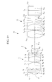
endoscope objective lens 10 according to Example 5 of the embodiment of the present invention, is shown inFigs. 19 and20 .Fig. 19 shows the normal observation state, in which thesecond lens group 2 has been moved toward the object. -
Fig. 20 shows the magnifying observation state, in which thesecond lens group 2 has been moved toward the image. Furthermore,Figs. 21 and22 show spherical aberration, astigmatism, chromatic aberration of magnification, and distortion, corresponding toFigs. 19 and20 , respectively. Furthermore, theendoscope objective lens 10 according to this example has the data shown in Tables 13, 14, and 15.(Table 13) object surface d0 D0 r1 ∞ d1 0.32 n1 1.88300 ν 1 40.76 r2 0.820 d2 0.37 r3 ∞ d3 0.30 n2 1.52100 ν 2 65.13 r4 ∞ d4 0.20 r5 -1.072 d5 1.01 n3 1.69895 ν 3 30.13 r6 -1.575 d6 0.03 r7 3.911 d7 0.86 n4 1.77250 ν 4 49.6 r8 -1.695 d8 0.32 n5 1.92286 ν 5 18.9 r9 -3.020 d9 D9 r10 ∞ d10 0.03 r11 ∞ d11 0.30 n6 1.77250 ν 6 49.6 r12 1.301 d12 0.32 n7 1.59270 ν 7 35.31 r13 ∞ d13 D13 r14 3.887 d14 1.20 n8 1.48749 ν 8 70.23 r15 -2.731 d15 0.05 r16 7.273 d16 0.91 n9 1.48749 ν 9 70.23 r17 -1.748 d17 0.34 n10 1.92286 ν 10 18.9 r18 -4.176 d18 0.25 r19 ∞ d19 0.30 n11 1.52100 ν 11 65.13 r20 ∞ d20 0.53 r21 ∞ d21 0.70 n12 1.51633 ν 12 64.14 r22 ∞ d22 0.70 n13 1.50510 ν 13 63.26 (Table 14) normal observation state magnifying observation state D0 7.5 1.6 D9 0.2 1.8 D13 1.8 0.2 f1 0.97 1.14 Fno 7.42 7.47 (Table 15) Conditional Expressions (1) ∼ (5) f2/fW -7.47 |fM/fW| 28.4 f3/f2 -0.43 f2/f1 -3.75 f3/f1 1.63 - In this example, because the
endoscope objective lens 10 satisfies Conditional Expressions (1) to (5), manufacturing errors are suppressed, and the aberrations are successfully removed. - An illumination optical system may be configured as described below.
- An
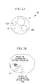
endoscope scope 50 is configured as shown inFig. 23 , and an image acquisitionoptical system 51, illuminationoptical systems forceps channel 55 are provided therein. If the two illuminationoptical systems Fig. 23 , whenforceps 57 come out from theforceps channel 55, two shadows of theforceps 57 are cast, as shown inFig. 24 . At this time, if there is a difference between the levels of light emitted from the illuminationoptical systems optical systems - At this time, the illumination
optical systems - It is preferred that an antireflection coating should not be applied to at least two surfaces in the illumination optical system that has a higher level of light, of the illumination
optical systems optical system 53B shown inFig. 25 . With this configuration, the level of light from the illuminationoptical system 53B, which has a higher level of light, is reduced, thus reducing the difference in darkness between the shadows of theforceps 57. - At this time, furthermore, it is more preferred that an antireflection coating should be applied to all surfaces in the illumination optical system that has a lower level of light. For example, an antireflection coating is applied to all surfaces in the illumination
optical system 53A shown inFig. 26 . With this configuration, the level of light from the illuminationoptical system 53A, which has a lower level of light, is increased, thus further reducing the difference in darkness between the shadows of theforceps 57. - Furthermore, the illumination optical systems and the
forceps channel 55 should be positioned as described below. Specifically, as shown inFig. 27 , when the angle between a straight line connecting the center of the image acquisitionoptical system 51 and the center of theforceps channel 55 and a straight line connecting the center of the illuminationoptical system 53B, which has a higher level of light, and the center of theforceps channel 55 is θ, should be 60° or smaller. - With this configuration, as shown in
Fig. 28 , the positions of the shadows of theforceps 57 cast by the illuminationoptical systems forceps 57 themselves, thereby making it easy to observe the lesion. - With this configuration, it is possible to allow endoscopic observation that is less affected by the shadows of the
forceps 57. - Furthermore, the lens tolerance may be set as described below.
- Because lens manufacturing variations cause variations in the angle of view and the angular deviation, the angle of view and the angular deviation are adjusted for assembly, in some cases. In particular, the angle of view is adjusted by changing the gap between some lenses. Since the endoscope is a general wide-angle optical system, its basic configuration is a retrofocus type having a concave lens and a convex lens, in this order from the object side.
- Therefore, the lens tolerance for adjusting the angle of view should be set as described below.
- It is preferred that at least two lenses, i.e., an adjustment lens and a fixed lens, in this order from the object side, be provided, that the angle of view be adjusted by adjusting the gap therebetween, and that the eccentricity tolerance for the adjustment lens be set smaller than the eccentricity tolerance for the fixed lens.
- The eccentricity tolerance is an acceptable value for an amount of shift between an axis with respect to the outer diameter of the lens and the lens optical axis.
- Because the adjustment lens needs to be moved, a variation in shift eccentricity occurring at this time causes angular deviation. Therefore, it is desirable to reduce the eccentricity tolerance for shift. On the other hand, if the lens tolerance is set strictly, the cost is increased. Therefore, relaxing the lens tolerance for the fixed lens is desirable.
- The adjustment lens should be a concave lens, and the fixed lens should be a convex lens.
- Furthermore, it is effective to use those lenses for a wide-angle optical system whose half angle of view is about 80°.
- Furthermore, it is desirable to satisfy the following conditional expression.

- In the conditional expression, δn represents the eccentricity tolerance for the adjustment lens, and δp represents the eccentricity tolerance for the fixed lens.
- If the value of δn/δp exceeds the upper limit of the conditional expression, the tolerance for the adjustment lens is too relaxed, thus causing an angular deviation, or the tolerance for the fixed lens is too strict, thus causing an increase in cost. On the other hand, if the value of δn/δp falls below the lower limit thereof, the tolerance for the adjustment lens is too strict, thus making it impossible to move the lens for adjustment, or the tolerance for the fixed lens is too relaxed, thus making it impossible to completely adjust the angular deviation.
- Furthermore, it is desirable to satisfy the following conditional expression.

- In the conditional expression, fn represents the focal distance of the adjustment lens, and fp represents the focal distance of the fixed lens.
- If the value of fn/fp exceeds the upper limit of the conditional expression, because the difference in power between the adjustment lens and the fixed lens is too large, the adjustment sensitivity is too strict, thus resulting in poor workability. If the value of fn/fp falls below the lower limit thereof, because the difference in power therebetween is too small, adjustment cannot be performed within an adjustment range.
- With this configuration, it is possible to configure an imaging optical system in which cost and performance are well-balanced.
-
- 1
- first lens group
- 2
- second lens group
- 3
- third lens group
- 4
- aperture stop
- 10
- endoscope objective lens
- 11
- concave lens
- 12
- convex lens
- 13
- meniscus lens
Claims (6)
- An endoscope objective lens comprising, in order from an object side, a positive first lens group, a negative second lens group, and a positive third lens group,
wherein the first lens group has a meniscus lens; and
a normal observation state (wide angle end) and a magnifying observation state (telephoto end) can be switched between by moving the second lens group on an optical axis, and the following conditions are satisfied;

- An endoscope objective lens according to claim 1, wherein the second lens group consists of a joined lens that is formed of a concave lens having a high refractive index and a convex lens having a low refractive index; and a lens surface of the second lens group that is located closest to an object and a lens surface thereof that is located closest to an image each have a planar shape.
- An endoscope objective lens according to claim 1 or 2, further comprising an aperture stop that is moved together with the second lens group.
- An endoscope objective lens according to claim 3, satisfying the following conditional expression;

- An endoscope objective lens according to claim 3 or 4, satisfying the following conditional expression;

- An endoscope objective lens according to claims 3 to 5, satisfying the following conditional expression;

Applications Claiming Priority (2)
| Application Number | Priority Date | Filing Date | Title |
|---|---|---|---|
| JP2012204391 | 2012-09-18 | ||
| PCT/JP2013/072621 WO2014045800A1 (en) | 2012-09-18 | 2013-08-23 | Endoscope objective lens |
Publications (3)
| Publication Number | Publication Date |
|---|---|
| EP2899580A1 true EP2899580A1 (en) | 2015-07-29 |
| EP2899580A4 EP2899580A4 (en) | 2016-05-18 |
| EP2899580B1 EP2899580B1 (en) | 2018-04-11 |
Family
ID=50341123
Family Applications (1)
| Application Number | Title | Priority Date | Filing Date |
|---|---|---|---|
| EP13839022.4A Active EP2899580B1 (en) | 2012-09-18 | 2013-08-23 | Endoscope objective lens |
Country Status (5)
| Country | Link |
|---|---|
| US (1) | US9097850B2 (en) |
| EP (1) | EP2899580B1 (en) |
| JP (1) | JP5580953B1 (en) |
| CN (1) | CN104169775B (en) |
| WO (1) | WO2014045800A1 (en) |
Families Citing this family (13)
| Publication number | Priority date | Publication date | Assignee | Title |
|---|---|---|---|---|
| CN104254799B (en) * | 2013-03-26 | 2016-08-31 | 奥林巴斯株式会社 | Endoscope optical system |
| EP3000378B1 (en) * | 2013-05-22 | 2017-11-22 | Olympus Corporation | Endoscope |
| EP3168668A4 (en) * | 2014-07-11 | 2018-03-07 | Olympus Corporation | Objective optical system |
| EP3316016A1 (en) * | 2015-06-23 | 2018-05-02 | Olympus Corporation | Optical system of object for endoscope |
| WO2017043351A1 (en) * | 2015-09-07 | 2017-03-16 | Hoya株式会社 | Variable power optical system for endoscope, and endoscope |
| FR3060773A1 (en) * | 2016-12-20 | 2018-06-22 | Thales | OPTICAL ZOOM WITH MOBILE PUPIL |
| JP6899030B2 (en) * | 2018-03-22 | 2021-07-07 | オリンパス株式会社 | Objective optics, imaging devices, endoscopes, and endoscope systems |
| US11415792B2 (en) | 2018-06-27 | 2022-08-16 | Altek Biotechnology Corporation | Wide-angle endoscope lens |
| CN112147752B (en) * | 2019-06-27 | 2022-05-31 | 荣晶生物科技股份有限公司 | Wide-angle endoscope lens |
| TWI707656B (en) * | 2019-06-27 | 2020-10-21 | 榮晶生物科技股份有限公司 | Wide-angle endoscope lens |
| CN112731638B (en) * | 2020-12-31 | 2022-08-16 | 上海澳华内镜股份有限公司 | Endoscope optical system |
| CN115670350B (en) * | 2022-12-29 | 2023-04-18 | 微创优通医疗科技(上海)有限公司 | Imaging objective lens mechanism of endoscope, zoom lens and endoscope |
| CN118830792A (en) * | 2023-04-25 | 2024-10-25 | 常州联影智融医疗科技有限公司 | Objective lens for endoscope and endoscope |
Family Cites Families (9)
| Publication number | Priority date | Publication date | Assignee | Title |
|---|---|---|---|---|
| JP3349766B2 (en) * | 1993-04-30 | 2002-11-25 | オリンパス光学工業株式会社 | Endoscope objective optical system |
| JP4573378B2 (en) | 1999-11-12 | 2010-11-04 | オリンパス株式会社 | Zoom lens |
| JP4659645B2 (en) * | 2006-03-01 | 2011-03-30 | オリンパスメディカルシステムズ株式会社 | Magnifying endoscope optical system |
| JP5371178B2 (en) * | 2006-03-29 | 2013-12-18 | オリンパスメディカルシステムズ株式会社 | Imaging optical system |
| JP4653823B2 (en) | 2008-06-06 | 2011-03-16 | オリンパスメディカルシステムズ株式会社 | Objective optical system |
| JP5148403B2 (en) * | 2008-07-28 | 2013-02-20 | オリンパスメディカルシステムズ株式会社 | Endoscope objective optical system |
| JP4834799B2 (en) * | 2009-05-26 | 2011-12-14 | オリンパスメディカルシステムズ株式会社 | Endoscope objective lens |
| JP2010286614A (en) * | 2009-06-10 | 2010-12-24 | Sony Corp | Zoom lens and imaging apparatus |
| JP5601924B2 (en) | 2010-07-30 | 2014-10-08 | Hoya株式会社 | Endoscope variable magnification optical system and endoscope |
-
2013
- 2013-08-23 CN CN201380012613.0A patent/CN104169775B/en active Active
- 2013-08-23 JP JP2014509013A patent/JP5580953B1/en active Active
- 2013-08-23 WO PCT/JP2013/072621 patent/WO2014045800A1/en not_active Ceased
- 2013-08-23 EP EP13839022.4A patent/EP2899580B1/en active Active
-
2014
- 2014-03-03 US US14/195,180 patent/US9097850B2/en active Active
Also Published As
| Publication number | Publication date |
|---|---|
| EP2899580B1 (en) | 2018-04-11 |
| US9097850B2 (en) | 2015-08-04 |
| JPWO2014045800A1 (en) | 2016-08-18 |
| CN104169775A (en) | 2014-11-26 |
| JP5580953B1 (en) | 2014-08-27 |
| EP2899580A4 (en) | 2016-05-18 |
| US20140233110A1 (en) | 2014-08-21 |
| CN104169775B (en) | 2018-03-16 |
| WO2014045800A1 (en) | 2014-03-27 |
Similar Documents
| Publication | Publication Date | Title |
|---|---|---|
| EP2899580B1 (en) | Endoscope objective lens | |
| EP2477053B1 (en) | Endoscope objective optical system | |
| US10670854B2 (en) | Endoscope objective optical system | |
| US10251537B2 (en) | Magnifying endoscope optical system | |
| EP2437094A1 (en) | Objective lens of endoscope | |
| JP6197147B1 (en) | Objective optical system | |
| US8824067B2 (en) | Endoscope objective optical system | |
| US9703089B2 (en) | Objective lens for endoscopes and endoscope | |
| US20100085647A1 (en) | Zoom lens and image pickup apparatus having the same | |
| CN107111110A (en) | Endoscope objective optical system | |
| CN102460266A (en) | Objective optical system | |
| WO2014155821A1 (en) | Optical system for endoscope | |
| CN109154714B (en) | Endoscope Optical System | |
| WO2016208367A1 (en) | Optical system of object for endoscope | |
| CN109923458B (en) | Objective optical system | |
| EP3474057A1 (en) | Image-capturing optical system and image-capturing device | |
| EP2618196B1 (en) | Objective optical system for endoscope | |
| JP2006003589A (en) | Variable-focus lens | |
| JP7079892B2 (en) | Objective optical system for endoscopes and endoscopes | |
| JP2004264457A (en) | Super-high magnifying zoom lens | |
| EP2495596B1 (en) | Camera featuring a zoom lens with optical elements that are attachable and detachable |
Legal Events
| Date | Code | Title | Description |
|---|---|---|---|
| PUAI | Public reference made under article 153(3) epc to a published international application that has entered the european phase |
Free format text: ORIGINAL CODE: 0009012 |
|
| 17P | Request for examination filed |
Effective date: 20150409 |
|
| AK | Designated contracting states |
Kind code of ref document: A1 Designated state(s): AL AT BE BG CH CY CZ DE DK EE ES FI FR GB GR HR HU IE IS IT LI LT LU LV MC MK MT NL NO PL PT RO RS SE SI SK SM TR |
|
| AX | Request for extension of the european patent |
Extension state: BA ME |
|
| DAX | Request for extension of the european patent (deleted) | ||
| REG | Reference to a national code |
Ref country code: DE Ref legal event code: R079 Ref document number: 602013035881 Country of ref document: DE Free format text: PREVIOUS MAIN CLASS: G02B0015150000 Ipc: G02B0015173000 |
|
| RA4 | Supplementary search report drawn up and despatched (corrected) |
Effective date: 20160414 |
|
| RIC1 | Information provided on ipc code assigned before grant |
Ipc: A61B 1/00 20060101ALI20160408BHEP Ipc: G02B 15/173 20060101AFI20160408BHEP Ipc: G02B 23/24 20060101ALI20160408BHEP |
|
| RAP1 | Party data changed (applicant data changed or rights of an application transferred) |
Owner name: OLYMPUS CORPORATION |
|
| STAA | Information on the status of an ep patent application or granted ep patent |
Free format text: STATUS: EXAMINATION IS IN PROGRESS |
|
| 17Q | First examination report despatched |
Effective date: 20170221 |
|
| GRAP | Despatch of communication of intention to grant a patent |
Free format text: ORIGINAL CODE: EPIDOSNIGR1 |
|
| STAA | Information on the status of an ep patent application or granted ep patent |
Free format text: STATUS: GRANT OF PATENT IS INTENDED |
|
| INTG | Intention to grant announced |
Effective date: 20171108 |
|
| RIN1 | Information on inventor provided before grant (corrected) |
Inventor name: SONE, NOBUHIKO |
|
| GRAS | Grant fee paid |
Free format text: ORIGINAL CODE: EPIDOSNIGR3 |
|
| GRAA | (expected) grant |
Free format text: ORIGINAL CODE: 0009210 |
|
| STAA | Information on the status of an ep patent application or granted ep patent |
Free format text: STATUS: THE PATENT HAS BEEN GRANTED |
|
| AK | Designated contracting states |
Kind code of ref document: B1 Designated state(s): AL AT BE BG CH CY CZ DE DK EE ES FI FR GB GR HR HU IE IS IT LI LT LU LV MC MK MT NL NO PL PT RO RS SE SI SK SM TR |
|
| REG | Reference to a national code |
Ref country code: GB Ref legal event code: FG4D |
|
| REG | Reference to a national code |
Ref country code: CH Ref legal event code: EP |
|
| REG | Reference to a national code |
Ref country code: AT Ref legal event code: REF Ref document number: 988652 Country of ref document: AT Kind code of ref document: T Effective date: 20180415 |
|
| REG | Reference to a national code |
Ref country code: IE Ref legal event code: FG4D |
|
| REG | Reference to a national code |
Ref country code: DE Ref legal event code: R096 Ref document number: 602013035881 Country of ref document: DE |
|
| REG | Reference to a national code |
Ref country code: NL Ref legal event code: MP Effective date: 20180411 |
|
| REG | Reference to a national code |
Ref country code: LT Ref legal event code: MG4D |
|
| PG25 | Lapsed in a contracting state [announced via postgrant information from national office to epo] |
Ref country code: NL Free format text: LAPSE BECAUSE OF FAILURE TO SUBMIT A TRANSLATION OF THE DESCRIPTION OR TO PAY THE FEE WITHIN THE PRESCRIBED TIME-LIMIT Effective date: 20180411 |
|
| PG25 | Lapsed in a contracting state [announced via postgrant information from national office to epo] |
Ref country code: LT Free format text: LAPSE BECAUSE OF FAILURE TO SUBMIT A TRANSLATION OF THE DESCRIPTION OR TO PAY THE FEE WITHIN THE PRESCRIBED TIME-LIMIT Effective date: 20180411 Ref country code: FI Free format text: LAPSE BECAUSE OF FAILURE TO SUBMIT A TRANSLATION OF THE DESCRIPTION OR TO PAY THE FEE WITHIN THE PRESCRIBED TIME-LIMIT Effective date: 20180411 Ref country code: PL Free format text: LAPSE BECAUSE OF FAILURE TO SUBMIT A TRANSLATION OF THE DESCRIPTION OR TO PAY THE FEE WITHIN THE PRESCRIBED TIME-LIMIT Effective date: 20180411 Ref country code: BG Free format text: LAPSE BECAUSE OF FAILURE TO SUBMIT A TRANSLATION OF THE DESCRIPTION OR TO PAY THE FEE WITHIN THE PRESCRIBED TIME-LIMIT Effective date: 20180711 Ref country code: SE Free format text: LAPSE BECAUSE OF FAILURE TO SUBMIT A TRANSLATION OF THE DESCRIPTION OR TO PAY THE FEE WITHIN THE PRESCRIBED TIME-LIMIT Effective date: 20180411 Ref country code: AL Free format text: LAPSE BECAUSE OF FAILURE TO SUBMIT A TRANSLATION OF THE DESCRIPTION OR TO PAY THE FEE WITHIN THE PRESCRIBED TIME-LIMIT Effective date: 20180411 Ref country code: NO Free format text: LAPSE BECAUSE OF FAILURE TO SUBMIT A TRANSLATION OF THE DESCRIPTION OR TO PAY THE FEE WITHIN THE PRESCRIBED TIME-LIMIT Effective date: 20180711 Ref country code: ES Free format text: LAPSE BECAUSE OF FAILURE TO SUBMIT A TRANSLATION OF THE DESCRIPTION OR TO PAY THE FEE WITHIN THE PRESCRIBED TIME-LIMIT Effective date: 20180411 |
|
| PG25 | Lapsed in a contracting state [announced via postgrant information from national office to epo] |
Ref country code: GR Free format text: LAPSE BECAUSE OF FAILURE TO SUBMIT A TRANSLATION OF THE DESCRIPTION OR TO PAY THE FEE WITHIN THE PRESCRIBED TIME-LIMIT Effective date: 20180712 Ref country code: HR Free format text: LAPSE BECAUSE OF FAILURE TO SUBMIT A TRANSLATION OF THE DESCRIPTION OR TO PAY THE FEE WITHIN THE PRESCRIBED TIME-LIMIT Effective date: 20180411 Ref country code: RS Free format text: LAPSE BECAUSE OF FAILURE TO SUBMIT A TRANSLATION OF THE DESCRIPTION OR TO PAY THE FEE WITHIN THE PRESCRIBED TIME-LIMIT Effective date: 20180411 Ref country code: LV Free format text: LAPSE BECAUSE OF FAILURE TO SUBMIT A TRANSLATION OF THE DESCRIPTION OR TO PAY THE FEE WITHIN THE PRESCRIBED TIME-LIMIT Effective date: 20180411 |
|
| REG | Reference to a national code |
Ref country code: AT Ref legal event code: MK05 Ref document number: 988652 Country of ref document: AT Kind code of ref document: T Effective date: 20180411 |
|
| PG25 | Lapsed in a contracting state [announced via postgrant information from national office to epo] |
Ref country code: PT Free format text: LAPSE BECAUSE OF FAILURE TO SUBMIT A TRANSLATION OF THE DESCRIPTION OR TO PAY THE FEE WITHIN THE PRESCRIBED TIME-LIMIT Effective date: 20180813 |
|
| REG | Reference to a national code |
Ref country code: DE Ref legal event code: R097 Ref document number: 602013035881 Country of ref document: DE |
|
| PG25 | Lapsed in a contracting state [announced via postgrant information from national office to epo] |
Ref country code: AT Free format text: LAPSE BECAUSE OF FAILURE TO SUBMIT A TRANSLATION OF THE DESCRIPTION OR TO PAY THE FEE WITHIN THE PRESCRIBED TIME-LIMIT Effective date: 20180411 Ref country code: DK Free format text: LAPSE BECAUSE OF FAILURE TO SUBMIT A TRANSLATION OF THE DESCRIPTION OR TO PAY THE FEE WITHIN THE PRESCRIBED TIME-LIMIT Effective date: 20180411 Ref country code: EE Free format text: LAPSE BECAUSE OF FAILURE TO SUBMIT A TRANSLATION OF THE DESCRIPTION OR TO PAY THE FEE WITHIN THE PRESCRIBED TIME-LIMIT Effective date: 20180411 Ref country code: SK Free format text: LAPSE BECAUSE OF FAILURE TO SUBMIT A TRANSLATION OF THE DESCRIPTION OR TO PAY THE FEE WITHIN THE PRESCRIBED TIME-LIMIT Effective date: 20180411 Ref country code: CZ Free format text: LAPSE BECAUSE OF FAILURE TO SUBMIT A TRANSLATION OF THE DESCRIPTION OR TO PAY THE FEE WITHIN THE PRESCRIBED TIME-LIMIT Effective date: 20180411 Ref country code: RO Free format text: LAPSE BECAUSE OF FAILURE TO SUBMIT A TRANSLATION OF THE DESCRIPTION OR TO PAY THE FEE WITHIN THE PRESCRIBED TIME-LIMIT Effective date: 20180411 |
|
| PLBE | No opposition filed within time limit |
Free format text: ORIGINAL CODE: 0009261 |
|
| STAA | Information on the status of an ep patent application or granted ep patent |
Free format text: STATUS: NO OPPOSITION FILED WITHIN TIME LIMIT |
|
| PG25 | Lapsed in a contracting state [announced via postgrant information from national office to epo] |
Ref country code: SM Free format text: LAPSE BECAUSE OF FAILURE TO SUBMIT A TRANSLATION OF THE DESCRIPTION OR TO PAY THE FEE WITHIN THE PRESCRIBED TIME-LIMIT Effective date: 20180411 Ref country code: IT Free format text: LAPSE BECAUSE OF FAILURE TO SUBMIT A TRANSLATION OF THE DESCRIPTION OR TO PAY THE FEE WITHIN THE PRESCRIBED TIME-LIMIT Effective date: 20180411 |
|
| 26N | No opposition filed |
Effective date: 20190114 |
|
| PG25 | Lapsed in a contracting state [announced via postgrant information from national office to epo] |
Ref country code: MC Free format text: LAPSE BECAUSE OF FAILURE TO SUBMIT A TRANSLATION OF THE DESCRIPTION OR TO PAY THE FEE WITHIN THE PRESCRIBED TIME-LIMIT Effective date: 20180411 |
|
| REG | Reference to a national code |
Ref country code: CH Ref legal event code: PL |
|
| GBPC | Gb: european patent ceased through non-payment of renewal fee |
Effective date: 20180823 |
|
| PG25 | Lapsed in a contracting state [announced via postgrant information from national office to epo] |
Ref country code: LU Free format text: LAPSE BECAUSE OF NON-PAYMENT OF DUE FEES Effective date: 20180823 Ref country code: CH Free format text: LAPSE BECAUSE OF NON-PAYMENT OF DUE FEES Effective date: 20180831 Ref country code: LI Free format text: LAPSE BECAUSE OF NON-PAYMENT OF DUE FEES Effective date: 20180831 |
|
| REG | Reference to a national code |
Ref country code: BE Ref legal event code: MM Effective date: 20180831 |
|
| PG25 | Lapsed in a contracting state [announced via postgrant information from national office to epo] |
Ref country code: SI Free format text: LAPSE BECAUSE OF FAILURE TO SUBMIT A TRANSLATION OF THE DESCRIPTION OR TO PAY THE FEE WITHIN THE PRESCRIBED TIME-LIMIT Effective date: 20180411 |
|
| PG25 | Lapsed in a contracting state [announced via postgrant information from national office to epo] |
Ref country code: BE Free format text: LAPSE BECAUSE OF NON-PAYMENT OF DUE FEES Effective date: 20180831 Ref country code: FR Free format text: LAPSE BECAUSE OF NON-PAYMENT OF DUE FEES Effective date: 20180831 |
|
| PG25 | Lapsed in a contracting state [announced via postgrant information from national office to epo] |
Ref country code: GB Free format text: LAPSE BECAUSE OF NON-PAYMENT OF DUE FEES Effective date: 20180823 |
|
| PG25 | Lapsed in a contracting state [announced via postgrant information from national office to epo] |
Ref country code: MT Free format text: LAPSE BECAUSE OF NON-PAYMENT OF DUE FEES Effective date: 20180823 |
|
| PG25 | Lapsed in a contracting state [announced via postgrant information from national office to epo] |
Ref country code: TR Free format text: LAPSE BECAUSE OF FAILURE TO SUBMIT A TRANSLATION OF THE DESCRIPTION OR TO PAY THE FEE WITHIN THE PRESCRIBED TIME-LIMIT Effective date: 20180411 |
|
| PG25 | Lapsed in a contracting state [announced via postgrant information from national office to epo] |
Ref country code: MK Free format text: LAPSE BECAUSE OF NON-PAYMENT OF DUE FEES Effective date: 20180411 Ref country code: IE Free format text: LAPSE BECAUSE OF NON-PAYMENT OF DUE FEES Effective date: 20180823 Ref country code: CY Free format text: LAPSE BECAUSE OF FAILURE TO SUBMIT A TRANSLATION OF THE DESCRIPTION OR TO PAY THE FEE WITHIN THE PRESCRIBED TIME-LIMIT Effective date: 20180411 Ref country code: HU Free format text: LAPSE BECAUSE OF FAILURE TO SUBMIT A TRANSLATION OF THE DESCRIPTION OR TO PAY THE FEE WITHIN THE PRESCRIBED TIME-LIMIT; INVALID AB INITIO Effective date: 20130823 |
|
| PG25 | Lapsed in a contracting state [announced via postgrant information from national office to epo] |
Ref country code: IS Free format text: LAPSE BECAUSE OF FAILURE TO SUBMIT A TRANSLATION OF THE DESCRIPTION OR TO PAY THE FEE WITHIN THE PRESCRIBED TIME-LIMIT Effective date: 20180811 |
|
| P01 | Opt-out of the competence of the unified patent court (upc) registered |
Effective date: 20230528 |
|
| PGFP | Annual fee paid to national office [announced via postgrant information from national office to epo] |
Ref country code: DE Payment date: 20250820 Year of fee payment: 13 |