EP2899529B1 - Contact angle measurement apparatus - Google Patents
Contact angle measurement apparatus Download PDFInfo
- Publication number
- EP2899529B1 EP2899529B1 EP14152564.2A EP14152564A EP2899529B1 EP 2899529 B1 EP2899529 B1 EP 2899529B1 EP 14152564 A EP14152564 A EP 14152564A EP 2899529 B1 EP2899529 B1 EP 2899529B1
- Authority
- EP
- European Patent Office
- Prior art keywords
- light
- drop
- contact angle
- measurement apparatus
- angle measurement
- Prior art date
- Legal status (The legal status is an assumption and is not a legal conclusion. Google has not performed a legal analysis and makes no representation as to the accuracy of the status listed.)
- Active
Links
Images



Classifications
-
- G—PHYSICS
- G01—MEASURING; TESTING
- G01N—INVESTIGATING OR ANALYSING MATERIALS BY DETERMINING THEIR CHEMICAL OR PHYSICAL PROPERTIES
- G01N13/00—Investigating surface or boundary effects, e.g. wetting power; Investigating diffusion effects; Analysing materials by determining surface, boundary, or diffusion effects
- G01N13/02—Investigating surface tension of liquids
-
- G—PHYSICS
- G01—MEASURING; TESTING
- G01N—INVESTIGATING OR ANALYSING MATERIALS BY DETERMINING THEIR CHEMICAL OR PHYSICAL PROPERTIES
- G01N13/00—Investigating surface or boundary effects, e.g. wetting power; Investigating diffusion effects; Analysing materials by determining surface, boundary, or diffusion effects
- G01N13/02—Investigating surface tension of liquids
- G01N2013/0208—Investigating surface tension of liquids by measuring contact angle
Definitions
- the present application relates to a contact angle measurement apparatus for measuring a contact angle between a surface of a sample body and at least one drop of sample liquid disposed on the surface, the apparatus comprising at least one drop dosing device adapted and arranged for applying a drop of a liquid onto a surface of a sample body, an illuminating device adapted and arranged for illuminating each drop applied by the at least one drop dosing device and disposed on the surface from a first side of the at least one drop, and an image recording device adapted and arranged for recording an image of at least a transition region between the surface and each drop applied by the at least one drop dosing device and disposed on the surface in side view from a second side of the drop opposite the first side, wherein the illuminating device comprises a light-emitting arrangement which, when viewed by the image recording device, provides a two-dimensional light field.
- the wettability of liquids on surfaces of solids is of great importance in many fields of technology, such as in the field of industrial production.
- processes such as coating, painting, cleaning, printing, hydrophobic or hydrophilic coating, bonding, dispersion, etc. are influenced in a decisive manner by the wettability.
- the wettability is determined by, amongst others, the surface free energy of the solid and the surface tension of the liquid.
- these parameters also determine the angle between the surface of the liquid and the surface of the solid at the point at which the surface of the liquid meets the surface of the solid, a measurement of this so-called contact angle can be used as a measure of the wettability.
- methods are known for characterizing surfaces of solid bodies with respect to their wettability properties by applying one or more drops of liquids having known properties (in particular known surface tensions) and serving as "sensors" onto a surface of interest and measuring the corresponding contact angle or angles.
- DE 197 54 765 C1 discloses a contact angle measurement apparatus which is adapted for carrying out methods of these types. It includes a syringe type drop dosing device adapted for metering a drop of liquid onto a surface of a solid sample body, an illuminating device adapted and arranged for illuminating the drop from a first side and a camera for recording a shadow image of the drop from a second side opposite the first side. Further, an image processing device is provided which is adapted to carry out a recognition of the contour of the drop and of the surface of the solid in the image recorded by the camera and to subsequently determine the contact angle based on the recognized contour and surface.
- the contact angle measurement apparatus is adapted to measure a contact angle between a surface of a solid sample body and one or more drops of sample liquid disposed on the surface. In case of two or more drops, which may be drops disposed on the surface next to each other at the same time or drops disposed on the surface at different points in time, the contact angle is measured for each drop of interest.
- the apparatus includes one, two or more drop dosing devices. Each of these drop dosing devices is adapted and arranged for applying a drop of a liquid onto a surface of a sample body. This process is carried out by metering the drop, which may advantageously be effected such that it has a defined drop volume.
- Each of the drop dosing devices may include an internal fluid storing volume which has to be filled manually or automatically with a suitable liquid prior to applying a drop of that liquid to the surface.
- syringe type drop dosing devices may be used which are releasably coupled to the apparatus and can be selectively removed in order to fill the internal fluid storing volume in the usual manner.
- the apparatus also comprises a liquid reservoir arrangement for storing one, two or more liquids.
- a liquid reservoir arrangement can be provided instead of or in addition to an internal fluid storing volume as described above.
- the liquid reservoir arrangement has one, two or more liquid reservoirs, and each of the drop dosing devices is in fluid communication with the liquid reservoir arrangement, more particularly with at least one of the liquid reservoirs of the liquid reservoir arrangement.
- the liquid reservoir arrangement preferably includes a corresponding number of separate liquid reservoirs, each adapted for storing a different one of the liquids.
- liquid or liquids to be used for forming drops on a surface of a sample body is or are stored in the liquid reservoir arrangement, more particularly in a liquid reservoir or liquid reservoirs of the liquid reservoir arrangement, and can be delivered manually or preferably automatically to the drop dosing devices.
- two or more drop dosing devices may be coupled to the liquid reservoir arrangement such that they apply the same liquid to different locations on the surface, e.g. in order to determine variations of the surface properties.
- two or more drop dosing devices being coupled to different liquid reservoirs of the liquid reservoir arrangement storing different liquids.
- the apparatus comprises an illuminating device and an image recording device.
- the illuminating device is adapted and arranged for illuminating any drop applied by the drop dosing device or drop dosing devices and disposed on the surface from a first side of the respective drop
- the image recording device is adapted and arranged for recording an image of any such drop or of at least a transition region between the surface and any such drop in side view from a second side of the drop opposite the first side.
- the relative arrangement of the illuminating device and the image recording device is such that images of drops can be recorded in a back-lit lighting arrangement to obtain shadow images of the drops. It is to be noted that a separate image may be recorded for each of the above drops, or a single image may be recorded for a plurality of the above drops or all of the above drops.
- the illuminating device comprises a light-emitting arrangement which, when viewed by the image recording device, i.e. in images recorded by the image recording device, provides a two-dimensional light field.
- the light-emitting arrangement creates the two-dimensional light field behind the drops in images recorded by the image recording device.
- the contact angle measurement apparatus further comprises a controller connected to the illuminating device.
- the controller and the light-emitting arrangement are adapted such that one or two dimensions of the light field are selectively adjustable by the controller.
- the controller may be an electronic component which may be integrated into a common housing with some or all of the remaining components of the apparatus.
- Drops applied to the surface by the apparatus generally may have a diameter of, e.g., 4 mm or less and preferably 2 mm or less when applied to have a contact angle of 90°, and multiple drops may have a distance between the centers of the drops of, e.g., about 6 mm.
- the entire apparatus may be constructed as a mobile apparatus. It is easily possible to select suitable components for the construction of the apparatus, which components are of sufficiently small dimensions. However, depending on the application at issue, the entire apparatus or at least parts of the apparatus may also be constructed to be stationary, i.e. non-mobile.
- the apparatus may be used both for planar and for curved surfaces, wherein the construction of the apparatus determines the allowable maximum curvature in that it must be possible to record shadow images of the drops in the manner described above.
- the apparatus may include a support structure by means of which it can be supported on the surface on which the measurement is to be carried out and/or by means of which it can be suspended above the surface.
- the apparatus is held in its measurement position above or on the surface by a suitable external holding means.
- Such support structure or holding means may be constructed to be adjustable in order to allow for adaptability to surfaces of different shapes.
- the illuminating device and/or the image recording device may be constructed to have adjustable positions in order to allow for such adaptability.
- the light-emitting arrangement comprises a plurality of light-emitting elements arranged in an array for providing the two-dimensional light field.
- the controller is then adapted to adjust at least one dimension of the light field by selectively switching on and off the light-emitting elements.
- the array may be one- or two-dimensional.
- the second dimension of the light field must be provided by a suitable size or extension of the light-emitting elements in the corresponding direction. Adjusting dimensions of the light field by switching on and off light-emitting elements is particularly simple to realize and can easily be effected by way of automatic control by the controller.
- the light-emitting elements are preferably light-emitting diodes, which may be selected, e.g., from the group consisting of monochromatic light-emitting diodes and white light-emitting diodes.
- the light-emitting diodes may be anorganic light-emitting diodes or organic light-emitting diodes (OLEDs). Due to their small size, OLEDs may be advantageously in cases in which it is desired to create a light field having a "high resolution", so that the dimension or dimensions can be changed in very small steps.
- the light-emitting arrangement may comprise a light diffuser, which is mounted with respect to the light-emitting elements in such a manner that the light emitted by the light-emitting elements passes through the light diffuser, so that the light field is generated by light emitted by the light-emitting elements and diffused by the light diffuser.
- the light diffuser is preferably provided as a plate or block of suitable translucent material completely covering the array of the light-emitting elements on a side to which the light-emitting elements emit light.
- the light field is then provided on a surface of the light diffuser opposite the light-emitting elements.
- the light diffuser is particularly advantageous in cases in which, due to constructive characteristics of the light-emitting elements, relatively large gaps have to be provided between adjacent light-emitting elements, and then serves to provide a light field with a homogeneous light distribution.
- the light field is generated directly by the light-emitting elements, i.e. that no diffuser is provided. In order to ensure a homogeneous light distribution, this requires small gaps between adjacent light-emitting elements. This can be realized, for example, by OLEDs.
- the illuminating device includes an illuminating unit and a spring suspension arrangement carrying the illuminating unit, wherein the illuminating unit comprises the light-emitting arrangement and is arranged in such a manner that it can rest on the surface of the sample body while being pressed against the surface by a spring force applied by the spring suspension means.
- the illuminating unit may be arranged such that it can project partly or completely out of a housing of the apparatus.
- the light-emitting arrangement comprises a diaphragm having an adjustable aperture.
- the controller is connected to the diaphragm and adapted to adjust at least one dimension of the light field by selectively adjusting the aperture of the diaphragm.
- a diaphragm having an adjustable aperture may also be provided which is manually adjustable in order to allow for manual adjustment of a further dimension of the light field.
- a manually adjustable diaphragm could be provided to enable manual adjustment of the height of the light field.
- the light-emitting arrangement may comprise a lens and/or a light-deflecting element, such as, e.g., a deflecting mirror or prism.
- a light-deflecting element such as, e.g., a deflecting mirror or prism.
- Such a configuration advantageously allows for flexibility in the positioning of the above-described light-emitting elements arranged in an array.
- the controller and the light-emitting arrangement are adapted such that at least the width of the light field, when viewed by the image recording device (i.e. the dimension parallel to the surface), is selectively adjustable by the controller.
- This dimension is particularly important for minimizing reflections and associated measurement errors.
- the controller and the light-emitting arrangement are adapted such that both the width and the height of the light field, when viewed by the image recording device (i.e. also the dimension perpendicular to the surface), are selectively adjustable by the controller.
- the contact angle measurement apparatus further comprises a processing device, which is connected to or forms part of the image recording device and which is adapted to receive an image from the image recording device representing a shadow image of a drop on the surface, to analyze the received image, and to cooperate with the controller to automatically effect adjustment of at least one dimension of the light field based on the result of the analysis in order to maximize the respective at least one dimension of the shadow image of the drop.
- a processing device which is connected to or forms part of the image recording device and which is adapted to receive an image from the image recording device representing a shadow image of a drop on the surface, to analyze the received image, and to cooperate with the controller to automatically effect adjustment of at least one dimension of the light field based on the result of the analysis in order to maximize the respective at least one dimension of the shadow image of the drop.
- the adjustment may involve adjusting the at least one dimension in several steps and recording a new image after each adjustment step. Automatic adjustment facilitates use of the apparatus and obtaining precise measurement results.
- the processing device and the controller may also be provided as
- each of the drop dosing devices is arranged to apply drops of liquid in a field of view of the image recording device and/or in a region illuminated by the light field. Consequently, the image recording device, the sample body and/or the illuminating device do not have to be moved after application of a drop, thereby decreasing the time necessary for recording an image of the drop after its application.
- the drop dosing device or drop dosing devices, the illuminating device and the image recording device are integrated into a movable measurement head. This provides for a particularly easy to use configuration.
- the image recording device may be a camera or a device including a light-sensitive sensor, such as, e.g., a CCD image sensor or a CMOS image sensor.
- the image recording device may be, e.g., a CCD or CMOS camera.
- the contact angle measurement apparatus further comprises a processing device, which is connected to or forms part of the image recording device and which is adapted for carrying out a contour recognition of any drops present in images recorded by the image recording device and determining for each of these drops a contact angle from the recognized contour.
- the contour recognition may be based, e.g., on a grey-scale analysis of the image and then fitting a geometrical model describing the drop shape to the image in order to determine the contour. If this embodiment is combined with an embodiment described above implementing an automatic adjustment of at least one dimension of the light field to maximize the respective dimension of the shadow image and to minimize reflections, a single processing devices is preferably used.
- the contact angle measurement apparatus further comprises an actuation means, such as a button or switch, for actuation by an operator and connected to the controller.
- the controller is adapted to detect actuation of the actuation means and, upon detecting actuation, to automatically control the drop dosing device or drop dosing devices to apply a respective drop of liquid to the surface, the illuminating device to illuminate each such drop including adjusting at least one dimension of the light field, and the image recording device to record an image of each such drop illuminated by the illuminating device.
- the above-described automatic optimization of the light field dimension or dimensions is advantageous in this embodiment.
- a "one click solution" is provided which greatly simplifies use of the apparatus.
- the one click solution advantageously also comprises automatically controlling the processing device by the controller to determine the contact angle for each of the drops. Consequently, it is only necessary for the operator to move the contact angle measurement apparatus into a suitable position above the surface and to actuate the actuation means, and subsequently the apparatus is operating autonomously until the desired measurement results are provided.
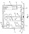
- the contact angle measurement apparatus 4 shown in Figure 1 in a schematic sectional side view is illustrated in its measurement position closely above the surface 6 of a solid sample body 7, which surface 6 is preferably oriented horizontally. It can be seen that a drop 8 is disposed on the surface 6.
- the contact angle measurement apparatus 4 is operable to determine the angle between a tangent of the contour of the drop 8 and the surface 6 of the sample body 7 at a point where the contour and the surface 6 meet, i.e. which is common to the surface 6 and the contour.
- the tangent extends in the plane of the Figure.
- the apparatus 4 comprises inside a housing 5 a camera 10.
- the optical axis A-A of the camera 10 extends perpendicularly to the surface 6 of the sample body 7.
- the camera 10 includes a lens 12, which is preferably focusable automatically.
- Projecting from the bottom side of the housing 5 is a total-reflection prism 14 which serves as a deflection means for the imaging beam path of the camera 10.
- the prism 14 enables recording an image of the drop 8 by the camera 10 in side view parallel or essentially parallel to the surface 6. Total reflection is occurring at the side face 16 of the prism 14.
- the apparatus 4 further comprises an illuminating device 20 which is disposed opposite the camera 10 on the other side of the drop 8.
- the illuminating device 20 includes an illuminating unit 21 and a spring suspension arrangement 23 mounted inside the housing 5 and carrying the illuminating unit 21 in such a manner that the illuminating unit 21 projects or may project from the bottom side of the housing 5 and - in operation, i.e. in the measurement position illustrated in Figure 1 - can be elastically pressed against the surface 6 while contacting the surface 6 with a defined portion, such as an edge of the illuminating unit 21.
- the spring suspension arrangement 23 may preferably comprise one or more leaf springs (not shown) which are arranged and constructed to allow for guided movement of the illuminating unit 21 in a direction parallel to the optical axis A-A.
- the leaf spring or leaf springs provide a substantially higher resistance against movement perpendicularly to the optical axis A-A than against movement parallel to this direction.
- the illuminating unit 21 comprises a light source 22 and a light diffuser 24 arranged such that light emitted by the light source 22 passes through the light diffuser 24.
- the illuminating unit 21 is mounted and oriented in such a manner that - in the measurement position illustrated in Figure 1 - the light diffuser 24 is disposed between the prism 14 (and the drop 8) and the light source 22.
- the illuminating unit 21 is disposed close to the surface 6 of the sample body 7 and is operable to illuminate the drop 8 from a side along or essentially along the surface 6 with light emitted by the light source 22 and diffused by the diffuser 24 for homogenization purposes.
- the drop 8 is illuminated from the left side, so that a back-lit lighting arrangement is created for the camera 10 and a shadow image of the drop 8 can be recorded by the camera 10, allowing for determining the contour of the drop 8.
- the apparatus 4 further includes two drop dosing devices 30, only one of which is visible in Figure 1 (the other drop dosing device 30 is located behind the drop dosing device 30 visible in Figure 1 , i.e. behind the plane of the drawing, and can be seen in Figure 2 , and accordingly a drop 8 formed by the other drop dosing device 30 is positioned spaced from the drop 8 visible in Figure 1 behind the latter drop 8).
- Each of the drop dosing devices 30 comprises a tube, needle or cannula 31, a nozzle 32 which projects downwardly towards the surface 6 from an opening 33 provided in the bottom side of the housing 5, such that it is spaced from the surface 6, i.e. such that the nozzle 32 projects less from the bottom side of the housing 5 than both the prism 14 and the illuminating unit 21.
- the nozzle 32 provides an outlet from which liquid transported within the tube or needle 31 can exit to form the drop 8.
- the liquid reservoir arrangement 35 includes two liquid reservoirs 36 in which two different liquids of different polarity are stored, and each tube or needle 31 of the two drop dosing devices 30 is in fluid communication with a different one of the two liquid reservoirs 36, so that the drop dosing devices 30 form drops 8 of the different liquids.
- the apparatus 4 comprises within the housing 5 an air system 37 which is operable to provide pressurized air at a defined pressure to the liquid reservoir arrangement 35 and the drop dosing device 30 in order to pressurize the liquids stored in the liquid reservoirs 36 for forcing them under pressure through the tubes or needles 31 and out of the outlets at the nozzles 32 in liquid jets onto the surface 6 to form the drops 8.
- the tube or needle 31 of each of the drop dosing devices 30 is normally blocked near the nozzle 32 by a valve 38, which is connected to a controller 39 adapted for controlling opening and closing of the valve 38.
- the controller 39 controls the valve 38 to open for a defined period of time, during which the liquid from the respective liquid reservoir 36 pressurized by the pressurized air is forced by the pressure out of the outlet of the respective nozzle 32, and to then close again, thereby allowing formation of a drop 8, which may advantageously have a defined volume.
- the nozzle 32 and the valve 38 of each of the drop dosing devices 30 may be provided as a single component, i.e. as a nozzle having an integrated valve.
- the controller 39 is also connected to each of the illuminating device 20, the liquid reservoir arrangement 35 and the air system 37 for controlling operation of these components, and to a processing device 40 operably connected to the camera 10.
- the processing device 40 in turn controls operation of the camera 10 and is adapted and operable to receive and analyze images recorded by the camera 10.
- both the controller 39 and the processing device 40 are shown as being disposed inside the housing 5.
- the controller 39 may be provided as a microcontroller.
- the controller 39 and/or the processing device 40 is provided as a separate device outside the housing 5, for example as a suitably programmed computer or PC.
- the air system 37, the liquid reservoir arrangement 35 and the two drop dosing devices 30 are shown in more detail in the schematic block diagram of Figure 2 .
- the air system 37 comprises an air inlet 41, a pump 42 pressurizing air received through the air inlet 41, two valves 43 and 44, a pressure sensor 46 located and operable to sense the pressure of the pressurized air, a throttle valve 47, a pressure relief outlet 48, and an outlet 49 coupled in fluid communication to the liquid reservoir arrangement 35 for providing pressurized air to the liquid reservoirs 36.
- the controller 39 is adapted to function, amongst others, as a pressure regulator, which is operable to regulate the pressure of the pressurized air.
- Adjustment of the pressure of the pressurized air towards higher values can involve suitably adjusting operation of the pump 42, and adjustment of the pressure of the pressurized air towards lower values can be effected by suitably opening the valve 44 in order to relief pressure through the throttle valve 47 and the pressure relief outlet 48, wherein the throttle valve 47 limits maximum flow.
- the sensor 46, the valve 44, and the pump 42 are connected to the controller 39 such that the pressure regulator implemented by the controller 39 receives sensor signals from the sensor 46 and is able to control operation of the valve 44, and the pump 42 (and possibly also the valve 43) based on the sensed pressure in order to adjust the pressure at the outlet 49 to the defined pressure.
- the valve 43 is provided for avoiding an undesired pressure drop upon switching off the pump 42.
- the pressurized air is provided through the outlet 49 to an air reservoir portion 36a of each of the two liquid reservoirs 36, each of which air reservoir portion 36a is separated from a liquid reservoir portion 36c, in which the liquid is actually stored, by a gas-liquid separator 36b.
- the liquids stored in the liquid reservoir portions 36c are pressurized by the pressurized air, thereby driving them out of the liquid reservoir portions 36c, through the tubes or needles 31 and out of the outlets at the nozzles 32 upon opening the valves 38.
- an operator positions the apparatus 4 above the surface 6 of the sample body 7 in the position illustrated in Figure 1 and presses a button 50 mounted on the housing 5 and connected to the controller 39.
- the controller 39 is adapted to detect pressing of the button 50 and to then initiate an automatic control sequence, in which - possibly following control or adjustment of the pressure of the pressurized air by checking the pressure sensed by the pressure sensor 46 and operating the pressure regulator in the manner described above - the valves 38 are opened, e.g. simultaneously, for a defined period of time in order to apply the liquids in jets to the surface 6 to form two drops 8 next to each other, and to then close the valves 38 again.
- the illuminating device 20 is controlled to illuminate the drops 8 from the left-hand side in Figure 1 , and the camera 10 is operated - via the processing device 40 or alternatively via the controller 39 - to record a shadow image of both drops 8 viewing them from the right-hand side in Figure 1 .
- the processing device 40 receives the image and carries out a contour analysis for both drops 8 and subsequently a determination of the contact angle for each drop 8. Further, the processing device 40 may be adapted to determine the surface free energy from the two contact angles. Thus, the measurement is carried out automatically in a very simple manner by simply pressing the button 50.
- the controller 39 is adapted to adjust the defined pressure of the pressurized air and/or the degree of opening of the valve 38 in such a manner that for each drop dosing device 30 the liquid is applied to the surface in the jet with a flow rate of 45 ⁇ l/s or less, preferably about 40 ⁇ l/s or less, more preferably about 35 ⁇ l/s or less, even more preferably about 30 ⁇ l/s or less, and most preferably 25 ⁇ l/s or about 25 ⁇ l/s.
- the nozzle 32 is configured such that the ratio of the diameter of the jet of liquid exiting the outlet at the tip 32 and the diameter of a finished drop having a contact angle of 90° is 0.2 or less.
- the nozzles 32 may be configured such that, under control of the controller 39, they can be opened with variable flow cross-sections in order to change the jet diameter.
- the apparatus 4 generally may also comprise a compressed gas system using a gas different than air, such as, e.g., CO 2 .
- a compressed gas system is constructed and operating identically to the air system described above, with the only difference being that a gas other than air is used.
- a system directly pressurizing the liquids e.g. by means of suitable pumps.
- drop dosing device 30 instead of the above-described drop dosing device 30 shown in the Figures and being air operated, other types of drop dosing devices may be used in the apparatus 4, such as, e.g., syringe type drop dosing devices.
- Figure 3 illustrates, in a schematic top view, the field of view of the camera 10 and the illumination of the drop by the illuminating device 20.
- the light source 22 and the remainder of the illuminating device 20 are configured such that the drop 8 is illuminated from the left-hand side in Figures 1 and 3 in effect by a two-dimensional light field 60 (see also Figures 4 and 5 ).
- the camera 10 views both the drop 8 and the light field 60 from the side of the drop 8 opposite the light field 60.
- the illumination angle 61 of the drop 8 by the light field 60 as measured in a plane parallel to the surface 6 depends on the width of the light field 60, i.e. the dimension of the light field parallel to the surface 6. It can also be taken from Figure 3 that with increasing illumination angle 61 the drop 8 is increasingly illuminated also from the lateral sides in a direction perpendicular to the axis of the field of view of the camera 10. Conversely, such illumination from the lateral sides can be decreased by decreasing the width of the light field 60.
- the light source 22 may include a one- or two-dimensional array of light-emitting diodes, which can be switched on and off selectively by the controller 39 for adjusting the width, and possibly also the height, of the light field 60.
- This adjustment may preferably also be a part of the automatic operation sequence described above and initiated by pressing the button 50.
- the controller 39 may be adapted to control the camera 10 and the processing device 40 in such a manner that several images are recorded and the width of the light field 60 is adjusted in steps in order to maximize the width of the shadow image 63 of the drop 8.
- Figure 6 schematically illustrates a light source 22 including a one-dimensional array of nine anorganic light-emitting diodes 70
- Figure 7 schematically illustrates how the camera 10 views the drop 8 with the light field 60 created by the light source 22 and the light diffuser 24 visible on the opposite side behind the drop 8.
- the width of the light field 60 has been adapted to the width of the drop 8 by switching off the two left-most and the two right-most light-emitting diodes (indicated by crosshatching; one of these light-emitting diodes is designated with the reference numeral 70"), and only switching on the remaining light-emitting diodes (one of these light-emitting diodes is designated with the reference numeral 70').
- the light diffuser 24 advantageously may be constructed such that it comprises separate diffuser sections for the individual light-emitting diodes 70, which diffuser sections are separated such that each diffuser section receives - and diffuses
Landscapes
- Physics & Mathematics (AREA)
- Health & Medical Sciences (AREA)
- Life Sciences & Earth Sciences (AREA)
- Chemical & Material Sciences (AREA)
- Analytical Chemistry (AREA)
- Biochemistry (AREA)
- General Health & Medical Sciences (AREA)
- General Physics & Mathematics (AREA)
- Immunology (AREA)
- Pathology (AREA)
- Length Measuring Devices By Optical Means (AREA)
Description
- The present application relates to a contact angle measurement apparatus for measuring a contact angle between a surface of a sample body and at least one drop of sample liquid disposed on the surface, the apparatus comprising at least one drop dosing device adapted and arranged for applying a drop of a liquid onto a surface of a sample body, an illuminating device adapted and arranged for illuminating each drop applied by the at least one drop dosing device and disposed on the surface from a first side of the at least one drop, and an image recording device adapted and arranged for recording an image of at least a transition region between the surface and each drop applied by the at least one drop dosing device and disposed on the surface in side view from a second side of the drop opposite the first side, wherein the illuminating device comprises a light-emitting arrangement which, when viewed by the image recording device, provides a two-dimensional light field.
- The wettability of liquids on surfaces of solids is of great importance in many fields of technology, such as in the field of industrial production. For example, processes such as coating, painting, cleaning, printing, hydrophobic or hydrophilic coating, bonding, dispersion, etc. are influenced in a decisive manner by the wettability.
- For a particular pair of solid and liquid the wettability is determined by, amongst others, the surface free energy of the solid and the surface tension of the liquid. In view of the fact that, following application of the liquid onto a surface of the solid, these parameters also determine the angle between the surface of the liquid and the surface of the solid at the point at which the surface of the liquid meets the surface of the solid, a measurement of this so-called contact angle can be used as a measure of the wettability. On this basis methods are known for characterizing surfaces of solid bodies with respect to their wettability properties by applying one or more drops of liquids having known properties (in particular known surface tensions) and serving as "sensors" onto a surface of interest and measuring the corresponding contact angle or angles. When using two or more different liquids having a different degree of polarity, it is further possible to derive the surface free energy from the measured contact angles of drops of the different liquids.
-
DE 197 54 765 C1 discloses a contact angle measurement apparatus which is adapted for carrying out methods of these types. It includes a syringe type drop dosing device adapted for metering a drop of liquid onto a surface of a solid sample body, an illuminating device adapted and arranged for illuminating the drop from a first side and a camera for recording a shadow image of the drop from a second side opposite the first side. Further, an image processing device is provided which is adapted to carry out a recognition of the contour of the drop and of the surface of the solid in the image recorded by the camera and to subsequently determine the contact angle based on the recognized contour and surface. - Since the measurements effected by an apparatus of the type as disclosed in
DE 197 54 765 C1 rely on a camera recording a "perfect" shadow image of a drop in a back-lit lighting arrangement, and because most liquids used as sensor liquids reflect considerable portions of light emitted by illuminating devices, without taking complex measures the precision of contact angle measurements can be affected by reflections occurring on the drop surfaces, which reflections disturb the per-fectness of the recorded shadow image. - From the document
JP2011179974A - It is an object of the present invention to provide a contact angle measurement apparatus which is of a simple construction and easy to use and nevertheless guarantees high precision measurements, and which overcomes the above disadvantages.
- This object is achieved by a contact angle measurement apparatus according to claim 1. Advantageous embodiments of the apparatus are the subject-matter of the respective dependent claims.
- The contact angle measurement apparatus is adapted to measure a contact angle between a surface of a solid sample body and one or more drops of sample liquid disposed on the surface. In case of two or more drops, which may be drops disposed on the surface next to each other at the same time or drops disposed on the surface at different points in time, the contact angle is measured for each drop of interest.
- The apparatus includes one, two or more drop dosing devices. Each of these drop dosing devices is adapted and arranged for applying a drop of a liquid onto a surface of a sample body. This process is carried out by metering the drop, which may advantageously be effected such that it has a defined drop volume. Each of the drop dosing devices may include an internal fluid storing volume which has to be filled manually or automatically with a suitable liquid prior to applying a drop of that liquid to the surface. For example, syringe type drop dosing devices may be used which are releasably coupled to the apparatus and can be selectively removed in order to fill the internal fluid storing volume in the usual manner.
- Irrespective of the particular type of drop dosing device it may be advantageous if the apparatus also comprises a liquid reservoir arrangement for storing one, two or more liquids. Such a liquid reservoir arrangement can be provided instead of or in addition to an internal fluid storing volume as described above. The liquid reservoir arrangement has one, two or more liquid reservoirs, and each of the drop dosing devices is in fluid communication with the liquid reservoir arrangement, more particularly with at least one of the liquid reservoirs of the liquid reservoir arrangement. In case two or more liquids are to be used, the liquid reservoir arrangement preferably includes a corresponding number of separate liquid reservoirs, each adapted for storing a different one of the liquids. In operation, liquid or liquids to be used for forming drops on a surface of a sample body is or are stored in the liquid reservoir arrangement, more particularly in a liquid reservoir or liquid reservoirs of the liquid reservoir arrangement, and can be delivered manually or preferably automatically to the drop dosing devices. In case two or more drop dosing devices are provided, they may be coupled to the liquid reservoir arrangement such that they apply the same liquid to different locations on the surface, e.g. in order to determine variations of the surface properties. However, as will be explained in more detail further below, it is preferred for two or more drop dosing devices being coupled to different liquid reservoirs of the liquid reservoir arrangement storing different liquids.
- Moreover, in any case the apparatus comprises an illuminating device and an image recording device. The illuminating device is adapted and arranged for illuminating any drop applied by the drop dosing device or drop dosing devices and disposed on the surface from a first side of the respective drop, and the image recording device is adapted and arranged for recording an image of any such drop or of at least a transition region between the surface and any such drop in side view from a second side of the drop opposite the first side. Thus, the relative arrangement of the illuminating device and the image recording device is such that images of drops can be recorded in a back-lit lighting arrangement to obtain shadow images of the drops. It is to be noted that a separate image may be recorded for each of the above drops, or a single image may be recorded for a plurality of the above drops or all of the above drops.
- The illuminating device comprises a light-emitting arrangement which, when viewed by the image recording device, i.e. in images recorded by the image recording device, provides a two-dimensional light field. In other words, the light-emitting arrangement creates the two-dimensional light field behind the drops in images recorded by the image recording device. The contact angle measurement apparatus further comprises a controller connected to the illuminating device. The controller and the light-emitting arrangement are adapted such that one or two dimensions of the light field are selectively adjustable by the controller. Advantageously, the controller may be an electronic component which may be integrated into a common housing with some or all of the remaining components of the apparatus. However, it is, e.g., also possible to provide the controller as a separate computing device, such as a suitably programmed computer or PC, connected to the remainder of the apparatus and not integrated into a common housing with other components of the apparatus.
- As will be explained below with reference to
Figures 3 to 5 , it has been found that measurement errors caused by reflections can be minimized by adapting the dimensions and, preferably, at least the width of the light field to the dimensions of the drop or drops illuminated by the illuminating device. More specifically, the dimensions of the light field should be chosen smaller with decreasing drop size. The above configuration of the controller and the illuminating device provide the advantage that such adaptation is easily and flexibly possible and may be subject to automatic control. In the case of two or more drops it is advantageous to provide for the possibility to illuminate each drop separately by choosing in each case the dimensions of the light field in such a manner that only the drop at issue is illuminated. In effect, the light field can then be divided into separate zones for the different drops, with the zones being switched on one at a time and the dimensions of each zone being adapted to the respective drop to minimize measurement errors as described above. Drops applied to the surface by the apparatus generally may have a diameter of, e.g., 4 mm or less and preferably 2 mm or less when applied to have a contact angle of 90°, and multiple drops may have a distance between the centers of the drops of, e.g., about 6 mm. - In an advantageous embodiment the entire apparatus may be constructed as a mobile apparatus. It is easily possible to select suitable components for the construction of the apparatus, which components are of sufficiently small dimensions. However, depending on the application at issue, the entire apparatus or at least parts of the apparatus may also be constructed to be stationary, i.e. non-mobile.
- It is to be noted that the apparatus may be used both for planar and for curved surfaces, wherein the construction of the apparatus determines the allowable maximum curvature in that it must be possible to record shadow images of the drops in the manner described above. The apparatus may include a support structure by means of which it can be supported on the surface on which the measurement is to be carried out and/or by means of which it can be suspended above the surface. Of course, it is also possible that the apparatus is held in its measurement position above or on the surface by a suitable external holding means. Such support structure or holding means may be constructed to be adjustable in order to allow for adaptability to surfaces of different shapes. In addition or in the alternative, the illuminating device and/or the image recording device may be constructed to have adjustable positions in order to allow for such adaptability.
- The light-emitting arrangement comprises a plurality of light-emitting elements arranged in an array for providing the two-dimensional light field. The controller is then adapted to adjust at least one dimension of the light field by selectively switching on and off the light-emitting elements. The array may be one- or two-dimensional. In the case of a one-dimensional array, the second dimension of the light field must be provided by a suitable size or extension of the light-emitting elements in the corresponding direction. Adjusting dimensions of the light field by switching on and off light-emitting elements is particularly simple to realize and can easily be effected by way of automatic control by the controller.
- The light-emitting elements are preferably light-emitting diodes, which may be selected, e.g., from the group consisting of monochromatic light-emitting diodes and white light-emitting diodes. In particular, the light-emitting diodes may be anorganic light-emitting diodes or organic light-emitting diodes (OLEDs). Due to their small size, OLEDs may be advantageously in cases in which it is desired to create a light field having a "high resolution", so that the dimension or dimensions can be changed in very small steps.
- The light-emitting arrangement may comprise a light diffuser, which is mounted with respect to the light-emitting elements in such a manner that the light emitted by the light-emitting elements passes through the light diffuser, so that the light field is generated by light emitted by the light-emitting elements and diffused by the light diffuser. The light diffuser is preferably provided as a plate or block of suitable translucent material completely covering the array of the light-emitting elements on a side to which the light-emitting elements emit light. The light field is then provided on a surface of the light diffuser opposite the light-emitting elements. The light diffuser is particularly advantageous in cases in which, due to constructive characteristics of the light-emitting elements, relatively large gaps have to be provided between adjacent light-emitting elements, and then serves to provide a light field with a homogeneous light distribution.
- In the alternative, it may be advantageous if the light field is generated directly by the light-emitting elements, i.e. that no diffuser is provided. In order to ensure a homogeneous light distribution, this requires small gaps between adjacent light-emitting elements. This can be realized, for example, by OLEDs.
- In a preferred embodiment the illuminating device includes an illuminating unit and a spring suspension arrangement carrying the illuminating unit, wherein the illuminating unit comprises the light-emitting arrangement and is arranged in such a manner that it can rest on the surface of the sample body while being pressed against the surface by a spring force applied by the spring suspension means. For example, the illuminating unit may be arranged such that it can project partly or completely out of a housing of the apparatus.
- In a preferred embodiment the light-emitting arrangement comprises a diaphragm having an adjustable aperture. The controller is connected to the diaphragm and adapted to adjust at least one dimension of the light field by selectively adjusting the aperture of the diaphragm.
- In embodiments in which only one dimension of the light field is adjustable by the controller, a diaphragm having an adjustable aperture may also be provided which is manually adjustable in order to allow for manual adjustment of a further dimension of the light field. For example, in the above-described embodiment having a one-dimensional array of light-emitting elements allowing for an adjustment of the width of the light field by selectively switching on and off the light-emitting elements, a manually adjustable diaphragm could be provided to enable manual adjustment of the height of the light field.
- The light-emitting arrangement may comprise a lens and/or a light-deflecting element, such as, e.g., a deflecting mirror or prism. Such a configuration advantageously allows for flexibility in the positioning of the above-described light-emitting elements arranged in an array. However, it is preferred, in particular when providing an illuminating unit as described above, to position the above-described light-emitting elements arranged in an array, on a side of the drops opposite to the side from which the images are recorded.
- In a preferred embodiment, the controller and the light-emitting arrangement are adapted such that at least the width of the light field, when viewed by the image recording device (i.e. the dimension parallel to the surface), is selectively adjustable by the controller. This dimension is particularly important for minimizing reflections and associated measurement errors. In this regard, it may be advantageous if the controller and the light-emitting arrangement are adapted such that both the width and the height of the light field, when viewed by the image recording device (i.e. also the dimension perpendicular to the surface), are selectively adjustable by the controller.
- In a preferred embodiment, the contact angle measurement apparatus further comprises a processing device, which is connected to or forms part of the image recording device and which is adapted to receive an image from the image recording device representing a shadow image of a drop on the surface, to analyze the received image, and to cooperate with the controller to automatically effect adjustment of at least one dimension of the light field based on the result of the analysis in order to maximize the respective at least one dimension of the shadow image of the drop. By adjusting a dimension and in particular the width of the light field to maximize the respective dimension of the shadow image, reflections are minimized. The adjustment may involve adjusting the at least one dimension in several steps and recording a new image after each adjustment step. Automatic adjustment facilitates use of the apparatus and obtaining precise measurement results. The processing device and the controller may also be provided as a single device.
- In a preferred embodiment, each of the drop dosing devices is arranged to apply drops of liquid in a field of view of the image recording device and/or in a region illuminated by the light field. Consequently, the image recording device, the sample body and/or the illuminating device do not have to be moved after application of a drop, thereby decreasing the time necessary for recording an image of the drop after its application.
- In this embodiment, but also in general, it is preferred if the drop dosing device or drop dosing devices, the illuminating device and the image recording device are integrated into a movable measurement head. This provides for a particularly easy to use configuration.
- The image recording device may be a camera or a device including a light-sensitive sensor, such as, e.g., a CCD image sensor or a CMOS image sensor. Thus, the image recording device may be, e.g., a CCD or CMOS camera.
- In a preferred embodiment, the contact angle measurement apparatus further comprises a processing device, which is connected to or forms part of the image recording device and which is adapted for carrying out a contour recognition of any drops present in images recorded by the image recording device and determining for each of these drops a contact angle from the recognized contour. The contour recognition may be based, e.g., on a grey-scale analysis of the image and then fitting a geometrical model describing the drop shape to the image in order to determine the contour. If this embodiment is combined with an embodiment described above implementing an automatic adjustment of at least one dimension of the light field to maximize the respective dimension of the shadow image and to minimize reflections, a single processing devices is preferably used.
- In a preferred embodiment, the contact angle measurement apparatus further comprises an actuation means, such as a button or switch, for actuation by an operator and connected to the controller. The controller is adapted to detect actuation of the actuation means and, upon detecting actuation, to automatically control the drop dosing device or drop dosing devices to apply a respective drop of liquid to the surface, the illuminating device to illuminate each such drop including adjusting at least one dimension of the light field, and the image recording device to record an image of each such drop illuminated by the illuminating device. In particular, the above-described automatic optimization of the light field dimension or dimensions is advantageous in this embodiment. Thus, a "one click solution" is provided which greatly simplifies use of the apparatus. In case the apparatus includes a processing device of the above configuration for carrying out contour recognition and contact angle determination, the one click solution advantageously also comprises automatically controlling the processing device by the controller to determine the contact angle for each of the drops. Consequently, it is only necessary for the operator to move the contact angle measurement apparatus into a suitable position above the surface and to actuate the actuation means, and subsequently the apparatus is operating autonomously until the desired measurement results are provided.
- In the following an exemplary embodiment of the display device will be explained in more detail with reference to the drawings.
-
Figure 1 shows a schematic sectional side view of the contact angle measurement apparatus according to an embodiment of the present invention. -
Figure 2 shows a schematic block diagram of two drop dosing devices used in the contact angle measurement apparatus ofFigure 1 . -
Figure 3 shows a schematic top view of a part of the measuring arrangement of the apparatus ofFigure 1 for measuring the contact angle of a single drop. -
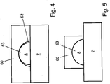
Figure 4 shows a schematic side view of the drop ofFigure 3 as viewed by the camera of the apparatus ofFigure 1 in a first adjustment state of the illuminating device. -
Figure 5 shows a schematic side view of the drop ofFigure 3 as viewed by the camera of the apparatus ofFigure 1 in a second adjustment state of the illuminating device. -
Figure 6 shows a schematic side view of a light source of the illuminating device. -
Figure 7 shows a schematic side view of the drop ofFigure 3 as viewed by the camera of the apparatus ofFigure 1 when using the light source ofFigure 6 . - The contact
angle measurement apparatus 4 shown inFigure 1 in a schematic sectional side view is illustrated in its measurement position closely above thesurface 6 of asolid sample body 7, which surface 6 is preferably oriented horizontally. It can be seen that adrop 8 is disposed on thesurface 6. The contactangle measurement apparatus 4 is operable to determine the angle between a tangent of the contour of thedrop 8 and thesurface 6 of thesample body 7 at a point where the contour and thesurface 6 meet, i.e. which is common to thesurface 6 and the contour. In the illustration ofFigure 1 the tangent extends in the plane of the Figure. For a correct fitting of the tangent to the contour of thedrop 8 it is necessary that thedrop 8 or at least a transition region between thedrop 8 and thesurface 6 of thesample body 7 is imaged in side view, which in the case ofFigure 1 is done by viewing thedrop 8 from the right. - For this purpose, the
apparatus 4 comprises inside a housing 5 acamera 10. The optical axis A-A of thecamera 10 extends perpendicularly to thesurface 6 of thesample body 7. However, when suitably adapting the imaging beam path, it is also possible to provide an angle between the optical axis A-A and thesurface 6 different from 90°. Thecamera 10 includes alens 12, which is preferably focusable automatically. Projecting from the bottom side of thehousing 5 is a total-reflection prism 14 which serves as a deflection means for the imaging beam path of thecamera 10. Theprism 14 enables recording an image of thedrop 8 by thecamera 10 in side view parallel or essentially parallel to thesurface 6. Total reflection is occurring at theside face 16 of theprism 14. - The
apparatus 4 further comprises an illuminatingdevice 20 which is disposed opposite thecamera 10 on the other side of thedrop 8. The illuminatingdevice 20 includes an illuminatingunit 21 and aspring suspension arrangement 23 mounted inside thehousing 5 and carrying the illuminatingunit 21 in such a manner that the illuminatingunit 21 projects or may project from the bottom side of thehousing 5 and - in operation, i.e. in the measurement position illustrated inFigure 1 - can be elastically pressed against thesurface 6 while contacting thesurface 6 with a defined portion, such as an edge of the illuminatingunit 21. Thespring suspension arrangement 23 may preferably comprise one or more leaf springs (not shown) which are arranged and constructed to allow for guided movement of the illuminatingunit 21 in a direction parallel to the optical axis A-A. In other words, the leaf spring or leaf springs provide a substantially higher resistance against movement perpendicularly to the optical axis A-A than against movement parallel to this direction. - In the illustrated advantageous embodiment the illuminating
unit 21 comprises alight source 22 and a light diffuser 24 arranged such that light emitted by thelight source 22 passes through the light diffuser 24. The illuminatingunit 21 is mounted and oriented in such a manner that - in the measurement position illustrated inFigure 1 - the light diffuser 24 is disposed between the prism 14 (and the drop 8) and thelight source 22. Like theprism 14, in the measurement condition of theapparatus 4 the illuminatingunit 21 is disposed close to thesurface 6 of thesample body 7 and is operable to illuminate thedrop 8 from a side along or essentially along thesurface 6 with light emitted by thelight source 22 and diffused by the diffuser 24 for homogenization purposes. In the schematic representation ofFigure 1 , thedrop 8 is illuminated from the left side, so that a back-lit lighting arrangement is created for thecamera 10 and a shadow image of thedrop 8 can be recorded by thecamera 10, allowing for determining the contour of thedrop 8. - For applying
drops 8 to thesurface 6 of thesample body 7, theapparatus 4 further includes twodrop dosing devices 30, only one of which is visible inFigure 1 (the otherdrop dosing device 30 is located behind thedrop dosing device 30 visible inFigure 1 , i.e. behind the plane of the drawing, and can be seen inFigure 2 , and accordingly adrop 8 formed by the otherdrop dosing device 30 is positioned spaced from thedrop 8 visible inFigure 1 behind the latter drop 8). Each of thedrop dosing devices 30 comprises a tube, needle orcannula 31, anozzle 32 which projects downwardly towards thesurface 6 from an opening 33 provided in the bottom side of thehousing 5, such that it is spaced from thesurface 6, i.e. such that thenozzle 32 projects less from the bottom side of thehousing 5 than both theprism 14 and the illuminatingunit 21. Thenozzle 32 provides an outlet from which liquid transported within the tube orneedle 31 can exit to form thedrop 8. - At the
end 34 of the tube orneedle 31 opposite thenozzle 32 the tube orneedle 31 is connected to aliquid reservoir arrangement 35. Theliquid reservoir arrangement 35 includes twoliquid reservoirs 36 in which two different liquids of different polarity are stored, and each tube orneedle 31 of the twodrop dosing devices 30 is in fluid communication with a different one of the twoliquid reservoirs 36, so that thedrop dosing devices 30 form drops 8 of the different liquids. - Further, the
apparatus 4 comprises within thehousing 5 anair system 37 which is operable to provide pressurized air at a defined pressure to theliquid reservoir arrangement 35 and thedrop dosing device 30 in order to pressurize the liquids stored in theliquid reservoirs 36 for forcing them under pressure through the tubes or needles 31 and out of the outlets at thenozzles 32 in liquid jets onto thesurface 6 to form the drops 8. - The tube or
needle 31 of each of thedrop dosing devices 30 is normally blocked near thenozzle 32 by avalve 38, which is connected to acontroller 39 adapted for controlling opening and closing of thevalve 38. Thus, for applying adrop 8 to thesurface 6 thecontroller 39 controls thevalve 38 to open for a defined period of time, during which the liquid from therespective liquid reservoir 36 pressurized by the pressurized air is forced by the pressure out of the outlet of therespective nozzle 32, and to then close again, thereby allowing formation of adrop 8, which may advantageously have a defined volume. In an alternative embodiment thenozzle 32 and thevalve 38 of each of thedrop dosing devices 30 may be provided as a single component, i.e. as a nozzle having an integrated valve. - The
controller 39 is also connected to each of the illuminatingdevice 20, theliquid reservoir arrangement 35 and theair system 37 for controlling operation of these components, and to aprocessing device 40 operably connected to thecamera 10. Theprocessing device 40 in turn controls operation of thecamera 10 and is adapted and operable to receive and analyze images recorded by thecamera 10. - In the illustrated embodiment both the
controller 39 and theprocessing device 40 are shown as being disposed inside thehousing 5. For example, thecontroller 39 may be provided as a microcontroller. However, it is also possible that thecontroller 39 and/or theprocessing device 40 is provided as a separate device outside thehousing 5, for example as a suitably programmed computer or PC. - The
air system 37, theliquid reservoir arrangement 35 and the twodrop dosing devices 30 are shown in more detail in the schematic block diagram ofFigure 2 . - As can be seen in
Figure 2 , theair system 37 comprises anair inlet 41, apump 42 pressurizing air received through theair inlet 41, twovalves pressure sensor 46 located and operable to sense the pressure of the pressurized air, athrottle valve 47, apressure relief outlet 48, and anoutlet 49 coupled in fluid communication to theliquid reservoir arrangement 35 for providing pressurized air to theliquid reservoirs 36. Thecontroller 39 is adapted to function, amongst others, as a pressure regulator, which is operable to regulate the pressure of the pressurized air. Adjustment of the pressure of the pressurized air towards higher values can involve suitably adjusting operation of thepump 42, and adjustment of the pressure of the pressurized air towards lower values can be effected by suitably opening thevalve 44 in order to relief pressure through thethrottle valve 47 and thepressure relief outlet 48, wherein thethrottle valve 47 limits maximum flow. For this purpose, thesensor 46, thevalve 44, and the pump 42 (and possibly also the valve 43) are connected to thecontroller 39 such that the pressure regulator implemented by thecontroller 39 receives sensor signals from thesensor 46 and is able to control operation of thevalve 44, and the pump 42 (and possibly also the valve 43) based on the sensed pressure in order to adjust the pressure at theoutlet 49 to the defined pressure. Thevalve 43 is provided for avoiding an undesired pressure drop upon switching off thepump 42. - In
Figure 2 it is further shown that the pressurized air is provided through theoutlet 49 to anair reservoir portion 36a of each of the twoliquid reservoirs 36, each of whichair reservoir portion 36a is separated from aliquid reservoir portion 36c, in which the liquid is actually stored, by a gas-liquid separator 36b. In this manner, the liquids stored in theliquid reservoir portions 36c are pressurized by the pressurized air, thereby driving them out of theliquid reservoir portions 36c, through the tubes or needles 31 and out of the outlets at thenozzles 32 upon opening thevalves 38. - For carrying out a contact angle and surface free energy measurement with two
drops 8, an operator positions theapparatus 4 above thesurface 6 of thesample body 7 in the position illustrated inFigure 1 and presses abutton 50 mounted on thehousing 5 and connected to thecontroller 39. Thecontroller 39 is adapted to detect pressing of thebutton 50 and to then initiate an automatic control sequence, in which - possibly following control or adjustment of the pressure of the pressurized air by checking the pressure sensed by thepressure sensor 46 and operating the pressure regulator in the manner described above - thevalves 38 are opened, e.g. simultaneously, for a defined period of time in order to apply the liquids in jets to thesurface 6 to form twodrops 8 next to each other, and to then close thevalves 38 again. Then, the illuminatingdevice 20 is controlled to illuminate thedrops 8 from the left-hand side inFigure 1 , and thecamera 10 is operated - via theprocessing device 40 or alternatively via the controller 39 - to record a shadow image of bothdrops 8 viewing them from the right-hand side inFigure 1 . Theprocessing device 40 receives the image and carries out a contour analysis for bothdrops 8 and subsequently a determination of the contact angle for eachdrop 8. Further, theprocessing device 40 may be adapted to determine the surface free energy from the two contact angles. Thus, the measurement is carried out automatically in a very simple manner by simply pressing thebutton 50. - Preferably, the
controller 39 is adapted to adjust the defined pressure of the pressurized air and/or the degree of opening of thevalve 38 in such a manner that for eachdrop dosing device 30 the liquid is applied to the surface in the jet with a flow rate of 45 µl/s or less, preferably about 40 µl/s or less, more preferably about 35 µl/s or less, even more preferably about 30 µl/s or less, and most preferably 25 µl/s or about 25 µl/s. - Further, it is preferred if for each
drop dosing device 30 thenozzle 32 is configured such that the ratio of the diameter of the jet of liquid exiting the outlet at thetip 32 and the diameter of a finished drop having a contact angle of 90° is 0.2 or less. In case different drop sizes shall be possible, thenozzles 32 may be configured such that, under control of thecontroller 39, they can be opened with variable flow cross-sections in order to change the jet diameter. - Instead of the air system, the
apparatus 4 generally may also comprise a compressed gas system using a gas different than air, such as, e.g., CO2. Such a compressed gas system is constructed and operating identically to the air system described above, with the only difference being that a gas other than air is used. Further, it is also possible to utilize a system directly pressurizing the liquids, e.g. by means of suitable pumps. - It should be noted that instead of the above-described
drop dosing device 30 shown in the Figures and being air operated, other types of drop dosing devices may be used in theapparatus 4, such as, e.g., syringe type drop dosing devices. - For a
single drop 8 on thesurface 6Figure 3 illustrates, in a schematic top view, the field of view of thecamera 10 and the illumination of the drop by the illuminatingdevice 20. Thelight source 22 and the remainder of the illuminatingdevice 20 are configured such that thedrop 8 is illuminated from the left-hand side inFigures 1 and3 in effect by a two-dimensional light field 60 (see alsoFigures 4 and 5 ). Thecamera 10 views both thedrop 8 and thelight field 60 from the side of thedrop 8 opposite thelight field 60. - As can be taken from
Figure 3 , theillumination angle 61 of thedrop 8 by thelight field 60 as measured in a plane parallel to thesurface 6 depends on the width of thelight field 60, i.e. the dimension of the light field parallel to thesurface 6. It can also be taken fromFigure 3 that with increasingillumination angle 61 thedrop 8 is increasingly illuminated also from the lateral sides in a direction perpendicular to the axis of the field of view of thecamera 10. Conversely, such illumination from the lateral sides can be decreased by decreasing the width of thelight field 60. - In
Figure 4 it is illustrated that illumination from the lateral sides causesreflections 62 at the corresponding sides of thedrop 8, whichreflections 62 disturb theshadow image 63 of thedrop 8 such that in images recorded by thecamera 10 thedrop 8 appears to be smaller than in reality. As shown inFigure 5 , by decreasing the width of thelight field 60 as compared toFigure 4 , thereflections 62 can be minimized or avoided altogether, such that theshadow image 63 recorded by thecamera 10 corresponds to the actual contour of thedrop 8. For creating thelight field 60, thelight source 22 may include a one- or two-dimensional array of light-emitting diodes, which can be switched on and off selectively by thecontroller 39 for adjusting the width, and possibly also the height, of thelight field 60. This adjustment may preferably also be a part of the automatic operation sequence described above and initiated by pressing thebutton 50. In this regard, thecontroller 39 may be adapted to control thecamera 10 and theprocessing device 40 in such a manner that several images are recorded and the width of thelight field 60 is adjusted in steps in order to maximize the width of theshadow image 63 of thedrop 8. -
Figure 6 schematically illustrates alight source 22 including a one-dimensional array of nine anorganic light-emittingdiodes 70, andFigure 7 schematically illustrates how thecamera 10 views thedrop 8 with thelight field 60 created by thelight source 22 and the light diffuser 24 visible on the opposite side behind thedrop 8. InFigure 7 , the width of thelight field 60 has been adapted to the width of thedrop 8 by switching off the two left-most and the two right-most light-emitting diodes (indicated by crosshatching; one of these light-emitting diodes is designated with thereference numeral 70"), and only switching on the remaining light-emitting diodes (one of these light-emitting diodes is designated with the reference numeral 70'). - The light diffuser 24 advantageously may be constructed such that it comprises separate diffuser sections for the individual light-emitting
diodes 70, which diffuser sections are separated such that each diffuser section receives - and diffuses - light essentially or at least predominantly from the associated light-emitting diode only.
- instead of the one- or two-dimensional array of anorganic light-emitting diodes - a two dimensional OLED array. Due to the fact that OLED elements are much smaller than light-emitting diodes, such an OLED array can create a light field with a high resolution, so that no light diffuser is required.
Claims (14)
- A contact angle measurement apparatus for measuring a contact angle between a surface (6) of a solid sample body (7) and at least one drop (8) of sample liquid disposed on the surface (6), the apparatus comprising:at least one drop dosing device (30) adapted and arranged for applying a drop (8) of a liquid onto a surface (6) of a sample body (7),an illuminating device (20) adapted and arranged for illuminating each drop (8) applied by the at least one drop dosing device (30) onto the surface (6) from a first side of the at least one drop (8), andan image recording device (10) adapted and arranged for recording an image of at least a transition region between the surface (6) and each drop (8) applied by the at least one drop dosing device (30) onto the surface (6) in side view from a second side of the drop (8) opposite the first side,wherein the illuminating device (20) comprises a light-emitting arrangement which, when viewed by the image recording device (10), provides a two-dimensional light field (60),wherein the contact angle measurement apparatus further comprises a controller (39) connected to the illuminating device (20), whereinthe light-emitting arrangement comprises a plurality of light-emitting elements (22, 70) for providing the two-dimensional light field (60), characterized in that the light emitting elements (22, 70) are arranged in an array and in that the controller (39) is adapted to adjust at least one dimension of the light field (60) by selectively switching on and off the light-emitting elements (70).
- The contact angle measurement apparatus according to claim 1, wherein the light-emitting elements (70) are anorganic light-emitting diodes or organic light-emitting diodes.
- The contact angle measurement apparatus according to claim 1 or claim 2, wherein the light-emitting arrangement comprises a light diffuser (24), which is mounted with respect to the light-emitting elements (22, 70) in such a manner that the light emitted by the light-emitting elements (22, 70) passes through the light diffuser (24), so that the light field (60) is generated by light emitted by the light-emitting elements (22, 70) and diffused by the light diffuser (24).
- The contact angle measurement apparatus according to claim 3, wherein the illuminating device (20) includes an illuminating unit (21) and a spring suspension arrangement (23) carrying the illuminating unit (21), wherein the illuminating unit (21) comprises the light-emitting arrangement and is arranged in such a manner that it can rest on the surface (6) of the sample body (7) while being pressed against the surface (6) by a spring force applied by the spring suspension means.
- The contact angle measurement apparatus according to claim 1 or claim 2, wherein the light field (60) is generated directly by the light-emitting elements (22, 70).
- The contact angle measurement apparatus according to any of the preceding claims, wherein the light-emitting arrangement comprises a diaphragm having an adjustable aperture, wherein the controller (39) is connected to the diaphragm and adapted to adjust at least one dimension of the light field (60) by selectively adjusting the aperture of the diaphragm.
- The contact angle measurement apparatus according to any of the preceding claims, wherein the controller (39) and the light-emitting arrangement are adapted such that at least the width of the light field (60), when viewed by the image recording device (10), is selectively adjustable by the controller (39).
- The contact angle measurement apparatus according to claim 7, wherein the controller (39) and the light-emitting arrangement are adapted such that both the width and the height of the light field (60), when viewed by the image recording device (10), are selectively adjustable by the controller (39).
- The contact angle measurement apparatus according to any of the preceding claims, wherein the contact angle measurement apparatus further comprises a processing device (40), which is connected to or forms part of the image recording device (10) and which is adapted to receive an image from the image recording device (10) representing a shadow image of a drop (8) on the surface (6), to analyze the received image, and to cooperate with the controller (39) to automatically effect adjustment of at least one dimension of the light field (60) based on the result of the analysis in order to maximize the respective at least one dimension of the shadow image of the drop (8).
- The contact angle measurement apparatus according to any of the preceding claims, wherein each of the at least one drop dosing device (30) is arranged to apply drops (8) of liquid in a field of view of the image recording device (10) and/or in a region illuminated by the light field (60).
- The contact angle measurement apparatus according to any of the preceding claims, wherein the at least one drop dosing device (30), the illuminating device (20) and the image recording device (10) are integrated into a movable measurement head.
- The contact angle measurement apparatus according to any of the preceding claims, wherein the image recording device (10) comprises a CCD or CMOS image sensor.
- The contact angle measurement apparatus according to any of the preceding claims, further comprising a processing device (40) adapted for carrying out a contour recognition of any drops (8) present in images recorded by the image recording device (10) and determining for each of these drops (8) a contact angle from the recognized contour.
- The contact angle measurement apparatus according to any of the preceding claims, further comprising an actuation means (50) for actuation by an operator and connected to the controller (39), wherein the controller (39) is adapted to detect actuation of the actuation means (50) and, upon detecting actuation, to automatically control the at least one drop dosing device (30) to apply a respective drop (8) of liquid to the surface (6), the illuminating device (20) to illuminate each drop (8) applied by the at least one drop dosing device (30) including adjusting at least one dimension of the light field (60), and the image recording device (10) to record an image of each of the drops (8) illuminated by the illuminating device (20).
Priority Applications (1)
| Application Number | Priority Date | Filing Date | Title |
|---|---|---|---|
| EP14152564.2A EP2899529B1 (en) | 2014-01-24 | 2014-01-24 | Contact angle measurement apparatus |
Applications Claiming Priority (1)
| Application Number | Priority Date | Filing Date | Title |
|---|---|---|---|
| EP14152564.2A EP2899529B1 (en) | 2014-01-24 | 2014-01-24 | Contact angle measurement apparatus |
Publications (2)
| Publication Number | Publication Date |
|---|---|
| EP2899529A1 EP2899529A1 (en) | 2015-07-29 |
| EP2899529B1 true EP2899529B1 (en) | 2016-10-12 |
Family
ID=50000826
Family Applications (1)
| Application Number | Title | Priority Date | Filing Date |
|---|---|---|---|
| EP14152564.2A Active EP2899529B1 (en) | 2014-01-24 | 2014-01-24 | Contact angle measurement apparatus |
Country Status (1)
| Country | Link |
|---|---|
| EP (1) | EP2899529B1 (en) |
Families Citing this family (5)
| Publication number | Priority date | Publication date | Assignee | Title |
|---|---|---|---|---|
| CN107505236A (en) * | 2017-09-13 | 2017-12-22 | 宁波新边界科学仪器有限公司 | A kind of contact angle measuring method and its device with new liquid distribution method |
| CN111665171B (en) * | 2020-07-14 | 2023-03-03 | 上海梭伦信息科技有限公司 | Wet contact angle measuring device and testing method thereof |
| EP4109072B1 (en) * | 2021-06-24 | 2023-06-21 | KRÜSS GmbH, Wissenschaftliche Laborgeräte | Method and apparatus for measuring a receding contact angle |
| FR3132572B1 (en) | 2022-02-08 | 2023-12-22 | Univ Aix Marseille | Method for measuring at least one interfacial physical property |
| CN116577243B (en) * | 2023-05-23 | 2025-12-23 | 帝泊尔计量检测研究院(深圳)有限公司 | A method, apparatus and system for measuring the angle of a water droplet |
Family Cites Families (4)
| Publication number | Priority date | Publication date | Assignee | Title |
|---|---|---|---|---|
| DE19754765C1 (en) * | 1997-11-28 | 1999-07-01 | Kruess Gmbh Wissenschaftliche | Contact angle measuring device |
| DE202004013564U1 (en) * | 2004-08-31 | 2004-11-04 | Krüss GmbH, Wissenschaftliche Laborgeräte | Flexible arrangement for optical measurement of surface characteristics has illumination unit that can be variably moved along optical axis and that is suitable for increasing/reducing specimen space |
| DE102008003387A1 (en) * | 2008-01-07 | 2009-07-09 | Krüss GmbH, Wissenschaftliche Laborgeräte | Method and device for determining the contact angle from the drop radius of curvature by optical distance measurement |
| JP5480669B2 (en) * | 2010-03-01 | 2014-04-23 | 協和界面科学株式会社 | Image processing apparatus for contact angle meter and method for deriving outline shape of liquid droplet in plan view |
-
2014
- 2014-01-24 EP EP14152564.2A patent/EP2899529B1/en active Active
Non-Patent Citations (1)
| Title |
|---|
| None * |
Also Published As
| Publication number | Publication date |
|---|---|
| EP2899529A1 (en) | 2015-07-29 |
Similar Documents
| Publication | Publication Date | Title |
|---|---|---|
| US9816909B2 (en) | Contact angle measurement apparatus | |
| EP2899529A1 (en) | Contact angle measurement apparatus | |
| US7018477B2 (en) | Dispensing system with a piston position sensor and fluid scanner | |
| US10962756B2 (en) | Imaging system for counting and sizing particles in fluid-filled vessels | |
| CN107505236A (en) | A kind of contact angle measuring method and its device with new liquid distribution method | |
| AU2003266690A1 (en) | Liquid portioning method and device | |
| KR20170106232A (en) | Automatically controlling a liquid spray pattern | |
| US11697284B2 (en) | Drop characteristic measurement | |
| US11504736B2 (en) | Systems and methods for closed loop fluid velocity control for jetting | |
| EP2899530B1 (en) | Contact angle measurement apparatus | |
| KR101216001B1 (en) | Apparatus for measuring contact angle | |
| US20030194481A1 (en) | Method and device for applying fluids to substrates | |
| CN113670775A (en) | Method and apparatus for analyzing the interaction between a sample's surface and a liquid | |
| CN103292145B (en) | Lubrication device with flowmeter | |
| JP7343560B2 (en) | Imaging system that counts and measures particles in a fluid-filled container | |
| JP4427194B2 (en) | Device for determining the contact angle of a drop located on a support | |
| JP2024543213A (en) | Systems and methods for optical droplet analysis - Patents.com | |
| HK40007843A (en) | Imaging system for counting and sizing particles in fluid-filled vessels |
Legal Events
| Date | Code | Title | Description |
|---|---|---|---|
| PUAI | Public reference made under article 153(3) epc to a published international application that has entered the european phase |
Free format text: ORIGINAL CODE: 0009012 |
|
| 17P | Request for examination filed |
Effective date: 20140124 |
|
| AK | Designated contracting states |
Kind code of ref document: A1 Designated state(s): AL AT BE BG CH CY CZ DE DK EE ES FI FR GB GR HR HU IE IS IT LI LT LU LV MC MK MT NL NO PL PT RO RS SE SI SK SM TR |
|
| AX | Request for extension of the european patent |
Extension state: BA ME |
|
| 17P | Request for examination filed |
Effective date: 20150624 |
|
| RBV | Designated contracting states (corrected) |
Designated state(s): AL AT BE BG CH CY CZ DE DK EE ES FI FR GB GR HR HU IE IS IT LI LT LU LV MC MK MT NL NO PL PT RO RS SE SI SK SM TR |
|
| 17Q | First examination report despatched |
Effective date: 20160210 |
|
| GRAP | Despatch of communication of intention to grant a patent |
Free format text: ORIGINAL CODE: EPIDOSNIGR1 |
|
| INTG | Intention to grant announced |
Effective date: 20160719 |
|
| GRAS | Grant fee paid |
Free format text: ORIGINAL CODE: EPIDOSNIGR3 |
|
| GRAA | (expected) grant |
Free format text: ORIGINAL CODE: 0009210 |
|
| AK | Designated contracting states |
Kind code of ref document: B1 Designated state(s): AL AT BE BG CH CY CZ DE DK EE ES FI FR GB GR HR HU IE IS IT LI LT LU LV MC MK MT NL NO PL PT RO RS SE SI SK SM TR |
|
| REG | Reference to a national code |
Ref country code: GB Ref legal event code: FG4D |
|
| REG | Reference to a national code |
Ref country code: CH Ref legal event code: EP |
|
| REG | Reference to a national code |
Ref country code: AT Ref legal event code: REF Ref document number: 836958 Country of ref document: AT Kind code of ref document: T Effective date: 20161015 |
|
| REG | Reference to a national code |
Ref country code: IE Ref legal event code: FG4D |
|
| REG | Reference to a national code |
Ref country code: DE Ref legal event code: R096 Ref document number: 602014004141 Country of ref document: DE |
|
| REG | Reference to a national code |
Ref country code: LT Ref legal event code: MG4D |
|
| REG | Reference to a national code |
Ref country code: NL Ref legal event code: MP Effective date: 20161012 |
|
| PG25 | Lapsed in a contracting state [announced via postgrant information from national office to epo] |
Ref country code: LV Free format text: LAPSE BECAUSE OF FAILURE TO SUBMIT A TRANSLATION OF THE DESCRIPTION OR TO PAY THE FEE WITHIN THE PRESCRIBED TIME-LIMIT Effective date: 20161012 |
|
| REG | Reference to a national code |
Ref country code: AT Ref legal event code: MK05 Ref document number: 836958 Country of ref document: AT Kind code of ref document: T Effective date: 20161012 |
|
| PG25 | Lapsed in a contracting state [announced via postgrant information from national office to epo] |
Ref country code: GR Free format text: LAPSE BECAUSE OF FAILURE TO SUBMIT A TRANSLATION OF THE DESCRIPTION OR TO PAY THE FEE WITHIN THE PRESCRIBED TIME-LIMIT Effective date: 20170113 Ref country code: SE Free format text: LAPSE BECAUSE OF FAILURE TO SUBMIT A TRANSLATION OF THE DESCRIPTION OR TO PAY THE FEE WITHIN THE PRESCRIBED TIME-LIMIT Effective date: 20161012 Ref country code: NO Free format text: LAPSE BECAUSE OF FAILURE TO SUBMIT A TRANSLATION OF THE DESCRIPTION OR TO PAY THE FEE WITHIN THE PRESCRIBED TIME-LIMIT Effective date: 20170112 Ref country code: LT Free format text: LAPSE BECAUSE OF FAILURE TO SUBMIT A TRANSLATION OF THE DESCRIPTION OR TO PAY THE FEE WITHIN THE PRESCRIBED TIME-LIMIT Effective date: 20161012 |
|
| PG25 | Lapsed in a contracting state [announced via postgrant information from national office to epo] |
Ref country code: PT Free format text: LAPSE BECAUSE OF FAILURE TO SUBMIT A TRANSLATION OF THE DESCRIPTION OR TO PAY THE FEE WITHIN THE PRESCRIBED TIME-LIMIT Effective date: 20170213 Ref country code: ES Free format text: LAPSE BECAUSE OF FAILURE TO SUBMIT A TRANSLATION OF THE DESCRIPTION OR TO PAY THE FEE WITHIN THE PRESCRIBED TIME-LIMIT Effective date: 20161012 Ref country code: NL Free format text: LAPSE BECAUSE OF FAILURE TO SUBMIT A TRANSLATION OF THE DESCRIPTION OR TO PAY THE FEE WITHIN THE PRESCRIBED TIME-LIMIT Effective date: 20161012 Ref country code: RS Free format text: LAPSE BECAUSE OF FAILURE TO SUBMIT A TRANSLATION OF THE DESCRIPTION OR TO PAY THE FEE WITHIN THE PRESCRIBED TIME-LIMIT Effective date: 20161012 Ref country code: PL Free format text: LAPSE BECAUSE OF FAILURE TO SUBMIT A TRANSLATION OF THE DESCRIPTION OR TO PAY THE FEE WITHIN THE PRESCRIBED TIME-LIMIT Effective date: 20161012 Ref country code: AT Free format text: LAPSE BECAUSE OF FAILURE TO SUBMIT A TRANSLATION OF THE DESCRIPTION OR TO PAY THE FEE WITHIN THE PRESCRIBED TIME-LIMIT Effective date: 20161012 Ref country code: FI Free format text: LAPSE BECAUSE OF FAILURE TO SUBMIT A TRANSLATION OF THE DESCRIPTION OR TO PAY THE FEE WITHIN THE PRESCRIBED TIME-LIMIT Effective date: 20161012 Ref country code: BE Free format text: LAPSE BECAUSE OF FAILURE TO SUBMIT A TRANSLATION OF THE DESCRIPTION OR TO PAY THE FEE WITHIN THE PRESCRIBED TIME-LIMIT Effective date: 20161012 Ref country code: HR Free format text: LAPSE BECAUSE OF FAILURE TO SUBMIT A TRANSLATION OF THE DESCRIPTION OR TO PAY THE FEE WITHIN THE PRESCRIBED TIME-LIMIT Effective date: 20161012 Ref country code: IS Free format text: LAPSE BECAUSE OF FAILURE TO SUBMIT A TRANSLATION OF THE DESCRIPTION OR TO PAY THE FEE WITHIN THE PRESCRIBED TIME-LIMIT Effective date: 20170212 |
|
| REG | Reference to a national code |
Ref country code: DE Ref legal event code: R097 Ref document number: 602014004141 Country of ref document: DE |
|
| PG25 | Lapsed in a contracting state [announced via postgrant information from national office to epo] |
Ref country code: RO Free format text: LAPSE BECAUSE OF FAILURE TO SUBMIT A TRANSLATION OF THE DESCRIPTION OR TO PAY THE FEE WITHIN THE PRESCRIBED TIME-LIMIT Effective date: 20161012 Ref country code: SK Free format text: LAPSE BECAUSE OF FAILURE TO SUBMIT A TRANSLATION OF THE DESCRIPTION OR TO PAY THE FEE WITHIN THE PRESCRIBED TIME-LIMIT Effective date: 20161012 Ref country code: DK Free format text: LAPSE BECAUSE OF FAILURE TO SUBMIT A TRANSLATION OF THE DESCRIPTION OR TO PAY THE FEE WITHIN THE PRESCRIBED TIME-LIMIT Effective date: 20161012 Ref country code: CZ Free format text: LAPSE BECAUSE OF FAILURE TO SUBMIT A TRANSLATION OF THE DESCRIPTION OR TO PAY THE FEE WITHIN THE PRESCRIBED TIME-LIMIT Effective date: 20161012 Ref country code: EE Free format text: LAPSE BECAUSE OF FAILURE TO SUBMIT A TRANSLATION OF THE DESCRIPTION OR TO PAY THE FEE WITHIN THE PRESCRIBED TIME-LIMIT Effective date: 20161012 |
|
| PLBE | No opposition filed within time limit |
Free format text: ORIGINAL CODE: 0009261 |
|
| STAA | Information on the status of an ep patent application or granted ep patent |
Free format text: STATUS: NO OPPOSITION FILED WITHIN TIME LIMIT |
|
| PG25 | Lapsed in a contracting state [announced via postgrant information from national office to epo] |
Ref country code: SM Free format text: LAPSE BECAUSE OF FAILURE TO SUBMIT A TRANSLATION OF THE DESCRIPTION OR TO PAY THE FEE WITHIN THE PRESCRIBED TIME-LIMIT Effective date: 20161012 Ref country code: IT Free format text: LAPSE BECAUSE OF FAILURE TO SUBMIT A TRANSLATION OF THE DESCRIPTION OR TO PAY THE FEE WITHIN THE PRESCRIBED TIME-LIMIT Effective date: 20161012 Ref country code: BG Free format text: LAPSE BECAUSE OF FAILURE TO SUBMIT A TRANSLATION OF THE DESCRIPTION OR TO PAY THE FEE WITHIN THE PRESCRIBED TIME-LIMIT Effective date: 20170112 |
|
| REG | Reference to a national code |
Ref country code: CH Ref legal event code: PL |
|
| 26N | No opposition filed |
Effective date: 20170713 |
|
| PG25 | Lapsed in a contracting state [announced via postgrant information from national office to epo] |
Ref country code: MC Free format text: LAPSE BECAUSE OF FAILURE TO SUBMIT A TRANSLATION OF THE DESCRIPTION OR TO PAY THE FEE WITHIN THE PRESCRIBED TIME-LIMIT Effective date: 20161012 |
|
| REG | Reference to a national code |
Ref country code: FR Ref legal event code: ST Effective date: 20170929 |
|
| PG25 | Lapsed in a contracting state [announced via postgrant information from national office to epo] |
Ref country code: LI Free format text: LAPSE BECAUSE OF NON-PAYMENT OF DUE FEES Effective date: 20170131 Ref country code: FR Free format text: LAPSE BECAUSE OF NON-PAYMENT OF DUE FEES Effective date: 20170131 Ref country code: CH Free format text: LAPSE BECAUSE OF NON-PAYMENT OF DUE FEES Effective date: 20170131 |
|
| REG | Reference to a national code |
Ref country code: IE Ref legal event code: MM4A |
|
| PG25 | Lapsed in a contracting state [announced via postgrant information from national office to epo] |
Ref country code: SI Free format text: LAPSE BECAUSE OF FAILURE TO SUBMIT A TRANSLATION OF THE DESCRIPTION OR TO PAY THE FEE WITHIN THE PRESCRIBED TIME-LIMIT Effective date: 20161012 Ref country code: LU Free format text: LAPSE BECAUSE OF NON-PAYMENT OF DUE FEES Effective date: 20170124 |
|
| PG25 | Lapsed in a contracting state [announced via postgrant information from national office to epo] |
Ref country code: IE Free format text: LAPSE BECAUSE OF NON-PAYMENT OF DUE FEES Effective date: 20170124 |
|
| GBPC | Gb: european patent ceased through non-payment of renewal fee |
Effective date: 20180124 |
|
| PG25 | Lapsed in a contracting state [announced via postgrant information from national office to epo] |
Ref country code: MT Free format text: LAPSE BECAUSE OF NON-PAYMENT OF DUE FEES Effective date: 20170124 |
|
| PG25 | Lapsed in a contracting state [announced via postgrant information from national office to epo] |
Ref country code: GB Free format text: LAPSE BECAUSE OF NON-PAYMENT OF DUE FEES Effective date: 20180124 |
|
| PG25 | Lapsed in a contracting state [announced via postgrant information from national office to epo] |
Ref country code: HU Free format text: LAPSE BECAUSE OF FAILURE TO SUBMIT A TRANSLATION OF THE DESCRIPTION OR TO PAY THE FEE WITHIN THE PRESCRIBED TIME-LIMIT; INVALID AB INITIO Effective date: 20140124 |
|
| PG25 | Lapsed in a contracting state [announced via postgrant information from national office to epo] |
Ref country code: CY Free format text: LAPSE BECAUSE OF FAILURE TO SUBMIT A TRANSLATION OF THE DESCRIPTION OR TO PAY THE FEE WITHIN THE PRESCRIBED TIME-LIMIT Effective date: 20161012 |
|
| PG25 | Lapsed in a contracting state [announced via postgrant information from national office to epo] |
Ref country code: MK Free format text: LAPSE BECAUSE OF FAILURE TO SUBMIT A TRANSLATION OF THE DESCRIPTION OR TO PAY THE FEE WITHIN THE PRESCRIBED TIME-LIMIT Effective date: 20161012 |
|
| PG25 | Lapsed in a contracting state [announced via postgrant information from national office to epo] |
Ref country code: TR Free format text: LAPSE BECAUSE OF FAILURE TO SUBMIT A TRANSLATION OF THE DESCRIPTION OR TO PAY THE FEE WITHIN THE PRESCRIBED TIME-LIMIT Effective date: 20161012 |
|
| PG25 | Lapsed in a contracting state [announced via postgrant information from national office to epo] |
Ref country code: AL Free format text: LAPSE BECAUSE OF FAILURE TO SUBMIT A TRANSLATION OF THE DESCRIPTION OR TO PAY THE FEE WITHIN THE PRESCRIBED TIME-LIMIT Effective date: 20161012 |
|
| P01 | Opt-out of the competence of the unified patent court (upc) registered |
Effective date: 20230530 |
|
| PGFP | Annual fee paid to national office [announced via postgrant information from national office to epo] |
Ref country code: DE Payment date: 20260312 Year of fee payment: 13 |