EP2899471B1 - Radiant floor heating multi-split air conditioning system - Google Patents
Radiant floor heating multi-split air conditioning system Download PDFInfo
- Publication number
- EP2899471B1 EP2899471B1 EP13882619.3A EP13882619A EP2899471B1 EP 2899471 B1 EP2899471 B1 EP 2899471B1 EP 13882619 A EP13882619 A EP 13882619A EP 2899471 B1 EP2899471 B1 EP 2899471B1
- Authority
- EP
- European Patent Office
- Prior art keywords
- refrigerant
- underfloor
- heating
- valve
- pipe
- Prior art date
- Legal status (The legal status is an assumption and is not a legal conclusion. Google has not performed a legal analysis and makes no representation as to the accuracy of the status listed.)
- Active
Links
Images


Classifications
-
- F—MECHANICAL ENGINEERING; LIGHTING; HEATING; WEAPONS; BLASTING
- F24—HEATING; RANGES; VENTILATING
- F24D—DOMESTIC- OR SPACE-HEATING SYSTEMS, e.g. CENTRAL HEATING SYSTEMS; DOMESTIC HOT-WATER SUPPLY SYSTEMS; ELEMENTS OR COMPONENTS THEREFOR
- F24D3/00—Hot-water central heating systems
- F24D3/18—Hot-water central heating systems using heat pumps
-
- F—MECHANICAL ENGINEERING; LIGHTING; HEATING; WEAPONS; BLASTING
- F24—HEATING; RANGES; VENTILATING
- F24D—DOMESTIC- OR SPACE-HEATING SYSTEMS, e.g. CENTRAL HEATING SYSTEMS; DOMESTIC HOT-WATER SUPPLY SYSTEMS; ELEMENTS OR COMPONENTS THEREFOR
- F24D15/00—Other domestic- or space-heating systems
- F24D15/04—Other domestic- or space-heating systems using heat pumps
-
- F—MECHANICAL ENGINEERING; LIGHTING; HEATING; WEAPONS; BLASTING
- F24—HEATING; RANGES; VENTILATING
- F24D—DOMESTIC- OR SPACE-HEATING SYSTEMS, e.g. CENTRAL HEATING SYSTEMS; DOMESTIC HOT-WATER SUPPLY SYSTEMS; ELEMENTS OR COMPONENTS THEREFOR
- F24D19/00—Details
- F24D19/10—Arrangement or mounting of control or safety devices
- F24D19/1006—Arrangement or mounting of control or safety devices for water heating systems
- F24D19/1009—Arrangement or mounting of control or safety devices for water heating systems for central heating
- F24D19/1039—Arrangement or mounting of control or safety devices for water heating systems for central heating the system uses a heat pump
-
- F—MECHANICAL ENGINEERING; LIGHTING; HEATING; WEAPONS; BLASTING
- F24—HEATING; RANGES; VENTILATING
- F24H—FLUID HEATERS, e.g. WATER OR AIR HEATERS, HAVING HEAT-GENERATING MEANS, e.g. HEAT PUMPS, IN GENERAL
- F24H15/00—Control of fluid heaters
- F24H15/20—Control of fluid heaters characterised by control inputs
- F24H15/242—Pressure
-
- F—MECHANICAL ENGINEERING; LIGHTING; HEATING; WEAPONS; BLASTING
- F24—HEATING; RANGES; VENTILATING
- F24H—FLUID HEATERS, e.g. WATER OR AIR HEATERS, HAVING HEAT-GENERATING MEANS, e.g. HEAT PUMPS, IN GENERAL
- F24H15/00—Control of fluid heaters
- F24H15/30—Control of fluid heaters characterised by control outputs; characterised by the components to be controlled
- F24H15/305—Control of valves
- F24H15/32—Control of valves of switching valves
-
- F—MECHANICAL ENGINEERING; LIGHTING; HEATING; WEAPONS; BLASTING
- F24—HEATING; RANGES; VENTILATING
- F24H—FLUID HEATERS, e.g. WATER OR AIR HEATERS, HAVING HEAT-GENERATING MEANS, e.g. HEAT PUMPS, IN GENERAL
- F24H15/00—Control of fluid heaters
- F24H15/30—Control of fluid heaters characterised by control outputs; characterised by the components to be controlled
- F24H15/375—Control of heat pumps
- F24H15/38—Control of compressors of heat pumps
-
- F—MECHANICAL ENGINEERING; LIGHTING; HEATING; WEAPONS; BLASTING
- F24—HEATING; RANGES; VENTILATING
- F24H—FLUID HEATERS, e.g. WATER OR AIR HEATERS, HAVING HEAT-GENERATING MEANS, e.g. HEAT PUMPS, IN GENERAL
- F24H15/00—Control of fluid heaters
- F24H15/30—Control of fluid heaters characterised by control outputs; characterised by the components to be controlled
- F24H15/375—Control of heat pumps
- F24H15/385—Control of expansion valves of heat pumps
-
- F—MECHANICAL ENGINEERING; LIGHTING; HEATING; WEAPONS; BLASTING
- F25—REFRIGERATION OR COOLING; COMBINED HEATING AND REFRIGERATION SYSTEMS; HEAT PUMP SYSTEMS; MANUFACTURE OR STORAGE OF ICE; LIQUEFACTION SOLIDIFICATION OF GASES
- F25B—REFRIGERATION MACHINES, PLANTS OR SYSTEMS; COMBINED HEATING AND REFRIGERATION SYSTEMS; HEAT PUMP SYSTEMS
- F25B13/00—Compression machines, plants or systems, with reversible cycle
-
- F—MECHANICAL ENGINEERING; LIGHTING; HEATING; WEAPONS; BLASTING
- F25—REFRIGERATION OR COOLING; COMBINED HEATING AND REFRIGERATION SYSTEMS; HEAT PUMP SYSTEMS; MANUFACTURE OR STORAGE OF ICE; LIQUEFACTION SOLIDIFICATION OF GASES
- F25B—REFRIGERATION MACHINES, PLANTS OR SYSTEMS; COMBINED HEATING AND REFRIGERATION SYSTEMS; HEAT PUMP SYSTEMS
- F25B31/00—Compressor arrangements
- F25B31/002—Lubrication
- F25B31/004—Lubrication oil recirculating arrangements
-
- F—MECHANICAL ENGINEERING; LIGHTING; HEATING; WEAPONS; BLASTING
- F25—REFRIGERATION OR COOLING; COMBINED HEATING AND REFRIGERATION SYSTEMS; HEAT PUMP SYSTEMS; MANUFACTURE OR STORAGE OF ICE; LIQUEFACTION SOLIDIFICATION OF GASES
- F25B—REFRIGERATION MACHINES, PLANTS OR SYSTEMS; COMBINED HEATING AND REFRIGERATION SYSTEMS; HEAT PUMP SYSTEMS
- F25B41/00—Fluid-circulation arrangements
- F25B41/20—Disposition of valves, e.g. of on-off valves or flow control valves
-
- F—MECHANICAL ENGINEERING; LIGHTING; HEATING; WEAPONS; BLASTING
- F25—REFRIGERATION OR COOLING; COMBINED HEATING AND REFRIGERATION SYSTEMS; HEAT PUMP SYSTEMS; MANUFACTURE OR STORAGE OF ICE; LIQUEFACTION SOLIDIFICATION OF GASES
- F25B—REFRIGERATION MACHINES, PLANTS OR SYSTEMS; COMBINED HEATING AND REFRIGERATION SYSTEMS; HEAT PUMP SYSTEMS
- F25B41/00—Fluid-circulation arrangements
- F25B41/30—Expansion means; Dispositions thereof
- F25B41/39—Dispositions with two or more expansion means arranged in series, i.e. multi-stage expansion, on a refrigerant line leading to the same evaporator
-
- F—MECHANICAL ENGINEERING; LIGHTING; HEATING; WEAPONS; BLASTING
- F24—HEATING; RANGES; VENTILATING
- F24D—DOMESTIC- OR SPACE-HEATING SYSTEMS, e.g. CENTRAL HEATING SYSTEMS; DOMESTIC HOT-WATER SUPPLY SYSTEMS; ELEMENTS OR COMPONENTS THEREFOR
- F24D2200/00—Heat sources or energy sources
- F24D2200/12—Heat pump
- F24D2200/123—Compression type heat pumps
-
- F—MECHANICAL ENGINEERING; LIGHTING; HEATING; WEAPONS; BLASTING
- F24—HEATING; RANGES; VENTILATING
- F24D—DOMESTIC- OR SPACE-HEATING SYSTEMS, e.g. CENTRAL HEATING SYSTEMS; DOMESTIC HOT-WATER SUPPLY SYSTEMS; ELEMENTS OR COMPONENTS THEREFOR
- F24D3/00—Hot-water central heating systems
- F24D3/12—Tube and panel arrangements for ceiling, wall, or underfloor heating
-
- F—MECHANICAL ENGINEERING; LIGHTING; HEATING; WEAPONS; BLASTING
- F24—HEATING; RANGES; VENTILATING
- F24F—AIR-CONDITIONING; AIR-HUMIDIFICATION; VENTILATION; USE OF AIR CURRENTS FOR SCREENING
- F24F2221/00—Details or features not otherwise provided for
- F24F2221/54—Heating and cooling, simultaneously or alternatively
-
- F—MECHANICAL ENGINEERING; LIGHTING; HEATING; WEAPONS; BLASTING
- F24—HEATING; RANGES; VENTILATING
- F24F—AIR-CONDITIONING; AIR-HUMIDIFICATION; VENTILATION; USE OF AIR CURRENTS FOR SCREENING
- F24F5/00—Air-conditioning systems or apparatus not covered by F24F1/00 or F24F3/00, e.g. using solar heat or combined with household units such as an oven or water heater
- F24F5/0089—Systems using radiation from walls or panels
-
- F—MECHANICAL ENGINEERING; LIGHTING; HEATING; WEAPONS; BLASTING
- F24—HEATING; RANGES; VENTILATING
- F24H—FLUID HEATERS, e.g. WATER OR AIR HEATERS, HAVING HEAT-GENERATING MEANS, e.g. HEAT PUMPS, IN GENERAL
- F24H15/00—Control of fluid heaters
- F24H15/30—Control of fluid heaters characterised by control outputs; characterised by the components to be controlled
- F24H15/375—Control of heat pumps
-
- F—MECHANICAL ENGINEERING; LIGHTING; HEATING; WEAPONS; BLASTING
- F25—REFRIGERATION OR COOLING; COMBINED HEATING AND REFRIGERATION SYSTEMS; HEAT PUMP SYSTEMS; MANUFACTURE OR STORAGE OF ICE; LIQUEFACTION SOLIDIFICATION OF GASES
- F25B—REFRIGERATION MACHINES, PLANTS OR SYSTEMS; COMBINED HEATING AND REFRIGERATION SYSTEMS; HEAT PUMP SYSTEMS
- F25B2313/00—Compression machines, plants or systems with reversible cycle not otherwise provided for
- F25B2313/005—Outdoor unit expansion valves
-
- F—MECHANICAL ENGINEERING; LIGHTING; HEATING; WEAPONS; BLASTING
- F25—REFRIGERATION OR COOLING; COMBINED HEATING AND REFRIGERATION SYSTEMS; HEAT PUMP SYSTEMS; MANUFACTURE OR STORAGE OF ICE; LIQUEFACTION SOLIDIFICATION OF GASES
- F25B—REFRIGERATION MACHINES, PLANTS OR SYSTEMS; COMBINED HEATING AND REFRIGERATION SYSTEMS; HEAT PUMP SYSTEMS
- F25B2313/00—Compression machines, plants or systems with reversible cycle not otherwise provided for
- F25B2313/006—Compression machines, plants or systems with reversible cycle not otherwise provided for two pipes connecting the outdoor side to the indoor side with multiple indoor units
-
- F—MECHANICAL ENGINEERING; LIGHTING; HEATING; WEAPONS; BLASTING
- F25—REFRIGERATION OR COOLING; COMBINED HEATING AND REFRIGERATION SYSTEMS; HEAT PUMP SYSTEMS; MANUFACTURE OR STORAGE OF ICE; LIQUEFACTION SOLIDIFICATION OF GASES
- F25B—REFRIGERATION MACHINES, PLANTS OR SYSTEMS; COMBINED HEATING AND REFRIGERATION SYSTEMS; HEAT PUMP SYSTEMS
- F25B2313/00—Compression machines, plants or systems with reversible cycle not otherwise provided for
- F25B2313/023—Compression machines, plants or systems with reversible cycle not otherwise provided for using multiple indoor units
- F25B2313/0233—Compression machines, plants or systems with reversible cycle not otherwise provided for using multiple indoor units in parallel arrangements
-
- F—MECHANICAL ENGINEERING; LIGHTING; HEATING; WEAPONS; BLASTING
- F25—REFRIGERATION OR COOLING; COMBINED HEATING AND REFRIGERATION SYSTEMS; HEAT PUMP SYSTEMS; MANUFACTURE OR STORAGE OF ICE; LIQUEFACTION SOLIDIFICATION OF GASES
- F25B—REFRIGERATION MACHINES, PLANTS OR SYSTEMS; COMBINED HEATING AND REFRIGERATION SYSTEMS; HEAT PUMP SYSTEMS
- F25B2313/00—Compression machines, plants or systems with reversible cycle not otherwise provided for
- F25B2313/025—Compression machines, plants or systems with reversible cycle not otherwise provided for using multiple outdoor units
- F25B2313/0254—Compression machines, plants or systems with reversible cycle not otherwise provided for using multiple outdoor units in series arrangements
-
- Y—GENERAL TAGGING OF NEW TECHNOLOGICAL DEVELOPMENTS; GENERAL TAGGING OF CROSS-SECTIONAL TECHNOLOGIES SPANNING OVER SEVERAL SECTIONS OF THE IPC; TECHNICAL SUBJECTS COVERED BY FORMER USPC CROSS-REFERENCE ART COLLECTIONS [XRACs] AND DIGESTS
- Y02—TECHNOLOGIES OR APPLICATIONS FOR MITIGATION OR ADAPTATION AGAINST CLIMATE CHANGE
- Y02B—CLIMATE CHANGE MITIGATION TECHNOLOGIES RELATED TO BUILDINGS, e.g. HOUSING, HOUSE APPLIANCES OR RELATED END-USER APPLICATIONS
- Y02B30/00—Energy efficient heating, ventilation or air conditioning [HVAC]
-
- Y—GENERAL TAGGING OF NEW TECHNOLOGICAL DEVELOPMENTS; GENERAL TAGGING OF CROSS-SECTIONAL TECHNOLOGIES SPANNING OVER SEVERAL SECTIONS OF THE IPC; TECHNICAL SUBJECTS COVERED BY FORMER USPC CROSS-REFERENCE ART COLLECTIONS [XRACs] AND DIGESTS
- Y02—TECHNOLOGIES OR APPLICATIONS FOR MITIGATION OR ADAPTATION AGAINST CLIMATE CHANGE
- Y02B—CLIMATE CHANGE MITIGATION TECHNOLOGIES RELATED TO BUILDINGS, e.g. HOUSING, HOUSE APPLIANCES OR RELATED END-USER APPLICATIONS
- Y02B30/00—Energy efficient heating, ventilation or air conditioning [HVAC]
- Y02B30/12—Hot water central heating systems using heat pumps
Definitions
- the present invention relates to the field of air conditioners and particularly to an underfloor-heating multi-type air conditioner system.
- a multi-type air conditioner system is generally applicable to clustered buildings and can provide users with comfortable indoor living and working environments despite an hostile outdoor ambient.
- the traditional multi-type air conditioner system transmits hot air to the indoor through vents arranged on a ceiling, but the hot air tends to be concentrated proximate to the ceiling so that the indoor temperature drops stepwise from the top down, and the users feel hot at their heads and cold at their feet; and also the multi-type air conditioner system raises the air pressure and the air transmission speed of a fan so that the overall indoor temperature reaches a preset value, and in this meantime the indoor noise will become more apparent, thus degrading the comfortability of the users.
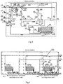
- the air-source heat pump underfloor-heating air conditioner system radiates heat to the indoor through underfloor-heating pipes laid under the ground to thereby improve the problem of non-uniform heating of the traditional multi-type air conditioner, and referring to Fig.1 , the air-source heat pump underfloor-heating air conditioner system includes an outdoor machine 101, an indoor machine 102, a refrigerant pipe 103, an electric three-way value 104, a fan coil 105, a three-position switch 106, an underfloor-heating pipe 107, a water pipe 108 and a controller 109.
- the outdoor machine 101 is connected with the indoor machine 102 through the refrigerant pipe 103; the fan coil 105 is connected in parallel with the underfloor-heating pipe 107 and connected with the indoor machine 102 through the water pipe 108; the three-position switch 106 is connected with the fan coil 105; the controller 109 is connected with the indoor machine 102; and the electric three-way value 104 is arranged among the indoor machine 102, the fan coil 105 and the underfloor-heating pipe 107.
- the outdoor machine 101 and the indoor machine 102 produce 7 ⁇ cold water
- the electric three-way value 104 controls the water pipe 108 directed to the underfloor-heating pipe 107 to be closed and the water pipe 108 directed to the fan coil 105 to be opened so that the cold water flows into the fan coil 105 through the water pipe 108 and is circled in the fan coil 105 through the water pump, and the three-position switch 106 controls the air speed of the fan coil 105, and cold air is transmitted to the indoor through the fan coil
- the outdoor machine 101 and the indoor machine 102 produce 50 ⁇ hot water
- the electric three-way value 104 controls the water pipe 108 directed to the underfloor-heating pipe 107 to be opened and the water pipe 108 directed to the fan coil 105 to be closed so that the hot water flows into the underfloor-heating pipe 107 through the water pipe 108 and is circled in the underfloor-heating pipe 107 through the water pump, and then heat is radiated by the underfloor-heating pipe to
- the indoor and outdoor machines during operation in the heating mode, produce the hot water at the fixed temperate 50 ⁇ for heating, and the hot water for heating is converted into water at 40 ⁇ after heat exchanging with indoor air in the underfloor-heating pipe and flows back into the indoor machine through the water pipe, and throughout the heating process, the indoor ambient temperature can only be adjusted roughly by the controller turning on and off the water pump but can not be controlled precisely in response to a demand of the users; and furthermore when there is a demand for heating in the building for a while, there is heating water in the underfloor-heating pipe, so it is necessary to prevent the underfloor-heating pipe from being frozen and broken at low temperature by powering the idle air-source heat pump underfloor-heating air conditioner system for normal operation of the indoor machine, thus resulting in a significant waste of power consumption.
- EP 0431491 A1 discloses a refrigeration cycle constitutes a closed cycle for circulating a refrigerant therein and includes at least a variable capacity compressor, an outdoor heat exchanger, an expansion valve, and an indoor heat exchanger.
- the indoor heat exchanger is provided with a room temperature sensor and an indoor fan.
- a floor heating panel is connected in parallel with the indoor heat exchanger.
- the panel is provided with a floor temperature sensor.
- a flow control valve is arranged in a refrigerant upstream side of the panel at a heating operation.
- a first controller controls the compressor, the fan, and the valve in a first state at the start of a heating operation to simultaneously start air heating by the indoor heat exchanger and floor heating by the panel.
- a second controller controls the compressor, the fan, and the valve in a second state when a detection output from the room temperature sensor reaches a preset valve, thereby maintaining a room temperature and increasing a floor temperature.
- a third controller controls at least one of the compressor and the valve in a third state when a detection output from the floor temperature sensor reaches a preset value, thereby maintaining the floor temperature and controls at least one of the compressor and then fan in a fourth state, thereby controlling the room temperature to a predetermined value
- An object of the invention is to provide an underfloor-heating multi-type air conditioner system so as to precisely control indoor temperature for heating while effectively lower power consumption.
- an underfloor-heating multi-type air conditioner system including: an outdoor machine, an indoor machine connected with the outdoor machine through a refrigerant pipe, and a controller connected respectively with the outdoor machine and the indoor machine through a shielded signal line, wherein the underfloor-heating multi-type air conditioner system further includes: a set of underfloor-heating pipes including a composite underfloor-heating pipe, a third cutoff valve, a third filter, a third electronic expanding valve, a fourth cutoff valve and an underfloor-heating pipe control board; the composite underfloor-heating pipe is connected with the outdoor machine through the refrigerant pipe and a manifold; the third cutoff valve, the third filter and the third electronic expanding valve are arranged in sequence in the inflow direction of a refrigerant on the refrigerant pipe connected with a refrigerant inflow end of the composite underfloor-heating pipe; the third electronic expanding valve is electrically connected with the underfloor-heating pipe control board; and the fourth cut
- the outdoor machine includes an outdoor machine control board unit, a refrigerant flow direction control unit, a refrigerant control unit, a valve control unit, an over-pressure protection unit and a filter protection unit
- the outdoor machine control board unit is configured to transmit a refrigerant flow direction control signal to the refrigerant flow direction control unit upon reception of a heating or refrigeration operation signal transmitted by the controller and to transmit a refrigerant control signal to the refrigerant control unit according to received indoor temperature and user-preset temperature transmitted by the controller
- the refrigerant flow direction control unit is configured to open the refrigerant pipe connected with the set of underfloor-heating pipes so that the refrigerant flows into the set of underfloor-heating pipes upon reception of the refrigerant flow direction control signal transmitted by the outdoor machine control board unit or to open the refrigerant pipe connected with the indoor machine so that the refrigerant flows into the indoor machine upon reception of the refrigeration operation signal transmitted by the outdoor machine control board unit
- the refrigerant control unit is configured to control
- the refrigerant flow direction control unit includes a first electromagnetic valve, a second electromagnetic valve, a third electromagnetic valve and a fourth electromagnetic valve, wherein the first electromagnetic valve is arranged on the refrigerant pipe connected with a refrigerant inflow end of the set of underfloor-heating pipes to control the refrigerant pipe connected with the refrigerant inflow end of the set of underfloor-heating pipes to be opened or closed; the second electromagnetic valve is arranged on the refrigerant pipe connected with a refrigerant outflow end of the indoor machine to control the refrigerant pipe connected with the refrigerant outflow end of the indoor machine to be opened or closed; the third electromagnetic valve is arranged on the refrigerant pipe connected with a refrigerant outflow end of the set of underfloor-heating pipes to control the refrigerant pipe connected with the refrigerant outflow end of the set of underfloor-heating pipes to be opened or closed; and the fourth electromagnetic valve is arranged on the refrigerant pipe connected with a refrigerant
- the controller transmits a refrigeration operation signal to the outdoor machine control board unit through the shielded signal line, so that the outdoor machine control board unit controls the second electromagnetic valve and the fourth electromagnetic valve in the refrigerant flow direction control unit to be opened and the first electromagnetic valve and the third electromagnetic valve to be closed.
- the controller transmits a heating operation signal to the outdoor machine control board unit through the shielded signal line, so that the outdoor machine control board unit controls the second electromagnetic valve and the fourth electromagnetic valve in the refrigerant flow direction control unit to be closed and the first electromagnetic valve and the third electromagnetic valve to be opened.
- the refrigerant control unit includes the compressor, a first heat exchanger, a first cold medium distributor, a first refreezer and an outdoor fan motor, wherein an input end of the compressor is connected with the filter protection unit, and an output end thereof is connected with the over-pressure protection unit; an input end of the first heat exchanger is connected with the valve control unit, and an output end thereof is connected with the first cold medium distributor; an output end of the first refreezer is connected with the valve control unit; and the outdoor fan motor is arranged proximate to the second heat exchanger.
- the refrigerant control unit further includes a first electronic expanding valve; and an input end of the first electronic expanding valve is connected with an output end of the first cold medium distributor, and an output end thereof is connected with an input end of the first refreezer, and the first electronic expanding valve is electrically connected with the outdoor machine control board.
- the indoor machine includes a second heat exchanger, a second filter, a second cold medium distributor, a second electronic expanding valve, an indoor fan motor, a first cutoff valve, a second cutoff valve and an indoor machine control board, wherein an input end of the second heat exchanger is connected with an output end of the second cold medium distributor, and an output end thereof is connected with an input end of the first cutoff valve; an input end of the second filter is connected with an output end of the second cutoff valve, and an output end thereof is connected with an input end of the second electronic expanding valve; an input end of the second cold medium distributor is connected with an output end of the second electronic expanding valve, and an output end thereof is connected with the input end of the second heat exchanger; an input end of the second electronic expanding valve is connected with an output end of the second filter, and an output end thereof is connected with the input end of the second cold medium distributor, and the second electronic expanding valve is connected with the indoor machine control board; the indoor fan motor is arranged proximate to the second heat exchanger; the input end of the first
- the composite underfloor-heating pipe is a copper pipe on the surface of which Polyethylene of raised temperature resistance (PE-RT), polyvinylchloride (PVC) or cross-linked polyethylene (PE-X) is coated.
- PE-RT Polyethylene of raised temperature resistance
- PVC polyvinylchloride
- PE-X cross-linked polyethylene
- the controller transmits the indoor temperature and the user-preset temperature data to the set of underfloor-heating pipes control board through the shielded signal line, and the set of underfloor-heating pipes control board controls the extent to which the third electronic expanding valve is opened according to the received signal to thereby adjust heating temperature.
- an underfloor-heating multi-type air conditioner system includes four components which are an outdoor machine, an indoor machine, a set of underfloor-heating pipes and a controller, where an electromagnetic valve in a refrigerant pipe directed to the set of underfloor-heating pipes in is closed, and an electromagnetic valve in a refrigerant pipe directed to the indoor machine in is opened so that a refrigerant is cycled only between the outdoor and indoor machines to perform a refrigeration function; whereas the electromagnetic valve in the refrigerant pipe directed to the set of underfloor-heating pipes in is opened, and the electromagnetic valve in the refrigerant pipe of the indoor machine in is closed so that the refrigerant is cycled only between the outdoor machine and the set of underfloor-heating pipes to perform a heating function; and electronic expanding valves are arranged respectively in the outdoor machine, the indoor machine and the set of underfloor-heating pipes, and during operation in a heating mode, a set of underfloor-heating pipes control board
- An embodiment of the invention provides an underfloor-heating multi-type air conditioner system including four components which are an outdoor machine, an indoor machine, a set of underfloor-heating pipes and a controller, where an electromagnetic valve in a refrigerant pipe directed to the set of underfloor-heating pipes in is closed, and an electromagnetic valve in a refrigerant pipe directed to the indoor machine in is opened so that a refrigerant is cycled only between the outdoor and indoor machines to perform a refrigeration function; whereas the electromagnetic valve in the refrigerant pipe directed to the set of underfloor-heating pipes in is opened, and the electromagnetic valve in the refrigerant pipe of the indoor machine in is closed so that the refrigerant is cycled only between the outdoor machine and the set of underfloor-heating pipes to perform a heating function; and electronic expanding valves are arranged respectively in the outdoor machine, the indoor machine and the set of underfloor-heating pipes, and during operation in a heating mode, a set of underfloor-heating pipes control board of the set of underfloor-heating pipes
- Fig.2 is a schematic structural diagram of an underfloor-heating multi-type air conditioner system according to an embodiment of the invention.
- the system includes an outdoor machine 100, an indoor machine 200, a set of underfloor-heating pipes 300, a controller 400, a refrigerant pipe 500, a manifold 600 and a shielded signal line 700, where:
- An output end of the outdoor machine 100 is connected with the refrigerant pipe 500;
- the outdoor machine 200 is connected with an input end of the refrigerant pipe 500;
- the set of underfloor-heating pipes 300 is connected with the input end of the refrigerant pipe 500;
- the controller 400 is connected respectively with an outdoor machine control board of the outdoor machine 100, an indoor machine control board of the indoor machine 200 and a set of underfloor-heating pipes control board of the set of underfloor-heating pipes 300 through the shielded signal line 700;
- the manifold 600 is connected with the output end of the refrigerant pipe 500;
- a second electromagnetic valve and a fourth electromagnetic valve are arranged on the refrigerant pipe 500 connected with the output end of the outdoor machine 100 and an input end of the indoor machine 200; and a first electromagnetic valve and a third electromagnetic valve are arranged on the refrigerant pipe 500 connected with the output end of the outdoor machine 100 and the set of underfloor-heating pipes; and
- the outdoor machine 100, the indoor machine 200 and the set of underfloor-heating pipes 300 are arranged respectively with electronic expanding valves.
- the controller 400 transmits a refrigeration operation signal to the control board of the outdoor machine 100 through the shielded signal line 700, and the outdoor machine control board of the outdoor machine 100 controls the second electromagnetic valve and the fourth electromagnetic valve in the outdoor machine 100 to be opened and the first electromagnetic valve and the third electromagnetic valve to be closed.
- the controller 400 furthers transmits acquired indoor temperature and received user-preset temperature data to the outdoor machine control board through the shielded signal line 700, so that the outdoor machine control board adjusts the operating frequency of a compressor and the rotation speed of an outdoor fan motor of the outdoor machine 100 according to the received data, and a refrigerant discharged by the outdoor machine 100 enters the indoor machine 200 through the refrigerant pipe 500 and the manifold 600, and cold air is transmitted by the indoor machine 200 to rooms; and the controller 400 transmits the acquired indoor temperature and the received user-preset temperature data to the indoor machine control board of the indoor machine 200 through the shielded signal line 700, so that the indoor machine control board controls the extent to which the electronic expanding valve of the indoor machine 200 is opened according to the received data so as to adjust the flow of the refrigerant to thereby precisely control the temperature inside the rooms.
- the controller 400 transmits a heating operation signal to the outdoor machine control board of the outdoor machine 100 through the shielded signal line 700, and the outdoor machine control board controls the second electromagnetic valve and the fourth electromagnetic valve to be closed and the first electromagnetic valve and the third electromagnetic valve to be opened.
- the controller 400 furthers transmits acquired indoor temperature and received user-preset temperature data to the outdoor machine control board through the shielded signal line 700, so that the outdoor machine control board adjusts the operating frequency of the compressor and the rotation speed of the outdoor fan motor of the outdoor machine 100 according to the received data, and the refrigerant discharged by the outdoor machine 100 enters the set of underfloor-heating pipes 300 through the refrigerant pipe 500 and the manifold 600, and heat is transmitted by the set of underfloor-heating pipes 300 to the rooms for heating; and the controller 400 transmits the acquired indoor temperature and the received user-preset temperature data to the set of underfloor-heating pipes control board of the set of underfloor-heating pipes 300 through the shielded signal line 700, so that the set of underfloor-heating pipes control board controls the extent to which the electronic expanding valve of the set of underfloor-heating pipes 300 is opened according to the received data so as to adjust the flow of the refrigerant to thereby precisely control the temperature inside the rooms.
- Fig.3 is a schematic structural diagram of the outdoor machine in the underfloor-heating multi-type air conditioner system according to the embodiment of the invention.
- the outdoor machine includes an outdoor machine control board unit, a refrigerant flow direction control unit, a refrigerant control unit, a valve control unit, an over-pressure protection unit and a filter protection unit, where:
- the outdoor machine control board unit is configured to transmit a refrigerant flow direction control signal to the refrigerant flow direction control unit upon reception of the heating or refrigeration operation signal transmitted by the controller 400 and to transmit a refrigerant control signal to the refrigerant control unit according to the received indoor temperature and user-preset temperature transmitted by the controller 400;
- the outdoor machine control board unit includes the outdoor machine control board 125;
- the refrigerant flow direction control unit is configured to open the refrigerant pipe 500 connected with the set of underfloor-heating pipes 300 so that the refrigerant flows into the set of underfloor-heating pipes 300 or to open the refrigerant pipe 500 connected with the indoor machine 200 so that the refrigerant flows into the indoor machine 200 upon reception of the refrigerant flow direction control signal transmitted by the outdoor machine control board 125;
- the refrigerant flow direction control unit particularly includes the first electromagnetic valve 113, the second electromagnetic valve 122, the third electromagnetic valve 123 and the fourth electromagnetic valve 124;
- the first electromagnetic valve 113 is arranged on the refrigerant pipe 500 connected with the refrigerant inflow end of the set of underfloor-heating pipes 300 to control the refrigerant pipe 500 connected with the refrigerant inflow end of the set of underfloor-heating pipes 300 to be opened or closed;
- the second electromagnetic valve 122 is arranged on the refrigerant pipe 500 connected with the refrigerant outflow end of the indoor machine 200 to control the refrigerant pipe 500 connected with the refrigerant outflow end of the indoor machine 200 to be opened or closed;
- the third electromagnetic valve 123 is arranged on the refrigerant pipe 500 connected with the refrigerant outflow end of the set of underfloor-heating pipes 300 to control the refrigerant pipe 500 connected with the refrigerant outflow end of the set of underfloor-heating pipes 300 to be opened or closed;
- the fourth electromagnetic valve 124 is arranged on the refrigerant pipe 500 connected with the refrigerant inflow end of the indoor machine 200 to control the refrigerant pipe 500 connected with the refrigerant inflow end of the indoor machine 200 to be opened or closed;
- the refrigerant control unit is configured to control the modality of the refrigerant and to control the flow of the refrigerant upon reception of the refrigerant control signal transmitted by the outdoor machine control board 125;
- the refrigerant control unit particularly includes the compressor 101, a first heat exchanger 102, a first cold medium distributor 108, a first electronic expanding valve 111, a first refreezer 119 and the outdoor fan motor 114;
- An input end of the compressor 101 is connected with an output end of a gas and liquid separator 104, and an output end thereof is connected with a high pressure protection switch 117;
- An input end of the first heat exchanger 102 is connected with a second end 109B of a four-way switching valve 109, and an output end thereof is connected with the first cold medium distributor 108;
- An input end of the first cold medium distributor 108 is connected with the output end of the first heat exchanger 102, and an output end thereof is connected with an input end of the first electronic expanding valve 111;
- the input end of the first electronic expanding valve 111 is connected with the output end of the first cold medium distributor 108, and an output end thereof is connected with an input end of the first refreezer 119, and the first electronic expanding valve 111 is electrically connected with the outdoor machine control board 125;
- An output end of the first refreezer 119 is connected with a second end 121B of a second three-way valve 121, and the input end thereof is connected with the first electronic expanding valve 111;
- a first end 121A of the second three-way valve 121 is connected with an output end of the third electromagnetic valve 123, the second end 121B of the second three-way valve 121 is connected with the output end of the first refreezer 119, and a third end 121C of the second three-way valve 121 is connected with an output end of an indoor machine liquid pipe cutoff valve 106;
- An input end of the third electromagnetic valve 123 is connected with a set of underfloor-heating pipes liquid pipe cutoff valve 115, and the output end of the third electromagnetic valve 123 is connected with the first end 121A of the second three-way valve 121;
- the outdoor fan motor 114 is arranged proximate to the first heat exchanger 102.
- the valve control unit is configured to control the valves in the outdoor machine through the outdoor control board 125, particularly the indoor machine liquid pipe cutoff valve 106, an indoor machine gas pipe cutoff valve 107, a four-way switching valve 109, a uni-way valve 112, the set of underfloor-heating pipes liquid pipe cutoff valve 115, a set of underfloor-heating pipes gas pipe cutoff valve 116, a first three-way valve 120 and a second three-way valve 121.
- the over-pressure protection unit is configured to detect the pressure of the refrigerant in the refrigerant pipe and to stop the compressor 101 from operating when the pressure exceeds a threshold, and particularly includes a high-pressure protection switch 117 and a cold medium pressure sensor 118;
- the filter protection unit is configured to filter out impurities in the refrigerant and to return lubricating oil separated from the refrigerant to the compressor, and particularly includes an oil separator 103, a gas and liquid separator 104, a first filter 105 and a capillary 110; and
- An gas inlet of the compressor 101 is connected with a gas discharge pipe of the gas and liquid separator 104, a gas outlet of the compressor 101 is connected with a gas inflow pipe of the oil separator 103, and the high-pressure protection switch 117 is arranged on a pipe connecting the compressor 101 with the oil separator 103; a gas discharge pipe of the oil separator 103 is connected with the uni-way valve 112, an oil return pipe of the oil separator 103 is connected with an input end of the first filter 105, an output end of the first filter 105 is connected with an input end of the capillary 110, and an output end of the capillary 110 is connected with a gas inflow pipe of the gas and liquid separator 104; the other end of the uni-way valve 112 is connected with a first end 109A of the four-way switching valve 109, and the first cold medium pressure sensor 118 is arranged on a pipe connecting the uni-way valve 112 with the first end of the four-way switching valve 109; the second end 109B
- the compressor 101 can be a general compressor, a fixed-frequency gas-supplementing enthalpy-gain compressor, a variable-frequency gas-supplementing enthalpy-gain compressor, a general variable-frequency compressor or a combination of a plurality of compressors.
- the high pressure protection switch 117 detects that the pressure of the refrigerant in the refrigerant pipe exceeds the threshold, the high pressure protection switch 117 is opened, and the compressor 101 is stopped from operating so that the refrigerant pipe can be prevented from being jammed and elements of the compressor 101 can be prevented from being wearing.
- Fig.4 is a schematic structural diagram of the indoor machine in the underfloor-heating multi-type air conditioner system according to the embodiment of the invention.
- the indoor machine includes a second heat exchanger 201, a second filter 202, a second cold medium distributor 203, a second electronic expanding valve 204, an indoor fan motor 205, a first cutoff valve 206, a second cutoff valve 207 and an indoor machine control board 208, where:
- An input end of the second heat exchanger 201 is connected with an output end of the second cold medium distributor 203, and an output end thereof is connected with an input end of the first cutoff valve 206; an input end of the second filter 202 is connected with an output end of the second cutoff valve 207, and an output end thereof is connected with an input end of the second electronic expanding valve 204; an input end of the second cold medium distributor 203 is connected with an output end of the second electronic expanding valve 204, and an output end thereof is connected with the input end of the second heat exchanger 201; an input end of the second electronic expanding valve 204 is connected with an output end of the second filter 202, and an output end thereof is connected with the input end of the second cold medium distributor 203, and the second electronic expanding valve 204 is connected with the indoor machine control board 208 through the shielded signal line 700; the indoor fan motor 205 is arranged proximate to the second heat exchanger 201 and composed of a direct-current motor or an alternating-current motor and a centrifugal fan or
- Fig.5 is a schematic structural diagram of the set of underfloor-heating pipes in the underfloor-heating multi-type air conditioner system according to the embodiment of the invention.
- the set of underfloor-heating pipes includes:
- the composite underfloor-heating pipe 301 is a copper pipe on the surface of which the material of Polyethylene of raised temperature resistance (PE-RT) with superior flexibility, high thermal conductivity, high-temperature resistance and pressure resistance is coated or polyvinylchloride (PVC), cross-linked polyethylene (PE-X) or other materials applicable to an underfloor-heating pipe can be coated.
- PE-RT Polyethylene of raised temperature resistance
- PVC polyvinylchloride
- PE-X cross-linked polyethylene
- An operating principle of the underfloor-heating multi-type air conditioner system according to the embodiment of the invention operating in the refrigeration mode is as follows: the controller 400 transmits the refrigeration operation signal to the outdoor machine control board 125 through the shielded signal line 700, so that the outdoor machine control board 125 controls the second electromagnetic valve 122 and the fourth electromagnetic valve 124 in the outdoor machine 100 to be opened and the first electromagnetic valve 113 and the third electromagnetic valve 123 of the outdoor machine to be closed; and in the meantime, the controller 400 further transmits the acquired indoor temperature and the received user-preset temperature data to the outdoor machine control board 125 and the underfloor-heating pipe control board 306 through the shielded signal line 700, so that the outdoor machine control board 125 adjusts the operating frequency of the compressor 101 and the rotation speed of the outdoor fan motor 114 of the outdoor machine 100 and controls the extent to which the first electromagnetic valve 111 is opened according to the received data, and the underfloor-heating pipe control board 306 controls the extent to which the third electromagnetic valve 303 is opened according to the received data.
- the refrigerant gas at high temperature and high pressure discharged through the gas outlet of the outdoor machine compressor 101 enters the oil separator 103, so that the impurities and the lubricating oil are separated by the oil separator 103 from the refrigerant gas, and the purified refrigerant gas is discharged from the gas discharge pipe of the oil separator 103 and enters the heat exchanger 102 of the outdoor machine through the first end 109A and the second end 109B of the four-way switching valve 109.
- the outdoor fan motor 114 draws outdoor air into the heat exchanger 102
- the refrigerant gas at high temperature and high pressure is condensed by the heat exchanger 102 of the outdoor machine to radiate heat and converted into liquid at intermediate temperature and high pressure
- the refrigerant liquid at intermediate temperature and high pressure flows into the cold media distributor 108 of the outdoor machine, has the amount of cycled refrigerant adjusted by the cold media distributor 108, and subsequently enters the refreezer 119 through the first electronic expanding valve 111 of the outdoor
- the refrigerant liquid at intermediate temperature and high pressure is converted by the refreezer 119 through expansion and a drop in pressure into the refrigerant liquid at low temperature and high pressure, and subsequently the refrigerant liquid passes in sequence through the second end 121B and the third end 121C of the second three-way valve 121, the fourth electromagnetic valve 124, the indoor machine liquid pipe cutoff valve 106, the second cutoff valve 207, the second filter 202 and the second electronic expanding valve 204 to be throttled and
- the refrigerant gas and liquid enters the cold media distributor 203 and has the amount of cycled refrigerant adjusted by the cold media distributor 203, and subsequently the two-phase mixture of the refrigerant gas and liquid at low temperature and low pressure enters the indoor machine heat exchanger 201 and absorbs heat by the indoor machine heat exchanger 201 to be converted into the refrigerant gas at low temperature and low pressure.
- the indoor air drawn by the indoor fan motor 205 into the heat exchanger 201 is cooled to drop in temperature and finally returned by the indoor fan motor 205 to the indoor through the air feeder, and the refrigerant gas at low temperature and low pressure enters the gas inflow pipe of the gas and liquid separator 104 through the first cutoff valve 206, the indoor machine gas pipe cutoff valve 107, the second electromagnetic valve 122, the second end 120B and the first end 120A of the first three-way valve 120, the fourth end 109D and the third end 109C of the four-way switching valve 109, and the cold media pressure sensor 118 in sequence; and in the meantime, a liquid mixture of the lubricating oil and the impurities discharged through the oil return pipe of the oil separator 103 has the impurities therein filtered out by the filter 105 and subsequently enters the gas inflow pipe of the gas and liquid separator 104 through the capillary 110, and the lubricating oil enters the compressor 101 through the gas inflow pipe of the compressor together
- An operating principle of the underfloor-heating multi-type air conditioner system according to the embodiment of the invention operating in the heating mode is as follows: the controller 400 transmits the heating operation signal to the outdoor machine control board 125 through the shielded signal line 700, so that the outdoor machine control board 125 controls the first electromagnetic valve 113 and the third electromagnetic valve 123 in the outdoor machine 100 to be opened and the second electromagnetic valve 122 and the fourth electromagnetic valve 124 of the outdoor machine to be closed; and in the meantime, the controller 400 further transmits the acquired indoor temperature and the received user-preset temperature data to the outdoor machine control board 125 and the underfloor-heating pipe control board 306 through the shielded signal line 700, so that the outdoor machine control board 125 adjusts the operating frequency of the compressor 101 and the rotation speed of the outdoor fan motor 114 of the outdoor machine 100 and controls the extent to which the first electromagnetic valve 111 is opened according to the received data, and the underfloor-heating pipe control board 306 controls the extent to which the third electromagnetic valve 303 is opened according to the received data.
- the refrigerant gas at high temperature and high pressure discharged through the gas outlet of the outdoor machine compressor 101 enters the oil separator 103, so that the impurities and the lubricating oil are separated by the oil separator 103 from the refrigerant gas, and the purified refrigerant gas is discharged from the gas discharge pipe of the oil separator 103 and enters the filter 302 through the first end 109A and the fourth end 109D of the four-way switching valve 109, the first end 120A and the third end 120C of the first three-way valve 120, the first electromagnetic valve 113, the set of underfloor-heating pipes gas pipe cutoff valve 116 and the third cutoff valve 304 in sequence.
- the impurities in the refrigerant gas at high temperature and high pressure are filtered out by the filter 302, and subsequently the refrigerant gas at high temperature and high pressure enters the composite underfloor-heating pipe 301 through the third electronic expanding valve 303, and since the composite underfloor-heating pipe 301 with high thermal conductivity radiates heat into the rooms, the refrigerant gas at high temperature and high pressure radiates heat to the rooms, and the amount of refrigerant entering the composite underfloor-heating pipe 301 is controlled by adjusting the extent to which the third electronic expanding valve 303 is opened so that the indoor temperature can be controlled precisely; and in the meantime, since there is no heating water in the composite underfloor-heating pipe 301, when the air conditioner system is unused for a while, the composite underfloor-heating pipe 301 will not be frozen and broken even if the system does not continue with being powered.
- the refrigerant gas at high temperature and high pressure is converted into the refrigerant liquid at intermediate temperature and high pressure and discharged through the discharge pipe of the composite underfloor-heating pipe 301 and subsequently enters the refreezer 119 through the fourth cutoff valve 305, the set of underfloor-heating pipes liquid pipe cutoff valve 115 and the third electromagnetic valve 123 in sequence, and the refrigerant liquid at intermediate temperature and high pressure is converted by the refreezer 119 into the refrigerant liquid at low temperature and high pressure.
- the refrigerant liquid is throttled by the first electronic expanding valve 111 and then converted into the refrigerant liquid at low temperature and low pressure and enters the cold media distributor 108 and has the amount of cycled refrigerant adjusted by the cold media distributor 108 and subsequently enter the heat exchanger 102 of the outdoor machine and absorbs heat by the heat exchanger 102 of the outdoor machine to be converted into the refrigerant gas at low temperature and low voltage, and the refrigerant gas at low temperature and low voltage enters the gas inflow pipe of the gas and liquid separator 104 through the second end 109B and the third end 109C of the four-way switching valve 109; and in the meantime, a liquid mixture of the lubricating oil and the impurities discharged through the oil return pipe of the oil separator 103 has the impurities therein filtered out by the filter 105 and subsequently enters the gas inflow pipe of the gas and liquid separator 104 through the capillary 110, and the lubricating oil that can not be gasified enters the compressor 101
Landscapes
- Engineering & Computer Science (AREA)
- Mechanical Engineering (AREA)
- General Engineering & Computer Science (AREA)
- Physics & Mathematics (AREA)
- Thermal Sciences (AREA)
- Chemical & Material Sciences (AREA)
- Combustion & Propulsion (AREA)
- Air Conditioning Control Device (AREA)
- Other Air-Conditioning Systems (AREA)
Description
- The present invention relates to the field of air conditioners and particularly to an underfloor-heating multi-type air conditioner system.
- A multi-type air conditioner system is generally applicable to clustered buildings and can provide users with comfortable indoor living and working environments despite an hostile outdoor ambient. During operation in a heating mode, the traditional multi-type air conditioner system transmits hot air to the indoor through vents arranged on a ceiling, but the hot air tends to be concentrated proximate to the ceiling so that the indoor temperature drops stepwise from the top down, and the users feel hot at their heads and cold at their feet; and also the multi-type air conditioner system raises the air pressure and the air transmission speed of a fan so that the overall indoor temperature reaches a preset value, and in this meantime the indoor noise will become more apparent, thus degrading the comfortability of the users.
- At present a air-source heat pump underfloor-heating air conditioner system radiates heat to the indoor through underfloor-heating pipes laid under the ground to thereby improve the problem of non-uniform heating of the traditional multi-type air conditioner, and referring to
Fig.1 , the air-source heat pump underfloor-heating air conditioner system includes anoutdoor machine 101, anindoor machine 102, arefrigerant pipe 103, an electric three-way value 104, afan coil 105, a three-position switch 106, an underfloor-heating pipe 107, awater pipe 108 and acontroller 109. Theoutdoor machine 101 is connected with theindoor machine 102 through therefrigerant pipe 103; thefan coil 105 is connected in parallel with the underfloor-heating pipe 107 and connected with theindoor machine 102 through thewater pipe 108; the three-position switch 106 is connected with thefan coil 105; thecontroller 109 is connected with theindoor machine 102; and the electric three-way value 104 is arranged among theindoor machine 102, thefan coil 105 and the underfloor-heating pipe 107. - For refrigeration in summer, the
outdoor machine 101 and theindoor machine 102 produce 7□ cold water, and the electric three-way value 104 controls thewater pipe 108 directed to the underfloor-heating pipe 107 to be closed and thewater pipe 108 directed to thefan coil 105 to be opened so that the cold water flows into thefan coil 105 through thewater pipe 108 and is circled in thefan coil 105 through the water pump, and the three-position switch 106 controls the air speed of thefan coil 105, and cold air is transmitted to the indoor through the fan coil; and for heating in winter, theoutdoor machine 101 and theindoor machine 102 produce 50□ hot water, and the electric three-way value 104 controls thewater pipe 108 directed to the underfloor-heating pipe 107 to be opened and thewater pipe 108 directed to thefan coil 105 to be closed so that the hot water flows into the underfloor-heating pipe 107 through thewater pipe 108 and is circled in the underfloor-heating pipe 107 through the water pump, and then heat is radiated by the underfloor-heating pipe to the indoor. - As can be apparent from the technical solution above, with the existing air-source heat pump underfloor-heating air conditioner system, during operation in the heating mode, the indoor and outdoor machines produce the hot water at the fixed temperate 50□ for heating, and the hot water for heating is converted into water at 40 □ after heat exchanging with indoor air in the underfloor-heating pipe and flows back into the indoor machine through the water pipe, and throughout the heating process, the indoor ambient temperature can only be adjusted roughly by the controller turning on and off the water pump but can not be controlled precisely in response to a demand of the users; and furthermore when there is a demand for heating in the building for a while, there is heating water in the underfloor-heating pipe, so it is necessary to prevent the underfloor-heating pipe from being frozen and broken at low temperature by powering the idle air-source heat pump underfloor-heating air conditioner system for normal operation of the indoor machine, thus resulting in a significant waste of power consumption.
-
EP 0431491 A1 discloses a refrigeration cycle constitutes a closed cycle for circulating a refrigerant therein and includes at least a variable capacity compressor, an outdoor heat exchanger, an expansion valve, and an indoor heat exchanger. The indoor heat exchanger is provided with a room temperature sensor and an indoor fan. A floor heating panel is connected in parallel with the indoor heat exchanger. The panel is provided with a floor temperature sensor. A flow control valve is arranged in a refrigerant upstream side of the panel at a heating operation. A first controller controls the compressor, the fan, and the valve in a first state at the start of a heating operation to simultaneously start air heating by the indoor heat exchanger and floor heating by the panel. A second controller controls the compressor, the fan, and the valve in a second state when a detection output from the room temperature sensor reaches a preset valve, thereby maintaining a room temperature and increasing a floor temperature. A third controller controls at least one of the compressor and the valve in a third state when a detection output from the floor temperature sensor reaches a preset value, thereby maintaining the floor temperature and controls at least one of the compressor and then fan in a fourth state, thereby controlling the room temperature to a predetermined value, - An object of the invention is to provide an underfloor-heating multi-type air conditioner system so as to precisely control indoor temperature for heating while effectively lower power consumption.
- According to an aspect of the invention, there is provided an underfloor-heating multi-type air conditioner system including: an outdoor machine, an indoor machine connected with the outdoor machine through a refrigerant pipe, and a controller connected respectively with the outdoor machine and the indoor machine through a shielded signal line, wherein the underfloor-heating multi-type air conditioner system further includes: a set of underfloor-heating pipes including a composite underfloor-heating pipe, a third cutoff valve, a third filter, a third electronic expanding valve, a fourth cutoff valve and an underfloor-heating pipe control board; the composite underfloor-heating pipe is connected with the outdoor machine through the refrigerant pipe and a manifold; the third cutoff valve, the third filter and the third electronic expanding valve are arranged in sequence in the inflow direction of a refrigerant on the refrigerant pipe connected with a refrigerant inflow end of the composite underfloor-heating pipe; the third electronic expanding valve is electrically connected with the underfloor-heating pipe control board; and the fourth cutoff valve is arranged on the refrigerant pipe connected with a refrigerant outflow end of the composite underfloor-heating pipe.
- Preferably the outdoor machine includes an outdoor machine control board unit, a refrigerant flow direction control unit, a refrigerant control unit, a valve control unit, an over-pressure protection unit and a filter protection unit, wherein the outdoor machine control board unit is configured to transmit a refrigerant flow direction control signal to the refrigerant flow direction control unit upon reception of a heating or refrigeration operation signal transmitted by the controller and to transmit a refrigerant control signal to the refrigerant control unit according to received indoor temperature and user-preset temperature transmitted by the controller; the refrigerant flow direction control unit is configured to open the refrigerant pipe connected with the set of underfloor-heating pipes so that the refrigerant flows into the set of underfloor-heating pipes upon reception of the refrigerant flow direction control signal transmitted by the outdoor machine control board unit or to open the refrigerant pipe connected with the indoor machine so that the refrigerant flows into the indoor machine upon reception of the refrigeration operation signal transmitted by the outdoor machine control board unit; the refrigerant control unit is configured to control the modality of the refrigerant and to control the flow of the refrigerant upon reception of the refrigerant control signal transmitted by the outdoor machine control board; the valve control unit is configured to control the valves in the outdoor machine through the outdoor control board unit; the over-pressure protection unit is configured to detect the pressure of the refrigerant in the refrigerant pipe and to stop a compressor from operating when the pressure exceeds a threshold; and the filter protection unit is configured to filter out impurities in the refrigerant and to return lubricating oil separated from the refrigerant to the compressor.
- Preferably the refrigerant flow direction control unit includes a first electromagnetic valve, a second electromagnetic valve, a third electromagnetic valve and a fourth electromagnetic valve, wherein the first electromagnetic valve is arranged on the refrigerant pipe connected with a refrigerant inflow end of the set of underfloor-heating pipes to control the refrigerant pipe connected with the refrigerant inflow end of the set of underfloor-heating pipes to be opened or closed; the second electromagnetic valve is arranged on the refrigerant pipe connected with a refrigerant outflow end of the indoor machine to control the refrigerant pipe connected with the refrigerant outflow end of the indoor machine to be opened or closed; the third electromagnetic valve is arranged on the refrigerant pipe connected with a refrigerant outflow end of the set of underfloor-heating pipes to control the refrigerant pipe connected with the refrigerant outflow end of the set of underfloor-heating pipes to be opened or closed; and the fourth electromagnetic valve is arranged on the refrigerant pipe connected with a refrigerant inflow end of the indoor machine to control the refrigerant pipe connected with the refrigerant inflow end of the indoor machine to be opened or closed.
- Preferably when the underfloor-heating multi-type air conditioner system operates in a refrigeration mode, the controller transmits a refrigeration operation signal to the outdoor machine control board unit through the shielded signal line, so that the outdoor machine control board unit controls the second electromagnetic valve and the fourth electromagnetic valve in the refrigerant flow direction control unit to be opened and the first electromagnetic valve and the third electromagnetic valve to be closed.
- Preferably when the underfloor-heating multi-type air conditioner system operates in a heating mode, the controller transmits a heating operation signal to the outdoor machine control board unit through the shielded signal line, so that the outdoor machine control board unit controls the second electromagnetic valve and the fourth electromagnetic valve in the refrigerant flow direction control unit to be closed and the first electromagnetic valve and the third electromagnetic valve to be opened.
- Preferably the refrigerant control unit includes the compressor, a first heat exchanger, a first cold medium distributor, a first refreezer and an outdoor fan motor, wherein an input end of the compressor is connected with the filter protection unit, and an output end thereof is connected with the over-pressure protection unit; an input end of the first heat exchanger is connected with the valve control unit, and an output end thereof is connected with the first cold medium distributor; an output end of the first refreezer is connected with the valve control unit; and the outdoor fan motor is arranged proximate to the second heat exchanger.
- Preferably the refrigerant control unit further includes a first electronic expanding valve; and an input end of the first electronic expanding valve is connected with an output end of the first cold medium distributor, and an output end thereof is connected with an input end of the first refreezer, and the first electronic expanding valve is electrically connected with the outdoor machine control board.
- Preferably the indoor machine includes a second heat exchanger, a second filter, a second cold medium distributor, a second electronic expanding valve, an indoor fan motor, a first cutoff valve, a second cutoff valve and an indoor machine control board, wherein an input end of the second heat exchanger is connected with an output end of the second cold medium distributor, and an output end thereof is connected with an input end of the first cutoff valve; an input end of the second filter is connected with an output end of the second cutoff valve, and an output end thereof is connected with an input end of the second electronic expanding valve; an input end of the second cold medium distributor is connected with an output end of the second electronic expanding valve, and an output end thereof is connected with the input end of the second heat exchanger; an input end of the second electronic expanding valve is connected with an output end of the second filter, and an output end thereof is connected with the input end of the second cold medium distributor, and the second electronic expanding valve is connected with the indoor machine control board; the indoor fan motor is arranged proximate to the second heat exchanger; the input end of the first cutoff valve is connected with an output end of the second heat exchanger, and the output end thereof is connected with an input end of the manifold; and an input end of the second cutoff valve is connected with an input end of the refrigerant pipe, and the output end thereof is connected with the input end of the manifold.
- Preferably the composite underfloor-heating pipe is a copper pipe on the surface of which Polyethylene of raised temperature resistance (PE-RT), polyvinylchloride (PVC) or cross-linked polyethylene (PE-X) is coated.
- Preferably when the underfloor-heating multi-type air conditioner system operates in a heating mode, the controller transmits the indoor temperature and the user-preset temperature data to the set of underfloor-heating pipes control board through the shielded signal line, and the set of underfloor-heating pipes control board controls the extent to which the third electronic expanding valve is opened according to the received signal to thereby adjust heating temperature.
- As can be apparent from the technical solution above, an underfloor-heating multi-type air conditioner system according to an embodiment of the invention includes four components which are an outdoor machine, an indoor machine, a set of underfloor-heating pipes and a controller, where an electromagnetic valve in a refrigerant pipe directed to the set of underfloor-heating pipes in is closed, and an electromagnetic valve in a refrigerant pipe directed to the indoor machine in is opened so that a refrigerant is cycled only between the outdoor and indoor machines to perform a refrigeration function; whereas the electromagnetic valve in the refrigerant pipe directed to the set of underfloor-heating pipes in is opened, and the electromagnetic valve in the refrigerant pipe of the indoor machine in is closed so that the refrigerant is cycled only between the outdoor machine and the set of underfloor-heating pipes to perform a heating function; and electronic expanding valves are arranged respectively in the outdoor machine, the indoor machine and the set of underfloor-heating pipes, and during operation in a heating mode, a set of underfloor-heating pipes control board of the set of underfloor-heating pipes controls the extent to which the electronic expanding valve in the set of underfloor-heating pipes is opened so as to adjust the flow of the refrigerant so that indoor temperature in the heating mode can be controlled precisely. Since there is no hot water for heating in the set of underfloor-heating pipes, the air conditioner system can be idle without any operation for preventing the set of underfloor-heating pipes from being frozen and broken at low temperature, thus improving the reliability while saving power consumption.
- In order to describe technical solutions of the embodiments of the invention or in the prior art more clearly, the drawings to be used in the description of the embodiments or the prior art will be introduced below in brief. Apparently the drawings described below are merely some embodiments of the invention
-
Fig.1 is a schematic structural diagram of the air-source heat pump underfloor-heating air conditioner system in the art; -
Fig.2 is a schematic structural diagram of an underfloor-heating multi-type air conditioner system according to an embodiment of the invention; -
Fig.3 is a schematic structural diagram of an outdoor machine in the underfloor-heating multi-type air conditioner system according to the embodiment of the invention; -
Fig.4 is a schematic structural diagram of an indoor machine in the underfloor-heating multi-type air conditioner system according to the embodiment of the invention; and -
Fig.5 is a schematic structural diagram of a set of underfloor-heating pipes in the underfloor-heating multi-type air conditioner system according to the embodiment of the invention. - In order to make the objects, technical solutions and advantages of the invention more apparent, the invention will be described below in further details with reference to the drawings and preferred embodiments thereof. However it shall be noted that numerous details listed in the description are merely intended to facilitate thorough understanding by readers of one or more aspects of the invention, and these aspects of the invention can also be implemented without these particular details.
- An embodiment of the invention provides an underfloor-heating multi-type air conditioner system including four components which are an outdoor machine, an indoor machine, a set of underfloor-heating pipes and a controller, where an electromagnetic valve in a refrigerant pipe directed to the set of underfloor-heating pipes in is closed, and an electromagnetic valve in a refrigerant pipe directed to the indoor machine in is opened so that a refrigerant is cycled only between the outdoor and indoor machines to perform a refrigeration function; whereas the electromagnetic valve in the refrigerant pipe directed to the set of underfloor-heating pipes in is opened, and the electromagnetic valve in the refrigerant pipe of the indoor machine in is closed so that the refrigerant is cycled only between the outdoor machine and the set of underfloor-heating pipes to perform a heating function; and electronic expanding valves are arranged respectively in the outdoor machine, the indoor machine and the set of underfloor-heating pipes, and during operation in a heating mode, a set of underfloor-heating pipes control board of the set of underfloor-heating pipes controls the extent to which the electronic expanding valve in the set of underfloor-heating pipes is opened so as to adjust the flow of the refrigerant so that indoor temperature in the heating mode can be controlled precisely. Since there is no hot water for heating in the set of underfloor-heating pipes, the air conditioner system can be idle without any operation for preventing the set of underfloor-heating pipes from being frozen and broken at low temperature, thus improving the reliability while saving power consumption.
-
Fig.2 is a schematic structural diagram of an underfloor-heating multi-type air conditioner system according to an embodiment of the invention. Referring toFig.2 , the system includes anoutdoor machine 100, anindoor machine 200, a set of underfloor-heating pipes 300, acontroller 400, arefrigerant pipe 500, amanifold 600 and a shieldedsignal line 700, where: - An output end of the
outdoor machine 100 is connected with therefrigerant pipe 500; - The
outdoor machine 200 is connected with an input end of therefrigerant pipe 500; - The set of underfloor-
heating pipes 300 is connected with the input end of therefrigerant pipe 500; - The
controller 400 is connected respectively with an outdoor machine control board of theoutdoor machine 100, an indoor machine control board of theindoor machine 200 and a set of underfloor-heating pipes control board of the set of underfloor-heating pipes 300 through the shieldedsignal line 700; - The
manifold 600 is connected with the output end of therefrigerant pipe 500; - A second electromagnetic valve and a fourth electromagnetic valve are arranged on the
refrigerant pipe 500 connected with the output end of theoutdoor machine 100 and an input end of theindoor machine 200; and a first electromagnetic valve and a third electromagnetic valve are arranged on therefrigerant pipe 500 connected with the output end of theoutdoor machine 100 and the set of underfloor-heating pipes; and - The
outdoor machine 100, theindoor machine 200 and the set of underfloor-heating pipes 300 are arranged respectively with electronic expanding valves. - In the embodiment of the invention, when the underfloor-heating multi-type air conditioner system operates in a refrigeration mode, the
controller 400 transmits a refrigeration operation signal to the control board of theoutdoor machine 100 through the shieldedsignal line 700, and the outdoor machine control board of theoutdoor machine 100 controls the second electromagnetic valve and the fourth electromagnetic valve in theoutdoor machine 100 to be opened and the first electromagnetic valve and the third electromagnetic valve to be closed. In the meantime, thecontroller 400 furthers transmits acquired indoor temperature and received user-preset temperature data to the outdoor machine control board through the shieldedsignal line 700, so that the outdoor machine control board adjusts the operating frequency of a compressor and the rotation speed of an outdoor fan motor of theoutdoor machine 100 according to the received data, and a refrigerant discharged by theoutdoor machine 100 enters theindoor machine 200 through therefrigerant pipe 500 and themanifold 600, and cold air is transmitted by theindoor machine 200 to rooms; and thecontroller 400 transmits the acquired indoor temperature and the received user-preset temperature data to the indoor machine control board of theindoor machine 200 through the shieldedsignal line 700, so that the indoor machine control board controls the extent to which the electronic expanding valve of theindoor machine 200 is opened according to the received data so as to adjust the flow of the refrigerant to thereby precisely control the temperature inside the rooms. - When the underfloor-heating multi-type air conditioner system operates in a heating mode, the
controller 400 transmits a heating operation signal to the outdoor machine control board of theoutdoor machine 100 through the shieldedsignal line 700, and the outdoor machine control board controls the second electromagnetic valve and the fourth electromagnetic valve to be closed and the first electromagnetic valve and the third electromagnetic valve to be opened. In the meantime, thecontroller 400 furthers transmits acquired indoor temperature and received user-preset temperature data to the outdoor machine control board through the shieldedsignal line 700, so that the outdoor machine control board adjusts the operating frequency of the compressor and the rotation speed of the outdoor fan motor of theoutdoor machine 100 according to the received data, and the refrigerant discharged by theoutdoor machine 100 enters the set of underfloor-heating pipes 300 through therefrigerant pipe 500 and themanifold 600, and heat is transmitted by the set of underfloor-heating pipes 300 to the rooms for heating; and thecontroller 400 transmits the acquired indoor temperature and the received user-preset temperature data to the set of underfloor-heating pipes control board of the set of underfloor-heating pipes 300 through the shieldedsignal line 700, so that the set of underfloor-heating pipes control board controls the extent to which the electronic expanding valve of the set of underfloor-heating pipes 300 is opened according to the received data so as to adjust the flow of the refrigerant to thereby precisely control the temperature inside the rooms. -
Fig.3 is a schematic structural diagram of the outdoor machine in the underfloor-heating multi-type air conditioner system according to the embodiment of the invention. Referring toFig.3 , the outdoor machine includes an outdoor machine control board unit, a refrigerant flow direction control unit, a refrigerant control unit, a valve control unit, an over-pressure protection unit and a filter protection unit, where: - The outdoor machine control board unit is configured to transmit a refrigerant flow direction control signal to the refrigerant flow direction control unit upon reception of the heating or refrigeration operation signal transmitted by the
controller 400 and to transmit a refrigerant control signal to the refrigerant control unit according to the received indoor temperature and user-preset temperature transmitted by thecontroller 400; - The outdoor machine control board unit includes the outdoor
machine control board 125; - The refrigerant flow direction control unit is configured to open the
refrigerant pipe 500 connected with the set of underfloor-heating pipes 300 so that the refrigerant flows into the set of underfloor-heating pipes 300 or to open therefrigerant pipe 500 connected with theindoor machine 200 so that the refrigerant flows into theindoor machine 200 upon reception of the refrigerant flow direction control signal transmitted by the outdoormachine control board 125; - The refrigerant flow direction control unit particularly includes the first
electromagnetic valve 113, the secondelectromagnetic valve 122, the thirdelectromagnetic valve 123 and the fourthelectromagnetic valve 124; - The first
electromagnetic valve 113 is arranged on therefrigerant pipe 500 connected with the refrigerant inflow end of the set of underfloor-heating pipes 300 to control therefrigerant pipe 500 connected with the refrigerant inflow end of the set of underfloor-heating pipes 300 to be opened or closed; - The second
electromagnetic valve 122 is arranged on therefrigerant pipe 500 connected with the refrigerant outflow end of theindoor machine 200 to control therefrigerant pipe 500 connected with the refrigerant outflow end of theindoor machine 200 to be opened or closed; - The third
electromagnetic valve 123 is arranged on therefrigerant pipe 500 connected with the refrigerant outflow end of the set of underfloor-heating pipes 300 to control therefrigerant pipe 500 connected with the refrigerant outflow end of the set of underfloor-heating pipes 300 to be opened or closed; - The fourth
electromagnetic valve 124 is arranged on therefrigerant pipe 500 connected with the refrigerant inflow end of theindoor machine 200 to control therefrigerant pipe 500 connected with the refrigerant inflow end of theindoor machine 200 to be opened or closed; - The refrigerant control unit is configured to control the modality of the refrigerant and to control the flow of the refrigerant upon reception of the refrigerant control signal transmitted by the outdoor
machine control board 125; - The refrigerant control unit particularly includes the
compressor 101, afirst heat exchanger 102, a first coldmedium distributor 108, a first electronic expandingvalve 111, afirst refreezer 119 and theoutdoor fan motor 114; - An input end of the
compressor 101 is connected with an output end of a gas andliquid separator 104, and an output end thereof is connected with a high pressure protection switch 117; - An input end of the
first heat exchanger 102 is connected with asecond end 109B of a four-way switching valve 109, and an output end thereof is connected with the first coldmedium distributor 108; - An input end of the first cold
medium distributor 108 is connected with the output end of thefirst heat exchanger 102, and an output end thereof is connected with an input end of the first electronic expandingvalve 111; - The input end of the first electronic expanding
valve 111 is connected with the output end of the first coldmedium distributor 108, and an output end thereof is connected with an input end of thefirst refreezer 119, and the first electronic expandingvalve 111 is electrically connected with the outdoormachine control board 125; - An output end of the
first refreezer 119 is connected with asecond end 121B of a second three-way valve 121, and the input end thereof is connected with the first electronic expandingvalve 111; - A
first end 121A of the second three-way valve 121 is connected with an output end of the thirdelectromagnetic valve 123, thesecond end 121B of the second three-way valve 121 is connected with the output end of thefirst refreezer 119, and athird end 121C of the second three-way valve 121 is connected with an output end of an indoor machine liquidpipe cutoff valve 106; - An input end of the third
electromagnetic valve 123 is connected with a set of underfloor-heating pipes liquidpipe cutoff valve 115, and the output end of the thirdelectromagnetic valve 123 is connected with thefirst end 121A of the second three-way valve 121; - The
outdoor fan motor 114 is arranged proximate to thefirst heat exchanger 102. - The valve control unit is configured to control the valves in the outdoor machine through the
outdoor control board 125, particularly the indoor machine liquidpipe cutoff valve 106, an indoor machine gaspipe cutoff valve 107, a four-way switching valve 109, auni-way valve 112, the set of underfloor-heating pipes liquidpipe cutoff valve 115, a set of underfloor-heating pipes gaspipe cutoff valve 116, a first three-way valve 120 and a second three-way valve 121. - The over-pressure protection unit is configured to detect the pressure of the refrigerant in the refrigerant pipe and to stop the
compressor 101 from operating when the pressure exceeds a threshold, and particularly includes a high-pressure protection switch 117 and a coldmedium pressure sensor 118; - The filter protection unit is configured to filter out impurities in the refrigerant and to return lubricating oil separated from the refrigerant to the compressor, and particularly includes an
oil separator 103, a gas andliquid separator 104, afirst filter 105 and a capillary 110; and - An gas inlet of the compressor 101 is connected with a gas discharge pipe of the gas and liquid separator 104, a gas outlet of the compressor 101 is connected with a gas inflow pipe of the oil separator 103, and the high-pressure protection switch 117 is arranged on a pipe connecting the compressor 101 with the oil separator 103; a gas discharge pipe of the oil separator 103 is connected with the uni-way valve 112, an oil return pipe of the oil separator 103 is connected with an input end of the first filter 105, an output end of the first filter 105 is connected with an input end of the capillary 110, and an output end of the capillary 110 is connected with a gas inflow pipe of the gas and liquid separator 104; the other end of the uni-way valve 112 is connected with a first end 109A of the four-way switching valve 109, and the first cold medium pressure sensor 118 is arranged on a pipe connecting the uni-way valve 112 with the first end of the four-way switching valve 109; the second end 109B of the four-way switching valve 109 is connected with the first heat exchanger 102, a third end 109C of the four-way switching valve 109 is connected with the gas and liquid separator 104, and a fourth end 109D of the four-way switching valve 109 is connected with a first end 120A of the first three-way valve 120; a second end 120B of the first three-way valve 120 is connected with the second electromagnetic valve 122, and a third end 120C of the first three-way valve 120 is connected with the first electromagnetic valve 113; the other end of the electromagnetic valve 113 is connected with the set of underfloor-heating pipes gas pipe cutoff valve 116; the other end of the second electromagnetic valve 122 is connected with the indoor machine gas pipe cutoff valve 107; an output end of the heat exchanger 102 is connected with the input end of the first cold medium distributor 108, the output end of the first cold medium distributor 108 is connected with the first electronic expanding valve 111, the other end of the first electronic expanding valve 111 is connected with the input end of the first refreezer 119, and the output end of the first refreezer 119 is connected with the second end 121B of the second three-way valve 121; the first end 121A of the second three-way valve 121 is connected with the third electromagnetic valve 123, and the third end 121C of the second three-way valve 121 is connected with the fourth electromagnetic valve 124; the other end of the third electromagnetic valve 123 is connected with the set of underfloor-heating pipes liquid pipe cutoff valve 115; and the other end of the fourth electromagnetic valve 124 is connected with the indoor machine liquid pipe cutoff valve 106, the outdoor fan motor 114 is arranged proximate to the first heat exchanger 102 and composed of a direct-current motor or an alternating-current motor and an axis-current fan to draw outdoor air into the first heat exchanger 102.
- In the embodiment of the invention, the
compressor 101 can be a general compressor, a fixed-frequency gas-supplementing enthalpy-gain compressor, a variable-frequency gas-supplementing enthalpy-gain compressor, a general variable-frequency compressor or a combination of a plurality of compressors. - In a practical application, when the high pressure protection switch 117 detects that the pressure of the refrigerant in the refrigerant pipe exceeds the threshold, the high pressure protection switch 117 is opened, and the
compressor 101 is stopped from operating so that the refrigerant pipe can be prevented from being jammed and elements of thecompressor 101 can be prevented from being wearing. -
Fig.4 is a schematic structural diagram of the indoor machine in the underfloor-heating multi-type air conditioner system according to the embodiment of the invention. Referring toFig.4 , the indoor machine includes asecond heat exchanger 201, asecond filter 202, a second coldmedium distributor 203, a second electronic expandingvalve 204, anindoor fan motor 205, afirst cutoff valve 206, asecond cutoff valve 207 and an indoormachine control board 208, where: - An input end of the second heat exchanger 201 is connected with an output end of the second cold medium distributor 203, and an output end thereof is connected with an input end of the first cutoff valve 206; an input end of the second filter 202 is connected with an output end of the second cutoff valve 207, and an output end thereof is connected with an input end of the second electronic expanding valve 204; an input end of the second cold medium distributor 203 is connected with an output end of the second electronic expanding valve 204, and an output end thereof is connected with the input end of the second heat exchanger 201; an input end of the second electronic expanding valve 204 is connected with an output end of the second filter 202, and an output end thereof is connected with the input end of the second cold medium distributor 203, and the second electronic expanding valve 204 is connected with the indoor machine control board 208 through the shielded signal line 700; the indoor fan motor 205 is arranged proximate to the second heat exchanger 201 and composed of a direct-current motor or an alternating-current motor and a centrifugal fan or a cross-flow fan to draw indoor air into the second heat exchanger 201; the input end of the first cutoff valve 206 is connected with the output end of the second heat exchanger 201, and the output end thereof is connected with an input end of the manifold 600; and an input end of the second cutoff valve 207 is connected with the input end of the refrigerant pipe 500, and the output end thereof is connected with the input end of the manifold 600.
-
Fig.5 is a schematic structural diagram of the set of underfloor-heating pipes in the underfloor-heating multi-type air conditioner system according to the embodiment of the invention. Referring toFig.5 , the set of underfloor-heating pipes includes: - A composite underfloor-
heating pipe 301, athird filter 302, a third electronic expandingvalve 303, athird cutoff valve 304, afourth cutoff valve 305 and an underfloor-heatingpipe control board 306, where: - The composite underfloor-
heating pipe 301 is connected with theoutdoor machine 100 through therefrigerant pipe 500 and the manifold 600; - The
third cutoff valve 304, thethird filter 302 and the third electronic expandingvalve 303 are arranged in sequence in the inflow direction of the refrigerant on therefrigerant pipe 500 connected with a refrigerant inflow end of the composite underfloor-heating pipe 301; - The third electronic expanding
valve 303 is electrically connected with the underfloor-heatingpipe control board 306; and - The
fourth cutoff valve 305 is arranged on therefrigerant pipe 500 connected with a refrigerant outflow end of the composite underfloor-heating pipe 301. - In the embodiment of the invention, the composite underfloor-
heating pipe 301 is a copper pipe on the surface of which the material of Polyethylene of raised temperature resistance (PE-RT) with superior flexibility, high thermal conductivity, high-temperature resistance and pressure resistance is coated or polyvinylchloride (PVC), cross-linked polyethylene (PE-X) or other materials applicable to an underfloor-heating pipe can be coated. - An operating principle of the underfloor-heating multi-type air conditioner system according to the embodiment of the invention operating in the refrigeration mode is as follows: the
controller 400 transmits the refrigeration operation signal to the outdoormachine control board 125 through the shieldedsignal line 700, so that the outdoormachine control board 125 controls the secondelectromagnetic valve 122 and the fourthelectromagnetic valve 124 in theoutdoor machine 100 to be opened and the firstelectromagnetic valve 113 and the thirdelectromagnetic valve 123 of the outdoor machine to be closed; and in the meantime, thecontroller 400 further transmits the acquired indoor temperature and the received user-preset temperature data to the outdoormachine control board 125 and the underfloor-heatingpipe control board 306 through the shieldedsignal line 700, so that the outdoormachine control board 125 adjusts the operating frequency of thecompressor 101 and the rotation speed of theoutdoor fan motor 114 of theoutdoor machine 100 and controls the extent to which the firstelectromagnetic valve 111 is opened according to the received data, and the underfloor-heatingpipe control board 306 controls the extent to which the thirdelectromagnetic valve 303 is opened according to the received data. - The refrigerant gas at high temperature and high pressure discharged through the gas outlet of the
outdoor machine compressor 101 enters theoil separator 103, so that the impurities and the lubricating oil are separated by theoil separator 103 from the refrigerant gas, and the purified refrigerant gas is discharged from the gas discharge pipe of theoil separator 103 and enters theheat exchanger 102 of the outdoor machine through thefirst end 109A and thesecond end 109B of the four-way switching valve 109. Since theoutdoor fan motor 114 draws outdoor air into theheat exchanger 102, the refrigerant gas at high temperature and high pressure is condensed by theheat exchanger 102 of the outdoor machine to radiate heat and converted into liquid at intermediate temperature and high pressure, and the refrigerant liquid at intermediate temperature and high pressure flows into thecold media distributor 108 of the outdoor machine, has the amount of cycled refrigerant adjusted by thecold media distributor 108, and subsequently enters therefreezer 119 through the first electronic expandingvalve 111 of the outdoor, and the refrigerant liquid at intermediate temperature and high pressure is converted by therefreezer 119 through expansion and a drop in pressure into the refrigerant liquid at low temperature and high pressure, and subsequently the refrigerant liquid passes in sequence through thesecond end 121B and thethird end 121C of the second three-way valve 121, the fourthelectromagnetic valve 124, the indoor machine liquidpipe cutoff valve 106, thesecond cutoff valve 207, thesecond filter 202 and the second electronic expandingvalve 204 to be throttled and then converted into a two-phase mixture of the refrigerant gas and liquid at low temperature and low pressure. The refrigerant gas and liquid enters thecold media distributor 203 and has the amount of cycled refrigerant adjusted by thecold media distributor 203, and subsequently the two-phase mixture of the refrigerant gas and liquid at low temperature and low pressure enters the indoormachine heat exchanger 201 and absorbs heat by the indoormachine heat exchanger 201 to be converted into the refrigerant gas at low temperature and low pressure. In this process, the indoor air drawn by theindoor fan motor 205 into theheat exchanger 201 is cooled to drop in temperature and finally returned by theindoor fan motor 205 to the indoor through the air feeder, and the refrigerant gas at low temperature and low pressure enters the gas inflow pipe of the gas andliquid separator 104 through thefirst cutoff valve 206, the indoor machine gaspipe cutoff valve 107, the secondelectromagnetic valve 122, thesecond end 120B and thefirst end 120A of the first three-way valve 120, thefourth end 109D and thethird end 109C of the four-way switching valve 109, and the coldmedia pressure sensor 118 in sequence; and in the meantime, a liquid mixture of the lubricating oil and the impurities discharged through the oil return pipe of theoil separator 103 has the impurities therein filtered out by thefilter 105 and subsequently enters the gas inflow pipe of the gas andliquid separator 104 through the capillary 110, and the lubricating oil enters thecompressor 101 through the gas inflow pipe of the compressor together with the refrigerant gas at low temperature and low pressure, so that the refrigerant has been cycled once through the outdoor machine and the indoor machine. - An operating principle of the underfloor-heating multi-type air conditioner system according to the embodiment of the invention operating in the heating mode is as follows: the
controller 400 transmits the heating operation signal to the outdoormachine control board 125 through the shieldedsignal line 700, so that the outdoormachine control board 125 controls the firstelectromagnetic valve 113 and the thirdelectromagnetic valve 123 in theoutdoor machine 100 to be opened and the secondelectromagnetic valve 122 and the fourthelectromagnetic valve 124 of the outdoor machine to be closed; and in the meantime, thecontroller 400 further transmits the acquired indoor temperature and the received user-preset temperature data to the outdoormachine control board 125 and the underfloor-heatingpipe control board 306 through the shieldedsignal line 700, so that the outdoormachine control board 125 adjusts the operating frequency of thecompressor 101 and the rotation speed of theoutdoor fan motor 114 of theoutdoor machine 100 and controls the extent to which the firstelectromagnetic valve 111 is opened according to the received data, and the underfloor-heatingpipe control board 306 controls the extent to which the thirdelectromagnetic valve 303 is opened according to the received data. - The refrigerant gas at high temperature and high pressure discharged through the gas outlet of the
outdoor machine compressor 101 enters theoil separator 103, so that the impurities and the lubricating oil are separated by theoil separator 103 from the refrigerant gas, and the purified refrigerant gas is discharged from the gas discharge pipe of theoil separator 103 and enters thefilter 302 through thefirst end 109A and thefourth end 109D of the four-way switching valve 109, thefirst end 120A and thethird end 120C of the first three-way valve 120, the firstelectromagnetic valve 113, the set of underfloor-heating pipes gaspipe cutoff valve 116 and thethird cutoff valve 304 in sequence. The impurities in the refrigerant gas at high temperature and high pressure are filtered out by thefilter 302, and subsequently the refrigerant gas at high temperature and high pressure enters the composite underfloor-heating pipe 301 through the third electronic expandingvalve 303, and since the composite underfloor-heating pipe 301 with high thermal conductivity radiates heat into the rooms, the refrigerant gas at high temperature and high pressure radiates heat to the rooms, and the amount of refrigerant entering the composite underfloor-heating pipe 301 is controlled by adjusting the extent to which the third electronic expandingvalve 303 is opened so that the indoor temperature can be controlled precisely; and in the meantime, since there is no heating water in the composite underfloor-heating pipe 301, when the air conditioner system is unused for a while, the composite underfloor-heating pipe 301 will not be frozen and broken even if the system does not continue with being powered. After radiating heat, the refrigerant gas at high temperature and high pressure is converted into the refrigerant liquid at intermediate temperature and high pressure and discharged through the discharge pipe of the composite underfloor-heating pipe 301 and subsequently enters therefreezer 119 through thefourth cutoff valve 305, the set of underfloor-heating pipes liquidpipe cutoff valve 115 and the thirdelectromagnetic valve 123 in sequence, and the refrigerant liquid at intermediate temperature and high pressure is converted by therefreezer 119 into the refrigerant liquid at low temperature and high pressure. The refrigerant liquid is throttled by the first electronic expandingvalve 111 and then converted into the refrigerant liquid at low temperature and low pressure and enters thecold media distributor 108 and has the amount of cycled refrigerant adjusted by thecold media distributor 108 and subsequently enter theheat exchanger 102 of the outdoor machine and absorbs heat by theheat exchanger 102 of the outdoor machine to be converted into the refrigerant gas at low temperature and low voltage, and the refrigerant gas at low temperature and low voltage enters the gas inflow pipe of the gas andliquid separator 104 through thesecond end 109B and thethird end 109C of the four-way switching valve 109; and in the meantime, a liquid mixture of the lubricating oil and the impurities discharged through the oil return pipe of theoil separator 103 has the impurities therein filtered out by thefilter 105 and subsequently enters the gas inflow pipe of the gas andliquid separator 104 through the capillary 110, and the lubricating oil that can not be gasified enters thecompressor 101 through the gas inflow pipe of the compressor together with the refrigerant gas at low temperature and low pressure, so that the refrigerant has been cycled once through the outdoor machine and the indoor machine. - The foregoing disclosure is merely illustrative of the preferred embodiments of the invention but not intended to limit the claimed scope of the invention. Any modifications, equivalent substitutions, adaptations, etc., made without departing from the principle of the invention shall be encompassed in the claimed scope of the invention.
Claims (10)
- An underfloor-heating multi-type air conditioner system, comprising: an outdoor machine (100), an indoor machine (200) connected with the outdoor machine (100) through a refrigerant pipe (500), and a controller (400) connected respectively with the outdoor machine (100) and the indoor machine (200) through a shielded signal line (700), the underfloor-heating multi-type air conditioner system further comprising:a set of underfloor-heating pipes (300) comprising a composite underfloor-heating pipe (301), a third cutoff valve (304), a third filter (302), a third electronic expanding valve (303), a fourth cutoff valve (305) and an underfloor-heating pipe control board (306), whereinthe composite underfloor-heating pipe (301) is connected with the outdoor machine (100) through the refrigerant pipe (500) and a manifold (600);the third cutoff valve (304), the third filter (302) and the third electronic expanding valve (303) are arranged in sequence in the inflow direction of a refrigerant on the refrigerant pipe (500) connected with a refrigerant inflow end of the composite underfloor-heating pipe (301);the third electronic expanding valve (303) is electrically connected with the underfloor-heating pipe control board (306);the underfloor-heating pipe control board (306) is connected with the controller (400) through the shielded signal line (700); andthe fourth cutoff valve (305) is arranged on the refrigerant pipe (500) connected with a refrigerant outflow end of the composite underfloor-heating pipe (301).
- The underfloor-heating multi-type air conditioner system according to claim 1, wherein the outdoor machine (100) comprises an outdoor machine control board unit, a refrigerant flow direction control unit, a refrigerant control unit, a valve control unit, an over-pressure protection unit and a filter protection unit, wherein:the outdoor machine control board unit is configured to transmit a refrigerant flow direction control signal to the refrigerant flow direction control unit upon reception of a heating or refrigeration operation signal transmitted by the controller (400) and to transmit a refrigerant control signal to the refrigerant control unit according to received indoor temperature and user-preset temperature transmitted by the controller (400);the refrigerant flow direction control unit is configured to open the refrigerant pipe (500) connected with the set of underfloor-heating pipes (300) so that the refrigerant flows into the set of underfloor-heating pipes (300) upon reception of the refrigerant flow direction control signal transmitted by the outdoor machine control board unit or to open the refrigerant pipe (500) connected with the indoor machine (200) so that the refrigerant flows into the indoor machine (200) upon reception of the refrigeration operation signal transmitted by the outdoor machine control board unit;the refrigerant control unit is configured to control the modality of the refrigerant and to control the flow of the refrigerant upon reception of the refrigerant control signal transmitted by the outdoor machine control board unit;the valve control unit is configured to control the valves in the outdoor machine (100) through the outdoor control board unit;the over-pressure protection unit is configured to detect the pressure of the refrigerant in the refrigerant pipe (500) and to stop a compressor (101) from operating when the pressure exceeds a threshold; andthe filter protection unit is configured to filter out impurities in the refrigerant and to return lubricating oil separated from the refrigerant to the compressor (101).
- The underfloor-heating multi-type air conditioner system according to claim 2, wherein the refrigerant flow direction control unit comprises a first electromagnetic valve (113), a second electromagnetic valve (122), a third electromagnetic valve (123) and a fourth electromagnetic valve (124), wherein:the first electromagnetic valve (113) is arranged on the refrigerant pipe (500) connected with a refrigerant inflow end of the set of underfloor-heating pipes (300) to control the refrigerant pipe (500) connected with the refrigerant inflow end of the set of underfloor-heating pipes (300) to be opened or closed;the second electromagnetic valve (122) is arranged on the refrigerant pipe (500) connected with a refrigerant outflow end of the indoor machine (200) to control the refrigerant pipe (500) connected with the refrigerant outflow end of the indoor machine (200) to be opened or closed;the third electromagnetic valve (123) is arranged on the refrigerant pipe (500) connected with a refrigerant outflow end of the set of underfloor-heating pipes (300) to control the refrigerant pipe (500) connected with the refrigerant outflow end of the set of underfloor-heating pipes (300) to be opened or closed; andthe fourth electromagnetic valve (124) is arranged on the refrigerant pipe (500) connected with a refrigerant inflow end of the indoor machine (200) to control the refrigerant pipe (500) connected with the refrigerant inflow end of the indoor machine (200) to be opened or closed.
- The underfloor-heating multi-type air conditioner system according to claim 3, wherein:when the underfloor-heating multi-type air conditioner system operates in a refrigeration mode, the controller (400) transmits a refrigeration operation signal to the outdoor machine control board unit through the shielded signal line (700), so that the outdoor machine control board unit controls the second electromagnetic valve (122) and the fourth electromagnetic valve (124) in the refrigerant flow direction control unit to be opened and the first electromagnetic valve (113) and the third electromagnetic valve (123) to be closed.
- The underfloor-heating multi-type air conditioner system according to claim 3, wherein:when the underfloor-heating multi-type air conditioner system operates in a heating mode, the controller (400) transmits a heating operation signal to the outdoor machine control board unit through the shielded signal line (700), so that the outdoor machine control board unit controls the second electromagnetic valve (122) and the fourth electromagnetic valve (124) in the refrigerant flow direction control unit to be closed and the first electromagnetic valve (113) and the third electromagnetic valve (123) to be opened.
- The underfloor-heating multi-type air conditioner system according to claim 2, wherein the refrigerant control unit comprises the compressor (101), a first heat exchanger (102), a first cold medium distributor (108), a first refreezer (119) and an outdoor fan motor (114), wherein:an input end of the compressor (101) is connected with the filter protection unit, and an output end thereof is connected with the over-pressure protection unit;an input end of the first heat exchanger (102) is connected with the valve control unit, and an output end thereof is connected with the first cold medium distributor (108);an output end of the first refreezer (119) is connected with the valve control unit; andthe outdoor fan motor (114) is arranged proximate to the second heat exchanger (102).
- The underfloor-heating multi-type air conditioner system according to claim 6, wherein the refrigerant control unit further comprises a first electronic expanding valve (111); and
an input end of the first electronic expanding valve (111) is connected with an output end of the first cold medium distributor (108), and an output end thereof is connected with an input end of the first refreezer (119), and the first electronic expanding valve (111) is electrically connected with the outdoor machine control board unit. - The underfloor-heating multi-type air conditioner system according to claim 1, wherein the indoor machine (200) comprises a second heat exchanger (201), a second filter (202), a second cold medium distributor (203), a second electronic expanding valve (204), an indoor fan motor (205), a first cutoff valve (206), a second cutoff valve (207) and an indoor machine control board (208), wherein:an input end of the second heat exchanger (201) is connected with an output end of the second cold medium distributor (203), and an output end thereof is connected with an input end of the first cutoff valve (206);an input end of the second filter (202) is connected with an output end of the second cutoff valve (207), and an output end thereof is connected with an input end of the second electronic expanding valve (204);an input end of the second cold medium distributor (203) is connected with an output end of the second electronic expanding valve (204), and an output end thereof is connected with the input end of the second heat exchanger (201);an input end of the second electronic expanding valve (204) is connected with an output end of the second filter (202), and an output end thereof is connected with the input end of the second cold medium distributor (203), and the second electronic expanding valve (204) is connected with the indoor machine control board (208);the indoor fan motor (205) is arranged proximate to the second heat exchanger (201);the input end of the first cutoff valve (206) is connected with an output end of the second heat exchanger (201), and the output end thereof is connected with an input end of the manifold (600); andan input end of the second cutoff valve (207) is connected with an input end of the refrigerant pipe (500), and the output end thereof is connected with the input end of the manifold (600).
- The underfloor-heating multi-type air conditioner system according to claim 1, wherein the composite underfloor-heating pipe (301) is a copper pipe on the surface of which Polyethylene of raised temperature resistance (PE-RT), polyvinyl chloride (PVC) or cross-linked polyethylene (PE-X) is coated.
- The underfloor-heating multi-type air conditioner system according to claim 2, wherein when the underfloor-heating multi-type air conditioner system operates in a heating mode, the controller (400) transmits the indoor temperature and the user-preset temperature data to the set of underfloor-heating pipes control board through the shielded signal line (700), and the set of underfloor-heating pipes control board controls the extent to which the third electronic expanding valve (123) is opened according to the received signal to thereby adjust heating temperature.
Applications Claiming Priority (2)
| Application Number | Priority Date | Filing Date | Title |
|---|---|---|---|
| CN201310390513.3A CN103471183B (en) | 2013-08-30 | 2013-08-30 | Ground heating type multi-online air-conditioning system |
| PCT/CN2013/083131 WO2015027536A1 (en) | 2013-08-30 | 2013-09-09 | Radiant floor heating multi-split air conditioning system |
Publications (3)
| Publication Number | Publication Date |
|---|---|
| EP2899471A1 EP2899471A1 (en) | 2015-07-29 |
| EP2899471A4 EP2899471A4 (en) | 2015-11-04 |
| EP2899471B1 true EP2899471B1 (en) | 2017-02-01 |
Family
ID=49796145
Family Applications (1)
| Application Number | Title | Priority Date | Filing Date |
|---|---|---|---|
| EP13882619.3A Active EP2899471B1 (en) | 2013-08-30 | 2013-09-09 | Radiant floor heating multi-split air conditioning system |
Country Status (4)
| Country | Link |
|---|---|
| US (1) | US10429083B2 (en) |
| EP (1) | EP2899471B1 (en) |
| CN (1) | CN103471183B (en) |
| WO (1) | WO2015027536A1 (en) |
Cited By (6)
| Publication number | Priority date | Publication date | Assignee | Title |
|---|---|---|---|---|
| US11466799B2 (en) | 2019-03-26 | 2022-10-11 | Titeflex Corporation | Multilayer composite pipe and pipe assemblies including reflective insulation |
| US11466798B2 (en) | 2019-03-26 | 2022-10-11 | Titeflex Corporation | Multilayer composite pipe and pipe assemblies including reflective insulation |
| US11480271B2 (en) | 2019-03-26 | 2022-10-25 | Titeflex Corporation | Multilayer composite pipe and pipe assemblies including reflective insulation |
| US11846370B2 (en) | 2019-03-26 | 2023-12-19 | Titeflex Corporation | Multilayer composite pipe and pipe assemblies including reflective insulation |
| US12305792B2 (en) | 2019-03-26 | 2025-05-20 | Titeflex Corporation | Multilayer composite pipe and pipe assemblies including reflective insulation |
| US12320449B2 (en) | 2019-03-26 | 2025-06-03 | Titeflex Corporation | Multilayer composite pipe and pipe assemblies including reflective insulation |
Families Citing this family (42)
| Publication number | Priority date | Publication date | Assignee | Title |
|---|---|---|---|---|
| CN105091204B (en) * | 2014-05-20 | 2019-03-12 | 广东美的暖通设备有限公司 | The control method of multi-line system |
| CN104006497B (en) * | 2014-05-26 | 2017-06-30 | 广东美的集团芜湖制冷设备有限公司 | The control method and device of the cold medium flux of multi-split air conditioner |
| KR20160055583A (en) * | 2014-11-10 | 2016-05-18 | 삼성전자주식회사 | Heat pump |
| CN104764159B (en) * | 2015-03-30 | 2019-08-09 | 珠海格力电器股份有限公司 | Method for positioning indoor unit of multi-split air conditioner and multi-split air conditioner |
| US20160298861A1 (en) * | 2015-04-11 | 2016-10-13 | O'hayer William Walter | Method and system for controlling the temperature of an indoor space based on wall cavity temperatures |
| CN105650769B (en) * | 2015-10-28 | 2019-06-07 | 李国胜 | The one of a kind of variable refrigerant volume drags more radiant type central air conditioner systems |
| CN106642415B (en) * | 2015-10-30 | 2022-06-10 | 青岛海尔空调器有限总公司 | Multi-split air conditioner and control method thereof |
| CN106705474A (en) * | 2015-11-18 | 2017-05-24 | 杭州三花微通道换热器有限公司 | Heat pump system |
| CN105698433A (en) * | 2016-03-30 | 2016-06-22 | 天津大学 | Double-ended air source heat pump system with phase change material radiant floor heating |
| CN106595139A (en) * | 2016-12-27 | 2017-04-26 | 珠海市银岭冷冻设备有限公司 | Refrigerating system |
| CN106765689A (en) * | 2017-02-24 | 2017-05-31 | 济南瑞科空调设备有限公司 | A kind of central air conditioning |
| CN106958959B (en) * | 2017-04-18 | 2019-04-09 | 天津大学 | Operation switching control device and method of double-end air source heat pump system |
| CN107477805B (en) * | 2017-09-12 | 2020-04-07 | 青岛海信日立空调系统有限公司 | Multi-split air-conditioning floor heating system and control method thereof |
| CN108224724A (en) * | 2018-01-12 | 2018-06-29 | 浙江佳中智能家居科技有限公司 | A kind of method for accelerating indoor even temperature |
| CN108195006A (en) * | 2018-01-12 | 2018-06-22 | 浙江佳中智能家居科技有限公司 | A kind of method of temperature control of heating-cooling double-effect system |
| CN108224665A (en) * | 2018-01-12 | 2018-06-29 | 浙江佳中智能家居科技有限公司 | A kind of temperature adjusting method |
| CN108224638A (en) * | 2018-01-12 | 2018-06-29 | 浙江佳中智能家居科技有限公司 | A kind of method of interior hot and cold air rapid interchangeable |
| CN108036446B (en) * | 2018-01-12 | 2023-07-28 | 浙江星光电科智能家居科技有限公司 | Refrigerating and heating system |
| CN108644973B (en) * | 2018-03-30 | 2020-06-12 | 青岛海信日立空调系统有限公司 | Multi-split air-conditioning floor heating system and anti-freezing control method thereof |
| CN109028300B (en) * | 2018-07-10 | 2020-07-07 | 海信(山东)空调有限公司 | Multi-connected air conditioning system |
| CN112567193B (en) * | 2018-08-22 | 2022-06-03 | 三菱电机株式会社 | Heat exchanger and air conditioner |
| CN109579186A (en) * | 2018-12-10 | 2019-04-05 | 广东志高暖通设备股份有限公司 | A kind of multi-line system with hydraulic module |
| CN109724288A (en) * | 2018-12-27 | 2019-05-07 | 海信(山东)空调有限公司 | Disagreement case, multi-gang air conditioner and its operation method |
| CN109751787A (en) * | 2019-03-01 | 2019-05-14 | 南京天加环境科技有限公司 | A kind of control method of air-conditioning ground heating one unit |
| CN109945433A (en) * | 2019-03-20 | 2019-06-28 | 珠海格力电器股份有限公司 | Temperature control method and air conditioner |
| CN111023496B (en) * | 2019-12-04 | 2021-09-03 | 青岛海信日立空调系统有限公司 | Air conditioner and control method and device thereof |
| CN110986151A (en) * | 2019-12-17 | 2020-04-10 | 郑州瑞邦精密机械制造有限公司 | A frequency conversion multi-working fluid direct expansion floor heating system |
| CN111023477B (en) * | 2019-12-20 | 2021-06-08 | 青岛海信日立空调系统有限公司 | Drive-by-wire ware |
| CN111076279A (en) * | 2020-01-08 | 2020-04-28 | 珠海格力电器股份有限公司 | Control method for updating multi-split air conditioning system and multi-split air conditioning system updating method |
| CN111520797B (en) * | 2020-05-25 | 2021-07-27 | 广东志高暖通设备股份有限公司 | Floor heating multi-split air conditioner with anti-freezing monitoring function and anti-freezing control method thereof |
| US12220894B2 (en) * | 2020-07-31 | 2025-02-11 | Titeflex Corporation | Multilayer composite tube with flame-resistant layers |
| CN111947227A (en) * | 2020-08-19 | 2020-11-17 | 宁波奥克斯电气股份有限公司 | Heat exchange control method and device for two-combined-supply system and two-combined-supply system |
| CN112325379B (en) * | 2020-11-06 | 2023-10-13 | 青岛海信日立空调系统有限公司 | A multi-connected air conditioning floor heating system and control method |
| CN112616291A (en) * | 2020-11-26 | 2021-04-06 | 华为技术有限公司 | Data center device |
| CN112797507B (en) * | 2020-12-30 | 2022-08-23 | 宁波奥克斯电气股份有限公司 | Multi-split air conditioner starting control method and device and multi-split air conditioner |
| CN112797676B (en) * | 2021-01-21 | 2022-06-17 | 浙江中广电器集团股份有限公司 | Multi-online defrosting control method using refrigerant as floor heating |
| CN112880162B (en) * | 2021-01-27 | 2022-03-08 | 青岛东软载波智能电子有限公司 | Control method of intelligent comfortable cold and warm household air conditioning system |
| GB2605420A (en) * | 2021-03-31 | 2022-10-05 | Airbus Sas | Cooling an electrical energy distribution network |
| CN113587382B (en) * | 2021-07-07 | 2022-12-20 | 青岛海信日立空调系统有限公司 | Air conditioner control method and device |
| CN115264681B (en) * | 2022-07-05 | 2023-04-11 | 曼茨环境技术有限公司 | High-efficiency variable-frequency triple-generation air conditioning system |
| CN115371303A (en) * | 2022-07-14 | 2022-11-22 | 浙江中广电器集团股份有限公司 | An EVI waterless floor heating multi-connection control method based on floor material temperature control |
| CN115419937B (en) * | 2022-09-06 | 2025-05-16 | 珠海格力电器股份有限公司 | A floor heating control method, a control device and a floor heating |
Family Cites Families (36)
| Publication number | Priority date | Publication date | Assignee | Title |
|---|---|---|---|---|
| US3933005A (en) * | 1974-10-15 | 1976-01-20 | General Motors Corporation | High pressure compressor cut-off switch |
| JPS5929783B2 (en) * | 1978-01-11 | 1984-07-23 | 松下電器産業株式会社 | Air conditioning equipment |
| US5022459A (en) * | 1988-12-06 | 1991-06-11 | Chiles Daniel T | Flexible hose heat exchanger construction with combination locating and thawing wire |
| EP0431491A1 (en) * | 1989-12-06 | 1991-06-12 | Kabushiki Kaisha Toshiba | Heat pump type heating apparatus and control method thereof |
| JPH03217723A (en) * | 1990-01-23 | 1991-09-25 | Toshiba Corp | Heat pump type space heater |
| FR2679016B1 (en) * | 1991-07-09 | 1997-12-26 | Sofath | PIECE - BY - PIECE HEAT PUMP WITH VARIABLE POWER. |
| SE469805B (en) * | 1991-12-17 | 1993-09-13 | Heimer Andersson Ab | A heating system comprising a heat pump where the condensation loop is placed in the floor joist and where the first part of the condensation loop is provided with an insulation |
| US5996367A (en) * | 1993-11-01 | 1999-12-07 | Gas Research Institute | Heat pump and air conditioning system compressor unloading method and apparatus |
| US6205803B1 (en) * | 1996-04-26 | 2001-03-27 | Mainstream Engineering Corporation | Compact avionics-pod-cooling unit thermal control method and apparatus |
| JP3902024B2 (en) * | 2002-02-20 | 2007-04-04 | リンナイ株式会社 | Absorption air conditioner |
| EP1498668B1 (en) * | 2002-03-29 | 2013-11-06 | Daikin Industries, Ltd. | Heat source unit of air conditioner and air conditioner |
| KR100761285B1 (en) * | 2004-12-10 | 2007-09-27 | 엘지전자 주식회사 | Air conditioner |
| CA2510701C (en) * | 2005-06-27 | 2008-12-16 | Geofurnace Development Inc. | Hybrid heating and cooling system |
| KR20070019272A (en) * | 2005-08-12 | 2007-02-15 | 엘지전자 주식회사 | Regenerative Air Conditioning Unit |
| US7757508B2 (en) * | 2005-08-31 | 2010-07-20 | Ut-Battelle, Llc | Super energy saver heat pump with dynamic hybrid phase change material |
| US7726137B2 (en) * | 2006-06-30 | 2010-06-01 | Spx Corporation | Method and apparatus for refrigerant recovery unit filter dryer maintenance |
| JP4811167B2 (en) * | 2006-07-24 | 2011-11-09 | ダイキン工業株式会社 | Air conditioning system |
| US7823404B2 (en) * | 2006-12-15 | 2010-11-02 | Lennox Industries Inc. | Air conditioning system with variable condenser reheat and refrigerant flow sequencer |
| US7845178B1 (en) * | 2006-12-19 | 2010-12-07 | Spx Corporation | A/C maintenance system using heat transfer from the condenser to the oil separator for improved efficiency |
| JP4500331B2 (en) * | 2007-07-12 | 2010-07-14 | 日立アプライアンス株式会社 | Air conditioning apparatus and control method thereof |
| US20090241577A1 (en) * | 2008-03-26 | 2009-10-01 | Sanyo Electric Co., Ltd. | Chiller unit, refrigeration system having chiller unit and air conditioner having chiller unit |
| KR101045428B1 (en) * | 2009-02-26 | 2011-06-30 | 엘지전자 주식회사 | Refrigerant Cycle Interlocking Water Circulation System |
| US20120018129A1 (en) * | 2009-03-26 | 2012-01-26 | Mitsubishi Electric Corporation | Temperature adjusting apparatus, fluid supply system, heating system, installation method of temperature adjusting apparatus, and fluid supply method |
| US9476618B2 (en) * | 2009-10-23 | 2016-10-25 | Mitsubishi Electric Corporation | Air conditioning apparatus |
| KR20110099558A (en) * | 2010-03-02 | 2011-09-08 | 삼성전자주식회사 | Heat pump system and its control method |
| JP5404487B2 (en) * | 2010-03-23 | 2014-01-29 | 三菱電機株式会社 | Multi-room air conditioner |
| EP2669605B1 (en) * | 2011-01-27 | 2018-02-28 | Mitsubishi Electric Corporation | Heat pump device and control method for heat pump device |
| WO2012172605A1 (en) * | 2011-06-16 | 2012-12-20 | 三菱電機株式会社 | Air conditioner |
| KR101507454B1 (en) * | 2011-06-23 | 2015-03-31 | 삼성전자 주식회사 | Heat pump and method for controlling the same |
| JP2014527151A (en) * | 2011-08-25 | 2014-10-09 | 建良 楊 | Built-in air conditioner |
| CN102519171B (en) * | 2011-12-31 | 2013-10-16 | 广东欧科空调制冷有限公司 | Multi-functional multi-connected air conditioning unit |
| JP5929450B2 (en) * | 2012-04-16 | 2016-06-08 | 三菱電機株式会社 | Refrigeration cycle equipment |
| CN102679482B (en) * | 2012-05-25 | 2014-09-17 | 宁波奥克斯空调有限公司 | Heat recovery multiplex system based on variable-frequency air conditioner and control method thereof |
| US9316421B2 (en) * | 2012-08-02 | 2016-04-19 | Mitsubishi Electric Corporation | Air-conditioning apparatus including unit for increasing heating capacity |
| EP2933588B1 (en) * | 2012-12-11 | 2019-10-02 | Mitsubishi Electric Corporation | Air conditioning hot water supply composite system |
| CN203489365U (en) * | 2013-08-30 | 2014-03-19 | 青岛海信日立空调系统有限公司 | Floor heating type multiple-online air-conditioning system |
-
2013
- 2013-08-30 CN CN201310390513.3A patent/CN103471183B/en active Active
- 2013-09-09 EP EP13882619.3A patent/EP2899471B1/en active Active
- 2013-09-09 WO PCT/CN2013/083131 patent/WO2015027536A1/en not_active Ceased
-
2014
- 2014-11-03 US US14/531,044 patent/US10429083B2/en active Active
Non-Patent Citations (1)
| Title |
|---|
| None * |
Cited By (6)
| Publication number | Priority date | Publication date | Assignee | Title |
|---|---|---|---|---|
| US11466799B2 (en) | 2019-03-26 | 2022-10-11 | Titeflex Corporation | Multilayer composite pipe and pipe assemblies including reflective insulation |
| US11466798B2 (en) | 2019-03-26 | 2022-10-11 | Titeflex Corporation | Multilayer composite pipe and pipe assemblies including reflective insulation |
| US11480271B2 (en) | 2019-03-26 | 2022-10-25 | Titeflex Corporation | Multilayer composite pipe and pipe assemblies including reflective insulation |
| US11846370B2 (en) | 2019-03-26 | 2023-12-19 | Titeflex Corporation | Multilayer composite pipe and pipe assemblies including reflective insulation |
| US12305792B2 (en) | 2019-03-26 | 2025-05-20 | Titeflex Corporation | Multilayer composite pipe and pipe assemblies including reflective insulation |
| US12320449B2 (en) | 2019-03-26 | 2025-06-03 | Titeflex Corporation | Multilayer composite pipe and pipe assemblies including reflective insulation |
Also Published As
| Publication number | Publication date |
|---|---|
| EP2899471A4 (en) | 2015-11-04 |
| CN103471183B (en) | 2016-01-06 |
| US20150059392A1 (en) | 2015-03-05 |
| WO2015027536A1 (en) | 2015-03-05 |
| EP2899471A1 (en) | 2015-07-29 |
| CN103471183A (en) | 2013-12-25 |
| US10429083B2 (en) | 2019-10-01 |
Similar Documents
| Publication | Publication Date | Title |
|---|---|---|
| US10429083B2 (en) | Multi-type air conditioner system | |
| EP2551614B1 (en) | Air Conditioner and Control Method Thereof | |
| US20150198350A1 (en) | Integrated ventilation unit | |
| CN202101467U (en) | Heat pump system compatible with air conditioner | |
| EP3096091B1 (en) | Air-conditioning system | |
| CN104110776B (en) | Air conditioning system and control method thereof | |
| CN103940061A (en) | Energy-saving air conditioning system | |
| CN102213470A (en) | Radiation and ventilation combined air-conditioning system | |
| EP4279823B1 (en) | Hydraulic module and hydraulic module control system for floor heating multi-split air conditioner, and control method thereof | |
| CN105987429A (en) | Multi-split air-conditioning system and heating standby quick starting control method thereof | |
| CN202032679U (en) | Temperature control device | |
| CN102538291A (en) | Regional system with cooling, heating and hot-water supplying functions and control method thereof | |
| CN105180315B (en) | Multifunctional unit air-conditioning system | |
| CN109681990A (en) | Cooling fan with sleeve heat exchange system | |
| CN104033986A (en) | Control method of total heat recovery type foldable air conditioning unit integrating air feeding, air returning and air exhausting | |
| CN103032994A (en) | Dual-evaporation dual-condensation household type central air-conditioning hot water system and control method thereof | |
| US20190353383A1 (en) | Hvac occupancy dependent dynamic airflow adjustment systems and methods | |
| CN203489365U (en) | Floor heating type multiple-online air-conditioning system | |
| CN116576513A (en) | An air conditioning system and its control method | |
| WO2017050072A1 (en) | Water chiller-heater unit of air cooled heat pump and defrosting control method therefor | |
| CN105605818A (en) | Double-working-condition air conditioner | |
| WO2015025585A1 (en) | Hot water-type heating device | |
| CN209819742U (en) | Variable-frequency multi-connected radiation heating and refrigerating air conditioning system | |
| CN101440999B (en) | Safe rapid air source water heater with air conditioner | |
| US20190226736A1 (en) | Demand based mode for vapor compression system |
Legal Events
| Date | Code | Title | Description |
|---|---|---|---|
| PUAI | Public reference made under article 153(3) epc to a published international application that has entered the european phase |
Free format text: ORIGINAL CODE: 0009012 |
|
| 17P | Request for examination filed |
Effective date: 20141027 |
|
| AK | Designated contracting states |
Kind code of ref document: A1 Designated state(s): AL AT BE BG CH CY CZ DE DK EE ES FI FR GB GR HR HU IE IS IT LI LT LU LV MC MK MT NL NO PL PT RO RS SE SI SK SM TR |
|
| AX | Request for extension of the european patent |
Extension state: BA ME |
|
| RA4 | Supplementary search report drawn up and despatched (corrected) |
Effective date: 20151005 |
|
| RIC1 | Information provided on ipc code assigned before grant |
Ipc: F25B 29/00 20060101ALI20150929BHEP Ipc: F24F 11/02 20060101ALI20150929BHEP Ipc: F24F 3/08 20060101ALI20150929BHEP Ipc: F24D 7/00 20060101AFI20150929BHEP Ipc: F25B 6/02 20060101ALI20150929BHEP Ipc: F25B 41/06 20060101ALI20150929BHEP Ipc: F25B 13/00 20060101ALI20150929BHEP |
|
| GRAP | Despatch of communication of intention to grant a patent |
Free format text: ORIGINAL CODE: EPIDOSNIGR1 |
|
| DAX | Request for extension of the european patent (deleted) | ||
| INTG | Intention to grant announced |
Effective date: 20161018 |
|
| GRAS | Grant fee paid |
Free format text: ORIGINAL CODE: EPIDOSNIGR3 |
|
| GRAA | (expected) grant |
Free format text: ORIGINAL CODE: 0009210 |
|
| AK | Designated contracting states |
Kind code of ref document: B1 Designated state(s): AL AT BE BG CH CY CZ DE DK EE ES FI FR GB GR HR HU IE IS IT LI LT LU LV MC MK MT NL NO PL PT RO RS SE SI SK SM TR |
|
| REG | Reference to a national code |
Ref country code: GB Ref legal event code: FG4D |
|
| REG | Reference to a national code |
Ref country code: CH Ref legal event code: EP Ref country code: AT Ref legal event code: REF Ref document number: 865920 Country of ref document: AT Kind code of ref document: T Effective date: 20170215 |
|
| REG | Reference to a national code |
Ref country code: IE Ref legal event code: FG4D |
|
| REG | Reference to a national code |
Ref country code: DE Ref legal event code: R096 Ref document number: 602013017247 Country of ref document: DE |
|
| REG | Reference to a national code |
Ref country code: NL Ref legal event code: MP Effective date: 20170201 |
|
| REG | Reference to a national code |
Ref country code: LT Ref legal event code: MG4D |
|
| REG | Reference to a national code |
Ref country code: AT Ref legal event code: MK05 Ref document number: 865920 Country of ref document: AT Kind code of ref document: T Effective date: 20170201 |
|
| PG25 | Lapsed in a contracting state [announced via postgrant information from national office to epo] |
Ref country code: FI Free format text: LAPSE BECAUSE OF FAILURE TO SUBMIT A TRANSLATION OF THE DESCRIPTION OR TO PAY THE FEE WITHIN THE PRESCRIBED TIME-LIMIT Effective date: 20170201 Ref country code: LT Free format text: LAPSE BECAUSE OF FAILURE TO SUBMIT A TRANSLATION OF THE DESCRIPTION OR TO PAY THE FEE WITHIN THE PRESCRIBED TIME-LIMIT Effective date: 20170201 Ref country code: NO Free format text: LAPSE BECAUSE OF FAILURE TO SUBMIT A TRANSLATION OF THE DESCRIPTION OR TO PAY THE FEE WITHIN THE PRESCRIBED TIME-LIMIT Effective date: 20170501 Ref country code: GR Free format text: LAPSE BECAUSE OF FAILURE TO SUBMIT A TRANSLATION OF THE DESCRIPTION OR TO PAY THE FEE WITHIN THE PRESCRIBED TIME-LIMIT Effective date: 20170502 Ref country code: HR Free format text: LAPSE BECAUSE OF FAILURE TO SUBMIT A TRANSLATION OF THE DESCRIPTION OR TO PAY THE FEE WITHIN THE PRESCRIBED TIME-LIMIT Effective date: 20170201 Ref country code: IS Free format text: LAPSE BECAUSE OF FAILURE TO SUBMIT A TRANSLATION OF THE DESCRIPTION OR TO PAY THE FEE WITHIN THE PRESCRIBED TIME-LIMIT Effective date: 20170601 |
|
| PG25 | Lapsed in a contracting state [announced via postgrant information from national office to epo] |
Ref country code: LV Free format text: LAPSE BECAUSE OF FAILURE TO SUBMIT A TRANSLATION OF THE DESCRIPTION OR TO PAY THE FEE WITHIN THE PRESCRIBED TIME-LIMIT Effective date: 20170201 Ref country code: ES Free format text: LAPSE BECAUSE OF FAILURE TO SUBMIT A TRANSLATION OF THE DESCRIPTION OR TO PAY THE FEE WITHIN THE PRESCRIBED TIME-LIMIT Effective date: 20170201 Ref country code: SE Free format text: LAPSE BECAUSE OF FAILURE TO SUBMIT A TRANSLATION OF THE DESCRIPTION OR TO PAY THE FEE WITHIN THE PRESCRIBED TIME-LIMIT Effective date: 20170201 Ref country code: AT Free format text: LAPSE BECAUSE OF FAILURE TO SUBMIT A TRANSLATION OF THE DESCRIPTION OR TO PAY THE FEE WITHIN THE PRESCRIBED TIME-LIMIT Effective date: 20170201 Ref country code: NL Free format text: LAPSE BECAUSE OF FAILURE TO SUBMIT A TRANSLATION OF THE DESCRIPTION OR TO PAY THE FEE WITHIN THE PRESCRIBED TIME-LIMIT Effective date: 20170201 Ref country code: PT Free format text: LAPSE BECAUSE OF FAILURE TO SUBMIT A TRANSLATION OF THE DESCRIPTION OR TO PAY THE FEE WITHIN THE PRESCRIBED TIME-LIMIT Effective date: 20170601 Ref country code: RS Free format text: LAPSE BECAUSE OF FAILURE TO SUBMIT A TRANSLATION OF THE DESCRIPTION OR TO PAY THE FEE WITHIN THE PRESCRIBED TIME-LIMIT Effective date: 20170201 Ref country code: PL Free format text: LAPSE BECAUSE OF FAILURE TO SUBMIT A TRANSLATION OF THE DESCRIPTION OR TO PAY THE FEE WITHIN THE PRESCRIBED TIME-LIMIT Effective date: 20170201 Ref country code: BG Free format text: LAPSE BECAUSE OF FAILURE TO SUBMIT A TRANSLATION OF THE DESCRIPTION OR TO PAY THE FEE WITHIN THE PRESCRIBED TIME-LIMIT Effective date: 20170501 |
|
| PG25 | Lapsed in a contracting state [announced via postgrant information from national office to epo] |
Ref country code: SK Free format text: LAPSE BECAUSE OF FAILURE TO SUBMIT A TRANSLATION OF THE DESCRIPTION OR TO PAY THE FEE WITHIN THE PRESCRIBED TIME-LIMIT Effective date: 20170201 Ref country code: EE Free format text: LAPSE BECAUSE OF FAILURE TO SUBMIT A TRANSLATION OF THE DESCRIPTION OR TO PAY THE FEE WITHIN THE PRESCRIBED TIME-LIMIT Effective date: 20170201 Ref country code: CZ Free format text: LAPSE BECAUSE OF FAILURE TO SUBMIT A TRANSLATION OF THE DESCRIPTION OR TO PAY THE FEE WITHIN THE PRESCRIBED TIME-LIMIT Effective date: 20170201 Ref country code: IT Free format text: LAPSE BECAUSE OF FAILURE TO SUBMIT A TRANSLATION OF THE DESCRIPTION OR TO PAY THE FEE WITHIN THE PRESCRIBED TIME-LIMIT Effective date: 20170201 Ref country code: RO Free format text: LAPSE BECAUSE OF FAILURE TO SUBMIT A TRANSLATION OF THE DESCRIPTION OR TO PAY THE FEE WITHIN THE PRESCRIBED TIME-LIMIT Effective date: 20170201 |
|
| REG | Reference to a national code |
Ref country code: DE Ref legal event code: R097 Ref document number: 602013017247 Country of ref document: DE |
|
| PG25 | Lapsed in a contracting state [announced via postgrant information from national office to epo] |
Ref country code: SM Free format text: LAPSE BECAUSE OF FAILURE TO SUBMIT A TRANSLATION OF THE DESCRIPTION OR TO PAY THE FEE WITHIN THE PRESCRIBED TIME-LIMIT Effective date: 20170201 Ref country code: DK Free format text: LAPSE BECAUSE OF FAILURE TO SUBMIT A TRANSLATION OF THE DESCRIPTION OR TO PAY THE FEE WITHIN THE PRESCRIBED TIME-LIMIT Effective date: 20170201 |
|
| PLBE | No opposition filed within time limit |
Free format text: ORIGINAL CODE: 0009261 |
|
| STAA | Information on the status of an ep patent application or granted ep patent |
Free format text: STATUS: NO OPPOSITION FILED WITHIN TIME LIMIT |
|
| 26N | No opposition filed |
Effective date: 20171103 |
|
| PG25 | Lapsed in a contracting state [announced via postgrant information from national office to epo] |
Ref country code: SI Free format text: LAPSE BECAUSE OF FAILURE TO SUBMIT A TRANSLATION OF THE DESCRIPTION OR TO PAY THE FEE WITHIN THE PRESCRIBED TIME-LIMIT Effective date: 20170201 |
|
| REG | Reference to a national code |
Ref country code: CH Ref legal event code: PL |
|
| PG25 | Lapsed in a contracting state [announced via postgrant information from national office to epo] |
Ref country code: MC Free format text: LAPSE BECAUSE OF FAILURE TO SUBMIT A TRANSLATION OF THE DESCRIPTION OR TO PAY THE FEE WITHIN THE PRESCRIBED TIME-LIMIT Effective date: 20170201 |
|
| REG | Reference to a national code |
Ref country code: IE Ref legal event code: MM4A |
|
| REG | Reference to a national code |
Ref country code: BE Ref legal event code: MM Effective date: 20170930 |
|
| PG25 | Lapsed in a contracting state [announced via postgrant information from national office to epo] |
Ref country code: LU Free format text: LAPSE BECAUSE OF NON-PAYMENT OF DUE FEES Effective date: 20170909 |
|
| REG | Reference to a national code |
Ref country code: FR Ref legal event code: ST Effective date: 20180531 |
|
| PG25 | Lapsed in a contracting state [announced via postgrant information from national office to epo] |
Ref country code: IE Free format text: LAPSE BECAUSE OF NON-PAYMENT OF DUE FEES Effective date: 20170909 Ref country code: CH Free format text: LAPSE BECAUSE OF NON-PAYMENT OF DUE FEES Effective date: 20170930 Ref country code: LI Free format text: LAPSE BECAUSE OF NON-PAYMENT OF DUE FEES Effective date: 20170930 |
|
| PG25 | Lapsed in a contracting state [announced via postgrant information from national office to epo] |
Ref country code: BE Free format text: LAPSE BECAUSE OF NON-PAYMENT OF DUE FEES Effective date: 20170930 Ref country code: FR Free format text: LAPSE BECAUSE OF NON-PAYMENT OF DUE FEES Effective date: 20171002 |
|
| PG25 | Lapsed in a contracting state [announced via postgrant information from national office to epo] |
Ref country code: MT Free format text: LAPSE BECAUSE OF NON-PAYMENT OF DUE FEES Effective date: 20170909 |
|
| PG25 | Lapsed in a contracting state [announced via postgrant information from national office to epo] |
Ref country code: HU Free format text: LAPSE BECAUSE OF FAILURE TO SUBMIT A TRANSLATION OF THE DESCRIPTION OR TO PAY THE FEE WITHIN THE PRESCRIBED TIME-LIMIT; INVALID AB INITIO Effective date: 20130909 |
|
| PG25 | Lapsed in a contracting state [announced via postgrant information from national office to epo] |
Ref country code: CY Free format text: LAPSE BECAUSE OF FAILURE TO SUBMIT A TRANSLATION OF THE DESCRIPTION OR TO PAY THE FEE WITHIN THE PRESCRIBED TIME-LIMIT Effective date: 20170201 |
|
| PG25 | Lapsed in a contracting state [announced via postgrant information from national office to epo] |
Ref country code: MK Free format text: LAPSE BECAUSE OF FAILURE TO SUBMIT A TRANSLATION OF THE DESCRIPTION OR TO PAY THE FEE WITHIN THE PRESCRIBED TIME-LIMIT Effective date: 20170201 |
|
| PG25 | Lapsed in a contracting state [announced via postgrant information from national office to epo] |
Ref country code: TR Free format text: LAPSE BECAUSE OF FAILURE TO SUBMIT A TRANSLATION OF THE DESCRIPTION OR TO PAY THE FEE WITHIN THE PRESCRIBED TIME-LIMIT Effective date: 20170201 |
|
| PG25 | Lapsed in a contracting state [announced via postgrant information from national office to epo] |
Ref country code: AL Free format text: LAPSE BECAUSE OF FAILURE TO SUBMIT A TRANSLATION OF THE DESCRIPTION OR TO PAY THE FEE WITHIN THE PRESCRIBED TIME-LIMIT Effective date: 20170201 |
|
| PGFP | Annual fee paid to national office [announced via postgrant information from national office to epo] |
Ref country code: DE Payment date: 20250919 Year of fee payment: 13 |
|
| PGFP | Annual fee paid to national office [announced via postgrant information from national office to epo] |
Ref country code: GB Payment date: 20250918 Year of fee payment: 13 |