EP2899124A1 - Vehicle cargo compartment, system, and vehicle - Google Patents
Vehicle cargo compartment, system, and vehicle Download PDFInfo
- Publication number
- EP2899124A1 EP2899124A1 EP14152741.6A EP14152741A EP2899124A1 EP 2899124 A1 EP2899124 A1 EP 2899124A1 EP 14152741 A EP14152741 A EP 14152741A EP 2899124 A1 EP2899124 A1 EP 2899124A1
- Authority
- EP
- European Patent Office
- Prior art keywords
- latch
- claw
- housing
- target element
- cargo compartment
- Prior art date
- Legal status (The legal status is an assumption and is not a legal conclusion. Google has not performed a legal analysis and makes no representation as to the accuracy of the status listed.)
- Granted
Links
Images

Classifications
-
- B—PERFORMING OPERATIONS; TRANSPORTING
- B64—AIRCRAFT; AVIATION; COSMONAUTICS
- B64D—EQUIPMENT FOR FITTING IN OR TO AIRCRAFT; FLIGHT SUITS; PARACHUTES; ARRANGEMENT OR MOUNTING OF POWER PLANTS OR PROPULSION TRANSMISSIONS IN AIRCRAFT
- B64D9/00—Equipment for handling freight; Equipment for facilitating passenger embarkation or the like
-
- B—PERFORMING OPERATIONS; TRANSPORTING
- B63—SHIPS OR OTHER WATERBORNE VESSELS; RELATED EQUIPMENT
- B63B—SHIPS OR OTHER WATERBORNE VESSELS; EQUIPMENT FOR SHIPPING
- B63B25/00—Load-accommodating arrangements, e.g. stowing, trimming; Vessels characterised thereby
- B63B25/002—Load-accommodating arrangements, e.g. stowing, trimming; Vessels characterised thereby for goods other than bulk goods
- B63B25/004—Load-accommodating arrangements, e.g. stowing, trimming; Vessels characterised thereby for goods other than bulk goods for containers
-
- B—PERFORMING OPERATIONS; TRANSPORTING
- B64—AIRCRAFT; AVIATION; COSMONAUTICS
- B64D—EQUIPMENT FOR FITTING IN OR TO AIRCRAFT; FLIGHT SUITS; PARACHUTES; ARRANGEMENT OR MOUNTING OF POWER PLANTS OR PROPULSION TRANSMISSIONS IN AIRCRAFT
- B64D9/00—Equipment for handling freight; Equipment for facilitating passenger embarkation or the like
- B64D9/003—Devices for retaining pallets or freight containers
-
- B—PERFORMING OPERATIONS; TRANSPORTING
- B60—VEHICLES IN GENERAL
- B60P—VEHICLES ADAPTED FOR LOAD TRANSPORTATION OR TO TRANSPORT, TO CARRY, OR TO COMPRISE SPECIAL LOADS OR OBJECTS
- B60P7/00—Securing or covering of load on vehicles
- B60P7/06—Securing of load
- B60P7/13—Securing freight containers or forwarding containers on vehicles
Definitions
- the present invention relates to a vehicle cargo compartment, in particular an aircraft cargo compartment. Further aspects of the invention relate to a system of such a vehicle cargo compartment and at least one cargo unit received in said vehicle cargo compartment, as well as to a vehicle, in particular an aircraft, comprising such a vehicle cargo compartment.
- Said vehicle cargo compartment comprises a compartment housing and at least one latch device.
- the compartment housing is adapted for being received in a vehicle, in particular in an aircraft fuselage.
- the latch device is mounted to said compartment housing and adapted for locking a cargo unit received in said vehicle cargo compartment, in a fixed and predetermined position with respect to said compartment housing.
- Said cargo unit may be e.g. a "Unit Load Device” (ULD) commonly used for loading of an aircraft and in the form of a container or a pallet.
- ULD Unit Load Device
- Said latch device comprises a latch housing mounted to said compartment housing, and at least a first latch claw moveably mounted to said latch housing.
- Said first latch claw is moveable, preferably pivotable, between a latched position, where the first latch claw is adapted to engage a corresponding engagement section on a cargo unit received in the vehicle cargo compartment, and an unlatched position, where the first latch claw is adapted to disengage from said engagement section.
- a latch sensor system comprising a position sensor and a target element, said position sensor being adapted for detecting a predetermined position of the target element and generating a latch signal when the target element is in said predetermined position.
- the position sensor preferably is a magnetic proximity sensor and the target element preferably comprises a ferromagnetic metal material.
- One of the position sensor and the target element is mounted to the first latch claw and the other one of the position sensor and the target element is mounted alternatively either to the latch housing, to the compartment housing, or to a second latch claw which is moveably mounted to the latch housing.
- Such vehicle cargo compartments are known in the art of aircraft cargo systems.
- the known latch sensor system i.e. the position sensor and the target element are positioned and adapted in such a manner that the position sensor detects the position of the target element and generates a latch signal, when the first latch claw and the second latch claw are in the unlatched position.
- a roller drive can be initiated driving one or more rollers installed on the compartment housing in a rotating manner, said rollers in turn engaging the outer surface of a cargo unit, thereby moving said cargo unit along the compartment housing without the cargo unit being restrained by the latch claws.
- the arrangement of the latch sensor system known in the art it is merely possible to reliably detect when the latch claws are in the unlatched position.
- the object of the present invention is to provide a vehicle cargo compartment, where it can be monitored easily and reliably when the first latch claw is in the latched position.
- the position sensor and the target element being arranged and adapted, in particular the position sensor is calibrated, in such a manner that the predetermined position of the target element is detected and the latch signal is generated, when the first latch claw is in the latched position.
- the position sensor and the target element can be positioned on the first latch claw, the latch housing, or the compartment housing.
- One of the position sensor and the target element always has to be positioned on the first latch claw and the other one of the position sensor and the target element has to be positioned on one of the parts in relation to which the first latch claw can be moved, i.e. the latch housing and the compartment housing.
- the position sensor has to be directed to the position of the target element and configured to detect the target element in such cases, when the first latch claw with one of the position sensor and the target element attached thereto is moved to the latched position relative to either the latch housing or the compartment housing with the other one of the position sensor and the target element attached thereto.
- the latch signal is generated and provided to the loadmaster, e.g. by means of a simple lamp or an optical display device indicating that either one or all latch claws in the cargo compartment are in the latched position.
- the loadmaster does not need to sight check each latch device himself but can rely on the latch signal provided to him e.g. on the display device.
- the process of monitoring the latch status after loading the cargo compartment becomes considerably faster, easier, and more reliable in such a way. Further, it takes responsibility off the loadmaster.
- the position sensor is arranged on the compartment housing and the target element is arranged on the first latch claw.
- the position sensor may be arranged opposite the target element when the first latch claw is in the latched position, and no cables need to be installed on the moveable first latch claw.
- the positions of the position sensor and the target element may also be reversed.
- the position sensor is arranged on the latch housing and the target element is arranged on the first latch claw.
- the position sensor may be arranged opposite the target element when the first latch claw is in the latched position, and no cables need to be installed on the moveable first latch claw.
- the positions of the position sensor and the target element may also be reversed.
- the position sensor is arranged on the first latch claw and the target element is arranged on the second latch claw.
- the second latch claw may be formed and configured in correspondence with the first latch claw, but may be moved in opposite direction so that the position sensor faces the target element when both first and second latch claws are in the latched position. In such a manner the latched position not only of the first latch claw but also of the second latch claw may be detected simultaneously.
- the positions of the position sensor and the target element may also be reversed.
- the compartment housing comprises a housing floor and two opposite housing side walls at least partially surrounding a compartment interior space.
- the housing floor has an inner surface facing the compartment interior space.
- On said inner surface of the housing floor a roller track is provided extending in parallel to said housing side walls.
- the roller track comprises a track housing and a plurality of rollers rotatably mounted to said track housing.
- Each roller has an axis of rotation extending perpendicularly with respect to the direction of extension of the roller track.
- Said rollers being adapted to engage a lower surface of a cargo unit received in said vehicle cargo compartment.
- the cargo units may easily be slid on the rollers through the vehicle cargo compartment. At least a share of said rollers are driven by a roller drive in order to transport a cargo unit inside of the vehicle cargo compartment.
- the latch device is mounted to the track housing of the roller track between two subsequent rollers in such a manner that the first latch claw, when in the latched position, projects up over the level in which the rollers are adapted to engage the lower surface of a cargo unit, and when in the unlatched position, is retracted under the level in which the rollers are adapted to engage the lower surface of a cargo unit.
- a plurality of latch devices may be mounted to the track housing in preferably constant distances representing the desired positions of the cargo units intended to be received in the cargo compartment. In such a way a cargo unit may be slid over the rollers along the roller track, while the latch claws of the latch devices are in the unlatched position. When the desired position of the cargo unit is reached, the first latch claw is moved in the latched position engaging the corresponding engagement section on said cargo unit so as to lock the cargo unit in its position.
- the first latch claw comprises a first claw arm and a first claw head connected to said first claw arm and adapted to engage a corresponding engagement section on a cargo unit received in the vehicle cargo compartment.
- the first claw arm is mounted to the latch housing pivotally by means of a first hinge. An axis of rotation of said first hinge being parallel to the axes of rotation of the rollers in the roller track.
- the first claw arm comprises an inner first arm section extending between the first hinge and the first claw head, and an outer first arm section extending away from the first hinge on that side of the first hinge opposite from the inner first arm section. In such a manner the first latch claw can be easily pivoted between latched and unlatched positions in the roller track.
- the position sensor is mounted to the track housing underneath the latch device.
- the position sensor is directed upwards away from the housing floor, and that the target element is mounted to the inner first arm section of the first claw arm. In such a manner, the latched position of the first latch claw can be detected precisely and in a simple way.
- the position sensor is directed in parallel to the axis of rotation of the first hinge, and that the target element is mounted to the outer first arm section of the first claw arm. In such a manner, the latched position of the first latch claw can be detected precisely and in a simple way.
- the second latch claw comprises a second claw arm and a second claw head connected to said second claw arm and adapted to engage a corresponding engagement section on a cargo unit received in the vehicle cargo compartment.
- the second claw arm is mounted to the latch housing pivotally by means of a second hinge, an axis of rotation of said second hinge being parallel to the axis of rotation of the first hinge.
- the second claw arm comprises an inner second arm section extending between the second hinge and the second claw head, and an outer second arm section extending away from the second hinge on that side of the second hinge opposite from the inner second arm section.
- the movement of the first latch claw and the second latch claw may be coupled, e.g.
- first latch claw and the second latch claw may also be exchanged.
- first latch claw and the second latch claw are arranged such that they pivot in reverse directions of rotation, when moved between the latched position and the unlatched position.
- the first claw head and the second claw head are arranged opposite one another, when they are in the latched position.
- the position sensor is mounted to the first claw head and the target element is mounted to the second claw head, such that the position sensor is facing the target element when the first and second latch claws are in the latched position. In such a manner the latched position of the first latch claw as well as of the second latch claw can be detected at the same time.
- the position of the position sensor and the target element may also be exchanged, so that the position sensor is mounted to the second claw head and the target element is mounted to the first claw head.
- a latch status display device is provided, said latch status display device being adapted to receive the latch signal generated by the position sensor and to display an optical sign indicating that the first and/or second latch claw is in the latched position.
- the latch status display device can be arranged in the vehicle cargo compartment or outside of the vehicle cargo compartment, so that the loadmaster can monitor the status of the latch devices, i.e., whether all latch claws are in the latched position. Additionally, a latch status display device may be provided in the cockpit for the pilot crew to monitor the latch status.
- the latch status display device in the most simple case may be a single lamp which is associated to each latch device, wherein a light shining in a lamp corresponds to the first latch claw of the associated latch device being in the latched position or in the unlatched position, respectively.
- a latch controller unit may be interconnected, wherein the latch signals of all latch devices are fed into the latch controller unit, which in turn may process these latch signals and may on the latch status display device provide a status of all latch devices including an indication of the exact latch device which is not latched.
- the operation of one or more systems of an aircraft comprising said vehicle cargo compartment may be inhibited by the latch controller unit, when it is detected that one of the latch claws is not in the latched position.
- the latch status display device may also be formed as or included in a mobile device connected to the latch controller unit by a wireless data connection.
- FIG. 1 Further aspects of the invention concern a system of a vehicle cargo compartment as described before and at least one cargo unit received in said vehicle cargo compartment, as well as a vehicle, in particular an aircraft, comprising a vehicle cargo compartment as described above.
- a vehicle cargo compartment as described above.
- the characteristics and advantages described before in connection with the vehicle cargo compartment also apply for said system and vehicle.
- FIG. 1 a preferred embodiment of the vehicle cargo compartment 1, in the present case an aircraft cargo compartment, according to the present invention is shown.
- Said vehicle cargo compartment 1 comprises a compartment housing 3 surrounding a compartment interior space 5, and a plurality of latch devices 7 mounted to said compartment housing 3 in order to latch a plurality of cargo units (not shown) received in said vehicle cargo compartment 1, in predetermined positions.
- the compartment housing 3 comprises a housing floor 11 and two opposite housing side walls 13 extending upwards from said housing floor 11.
- the housing floor 11 has an inner surface 15 facing the compartment interior space 5.
- a roller track 17 is provided extending in parallel to the housing side walls 13 along the housing floor 11.
- Said roller track 17 comprises a track housing 19 and a plurality of rollers 21 rotatably mounted to said track housing 19 in such a manner that the axes of rotation 23 of said rollers 21 extend perpendicularly with respect to the direction of extension of the roller track 17 and with respect to the housing side walls 13.
- the rollers 21 are arranged and adapted such that they engage a lower surface of a cargo unit (not shown) received in said vehicle cargo compartment 1 in order for the cargo unit to be slid over the rollers 21 along the roller track 17.
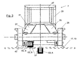
- the latch devices 7, which are detailed shown in Fig. 2 and 3 , each comprise a latch housing 25 mounted to the track housing 19 of the roller track 17 between two subsequent rollers 21, as well as a first latch claw 27 and a second latch claw 29 pivotably mounted to the latch housing 25 by means of a first hinge 31 and a second hinge 33.
- Each latch claw 27, 29 is pivotable between a latched position (see Fig. 2 ) and an unlatched position, wherein in the latched position the latch claws 27, 29 are adapted to engage a corresponding engagement section on the lower surface of a cargo unit received in the vehicle cargo compartment 1, and in the unlatched position the latch claws 27, 29 are adapted to disengage from said engagement section.
- first and second latch claws 27, 29 When first and second latch claws 27, 29 are in the latched position they project up over the level of the roller track 17 in which the rollers 21 are adapted to engage the lower surface of a cargo unit, thereby inhibiting the cargo units from being moved along the rollers 21 of the roller track 17.
- first and second latch claws 27, 29 When first and second latch claws 27, 29 are in the unlatched position they are retracted under the level of the roller track 17 in which the rollers 21 are adapted to engage the lower surface of a cargo unit, so that they do not inhibit the cargo units from being moved along the rollers 21.
- the first latch claw 27 comprises a first claw arm 35 and a first claw head 37 connected to said first claw arm 35 and adapted to engage the corresponding engagement section on a cargo unit received in the vehicle cargo compartment 1.
- the first claw arm 35 is mounted to the latch housing 25 pivotally by means of the first hinge 31, wherein an axis of rotation 39 of said first hinge 31 is parallel to the axes of rotation 23 of the rollers 21 in the roller track 17.
- the first claw arm 35 comprises an inner first arm section 41 extending between the first hinge 31 and the first claw head 37, and an outer first arm section 43 extending away from the first hinge 31 on that side of the first hinge 31 opposite from the inner first arm section 41.
- the second latch claw 29 comprises a second claw arm 45 and a second claw head 47 connected to said second claw arm 45 and adapted to engage the corresponding engagement section on a cargo unit received in the vehicle cargo compartment 1.
- the second claw arm 45 is mounted to the latch housing 25 pivotally by means of the second hinge 33, wherein an axis of rotation 49 of said second hinge 33 is parallel to the axis of rotation 39 of the first hinge 31.
- the second claw arm 45 comprises an inner second arm section 51 extending between the second hinge 33 and the second claw head 47, and an outer second arm section 53 extending away from the second hinge 33 on that side of the second hinge 33 opposite from the inner second arm section 51.
- the first latch claw 27 and the second latch claw 29 are arranged in such a manner that they pivot in reverse directions of rotation, when moved between the latched position and the unlatched position, so that the first claw head 37 and the second claw head 47 are arranged opposite to one another, when first and second latch claws 27, 29 are in the latched position, in order to effectively lock a cargo unit engaged by said latch claws 27, 29, i.e. inhibit a movement of said cargo unit to both opposite directions of the roller track 17.
- the first latch claw 27 and the second latch claw 29 are coupled by means of a spring element 55 connecting the outer first arm section 43 and the outer second arm section 53 in such a manner that it is biased, when first and second latch claws 27, 29 are in the unlatched position, urging first and second latch claws 27, 29 into the latched position.
- the vehicle cargo compartment 1 on each latch device 7 comprises a latch sensor system 57 in order to detect, whether the latch claws 27, 29 are in the latched position, and to provided the position status of the latch claws 27, 29, e.g. to the loadmaster of the aircraft, by means of a latch controller unit 59 and a latch status display device 61.
- Said latch sensor system 57 comprises a position sensor 63 and a target element 65, wherein said position sensor 63 is adapted for detecting a predetermined position of the target element 65 and generating a latch signal 67 when the target element 65 is in said predetermined position.
- the position sensor 63 in the described embodiment is formed as a magnetic proximity sensor, and the target element 65 is formed as a ferromagnetic metal piece.
- the position sensor 63 and the target element 65 may be arranged in several possible positions on the latch device 7, so as to detect when the latch claws 27, 29 are in the latched position.
- one of the position sensor 63 and the target element 65 is mounted to the first latch claw 27 and the other one of the position sensor 63 and the target element 65 is mounted to the latch housing 25, to the compartment housing 3, or to the second latch claw 29.
- three alternative positions of the position sensor 63 and the target element 65 are indicated.
- the position sensor 63 is mounted to the track housing 19 of the roller track 17 underneath the latch device 7 in such a way that it is directed upwards away from the housing floor 11, and the target element 65 is mounted to the inner first arm section 41 of the first claw arm 35.
- the position sensor 63 is mounted to the track housing 19 of the roller track 17 underneath the latch device 7 in such a way that it is directed in parallel to the axis of rotation 39 of the first hinge 31, and the target element 65 is mounted to the outer first arm section 43 of the first claw arm 35.
- the position sensor 63 is mounted to the first claw head 37 and the target element 65 is mounted to the second claw head 47, such that the position sensor 63 is facing the target element 65 when the first and second latch claws 27, 29 are in the latched position.
- the position sensor 63 and the target element 65 are arranged and adapted, i.e. the position sensor 63 has to be calibrated, in such a manner that the predetermined position of the target element 65 is detected and the latch signal 67 is generated, when the first latch claw 27 is in the latched position. In such a way it can be detected easily and reliably, whether the latch claws 27, 29 are in the latched position.
- the latch signals 67 generated by the position sensors 63 of all latch devices 7 of the described vehicle cargo compartment 1 are fed into the latch controller unit 59 which processes said latch signals 67 and provides a control signal 69 to the latch status display device 61 causing the latch status display device 61 to display a sign, e.g. to the loadmaster, indicating that the latch claws 27, 29 of all latch devices 7 are in the latched position.
Landscapes
- Engineering & Computer Science (AREA)
- Aviation & Aerospace Engineering (AREA)
- Chemical & Material Sciences (AREA)
- Combustion & Propulsion (AREA)
- Mechanical Engineering (AREA)
- Ocean & Marine Engineering (AREA)
- Lock And Its Accessories (AREA)
Abstract
Description
- The present invention relates to a vehicle cargo compartment, in particular an aircraft cargo compartment. Further aspects of the invention relate to a system of such a vehicle cargo compartment and at least one cargo unit received in said vehicle cargo compartment, as well as to a vehicle, in particular an aircraft, comprising such a vehicle cargo compartment.
- Said vehicle cargo compartment comprises a compartment housing and at least one latch device. The compartment housing is adapted for being received in a vehicle, in particular in an aircraft fuselage. The latch device is mounted to said compartment housing and adapted for locking a cargo unit received in said vehicle cargo compartment, in a fixed and predetermined position with respect to said compartment housing. Said cargo unit may be e.g. a "Unit Load Device" (ULD) commonly used for loading of an aircraft and in the form of a container or a pallet.
- Said latch device comprises a latch housing mounted to said compartment housing, and at least a first latch claw moveably mounted to said latch housing. Said first latch claw is moveable, preferably pivotable, between a latched position, where the first latch claw is adapted to engage a corresponding engagement section on a cargo unit received in the vehicle cargo compartment, and an unlatched position, where the first latch claw is adapted to disengage from said engagement section.
- Further, a latch sensor system is provided comprising a position sensor and a target element, said position sensor being adapted for detecting a predetermined position of the target element and generating a latch signal when the target element is in said predetermined position. The position sensor preferably is a magnetic proximity sensor and the target element preferably comprises a ferromagnetic metal material.
- One of the position sensor and the target element is mounted to the first latch claw and the other one of the position sensor and the target element is mounted alternatively either to the latch housing, to the compartment housing, or to a second latch claw which is moveably mounted to the latch housing.
- Such vehicle cargo compartments are known in the art of aircraft cargo systems. The known latch sensor system, i.e. the position sensor and the target element are positioned and adapted in such a manner that the position sensor detects the position of the target element and generates a latch signal, when the first latch claw and the second latch claw are in the unlatched position. In such a way, when it is detected that the latch claws are in the unlatched position a roller drive can be initiated driving one or more rollers installed on the compartment housing in a rotating manner, said rollers in turn engaging the outer surface of a cargo unit, thereby moving said cargo unit along the compartment housing without the cargo unit being restrained by the latch claws. However, with the arrangement of the latch sensor system known in the art it is merely possible to reliably detect when the latch claws are in the unlatched position.
- In connection with the vehicle cargo compartments known in the art, after completing the process of loading the cargo compartment with cargo units the loadmaster has to verify that each cargo unit is properly latched in its intended position in the compartment, so that it does not move during the flight. Such verifying is carried out manually, i.e. the loadmaster has to sight check each single latch device and each single cargo unit. This process takes a long time and at some particular aircraft types is very difficult to be handled, as their cargo compartments do not provide much space for the loadmaster to move along.
- Therefore, the object of the present invention is to provide a vehicle cargo compartment, where it can be monitored easily and reliably when the first latch claw is in the latched position.
- This object is achieved by the position sensor and the target element being arranged and adapted, in particular the position sensor is calibrated, in such a manner that the predetermined position of the target element is detected and the latch signal is generated, when the first latch claw is in the latched position.
- There are several possible options for the position sensor and the target element to be positioned on the first latch claw, the latch housing, or the compartment housing. One of the position sensor and the target element always has to be positioned on the first latch claw and the other one of the position sensor and the target element has to be positioned on one of the parts in relation to which the first latch claw can be moved, i.e. the latch housing and the compartment housing. Based on these positions of the position sensor and the target element with respect to one another the position sensor has to be directed to the position of the target element and configured to detect the target element in such cases, when the first latch claw with one of the position sensor and the target element attached thereto is moved to the latched position relative to either the latch housing or the compartment housing with the other one of the position sensor and the target element attached thereto.
- In such a manner when the first latch claw is in the latched position the latch signal is generated and provided to the loadmaster, e.g. by means of a simple lamp or an optical display device indicating that either one or all latch claws in the cargo compartment are in the latched position. The loadmaster does not need to sight check each latch device himself but can rely on the latch signal provided to him e.g. on the display device. The process of monitoring the latch status after loading the cargo compartment becomes considerably faster, easier, and more reliable in such a way. Further, it takes responsibility off the loadmaster.
- According to a preferred embodiment, the position sensor is arranged on the compartment housing and the target element is arranged on the first latch claw. In such a manner the position sensor may be arranged opposite the target element when the first latch claw is in the latched position, and no cables need to be installed on the moveable first latch claw. The positions of the position sensor and the target element may also be reversed.
- According to an alternative embodiment, the position sensor is arranged on the latch housing and the target element is arranged on the first latch claw. In such a manner the position sensor may be arranged opposite the target element when the first latch claw is in the latched position, and no cables need to be installed on the moveable first latch claw. The positions of the position sensor and the target element may also be reversed.
- According to another alternative embodiment, the position sensor is arranged on the first latch claw and the target element is arranged on the second latch claw. The second latch claw may be formed and configured in correspondence with the first latch claw, but may be moved in opposite direction so that the position sensor faces the target element when both first and second latch claws are in the latched position. In such a manner the latched position not only of the first latch claw but also of the second latch claw may be detected simultaneously. The positions of the position sensor and the target element may also be reversed.
- In a preferred embodiment the compartment housing comprises a housing floor and two opposite housing side walls at least partially surrounding a compartment interior space. The housing floor has an inner surface facing the compartment interior space. On said inner surface of the housing floor a roller track is provided extending in parallel to said housing side walls. The roller track comprises a track housing and a plurality of rollers rotatably mounted to said track housing. Each roller has an axis of rotation extending perpendicularly with respect to the direction of extension of the roller track. Said rollers being adapted to engage a lower surface of a cargo unit received in said vehicle cargo compartment. The cargo units may easily be slid on the rollers through the vehicle cargo compartment. At least a share of said rollers are driven by a roller drive in order to transport a cargo unit inside of the vehicle cargo compartment.
- In particular, it is preferred that the latch device is mounted to the track housing of the roller track between two subsequent rollers in such a manner that the first latch claw, when in the latched position, projects up over the level in which the rollers are adapted to engage the lower surface of a cargo unit, and when in the unlatched position, is retracted under the level in which the rollers are adapted to engage the lower surface of a cargo unit. A plurality of latch devices may be mounted to the track housing in preferably constant distances representing the desired positions of the cargo units intended to be received in the cargo compartment. In such a way a cargo unit may be slid over the rollers along the roller track, while the latch claws of the latch devices are in the unlatched position. When the desired position of the cargo unit is reached, the first latch claw is moved in the latched position engaging the corresponding engagement section on said cargo unit so as to lock the cargo unit in its position.
- Further, it is preferred that the first latch claw comprises a first claw arm and a first claw head connected to said first claw arm and adapted to engage a corresponding engagement section on a cargo unit received in the vehicle cargo compartment. The first claw arm is mounted to the latch housing pivotally by means of a first hinge. An axis of rotation of said first hinge being parallel to the axes of rotation of the rollers in the roller track. The first claw arm comprises an inner first arm section extending between the first hinge and the first claw head, and an outer first arm section extending away from the first hinge on that side of the first hinge opposite from the inner first arm section. In such a manner the first latch claw can be easily pivoted between latched and unlatched positions in the roller track.
- In a preferred embodiment the position sensor is mounted to the track housing underneath the latch device. In particular, it is preferred that the position sensor is directed upwards away from the housing floor, and that the target element is mounted to the inner first arm section of the first claw arm. In such a manner, the latched position of the first latch claw can be detected precisely and in a simple way.
- Alternatively, it is preferred that the position sensor is directed in parallel to the axis of rotation of the first hinge, and that the target element is mounted to the outer first arm section of the first claw arm. In such a manner, the latched position of the first latch claw can be detected precisely and in a simple way.
- In a preferred embodiment the second latch claw comprises a second claw arm and a second claw head connected to said second claw arm and adapted to engage a corresponding engagement section on a cargo unit received in the vehicle cargo compartment. The second claw arm is mounted to the latch housing pivotally by means of a second hinge, an axis of rotation of said second hinge being parallel to the axis of rotation of the first hinge. The second claw arm comprises an inner second arm section extending between the second hinge and the second claw head, and an outer second arm section extending away from the second hinge on that side of the second hinge opposite from the inner second arm section. The movement of the first latch claw and the second latch claw may be coupled, e.g. by means of a gear, or by a spring element biased between outer first arm section and outer second arm section in order to urge the first and second latch claws in the latched position. The positions or the forms of the first latch claw and the second latch claw may also be exchanged. By means of two separate latch claws engaging the cargo unit movement of said cargo unit in both opposite directions of the roller track can be inhibited.
- In particular, it is preferred that the first latch claw and the second latch claw are arranged such that they pivot in reverse directions of rotation, when moved between the latched position and the unlatched position. The first claw head and the second claw head are arranged opposite one another, when they are in the latched position. The position sensor is mounted to the first claw head and the target element is mounted to the second claw head, such that the position sensor is facing the target element when the first and second latch claws are in the latched position. In such a manner the latched position of the first latch claw as well as of the second latch claw can be detected at the same time. Of course, the position of the position sensor and the target element may also be exchanged, so that the position sensor is mounted to the second claw head and the target element is mounted to the first claw head.
- According to a further preferred embodiment a latch status display device is provided, said latch status display device being adapted to receive the latch signal generated by the position sensor and to display an optical sign indicating that the first and/or second latch claw is in the latched position. The latch status display device can be arranged in the vehicle cargo compartment or outside of the vehicle cargo compartment, so that the loadmaster can monitor the status of the latch devices, i.e., whether all latch claws are in the latched position. Additionally, a latch status display device may be provided in the cockpit for the pilot crew to monitor the latch status. The latch status display device in the most simple case may be a single lamp which is associated to each latch device, wherein a light shining in a lamp corresponds to the first latch claw of the associated latch device being in the latched position or in the unlatched position, respectively.
- Alternatively, a latch controller unit may be interconnected, wherein the latch signals of all latch devices are fed into the latch controller unit, which in turn may process these latch signals and may on the latch status display device provide a status of all latch devices including an indication of the exact latch device which is not latched. Alternatively, the operation of one or more systems of an aircraft comprising said vehicle cargo compartment may be inhibited by the latch controller unit, when it is detected that one of the latch claws is not in the latched position. The latch status display device may also be formed as or included in a mobile device connected to the latch controller unit by a wireless data connection.
- Further aspects of the invention concern a system of a vehicle cargo compartment as described before and at least one cargo unit received in said vehicle cargo compartment, as well as a vehicle, in particular an aircraft, comprising a vehicle cargo compartment as described above. The characteristics and advantages described before in connection with the vehicle cargo compartment also apply for said system and vehicle.
- In the following a preferred embodiment of the present invention is described by means of a drawing. The drawing shows in
- Fig. 1
- a perspective view of a vehicle cargo compartment according to the present invention, comprising a plurality of latch devices,
- Fig. 2
- a cross sectional view of a latch device installed in the vehicle cargo compartment of
Fig. 1 , the section plane extending in parallel to the direction of extension of the roller track, and - Fig. 3
- a cross sectional view of a latch device installed in the vehicle cargo compartment of
Fig. 1 , the section plane extending perpendicularly to the direction of extension of the roller track. - In
Fig. 1 a preferred embodiment of thevehicle cargo compartment 1, in the present case an aircraft cargo compartment, according to the present invention is shown. Saidvehicle cargo compartment 1 comprises acompartment housing 3 surrounding a compartmentinterior space 5, and a plurality oflatch devices 7 mounted to saidcompartment housing 3 in order to latch a plurality of cargo units (not shown) received in saidvehicle cargo compartment 1, in predetermined positions. - The
compartment housing 3 comprises ahousing floor 11 and two oppositehousing side walls 13 extending upwards from saidhousing floor 11. Thehousing floor 11 has aninner surface 15 facing the compartmentinterior space 5. On saidinner surface 15 of the housing floor 11 aroller track 17 is provided extending in parallel to thehousing side walls 13 along thehousing floor 11. Saidroller track 17 comprises a track housing 19 and a plurality ofrollers 21 rotatably mounted to said track housing 19 in such a manner that the axes ofrotation 23 of saidrollers 21 extend perpendicularly with respect to the direction of extension of theroller track 17 and with respect to thehousing side walls 13. Therollers 21 are arranged and adapted such that they engage a lower surface of a cargo unit (not shown) received in saidvehicle cargo compartment 1 in order for the cargo unit to be slid over therollers 21 along theroller track 17. - The
latch devices 7, which are detailed shown inFig. 2 and3 , each comprise alatch housing 25 mounted to the track housing 19 of theroller track 17 between twosubsequent rollers 21, as well as afirst latch claw 27 and asecond latch claw 29 pivotably mounted to thelatch housing 25 by means of afirst hinge 31 and asecond hinge 33. Eachlatch claw Fig. 2 ) and an unlatched position, wherein in the latched position thelatch claws vehicle cargo compartment 1, and in the unlatched position thelatch claws second latch claws roller track 17 in which therollers 21 are adapted to engage the lower surface of a cargo unit, thereby inhibiting the cargo units from being moved along therollers 21 of theroller track 17. When first andsecond latch claws roller track 17 in which therollers 21 are adapted to engage the lower surface of a cargo unit, so that they do not inhibit the cargo units from being moved along therollers 21. - First and
second latch claws first latch claw 27 comprises afirst claw arm 35 and afirst claw head 37 connected to saidfirst claw arm 35 and adapted to engage the corresponding engagement section on a cargo unit received in thevehicle cargo compartment 1. Thefirst claw arm 35 is mounted to thelatch housing 25 pivotally by means of thefirst hinge 31, wherein an axis ofrotation 39 of saidfirst hinge 31 is parallel to the axes ofrotation 23 of therollers 21 in theroller track 17. Thefirst claw arm 35 comprises an innerfirst arm section 41 extending between thefirst hinge 31 and thefirst claw head 37, and an outerfirst arm section 43 extending away from thefirst hinge 31 on that side of thefirst hinge 31 opposite from the innerfirst arm section 41. - The
second latch claw 29 comprises asecond claw arm 45 and asecond claw head 47 connected to saidsecond claw arm 45 and adapted to engage the corresponding engagement section on a cargo unit received in thevehicle cargo compartment 1. Thesecond claw arm 45 is mounted to thelatch housing 25 pivotally by means of thesecond hinge 33, wherein an axis ofrotation 49 of saidsecond hinge 33 is parallel to the axis ofrotation 39 of thefirst hinge 31. Thesecond claw arm 45 comprises an innersecond arm section 51 extending between thesecond hinge 33 and thesecond claw head 47, and an outersecond arm section 53 extending away from thesecond hinge 33 on that side of thesecond hinge 33 opposite from the innersecond arm section 51. - The
first latch claw 27 and thesecond latch claw 29 are arranged in such a manner that they pivot in reverse directions of rotation, when moved between the latched position and the unlatched position, so that thefirst claw head 37 and thesecond claw head 47 are arranged opposite to one another, when first andsecond latch claws latch claws roller track 17. Thefirst latch claw 27 and thesecond latch claw 29 are coupled by means of aspring element 55 connecting the outerfirst arm section 43 and the outersecond arm section 53 in such a manner that it is biased, when first andsecond latch claws second latch claws - Further, as shown in
Fig. 1 , thevehicle cargo compartment 1 on eachlatch device 7 comprises alatch sensor system 57 in order to detect, whether thelatch claws latch claws latch controller unit 59 and a latchstatus display device 61. Saidlatch sensor system 57 comprises aposition sensor 63 and atarget element 65, wherein saidposition sensor 63 is adapted for detecting a predetermined position of thetarget element 65 and generating a latch signal 67 when thetarget element 65 is in said predetermined position. Theposition sensor 63 in the described embodiment is formed as a magnetic proximity sensor, and thetarget element 65 is formed as a ferromagnetic metal piece. - As shown in
Fig. 2 and3 , theposition sensor 63 and thetarget element 65 may be arranged in several possible positions on thelatch device 7, so as to detect when thelatch claws position sensor 63 and thetarget element 65 is mounted to thefirst latch claw 27 and the other one of theposition sensor 63 and thetarget element 65 is mounted to thelatch housing 25, to thecompartment housing 3, or to thesecond latch claw 29. In the described embodiment, three alternative positions of theposition sensor 63 and thetarget element 65 are indicated. - According to the first alternative position A, the
position sensor 63 is mounted to the track housing 19 of theroller track 17 underneath thelatch device 7 in such a way that it is directed upwards away from thehousing floor 11, and thetarget element 65 is mounted to the innerfirst arm section 41 of thefirst claw arm 35. - According to the second alternative position B, the
position sensor 63 is mounted to the track housing 19 of theroller track 17 underneath thelatch device 7 in such a way that it is directed in parallel to the axis ofrotation 39 of thefirst hinge 31, and thetarget element 65 is mounted to the outerfirst arm section 43 of thefirst claw arm 35. - According to the third alternative position C, the
position sensor 63 is mounted to thefirst claw head 37 and thetarget element 65 is mounted to thesecond claw head 47, such that theposition sensor 63 is facing thetarget element 65 when the first andsecond latch claws - Whichever of the before described alternative positions A, B, C is chosen, according to the present invention the
position sensor 63 and thetarget element 65 are arranged and adapted, i.e. theposition sensor 63 has to be calibrated, in such a manner that the predetermined position of thetarget element 65 is detected and the latch signal 67 is generated, when thefirst latch claw 27 is in the latched position. In such a way it can be detected easily and reliably, whether thelatch claws - The latch signals 67 generated by the
position sensors 63 of alllatch devices 7 of the describedvehicle cargo compartment 1 are fed into thelatch controller unit 59 which processes said latch signals 67 and provides acontrol signal 69 to the latchstatus display device 61 causing the latchstatus display device 61 to display a sign, e.g. to the loadmaster, indicating that thelatch claws latch devices 7 are in the latched position.
Claims (15)
- A vehicle cargo compartment (1), comprising
a compartment housing (3) adapted for being received in a vehicle, and
at least one latch device (7) mounted to said compartment housing (3) and adapted for locking a cargo unit received in said vehicle cargo compartment (1), in a fixed position with respect to said compartment housing (3),
wherein said latch device (7) comprises a latch housing (25) mounted to said compartment housing (3), and at least a first latch claw (27) moveably mounted to said latch housing (25),
wherein said first latch claw (27) is moveable between a latched position, where the first latch claw (27) is adapted to engage a corresponding engagement section on a cargo unit received in the vehicle cargo compartment (1), and an unlatched position, where the first latch claw (27) is adapted to disengage from said engagement section,
wherein a latch sensor system (57) is provided comprising a position sensor (63) and a target element (65), said position sensor (63) being adapted for detecting a predetermined position of the target element (65) and generating a latch signal (67) when the target element (65) is in said predetermined position, and
wherein one of the position sensor (63) and the target element (65) is mounted to the first latch claw (27) and the other one of the position sensor (63) and the target element (65) is mounted to the latch housing (25), to the compartment housing (3), or to a second latch claw (29) moveably mounted to the latch housing (25),
characterized in
that the position sensor (63) and the target element (65) are arranged and adapted in such a manner that the predetermined position of the target element (65) is detected and the latch signal (67) is generated, when the first latch claw (27) is in the latched position. - A vehicle cargo compartment according to claim 1, wherein the position sensor (63) is arranged on the compartment housing (3) and the target element (65) is arranged on the first latch claw (27).
- A vehicle cargo compartment according to claim 1, wherein the position sensor (63) is arranged on the latch housing (25) and the target element (65) is arranged on the first latch claw (27).
- A vehicle cargo compartment according to claim 1, wherein the position sensor (63) is arranged on the first latch claw (27) and the target element (65) is arranged on the second latch claw (29).
- A vehicle cargo compartment according to any of claims 1 to 4, wherein the compartment housing (3) comprises a housing floor (11) and two opposite housing side walls (13) surrounding a compartment interior space (5),
wherein the housing floor (11) has an inner surface (15) facing the compartment interior space (5),
wherein on said inner surface (15) of the housing floor (11) a roller track (17) is provided extending in parallel to said housing side walls (13), and
wherein the roller track (17) comprises a track housing (19) and a plurality of rollers (21) rotatably mounted to said track housing (19), each roller (21) having an axis of rotation (23) extending perpendicularly with respect to the direction of extension of the roller track (17), and being adapted to engage a lower surface of a cargo unit received in said vehicle cargo compartment (1). - A vehicle cargo compartment according to claim 5, wherein the latch device (7) is mounted to the track housing (19) of the roller track (17) between two subsequent rollers (21) in such a manner that the first latch claw (27),
when in the latched position, projects up over the level in which the rollers (21) are adapted to engage the lower surface of a cargo unit, and
when in the unlatched position, is retracted under the level in which the rollers (21) are adapted to engage the lower surface of a cargo unit. - A vehicle cargo compartment according to claim 5 or 6, wherein the first latch claw (27) comprises a first claw arm (35) and a first claw head (37) connected to said first claw arm (35) and adapted to engage a corresponding engagement section on a cargo unit received in the vehicle cargo compartment (1),
wherein the first claw arm (35) is mounted to the latch housing (25) pivotally by means of a first hinge (31), an axis of rotation (39) of said first hinge (31) being parallel to the axes of rotation (23) of the rollers (21) in the roller track (17),
wherein the first claw arm (35) comprises an inner first arm section (41) extending between the first hinge (31) and the first claw head (37), and an outer first arm section (43) extending away from the first hinge (31) on that side of the first hinge (31) opposite from the inner first arm section (41). - A vehicle cargo compartment according to claim 5 to 7, when depending on claim 2, wherein the position sensor (63) is mounted to the track housing (19) underneath the latch device (7).
- A vehicle cargo compartment according to claim 8, when depending on claim 7, wherein the position sensor (63) is directed upwards away from the housing floor (11), and
wherein the target element (65) is mounted to the inner first arm section (41) of the first claw arm (35). - A vehicle cargo compartment according to claim 8, when depending on claim 7, wherein the position sensor (63) is directed in parallel to the axis of rotation (39) of the first hinge (31), and
wherein the target element (65) is mounted to the outer first arm section (43) of the first claw arm (35). - A vehicle cargo compartment according to claim 7, when depending on claim 4, wherein the second latch claw (29) comprises a second claw arm (45) and a second claw head (47) connected to said second claw arm (45) and adapted to engage a corresponding engagement section on a cargo unit received in the vehicle cargo compartment (1),
wherein the second claw arm (45) is mounted to the latch housing (25) pivotally by means of a second hinge (33), an axis of rotation (49) of said second hinge (33) being parallel to the axis of rotation (39) of the first hinge (31),
wherein the second claw arm (45) comprises an inner second arm section (51) extending between the second hinge (33) and the second claw head (47), and an outer second arm section (53) extending away from the second hinge (33) on that side of the second hinge (33) opposite from the inner second arm section (51). - A vehicle cargo compartment according to claim 11, wherein the first latch claw (27) and the second latch claw (29) are arranged such that they pivot in reverse directions of rotation, when moved between the latched position and the unlatched position,
wherein the first claw head (37) and the second claw head (47) are arranged opposite one another, when they are in the latched position, and
wherein the position sensor (63) is mounted to the first claw head (37) and the target element (65) is mounted to the second claw head (47), such that the position sensor (63) is facing the target element (65) when the first and second latch claws (27, 29) are in the latched position. - A vehicle cargo compartment according to any of claims 1 to 12, wherein a latch status display device (61) is provided, said latch status display device (61) being adapted to receive the latch signal (67) generated by the position sensor (63) and to display a sign indicating that the first latch claw (27) is in the latched position.
- A system of a vehicle cargo compartment (1) according to any of claims 1 to 13 and at least one cargo unit received in said vehicle cargo compartment (1).
- A vehicle comprising a vehicle cargo compartment (1) according to any of claims 1 to 13.
Priority Applications (2)
| Application Number | Priority Date | Filing Date | Title |
|---|---|---|---|
| EP14152741.6A EP2899124B1 (en) | 2014-01-27 | 2014-01-27 | Vehicle cargo compartment, system, and vehicle |
| US14/602,834 US9656750B2 (en) | 2014-01-27 | 2015-01-22 | Vehicle cargo compartment, system and vehicle |
Applications Claiming Priority (1)
| Application Number | Priority Date | Filing Date | Title |
|---|---|---|---|
| EP14152741.6A EP2899124B1 (en) | 2014-01-27 | 2014-01-27 | Vehicle cargo compartment, system, and vehicle |
Publications (2)
| Publication Number | Publication Date |
|---|---|
| EP2899124A1 true EP2899124A1 (en) | 2015-07-29 |
| EP2899124B1 EP2899124B1 (en) | 2018-07-25 |
Family
ID=49999819
Family Applications (1)
| Application Number | Title | Priority Date | Filing Date |
|---|---|---|---|
| EP14152741.6A Active EP2899124B1 (en) | 2014-01-27 | 2014-01-27 | Vehicle cargo compartment, system, and vehicle |
Country Status (2)
| Country | Link |
|---|---|
| US (1) | US9656750B2 (en) |
| EP (1) | EP2899124B1 (en) |
Cited By (3)
| Publication number | Priority date | Publication date | Assignee | Title |
|---|---|---|---|---|
| EP3556656A1 (en) * | 2018-04-18 | 2019-10-23 | The Boeing Company | Cargo restraint sensor system |
| EP4140883A3 (en) * | 2021-07-27 | 2023-03-29 | Goodrich Corporation | Latch state detection systems, methods and devices |
| EP4155203A1 (en) * | 2021-09-22 | 2023-03-29 | Airbus Operations GmbH | Aircraft and locking system for securing freight items in the hold of an aircraft |
Families Citing this family (4)
| Publication number | Priority date | Publication date | Assignee | Title |
|---|---|---|---|---|
| EP2899124B1 (en) * | 2014-01-27 | 2018-07-25 | Airbus Operations GmbH | Vehicle cargo compartment, system, and vehicle |
| CN106585770B (en) * | 2017-02-04 | 2020-02-04 | 上海速浦航空地面设备有限公司 | Container plate trailer plate turnover mechanism |
| US11186235B2 (en) * | 2017-11-17 | 2021-11-30 | Maintainer Corp. Of Iowa | Removable tool storage compartment |
| US10994662B2 (en) * | 2019-05-31 | 2021-05-04 | Ford Global Technologies, Llc | Tie-down bracket for motor vehicle |
Citations (4)
| Publication number | Priority date | Publication date | Assignee | Title |
|---|---|---|---|---|
| EP0541928A1 (en) * | 1991-11-11 | 1993-05-19 | Deutsche Aerospace Airbus Gesellschaft mit beschränkter Haftung | Locking device for holding freight in an aircraft |
| US6002350A (en) * | 1999-03-26 | 1999-12-14 | Checa; Humberto | Cargo movement detection system |
| DE102010035099A1 (en) * | 2010-08-23 | 2012-02-23 | Airbus Operations Gmbh | Fully automatic freight loading system |
| US20120312920A1 (en) * | 2009-11-30 | 2012-12-13 | Telair International Gmbh | Cargo Hold Floor for a Cargo Hold of an Aircraft, Function Element for Installing in a Cargo Hold Floor, Side Guide, Fixing Device for Introducing a Tensile Load, and Device for Ejecting Freight Items |
Family Cites Families (19)
| Publication number | Priority date | Publication date | Assignee | Title |
|---|---|---|---|---|
| US3741504A (en) * | 1971-05-06 | 1973-06-26 | Boeing Co | Cargo handling system |
| DE2432245B2 (en) * | 1974-07-05 | 1976-07-01 | Messerschmitt-Bölkow-Blohm GmbH, 8000 München | ROLLABLE DEVICE FOR LOCKING CARRIERS |
| US4234278A (en) * | 1978-10-31 | 1980-11-18 | Electro-Pneumatic International Gmbh | Locking devices for cargo and the like |
| US6193453B1 (en) * | 1997-07-24 | 2001-02-27 | Willem J. A. Kernkamp | Cargo lock for fixing cargo pallets to seat tracks in aircraft |
| US5950964A (en) * | 1998-06-25 | 1999-09-14 | Mcdonnell Douglas Corporation | Cargo guide |
| US6517028B2 (en) * | 2000-08-11 | 2003-02-11 | Telair International Gmbh | Freight loading system |
| US6488457B2 (en) * | 2001-03-05 | 2002-12-03 | The Boeing Company | Latching system for a palletized system of an aircraft |
| US6485238B2 (en) * | 2001-03-16 | 2002-11-26 | Pemco Aviation Group | Restraint apparatus |
| US6557800B2 (en) * | 2001-09-26 | 2003-05-06 | The Boeing Company | Cargo handling system for aircraft compartments |
| US7003374B2 (en) * | 2004-04-28 | 2006-02-21 | Goodrich Corporation | Aircraft cargo loading logistics system using machine readable identifiers |
| DE102004039666B4 (en) * | 2004-08-16 | 2008-09-04 | Airbus Deutschland Gmbh | Device for locking objects |
| US7530774B2 (en) * | 2007-07-13 | 2009-05-12 | Goodrich Corporation | Air cargo rollout stop |
| DE102008057076A1 (en) * | 2008-07-24 | 2010-02-04 | Telair International Gmbh | Loading system and method for loading a cargo space of an aircraft |
| US8690103B2 (en) * | 2010-01-19 | 2014-04-08 | Goodrich Corporation | Method and apparatus for converting aircraft from commercial to military freight service |
| WO2012098161A1 (en) * | 2011-01-19 | 2012-07-26 | Telair International Gmbh | Loading system for an aircraft, and method for conveying a piece of cargo on a cargo deck |
| EP2815969B1 (en) * | 2013-06-17 | 2018-08-08 | Airbus Operations GmbH | Cargo handling system |
| EP2865596B1 (en) * | 2013-10-23 | 2018-03-28 | Airbus Operations GmbH | Automatic transportation arrangement for cargo loading system |
| EP2899124B1 (en) * | 2014-01-27 | 2018-07-25 | Airbus Operations GmbH | Vehicle cargo compartment, system, and vehicle |
| DE102014105657A1 (en) * | 2014-04-22 | 2015-10-22 | Telair International Gmbh | Freight loading system for loading and unloading a freight item, method for creating and / or updating a loading plan |
-
2014
- 2014-01-27 EP EP14152741.6A patent/EP2899124B1/en active Active
-
2015
- 2015-01-22 US US14/602,834 patent/US9656750B2/en active Active
Patent Citations (4)
| Publication number | Priority date | Publication date | Assignee | Title |
|---|---|---|---|---|
| EP0541928A1 (en) * | 1991-11-11 | 1993-05-19 | Deutsche Aerospace Airbus Gesellschaft mit beschränkter Haftung | Locking device for holding freight in an aircraft |
| US6002350A (en) * | 1999-03-26 | 1999-12-14 | Checa; Humberto | Cargo movement detection system |
| US20120312920A1 (en) * | 2009-11-30 | 2012-12-13 | Telair International Gmbh | Cargo Hold Floor for a Cargo Hold of an Aircraft, Function Element for Installing in a Cargo Hold Floor, Side Guide, Fixing Device for Introducing a Tensile Load, and Device for Ejecting Freight Items |
| DE102010035099A1 (en) * | 2010-08-23 | 2012-02-23 | Airbus Operations Gmbh | Fully automatic freight loading system |
Cited By (5)
| Publication number | Priority date | Publication date | Assignee | Title |
|---|---|---|---|---|
| EP3556656A1 (en) * | 2018-04-18 | 2019-10-23 | The Boeing Company | Cargo restraint sensor system |
| US10988258B2 (en) | 2018-04-18 | 2021-04-27 | The Boeing Company | Cargo restraint sensor system |
| EP4140883A3 (en) * | 2021-07-27 | 2023-03-29 | Goodrich Corporation | Latch state detection systems, methods and devices |
| US12214900B2 (en) | 2021-07-27 | 2025-02-04 | Goodrich Corporation | Latch state detection systems, methods and devices |
| EP4155203A1 (en) * | 2021-09-22 | 2023-03-29 | Airbus Operations GmbH | Aircraft and locking system for securing freight items in the hold of an aircraft |
Also Published As
| Publication number | Publication date |
|---|---|
| US20150210391A1 (en) | 2015-07-30 |
| US9656750B2 (en) | 2017-05-23 |
| EP2899124B1 (en) | 2018-07-25 |
Similar Documents
| Publication | Publication Date | Title |
|---|---|---|
| EP2899124B1 (en) | Vehicle cargo compartment, system, and vehicle | |
| US20250384384A1 (en) | Enhanced systems, apparatus, and methods for positioning of an airborne relocatable communication hub supporting a plurality of wireless devices | |
| US10202065B2 (en) | System for moving loads comprising a locking arrangement that is operable by means of a transport vehicle | |
| EP3401217B1 (en) | Autonomous cargo handling system and method | |
| US9205930B2 (en) | Inclination detection device for aircraft, and method for loading and unloading cargo using same | |
| US11679875B2 (en) | Mechanism for docking a magnetic crawler into a UAV | |
| US8185234B2 (en) | Device and method for controlling the loading and/or unloading process of an airplane | |
| US10556683B2 (en) | Intelligent lock for cargo handling system | |
| US9751635B2 (en) | Indicating device for indicating an activation status of an escape slide in an aircraft | |
| CN110386256B (en) | Cargo restraint system and related method | |
| KR20160094597A (en) | Freight management system having function of real time monitoring | |
| EP2763888B1 (en) | Direct vehicle body locking sensor apparatus and method | |
| SE515352C2 (en) | Coupling device for a passenger bridge | |
| CN105711548B (en) | The automatic activation for the mist protection system that the vehicles carry | |
| US12085914B2 (en) | Systems and methods for operating multiple-level autonomous cargo handling systems | |
| CN109875380A (en) | Cooking equipment | |
| US11958628B2 (en) | Systems and methods for run-time self-assessment of cargo handling systems | |
| KR102105761B1 (en) | Auto leveler and control method thereof | |
| CN114126991A (en) | Transport device for transporting objects over a surface | |
| WO2025067606A1 (en) | Load securing device for transport vehicles and use thereof | |
| JP2017003540A (en) | Load monitoring system | |
| KR20180059109A (en) | Apparatus for loading and loading position verification |
Legal Events
| Date | Code | Title | Description |
|---|---|---|---|
| PUAI | Public reference made under article 153(3) epc to a published international application that has entered the european phase |
Free format text: ORIGINAL CODE: 0009012 |
|
| 17P | Request for examination filed |
Effective date: 20140127 |
|
| AK | Designated contracting states |
Kind code of ref document: A1 Designated state(s): AL AT BE BG CH CY CZ DE DK EE ES FI FR GB GR HR HU IE IS IT LI LT LU LV MC MK MT NL NO PL PT RO RS SE SI SK SM TR |
|
| AX | Request for extension of the european patent |
Extension state: BA ME |
|
| 17P | Request for examination filed |
Effective date: 20160122 |
|
| RBV | Designated contracting states (corrected) |
Designated state(s): AL AT BE BG CH CY CZ DE DK EE ES FI FR GB GR HR HU IE IS IT LI LT LU LV MC MK MT NL NO PL PT RO RS SE SI SK SM TR |
|
| 17Q | First examination report despatched |
Effective date: 20161011 |
|
| STAA | Information on the status of an ep patent application or granted ep patent |
Free format text: STATUS: EXAMINATION IS IN PROGRESS |
|
| GRAP | Despatch of communication of intention to grant a patent |
Free format text: ORIGINAL CODE: EPIDOSNIGR1 |
|
| STAA | Information on the status of an ep patent application or granted ep patent |
Free format text: STATUS: GRANT OF PATENT IS INTENDED |
|
| INTG | Intention to grant announced |
Effective date: 20180516 |
|
| GRAS | Grant fee paid |
Free format text: ORIGINAL CODE: EPIDOSNIGR3 |
|
| GRAA | (expected) grant |
Free format text: ORIGINAL CODE: 0009210 |
|
| STAA | Information on the status of an ep patent application or granted ep patent |
Free format text: STATUS: THE PATENT HAS BEEN GRANTED |
|
| AK | Designated contracting states |
Kind code of ref document: B1 Designated state(s): AL AT BE BG CH CY CZ DE DK EE ES FI FR GB GR HR HU IE IS IT LI LT LU LV MC MK MT NL NO PL PT RO RS SE SI SK SM TR |
|
| REG | Reference to a national code |
Ref country code: GB Ref legal event code: FG4D |
|
| REG | Reference to a national code |
Ref country code: CH Ref legal event code: EP |
|
| REG | Reference to a national code |
Ref country code: AT Ref legal event code: REF Ref document number: 1021472 Country of ref document: AT Kind code of ref document: T Effective date: 20180815 |
|
| REG | Reference to a national code |
Ref country code: IE Ref legal event code: FG4D |
|
| REG | Reference to a national code |
Ref country code: DE Ref legal event code: R096 Ref document number: 602014028963 Country of ref document: DE |
|
| REG | Reference to a national code |
Ref country code: NL Ref legal event code: MP Effective date: 20180725 |
|
| REG | Reference to a national code |
Ref country code: LT Ref legal event code: MG4D |
|
| PG25 | Lapsed in a contracting state [announced via postgrant information from national office to epo] |
Ref country code: NL Free format text: LAPSE BECAUSE OF FAILURE TO SUBMIT A TRANSLATION OF THE DESCRIPTION OR TO PAY THE FEE WITHIN THE PRESCRIBED TIME-LIMIT Effective date: 20180725 |
|
| REG | Reference to a national code |
Ref country code: AT Ref legal event code: MK05 Ref document number: 1021472 Country of ref document: AT Kind code of ref document: T Effective date: 20180725 |
|
| PG25 | Lapsed in a contracting state [announced via postgrant information from national office to epo] |
Ref country code: FI Free format text: LAPSE BECAUSE OF FAILURE TO SUBMIT A TRANSLATION OF THE DESCRIPTION OR TO PAY THE FEE WITHIN THE PRESCRIBED TIME-LIMIT Effective date: 20180725 Ref country code: BG Free format text: LAPSE BECAUSE OF FAILURE TO SUBMIT A TRANSLATION OF THE DESCRIPTION OR TO PAY THE FEE WITHIN THE PRESCRIBED TIME-LIMIT Effective date: 20181025 Ref country code: SE Free format text: LAPSE BECAUSE OF FAILURE TO SUBMIT A TRANSLATION OF THE DESCRIPTION OR TO PAY THE FEE WITHIN THE PRESCRIBED TIME-LIMIT Effective date: 20180725 Ref country code: AT Free format text: LAPSE BECAUSE OF FAILURE TO SUBMIT A TRANSLATION OF THE DESCRIPTION OR TO PAY THE FEE WITHIN THE PRESCRIBED TIME-LIMIT Effective date: 20180725 Ref country code: RS Free format text: LAPSE BECAUSE OF FAILURE TO SUBMIT A TRANSLATION OF THE DESCRIPTION OR TO PAY THE FEE WITHIN THE PRESCRIBED TIME-LIMIT Effective date: 20180725 Ref country code: IS Free format text: LAPSE BECAUSE OF FAILURE TO SUBMIT A TRANSLATION OF THE DESCRIPTION OR TO PAY THE FEE WITHIN THE PRESCRIBED TIME-LIMIT Effective date: 20181125 Ref country code: NO Free format text: LAPSE BECAUSE OF FAILURE TO SUBMIT A TRANSLATION OF THE DESCRIPTION OR TO PAY THE FEE WITHIN THE PRESCRIBED TIME-LIMIT Effective date: 20181025 Ref country code: LT Free format text: LAPSE BECAUSE OF FAILURE TO SUBMIT A TRANSLATION OF THE DESCRIPTION OR TO PAY THE FEE WITHIN THE PRESCRIBED TIME-LIMIT Effective date: 20180725 Ref country code: GR Free format text: LAPSE BECAUSE OF FAILURE TO SUBMIT A TRANSLATION OF THE DESCRIPTION OR TO PAY THE FEE WITHIN THE PRESCRIBED TIME-LIMIT Effective date: 20181026 Ref country code: PL Free format text: LAPSE BECAUSE OF FAILURE TO SUBMIT A TRANSLATION OF THE DESCRIPTION OR TO PAY THE FEE WITHIN THE PRESCRIBED TIME-LIMIT Effective date: 20180725 |
|
| PG25 | Lapsed in a contracting state [announced via postgrant information from national office to epo] |
Ref country code: LV Free format text: LAPSE BECAUSE OF FAILURE TO SUBMIT A TRANSLATION OF THE DESCRIPTION OR TO PAY THE FEE WITHIN THE PRESCRIBED TIME-LIMIT Effective date: 20180725 Ref country code: AL Free format text: LAPSE BECAUSE OF FAILURE TO SUBMIT A TRANSLATION OF THE DESCRIPTION OR TO PAY THE FEE WITHIN THE PRESCRIBED TIME-LIMIT Effective date: 20180725 Ref country code: HR Free format text: LAPSE BECAUSE OF FAILURE TO SUBMIT A TRANSLATION OF THE DESCRIPTION OR TO PAY THE FEE WITHIN THE PRESCRIBED TIME-LIMIT Effective date: 20180725 |
|
| REG | Reference to a national code |
Ref country code: DE Ref legal event code: R097 Ref document number: 602014028963 Country of ref document: DE |
|
| PG25 | Lapsed in a contracting state [announced via postgrant information from national office to epo] |
Ref country code: ES Free format text: LAPSE BECAUSE OF FAILURE TO SUBMIT A TRANSLATION OF THE DESCRIPTION OR TO PAY THE FEE WITHIN THE PRESCRIBED TIME-LIMIT Effective date: 20180725 Ref country code: IT Free format text: LAPSE BECAUSE OF FAILURE TO SUBMIT A TRANSLATION OF THE DESCRIPTION OR TO PAY THE FEE WITHIN THE PRESCRIBED TIME-LIMIT Effective date: 20180725 Ref country code: EE Free format text: LAPSE BECAUSE OF FAILURE TO SUBMIT A TRANSLATION OF THE DESCRIPTION OR TO PAY THE FEE WITHIN THE PRESCRIBED TIME-LIMIT Effective date: 20180725 Ref country code: CZ Free format text: LAPSE BECAUSE OF FAILURE TO SUBMIT A TRANSLATION OF THE DESCRIPTION OR TO PAY THE FEE WITHIN THE PRESCRIBED TIME-LIMIT Effective date: 20180725 Ref country code: RO Free format text: LAPSE BECAUSE OF FAILURE TO SUBMIT A TRANSLATION OF THE DESCRIPTION OR TO PAY THE FEE WITHIN THE PRESCRIBED TIME-LIMIT Effective date: 20180725 |
|
| PG25 | Lapsed in a contracting state [announced via postgrant information from national office to epo] |
Ref country code: SM Free format text: LAPSE BECAUSE OF FAILURE TO SUBMIT A TRANSLATION OF THE DESCRIPTION OR TO PAY THE FEE WITHIN THE PRESCRIBED TIME-LIMIT Effective date: 20180725 Ref country code: DK Free format text: LAPSE BECAUSE OF FAILURE TO SUBMIT A TRANSLATION OF THE DESCRIPTION OR TO PAY THE FEE WITHIN THE PRESCRIBED TIME-LIMIT Effective date: 20180725 Ref country code: SK Free format text: LAPSE BECAUSE OF FAILURE TO SUBMIT A TRANSLATION OF THE DESCRIPTION OR TO PAY THE FEE WITHIN THE PRESCRIBED TIME-LIMIT Effective date: 20180725 |
|
| PLBE | No opposition filed within time limit |
Free format text: ORIGINAL CODE: 0009261 |
|
| STAA | Information on the status of an ep patent application or granted ep patent |
Free format text: STATUS: NO OPPOSITION FILED WITHIN TIME LIMIT |
|
| 26N | No opposition filed |
Effective date: 20190426 |
|
| PG25 | Lapsed in a contracting state [announced via postgrant information from national office to epo] |
Ref country code: MC Free format text: LAPSE BECAUSE OF FAILURE TO SUBMIT A TRANSLATION OF THE DESCRIPTION OR TO PAY THE FEE WITHIN THE PRESCRIBED TIME-LIMIT Effective date: 20180725 Ref country code: SI Free format text: LAPSE BECAUSE OF FAILURE TO SUBMIT A TRANSLATION OF THE DESCRIPTION OR TO PAY THE FEE WITHIN THE PRESCRIBED TIME-LIMIT Effective date: 20180725 |
|
| REG | Reference to a national code |
Ref country code: CH Ref legal event code: PL |
|
| PG25 | Lapsed in a contracting state [announced via postgrant information from national office to epo] |
Ref country code: LU Free format text: LAPSE BECAUSE OF NON-PAYMENT OF DUE FEES Effective date: 20190127 |
|
| REG | Reference to a national code |
Ref country code: BE Ref legal event code: MM Effective date: 20190131 |
|
| REG | Reference to a national code |
Ref country code: IE Ref legal event code: MM4A |
|
| PG25 | Lapsed in a contracting state [announced via postgrant information from national office to epo] |
Ref country code: BE Free format text: LAPSE BECAUSE OF NON-PAYMENT OF DUE FEES Effective date: 20190131 |
|
| PG25 | Lapsed in a contracting state [announced via postgrant information from national office to epo] |
Ref country code: CH Free format text: LAPSE BECAUSE OF NON-PAYMENT OF DUE FEES Effective date: 20190131 Ref country code: LI Free format text: LAPSE BECAUSE OF NON-PAYMENT OF DUE FEES Effective date: 20190131 |
|
| PG25 | Lapsed in a contracting state [announced via postgrant information from national office to epo] |
Ref country code: IE Free format text: LAPSE BECAUSE OF NON-PAYMENT OF DUE FEES Effective date: 20190127 |
|
| PG25 | Lapsed in a contracting state [announced via postgrant information from national office to epo] |
Ref country code: TR Free format text: LAPSE BECAUSE OF FAILURE TO SUBMIT A TRANSLATION OF THE DESCRIPTION OR TO PAY THE FEE WITHIN THE PRESCRIBED TIME-LIMIT Effective date: 20180725 |
|
| PG25 | Lapsed in a contracting state [announced via postgrant information from national office to epo] |
Ref country code: MT Free format text: LAPSE BECAUSE OF NON-PAYMENT OF DUE FEES Effective date: 20190127 Ref country code: PT Free format text: LAPSE BECAUSE OF FAILURE TO SUBMIT A TRANSLATION OF THE DESCRIPTION OR TO PAY THE FEE WITHIN THE PRESCRIBED TIME-LIMIT Effective date: 20181125 |
|
| PG25 | Lapsed in a contracting state [announced via postgrant information from national office to epo] |
Ref country code: CY Free format text: LAPSE BECAUSE OF FAILURE TO SUBMIT A TRANSLATION OF THE DESCRIPTION OR TO PAY THE FEE WITHIN THE PRESCRIBED TIME-LIMIT Effective date: 20180725 |
|
| PG25 | Lapsed in a contracting state [announced via postgrant information from national office to epo] |
Ref country code: HU Free format text: LAPSE BECAUSE OF FAILURE TO SUBMIT A TRANSLATION OF THE DESCRIPTION OR TO PAY THE FEE WITHIN THE PRESCRIBED TIME-LIMIT; INVALID AB INITIO Effective date: 20140127 |
|
| PG25 | Lapsed in a contracting state [announced via postgrant information from national office to epo] |
Ref country code: MK Free format text: LAPSE BECAUSE OF FAILURE TO SUBMIT A TRANSLATION OF THE DESCRIPTION OR TO PAY THE FEE WITHIN THE PRESCRIBED TIME-LIMIT Effective date: 20180725 |
|
| PGFP | Annual fee paid to national office [announced via postgrant information from national office to epo] |
Ref country code: GB Payment date: 20260123 Year of fee payment: 13 |
|
| PGFP | Annual fee paid to national office [announced via postgrant information from national office to epo] |
Ref country code: DE Payment date: 20260121 Year of fee payment: 13 |
|
| PGFP | Annual fee paid to national office [announced via postgrant information from national office to epo] |
Ref country code: FR Payment date: 20260123 Year of fee payment: 13 |