EP2899066A1 - Armrest and seat arrangement comprising the same - Google Patents
Armrest and seat arrangement comprising the same Download PDFInfo
- Publication number
- EP2899066A1 EP2899066A1 EP14152804.2A EP14152804A EP2899066A1 EP 2899066 A1 EP2899066 A1 EP 2899066A1 EP 14152804 A EP14152804 A EP 14152804A EP 2899066 A1 EP2899066 A1 EP 2899066A1
- Authority
- EP
- European Patent Office
- Prior art keywords
- armrest
- lid
- arm
- support portion
- seat
- Prior art date
- Legal status (The legal status is an assumption and is not a legal conclusion. Google has not performed a legal analysis and makes no representation as to the accuracy of the status listed.)
- Granted
Links
- 210000000245 forearm Anatomy 0.000 description 2
- 230000007794 irritation Effects 0.000 description 2
- 230000001419 dependent effect Effects 0.000 description 1
Images



Classifications
-
- B—PERFORMING OPERATIONS; TRANSPORTING
- B64—AIRCRAFT; AVIATION; COSMONAUTICS
- B64D—EQUIPMENT FOR FITTING IN OR TO AIRCRAFT; FLIGHT SUITS; PARACHUTES; ARRANGEMENT OR MOUNTING OF POWER PLANTS OR PROPULSION TRANSMISSIONS IN AIRCRAFT
- B64D11/00—Passenger or crew accommodation; Flight-deck installations not otherwise provided for
- B64D11/06—Arrangements of seats, or adaptations or details specially adapted for aircraft seats
- B64D11/0639—Arrangements of seats, or adaptations or details specially adapted for aircraft seats with features for adjustment or converting of seats
- B64D11/0644—Adjustable arm rests
-
- B—PERFORMING OPERATIONS; TRANSPORTING
- B60—VEHICLES IN GENERAL
- B60N—SEATS SPECIALLY ADAPTED FOR VEHICLES; VEHICLE PASSENGER ACCOMMODATION NOT OTHERWISE PROVIDED FOR
- B60N2/00—Seats specially adapted for vehicles; Arrangement or mounting of seats in vehicles
- B60N2/75—Arm-rests
- B60N2/753—Arm-rests movable to an inoperative position
-
- B—PERFORMING OPERATIONS; TRANSPORTING
- B60—VEHICLES IN GENERAL
- B60N—SEATS SPECIALLY ADAPTED FOR VEHICLES; VEHICLE PASSENGER ACCOMMODATION NOT OTHERWISE PROVIDED FOR
- B60N2/00—Seats specially adapted for vehicles; Arrangement or mounting of seats in vehicles
- B60N2/75—Arm-rests
- B60N2/763—Arm-rests adjustable
- B60N2/77—Height adjustment
-
- B—PERFORMING OPERATIONS; TRANSPORTING
- B60—VEHICLES IN GENERAL
- B60N—SEATS SPECIALLY ADAPTED FOR VEHICLES; VEHICLE PASSENGER ACCOMMODATION NOT OTHERWISE PROVIDED FOR
- B60N2/00—Seats specially adapted for vehicles; Arrangement or mounting of seats in vehicles
- B60N2/75—Arm-rests
- B60N2/763—Arm-rests adjustable
- B60N2/777—Transversal adjustment
-
- B—PERFORMING OPERATIONS; TRANSPORTING
- B64—AIRCRAFT; AVIATION; COSMONAUTICS
- B64D—EQUIPMENT FOR FITTING IN OR TO AIRCRAFT; FLIGHT SUITS; PARACHUTES; ARRANGEMENT OR MOUNTING OF POWER PLANTS OR PROPULSION TRANSMISSIONS IN AIRCRAFT
- B64D11/00—Passenger or crew accommodation; Flight-deck installations not otherwise provided for
- B64D11/06—Arrangements of seats, or adaptations or details specially adapted for aircraft seats
- B64D11/0646—Seats characterised by special features of stationary arms, foot or head rests
Definitions
- the invention relates to an armrest for arrangement between two seats, especially two passenger seats of a vehicle such as an aircraft.
- the design of a seat armrest has usually fixed dimension including the armrest width.
- Today an aircraft cross section is designed to accommodate multiple seat blocks.
- the space offered to the passenger in transversal direction is often given by the width between armrests, which Airlines want to maximize, by reducing aisle or armrest width.
- An object of the invention is to enable an arrangement of more seats in a seat row within a given space. Another object of the invention is to provide more comfort without enlarging a space between the seats.
- a seat arrangement especially a passenger seat arrangement, with such an armrest according to the invention or according to preferred embodiments thereof as well as a passenger compartment such as an aircraft cabin with such an seat arrangement are indicated in the further independent claims.
- a further aspect addresses an aircraft provided with such seat arrangement.
- One preferred aspect of the invention proposes a transformable armrest to fulfill both needs:
- the invention provides an armrest for arrangement between two seats, especially two passenger seats of a vehicle such as an aircraft, comprising at least one first support portion for an arm of a first person and at least one second support portion for an arm of a second person wherein the first and second support portions provide different height levels.
- the armrest is adjustable to provide different height levels of the first and second support portions.
- a preferred embodiment of the invention provides an armrest for arrangement between two passenger seats of a vehicle, especially an aircraft, comprising at least one first support portion for a passenger's arm and at least one second support portion for a passenger's arm wherein the first and second support portions are adjustable to different height levels.
- the first and second support portion are arranged one after another in a longitudinal direction of the armrest.
- At least one of the supporting portions is adjustable in height and/or in width.
- At least one of the supporting portions comprises at least one wing element or lid being pivotally movable in an upward position to enlarge the height of the supporting portion and in a downward position to enlarge the width of the support portion.
- the at least one supporting portion comprises a first lid and a second lid pivotally movable in counter rotation manner between their upward and downward positions.
- the first and second lids are arranged and/or configured in a symmetrical manner with regard to a longitudinal center plane of the arm rest.
- the at least one lid is pivotable around a pivot axis wherein at least a component of the axis direction extends in longitudinal direction of the armrest.
- the at least one lid has a narrower first arm support surface extending in a tangential direction with regard to the pivot movement of the lid and a wider second arm support surface that extends parallel to a radial direction with regard to the pivot movement of the lid.
- a further aspect of the invention provides a seat arrangement for a vehicle, especially an aircraft, with a first seat and an adjacent second seat, characterized by an armrest according to the first aspect of the invention or according to the preferred embodiments thereof.
- This armrest is preferably arranged in the middle between the first and second passenger seats.
- the armrest is pivotally linked so that it can pivot between an essentially vertical arm rest position and an essentially horizontal arm rest position.
- the invention relates to a passenger compartment, especially aircraft cabin, comprising at least one of such seat arrangements.
- the invention relates to an aircraft comprising at least one of such seat arrangements.
- an armrest By using an armrest according to the invention, it is even possible to decrease a space between adjacent passenger seats without lowering the comfort of the passengers sharing an armrest.
- the seat arrangement of the invention makes it possible to arrange more seats in a row as compared with today's seat arrangements. For example, on a main deck of an Airbus A380, it is possible to have 11 seats in a row instead of 10.
- One preferred embodiment of the invention provides a foldable armrest.
- a solution to have more seats in a row is the specific configuration of the armrest.
- the upper surface of the armrest has at least two levels for the arms of the two passengers sitting side by side.
- the upper surface of the front part of the armrest is elevated relative to the upper surface of the back part. In this way one passenger can put his arm on the elevated front part, while his neighbour can put his arm on the relatively lower back part.
- the part forming the elevated surface comprises two pieces or plates oriented in parallel which can be unfolded, thus building a broad surface which is enough for carrying the arms of both passengers.
- the pieces can be turned around an axis which is oriented in a length direction of the armrest, to change from a position where both plates are vertically oriented and in parallel, to a position where both plates are horizontally oriented.
- An aspect of the invention has the advantage to solve the perennial problem of fighting for elbowroom in high-density seating in passengers compartments.
- a further advantage is to provide individual space for the arms of both persons seating at either side of the device without increasing the width of the division.
- a dual-user armrest In closed position, a dual-user armrest allows adjacent passengers to both use the armrest thanks to its two levels.
- a preferred embodiment provides a unique two levels individual armrest that allows two persons to share an armrest in places such as the aircraft cabin, cars, boats, trains, bus or theatres.
- the proposed armrest In open position the proposed armrest also makes more efficient use of space by creating a few extra inches or centimeters for passengers, as well as eliminating the "battle for the armrest" that is a major source of irritation and discomfort for many in economy class.
- a preferred design is based on ergonomic consideration to reconciliate the need to offer maximum space to the passenger between two consecutive armrests and comfortable support for arm and elbow in different positions of two adjacent passengers.
- Today typical armrest width in economy class is between 4.45 cm and 5.7 cm (1.75 and 2.25 inches), a preferred embodiment of the proposed invention offers a means to transform them to about 10 cm to about 15 cm (4 to 6 inches) and vice-versa.
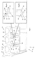
- Fig. 1 shows a schematic view of a part of the interior of a cabin 10 of an aircraft 12 as example for a passenger compartment 14 of a vehicle 16, comprising a seat arrangement 18.
- the seat arrangement 18 has several seats 20, 22, 23 with armrests 24 arranged between adjacent seats 20, 22 and 22, 23, respectively.
- the armrest 24 can also be arranged on both sides of a single seat or on both sides of the outer seats 20, 23 of the seat row 18.
- the armrest 24 between a first seat 20 and a second seat 22 is shown in a closed position 26.
- the armrest 24 between the second seat 22 and the third seat 23 is shown in an open position 28.
- the closed position 26 is shown in more detail in Fig. 1a
- the open position 28 of the armrest 24 is shown in more detail in Fig. 1 b.
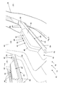
- Fig. 2 shows the situation when the seat arrangement 18 is occupied by neighbouring passengers 30, 32.
- Fig. 3 shows the seat arrangement 18 with the armrests 24 between the seats 20, 22; 22, 23 in the closed position 26 without passengers.
- the armrest 24 provides a first portion 34 for supporting the arm 35 of the first passenger 30 and a second support portion 36 for supporting the arm 38 of the neighbouring second passenger 32.
- the second support portion 36 is a backward portion that is arranged closer to the back rests 40 of the seats 20, 22, 23, while the first support portion 34 is arranged on a more forward portion or front portion.
- the support portions 34, 36 are arranged one after another in longitudinal direction of the armrest 24.
- the second support portion 36 is located between the first support portion 34 and the back rest 40.
- the first support portion 34 has, at least in the closed position 28, a different height level as the second support portion 36. In the embodiment shown, the first support portion 34 which is more forward has a higher level as the second support portion 36.
- the armrest 24 has a tip portion 70 at the free forward end having preferably the same height level as the second support portion 36.
- the second passenger 32 can support his elbow 42 on the second support portion 36, while the first passenger 30 can rest his forearm 43 on the first support portion 34.
- the first support portion 34 is adjacent to the second support portion 36 and both support portions 34, 36 do not overlap.
- the first support portion 34 is longer than the second support portion 36.
- the armrest 24 is quite narrow and takes only a small space between the seats 22, 23; 20, 22, it provides two different height levels 44, 46 which give more space for the arms 35, 38 of the passengers 30, 32.
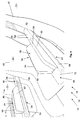
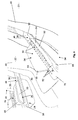
- the armrest 24 can be unfolded from the closed position 26 as shown in Fig. 3 into an open position 28 as shown in Fig. 7 ; intermediate positions are shown in Figs. 4 to 6 .
- the first support portion 34 has the same height level 46 as the second support portion 36, but has a larger width.
- the first support portion 34 comprises a first wing or lid 48 and a second wing or lid 50.
- the lids 48, 50 are pivotally movable about parallel pivot axes 52 extending into the longitudinal direction of the armrest 24.
- both lids 48, 50 are formed and arranged in a way that they have only one common axis 52 for their pivot movement or that only one of the lids 48, 50 is pivotally movable about one single axis 52. In the latter case, only one of the lids 48, 50 can be opened and thus moved in the horizontal position, while the remaining lid remains in the vertical position and thus provides privacy between the passengers.
- Both lids 48, 50 have a narrower first arm support surface 54 arranged on the smaller side of the lid 48, 50 and extending, hence, in a tangential direction with regard to the pivot axis 52. Further, both lids 50 have a wider second arm support surface 56 on the wider surface of the lid 48, 50.
- the at least one axis 52 for the pivot movement of the lids 48, 50 is arranged in the bottom portion of the lids 48, 50 when they are in the closed or vertical position. That means, during unfold movement into the open or horizontal position, the lids 48, 50 and in particular the surfaces 54 at the lateral end of each lid 48, 54 being on the opposite side of the one or two axes 52 move downward.
- Both lids 48, 50 are plate-shaped members pivotally linked to a base body 58 of the armrest 24 on one of the edges thereof while the first arm support surface 54 is located on the second, free-edge of the lid 48, 50.
- the second arm support surface 56 extends parallel to a radial direction with regard to the pivot axis 52.
- both first arm support surfaces 54 of the two lids 48, 50 form together a first platform 60 having the upper height level 44 of the first support portion 34.
- any second arm support surface 56 can be used by the respective passenger 30, 32, as shown in Fig. 8 .
- both second arm support surface 56 provide a much wider arm support surface in the lower height level 46.
- the lower height level 46 of the first support portion 34 has the same height level as the second support portion 36.
- the distance between the surfaces 54 of the two lids 48, 50 in the open position, i.e. the width of the support surface 56, is larger than the width of the second support portion 36.
- the lids 48, 50 are configured symmetrically with regard to a central longitudinal plane through the armrest 24. Both lids 48, 50 can be pivoted in a counter-rotating manner around their respective pivot axis 52.
- seat arrangement 18 and the armrest 24 to be used therein has been described using the example of a cabin 10 of an aircraft 12, similar armrests 24 and similar seat arrangements 18 can also be used in other vehicles 16 or in buildings, for example in buses, on boats, in trains or in theatres or cinemas or the like.
- the whole armrest 24 is pivotally fixed between the back rests 40 so that the whole armrest 24 can be pivoted in an essentially vertical position (not shown) or in the horizontal position as shown in the figures.
- Fig. 2 shows the armrest 24 in the closed position 26.
- the armrest 24 provides two separate platforms 60, 62 at two levels 44, 46 which are used as individual armrests. This gives each passenger 30, 32 its own wider armrest and the freedom of choice without increasing the width of the division 18.
- Fig. 3 to 7 show the deployment of the armrest 24.
- the armrest 24 is changed from the closed position 26 as shown in Fig. 2 and 3 to the open position 28 as shown in Fig. 7 and 8 .
- Fig. 8 shows the open position 28 in use by two neighbouring passengers 30, 32.
- the open position 28 provides horizontal surface 56 for two arms 35, 38.
- the dual-user armrest 24 allows adjacent passengers 30, 32 to both use the armrest 24 thanks to its new shape design in closed position 26 (e.g. Fig. 2 or 3 ).
- the armrest 24 also makes more efficient use of space by creating a few extra centimeters for passengers 30, 32, as well as eliminating the "battle for the armrest" that is a major source of irritation and discomfort for many in economy class.
Landscapes
- Engineering & Computer Science (AREA)
- Aviation & Aerospace Engineering (AREA)
- Transportation (AREA)
- Mechanical Engineering (AREA)
- Seats For Vehicles (AREA)
- Body Structure For Vehicles (AREA)
Abstract
Description
- The invention relates to an armrest for arrangement between two seats, especially two passenger seats of a vehicle such as an aircraft.
- In aircrafts, but also in other vehicles such as collective transport vehicles like buses or trains or in theatres or the like, there are seat arrangements wherein two neighbouring seats share an armrest. Especially in the economy class of aircrafts a "fight for the armrest" is often a cause for discomfort of the passengers.
- The design of a seat armrest has usually fixed dimension including the armrest width. Today an aircraft cross section is designed to accommodate multiple seat blocks. The space offered to the passenger in transversal direction is often given by the width between armrests, which Airlines want to maximize, by reducing aisle or armrest width.
- An object of the invention is to enable an arrangement of more seats in a seat row within a given space. Another object of the invention is to provide more comfort without enlarging a space between the seats.
- For addressing at least one of these objects the invention proposes an armrest as defined in claim 1.
- Advantageous embodiments of the invention are given in the dependent claims.
- A seat arrangement, especially a passenger seat arrangement, with such an armrest according to the invention or according to preferred embodiments thereof as well as a passenger compartment such as an aircraft cabin with such an seat arrangement are indicated in the further independent claims. A further aspect addresses an aircraft provided with such seat arrangement.
- One preferred aspect of the invention proposes a transformable armrest to fulfill both needs:
- increased lateral space for passenger when seated, and
- preserve the capability to increase the comfort of the armrest. The two adjacent passengers will not fight to find a place on the armrest.
- According to one aspect, the invention provides an armrest for arrangement between two seats, especially two passenger seats of a vehicle such as an aircraft, comprising at least one first support portion for an arm of a first person and at least one second support portion for an arm of a second person wherein the first and second support portions provide different height levels.
- Preferably, the armrest is adjustable to provide different height levels of the first and second support portions.
- A preferred embodiment of the invention provides an armrest for arrangement between two passenger seats of a vehicle, especially an aircraft, comprising at least one first support portion for a passenger's arm and at least one second support portion for a passenger's arm wherein the first and second support portions are adjustable to different height levels.
- Preferably, the first and second support portion are arranged one after another in a longitudinal direction of the armrest.
- Preferably, at least one of the supporting portions is adjustable in height and/or in width.
- Preferably, at least one of the supporting portions comprises at least one wing element or lid being pivotally movable in an upward position to enlarge the height of the supporting portion and in a downward position to enlarge the width of the support portion.
- Preferably, the at least one supporting portion comprises a first lid and a second lid pivotally movable in counter rotation manner between their upward and downward positions.
- Preferably, the first and second lids are arranged and/or configured in a symmetrical manner with regard to a longitudinal center plane of the arm rest.
- Preferably, the at least one lid is pivotable around a pivot axis wherein at least a component of the axis direction extends in longitudinal direction of the armrest.
- Preferably, the at least one lid has a narrower first arm support surface extending in a tangential direction with regard to the pivot movement of the lid and a wider second arm support surface that extends parallel to a radial direction with regard to the pivot movement of the lid.
- A further aspect of the invention provides a seat arrangement for a vehicle, especially an aircraft, with a first seat and an adjacent second seat, characterized by an armrest according to the first aspect of the invention or according to the preferred embodiments thereof. This armrest is preferably arranged in the middle between the first and second passenger seats.
- Preferably, the armrest is pivotally linked so that it can pivot between an essentially vertical arm rest position and an essentially horizontal arm rest position. According to a further aspect, the invention relates to a passenger compartment, especially aircraft cabin, comprising at least one of such seat arrangements.
- According to a further aspect, the invention relates to an aircraft comprising at least one of such seat arrangements.
- By using an armrest according to the invention, it is even possible to decrease a space between adjacent passenger seats without lowering the comfort of the passengers sharing an armrest.
- For example, the seat arrangement of the invention makes it possible to arrange more seats in a row as compared with today's seat arrangements. For example, on a main deck of an Airbus A380, it is possible to have 11 seats in a row instead of 10.
- One preferred embodiment of the invention provides a foldable armrest.
- A solution to have more seats in a row is the specific configuration of the armrest.
- Preferably, the upper surface of the armrest has at least two levels for the arms of the two passengers sitting side by side.
- For example, the upper surface of the front part of the armrest is elevated relative to the upper surface of the back part. In this way one passenger can put his arm on the elevated front part, while his neighbour can put his arm on the relatively lower back part.
- Preferably, the part forming the elevated surface comprises two pieces or plates oriented in parallel which can be unfolded, thus building a broad surface which is enough for carrying the arms of both passengers. The pieces can be turned around an axis which is oriented in a length direction of the armrest, to change from a position where both plates are vertically oriented and in parallel, to a position where both plates are horizontally oriented.
- An aspect of the invention has the advantage to solve the perennial problem of fighting for elbowroom in high-density seating in passengers compartments.
- A further advantage is to provide individual space for the arms of both persons seating at either side of the device without increasing the width of the division.
- In closed position, a dual-user armrest allows adjacent passengers to both use the armrest thanks to its two levels. A preferred embodiment provides a unique two levels individual armrest that allows two persons to share an armrest in places such as the aircraft cabin, cars, boats, trains, bus or theatres.
- In open position the proposed armrest also makes more efficient use of space by creating a few extra inches or centimeters for passengers, as well as eliminating the "battle for the armrest" that is a major source of irritation and discomfort for many in economy class.
- A preferred design is based on ergonomic consideration to reconciliate the need to offer maximum space to the passenger between two consecutive armrests and comfortable support for arm and elbow in different positions of two adjacent passengers.
- Today typical armrest width in economy class is between 4.45 cm and 5.7 cm (1.75 and 2.25 inches), a preferred embodiment of the proposed invention offers a means to transform them to about 10 cm to about 15 cm (4 to 6 inches) and vice-versa.
- Preferred embodiments of the invention are explained in more detail referring to the enclosed drawing.
- Fig. 1
- is a schematic view of a part of a cabin of an aircraft with a seat arrangement comprising armrests between the seats;
- Fig. 1a
- is a schematic view of one of the armrests between the seats in a closed position;
- Fig. 1b
- is a schematic view of one of the armrests between the seats in an open position;
- Fig. 2
- is a schematic perspective view of the seat arrangement with the armrest in the closed position in use by passengers;
- Fig. 3-7
- are views similar to
Fig. 2 without the passengers for showing different steps of deployment of the armrest between a closed position as shown inFig. 3 and an open position as shown inFig. 7 ; - Fig. 8
- is a view similar to
Fig. 7 with the armrest in an open position in use by passengers. -
Fig. 1 shows a schematic view of a part of the interior of acabin 10 of anaircraft 12 as example for apassenger compartment 14 of avehicle 16, comprising aseat arrangement 18. Theseat arrangement 18 hasseveral seats armrests 24 arranged betweenadjacent seats outer seats seat row 18. - The armrest 24 between a
first seat 20 and asecond seat 22 is shown in aclosed position 26. The armrest 24 between thesecond seat 22 and thethird seat 23 is shown in anopen position 28. Theclosed position 26 is shown in more detail inFig. 1a , while theopen position 28 of thearmrest 24 is shown in more detail inFig. 1 b. - The armrest 24 in the closed position is shown in more detail in
Figs. 2 and3 .Fig. 2 shows the situation when theseat arrangement 18 is occupied by neighbouringpassengers Fig. 3 shows theseat arrangement 18 with thearmrests 24 between theseats closed position 26 without passengers. - As visible from
Figs. 2 and3 , thearmrest 24 provides afirst portion 34 for supporting thearm 35 of thefirst passenger 30 and asecond support portion 36 for supporting thearm 38 of the neighbouringsecond passenger 32. - The
second support portion 36 is a backward portion that is arranged closer to the back rests 40 of theseats first support portion 34 is arranged on a more forward portion or front portion. Thesupport portions armrest 24. Thesecond support portion 36 is located between thefirst support portion 34 and theback rest 40. - The
first support portion 34 has, at least in theclosed position 28, a different height level as thesecond support portion 36. In the embodiment shown, thefirst support portion 34 which is more forward has a higher level as thesecond support portion 36. - Further, the
armrest 24 has atip portion 70 at the free forward end having preferably the same height level as thesecond support portion 36. - As visible from
Fig. 2 , thesecond passenger 32 can support hiselbow 42 on thesecond support portion 36, while thefirst passenger 30 can rest hisforearm 43 on thefirst support portion 34. - The
first support portion 34 is adjacent to thesecond support portion 36 and bothsupport portions - The
first support portion 34 is longer than thesecond support portion 36. - Hence, while the
armrest 24 is quite narrow and takes only a small space between theseats different height levels arms passengers - As visible from
Figs. 3 to 7 , the armrest 24 can be unfolded from theclosed position 26 as shown inFig. 3 into anopen position 28 as shown inFig. 7 ; intermediate positions are shown inFigs. 4 to 6 . - In the
open position 28, thefirst support portion 34 has thesame height level 46 as thesecond support portion 36, but has a larger width. - As visible from
Figs. 3 to 7 , thefirst support portion 34 comprises a first wing orlid 48 and a second wing orlid 50. Thelids armrest 24. - It is also possible that both
lids common axis 52 for their pivot movement or that only one of thelids single axis 52. In the latter case, only one of thelids - Both
lids arm support surface 54 arranged on the smaller side of thelid pivot axis 52. Further, bothlids 50 have a wider secondarm support surface 56 on the wider surface of thelid - The at least one
axis 52 for the pivot movement of thelids lids lids surfaces 54 at the lateral end of eachlid axes 52 move downward. - Both
lids base body 58 of the armrest 24 on one of the edges thereof while the firstarm support surface 54 is located on the second, free-edge of thelid arm support surface 56 extends parallel to a radial direction with regard to thepivot axis 52. - In the
closed position 26, both first arm support surfaces 54 of the twolids first platform 60 having theupper height level 44 of thefirst support portion 34. In theopen position 28, any secondarm support surface 56 can be used by therespective passenger Fig. 8 . In the unfolded position (open position 28), both secondarm support surface 56 provide a much wider arm support surface in thelower height level 46. Preferably, thelower height level 46 of thefirst support portion 34 has the same height level as thesecond support portion 36. - The distance between the
surfaces 54 of the twolids support surface 56, is larger than the width of thesecond support portion 36. - As further visible from
Figs. 3 to 8 , thelids armrest 24. Bothlids respective pivot axis 52. - While the
seat arrangement 18 and the armrest 24 to be used therein has been described using the example of acabin 10 of anaircraft 12,similar armrests 24 andsimilar seat arrangements 18 can also be used inother vehicles 16 or in buildings, for example in buses, on boats, in trains or in theatres or cinemas or the like. - Further, the
whole armrest 24 is pivotally fixed between the back rests 40 so that thewhole armrest 24 can be pivoted in an essentially vertical position (not shown) or in the horizontal position as shown in the figures. -
Fig. 2 shows the armrest 24 in theclosed position 26. Thearmrest 24 provides twoseparate platforms levels passenger division 18. -
Fig. 3 to 7 show the deployment of thearmrest 24. Thearmrest 24 is changed from theclosed position 26 as shown inFig. 2 and3 to theopen position 28 as shown inFig. 7 and8 . -
Fig. 8 shows theopen position 28 in use by two neighbouringpassengers open position 28 provideshorizontal surface 56 for twoarms user armrest 24 allowsadjacent passengers Fig. 2 or3 ). Onopen position 28 thearmrest 24 also makes more efficient use of space by creating a few extra centimeters forpassengers -
- 10
- cabin
- 12
- aircraft
- 14
- passenger compartment
- 16
- vehicle
- 18
- seat arrangement
- 20
- first seat
- 22
- second seat
- 23
- third seat
- 24
- armrest
- 26
- closed position
- 28
- open position
- 30
- first passenger
- 32
- second passenger
- 34
- first support portion
- 35
- arm (first passenger)
- 36
- second support portion
- 38
- arm (second passenger)
- 40
- back rest
- 42
- elbow
- 43
- forearm
- 44
- upper height level
- 46
- lower height level
- 48
- first lid
- 50
- second lid
- 52
- pivot axis
- 54
- first arm support surface
- 56
- second arm support surface
- 58
- base body of the armrest
- 60
- first platform
- 62
- second platform
- 70
- tip portion
Claims (13)
- Armrest (24) for arrangement between two seats (20, 22), especially two passenger seats of a vehicle such as an aircraft (12), comprising at least one first support portion (34) for an arm (35) of a first person and at least one second support portion (36) for an arm (38) of a second person wherein the first and second support portions (34, 36) provide different height levels (44, 46).
- Armrest (24) according to claim 1,
characterized in that armrest (24) is adjustable to provide different height levels (44, 46) of the first and second support portions (34, 36). - Armrest (24) according to claim 1 or 2,
characterized in that the first and second support portion (34, 36) are arranged one after another in a longitudinal direction of the armrest (24). - Armrest (24) according to any of the preceding claims,
characterized in that at least one of the supporting portions (34, 36) is adjustable in height and/or in width. - Armrest (24) according to any of the preceding claims,
characterized in that at least one of the supporting portions (34, 36) comprises at least one lid (48, 50) being pivotally movable in an upward position to enlarge the height of the supporting portion (34, 36) and in a downward position to enlarge the width of the support portion (34, 36). - Armrest (24) according to claim 5,
characterized in that the at least one supporting portion (34, 36) comprises a first lid (48) and a second lid (50) pivotally movable in counter rotation manner between their upward and downward positions. - Armrest (24) according to claim 6,
characterized in that the first and second lids (48, 50) are arranged and/or configured in a symmetrical manner with regard to a longitudinal center plane of the armrest (24). - Armrest (24) according to any of the claims 5 to 7,
characterized in that the at least one lid (48, 50) is pivotable around a pivot axis (52) wherein at least a component of the axis direction extends in longitudinal direction of the armrest (24). - Armrest (24) according to any of the claims 5 to 8,
characterized in that the at least one lid (48, 50) has a narrower first arm support surface (54) extending in a tangential direction with regard to the pivot movement of the lid (48, 50) and a wider second arm support surface (56) that extends parallel to a radial direction with regard to the pivot movement of the lid (48, 50). - Seat arrangement (18) for a vehicle (16), especially an aircraft (12), with a first seat (20) and an adjacent second seat (22),
characterized by an armrest (24) according to any of the preceding claims arranged in the middle between the first and second passenger seats (20, 22). - Seat arrangement (18) according to claim 10,
characterized in that the armrest (24) is pivotally linked so that it can pivot between an essentially vertical arm rest position and an essentially horizontal arm rest position. - Passenger compartment (14), especially aircraft cabin (10), comprising at least one seat arrangement (18) according to any of the claims 9 or 10.
- Aircraft (12) characterized by a passenger compartment (14) of claim 12 and/or a seat arrangement (18) according to any of the claims 10 to 11.
Priority Applications (3)
| Application Number | Priority Date | Filing Date | Title |
|---|---|---|---|
| EP14152804.2A EP2899066B1 (en) | 2014-01-28 | 2014-01-28 | Armrest and seat arrangement comprising the same |
| US14/606,129 US9630720B2 (en) | 2014-01-28 | 2015-01-27 | Armrest and seat arrangement comprising the same |
| CN201510043670.6A CN104802993B (en) | 2014-01-28 | 2015-01-28 | Handrail and the seat arrangement including the handrail |
Applications Claiming Priority (1)
| Application Number | Priority Date | Filing Date | Title |
|---|---|---|---|
| EP14152804.2A EP2899066B1 (en) | 2014-01-28 | 2014-01-28 | Armrest and seat arrangement comprising the same |
Publications (2)
| Publication Number | Publication Date |
|---|---|
| EP2899066A1 true EP2899066A1 (en) | 2015-07-29 |
| EP2899066B1 EP2899066B1 (en) | 2019-09-25 |
Family
ID=50000857
Family Applications (1)
| Application Number | Title | Priority Date | Filing Date |
|---|---|---|---|
| EP14152804.2A Active EP2899066B1 (en) | 2014-01-28 | 2014-01-28 | Armrest and seat arrangement comprising the same |
Country Status (3)
| Country | Link |
|---|---|
| US (1) | US9630720B2 (en) |
| EP (1) | EP2899066B1 (en) |
| CN (1) | CN104802993B (en) |
Cited By (1)
| Publication number | Priority date | Publication date | Assignee | Title |
|---|---|---|---|---|
| DE102014119600A1 (en) * | 2014-12-23 | 2016-06-23 | Recaro Aircraft Seating Gmbh & Co. Kg | Seating device with folding armrest unit |
Families Citing this family (23)
| Publication number | Priority date | Publication date | Assignee | Title |
|---|---|---|---|---|
| USRE47872E1 (en) | 2011-07-11 | 2020-02-25 | Molon Labe Llc | Slider seat for aircraft |
| US10104972B2 (en) * | 2014-03-29 | 2018-10-23 | Recaro Aircraft Seating Gmbh & Co. Kg | Shared armrest |
| JP2017043229A (en) * | 2015-08-27 | 2017-03-02 | トヨタ紡織株式会社 | Vehicle seat armrests and vehicle seats |
| US10179650B2 (en) * | 2016-03-10 | 2019-01-15 | B/E Aerospace, Inc. | Sliding seating unit panel for providing enhanced passenger ingress and egress |
| US10569881B2 (en) | 2016-10-18 | 2020-02-25 | Molon Labe, Llc | Staggered aircraft seat assembly |
| USD840701S1 (en) | 2017-10-18 | 2019-02-19 | Molon Labe, Llc | Staggered aircraft seats |
| USD850177S1 (en) | 2017-12-15 | 2019-06-04 | Molon Labe, Llc | Aircraft seat armrests |
| US10934002B2 (en) * | 2018-01-19 | 2021-03-02 | Ami Industries, Inc. | Aircraft passenger seat extended armrest |
| USD867775S1 (en) | 2018-04-03 | 2019-11-26 | Molon Labe, Llc | Set of multilevel aircraft seat armrests |
| US11535380B2 (en) * | 2018-07-31 | 2022-12-27 | Safran Seats Usa Llc | Rotating armrest assembly |
| US10611299B1 (en) * | 2018-09-18 | 2020-04-07 | The Boeing Company | Articulating armrest light assembly |
| US10870489B2 (en) * | 2019-05-24 | 2020-12-22 | B/E Aerospace, Inc. | Position adjustable armrest assemblies for passenger seats |
| USD936383S1 (en) | 2019-08-01 | 2021-11-23 | Molon Labe, Llc | Staggered aircraft seat assembly |
| USD924043S1 (en) | 2019-08-22 | 2021-07-06 | Molon Labe, Llc | Aircraft wheelchair accommodating seat assembly |
| US10953777B1 (en) * | 2019-08-30 | 2021-03-23 | The Boeing Company | Extendable armrest assemblies for passenger vehicle seating |
| WO2021080628A1 (en) * | 2019-10-25 | 2021-04-29 | Safran Seats Usa Llc | Passenger seat armrest with a multi-zone top surface |
| US11208212B2 (en) | 2019-10-28 | 2021-12-28 | B/E Aerospace, Inc. | Contoured armcap for multi-seat occupant usage |
| US11034454B1 (en) | 2019-11-06 | 2021-06-15 | B/E Aerospace, Inc. | Seat spreader mounted seat privacy closeout |
| DE102020106034A1 (en) * | 2020-03-05 | 2021-09-09 | Zim Flugsitz Gmbh | hinge |
| US11312498B2 (en) * | 2020-03-13 | 2022-04-26 | The Boeing Company | Convertible armrest disposed between adjacent seats |
| CN114348273B (en) * | 2022-01-12 | 2024-05-14 | 安徽陶铝新材料研究院有限公司 | Aviation seat ceramic aluminum sharing handrail |
| US12220066B2 (en) | 2022-01-22 | 2025-02-11 | B/E Aerospace, Inc. | Rotatable shared armrest |
| US11926421B2 (en) | 2022-08-11 | 2024-03-12 | The Boeing Company | Passenger seat armrest assembly |
Citations (4)
| Publication number | Priority date | Publication date | Assignee | Title |
|---|---|---|---|---|
| US20040164577A1 (en) * | 2002-07-25 | 2004-08-26 | Shabana Mohsen D. | Adjustable armrest |
| GB2455130A (en) * | 2007-11-29 | 2009-06-03 | James Shing Hin Lee | Dual armrest adapted for aircraft seats |
| US7748769B2 (en) * | 2005-09-06 | 2010-07-06 | Brose Fahrzeugteile Gmbh & Co. Kg, Coburg | Armrest subassembly for a motor vehicle |
| US20110043026A1 (en) * | 2009-08-19 | 2011-02-24 | Migdoel Miranda Montalvo | Armrest Device |
Family Cites Families (7)
| Publication number | Priority date | Publication date | Assignee | Title |
|---|---|---|---|---|
| US5597139A (en) * | 1994-04-15 | 1997-01-28 | Burns Aerospace Corporation | Convertible passenger seat assembly |
| DE19534024C2 (en) * | 1995-09-14 | 1997-07-10 | Daimler Benz Aerospace Airbus | Seating group, in particular in a passenger cabin of an aircraft |
| DE19611892C1 (en) * | 1996-03-26 | 1997-09-11 | Daimler Benz Ag | Central console for vehicle |
| US20090079228A1 (en) * | 2007-09-25 | 2009-03-26 | International Automotive Components Group North America, Inc. | Height adjustable armrest assembly |
| US9468302B2 (en) * | 2013-02-04 | 2016-10-18 | Isaac Negusse | Armrest expansion device |
| US9248765B2 (en) * | 2013-03-07 | 2016-02-02 | Ken Friedlander | Portable passenger seat divider |
| TWI572527B (en) * | 2015-06-04 | 2017-03-01 | 艾爾康太平洋股份有限公司 | Armrest structure and aircraft seat assebly thereof |
-
2014
- 2014-01-28 EP EP14152804.2A patent/EP2899066B1/en active Active
-
2015
- 2015-01-27 US US14/606,129 patent/US9630720B2/en not_active Expired - Fee Related
- 2015-01-28 CN CN201510043670.6A patent/CN104802993B/en active Active
Patent Citations (4)
| Publication number | Priority date | Publication date | Assignee | Title |
|---|---|---|---|---|
| US20040164577A1 (en) * | 2002-07-25 | 2004-08-26 | Shabana Mohsen D. | Adjustable armrest |
| US7748769B2 (en) * | 2005-09-06 | 2010-07-06 | Brose Fahrzeugteile Gmbh & Co. Kg, Coburg | Armrest subassembly for a motor vehicle |
| GB2455130A (en) * | 2007-11-29 | 2009-06-03 | James Shing Hin Lee | Dual armrest adapted for aircraft seats |
| US20110043026A1 (en) * | 2009-08-19 | 2011-02-24 | Migdoel Miranda Montalvo | Armrest Device |
Cited By (1)
| Publication number | Priority date | Publication date | Assignee | Title |
|---|---|---|---|---|
| DE102014119600A1 (en) * | 2014-12-23 | 2016-06-23 | Recaro Aircraft Seating Gmbh & Co. Kg | Seating device with folding armrest unit |
Also Published As
| Publication number | Publication date |
|---|---|
| US9630720B2 (en) | 2017-04-25 |
| US20150210395A1 (en) | 2015-07-30 |
| CN104802993B (en) | 2018-02-13 |
| CN104802993A (en) | 2015-07-29 |
| EP2899066B1 (en) | 2019-09-25 |
Similar Documents
| Publication | Publication Date | Title |
|---|---|---|
| US9630720B2 (en) | Armrest and seat arrangement comprising the same | |
| US11130577B2 (en) | Universal rest seats | |
| US11312497B2 (en) | Seat arrangement, in particular for an airplane | |
| EP2879907B1 (en) | Passenger suite seating arrangement with moveable video monitor | |
| US10549857B2 (en) | Airliner passenger suite seating arrangements with shared aisle suite access | |
| JP6058008B2 (en) | Advanced seat with retractable food tray and sliding armrest | |
| US8342450B2 (en) | Seating arrangement of a vehicle compartment | |
| EP3174789B1 (en) | Passenger suite seating arrangement with moveable video monitor | |
| US20140361585A1 (en) | Passenger suite seating arrangement with moveable video monitor | |
| US12122518B2 (en) | Seating arrangement | |
| EP2899125A1 (en) | Seat arrangement, aircraft cabin as well as armrest and seat or seat group for use therein | |
| US20160059966A1 (en) | Seating array for an aircraft cabin | |
| JP7463488B2 (en) | Passenger module, passenger seating arrangement | |
| US8746617B2 (en) | Aircraft cabin module and associated aircraft cabin equipped with same | |
| WO2009067028A2 (en) | Improvements relating to vehicle seating apparatus | |
| EP1645507A1 (en) | System for transportation and/or storage of persons in transportation vehicles |
Legal Events
| Date | Code | Title | Description |
|---|---|---|---|
| PUAI | Public reference made under article 153(3) epc to a published international application that has entered the european phase |
Free format text: ORIGINAL CODE: 0009012 |
|
| 17P | Request for examination filed |
Effective date: 20140128 |
|
| AK | Designated contracting states |
Kind code of ref document: A1 Designated state(s): AL AT BE BG CH CY CZ DE DK EE ES FI FR GB GR HR HU IE IS IT LI LT LU LV MC MK MT NL NO PL PT RO RS SE SI SK SM TR |
|
| AX | Request for extension of the european patent |
Extension state: BA ME |
|
| 17P | Request for examination filed |
Effective date: 20160129 |
|
| RBV | Designated contracting states (corrected) |
Designated state(s): AL AT BE BG CH CY CZ DE DK EE ES FI FR GB GR HR HU IE IS IT LI LT LU LV MC MK MT NL NO PL PT RO RS SE SI SK SM TR |
|
| STAA | Information on the status of an ep patent application or granted ep patent |
Free format text: STATUS: EXAMINATION IS IN PROGRESS |
|
| 17Q | First examination report despatched |
Effective date: 20181122 |
|
| REG | Reference to a national code |
Ref country code: DE Ref legal event code: R079 Ref document number: 602014054109 Country of ref document: DE Free format text: PREVIOUS MAIN CLASS: B60N0002460000 Ipc: B64D0011060000 |
|
| GRAP | Despatch of communication of intention to grant a patent |
Free format text: ORIGINAL CODE: EPIDOSNIGR1 |
|
| STAA | Information on the status of an ep patent application or granted ep patent |
Free format text: STATUS: GRANT OF PATENT IS INTENDED |
|
| RIC1 | Information provided on ipc code assigned before grant |
Ipc: B64D 11/06 20060101AFI20190322BHEP |
|
| INTG | Intention to grant announced |
Effective date: 20190417 |
|
| GRAS | Grant fee paid |
Free format text: ORIGINAL CODE: EPIDOSNIGR3 |
|
| GRAA | (expected) grant |
Free format text: ORIGINAL CODE: 0009210 |
|
| STAA | Information on the status of an ep patent application or granted ep patent |
Free format text: STATUS: THE PATENT HAS BEEN GRANTED |
|
| AK | Designated contracting states |
Kind code of ref document: B1 Designated state(s): AL AT BE BG CH CY CZ DE DK EE ES FI FR GB GR HR HU IE IS IT LI LT LU LV MC MK MT NL NO PL PT RO RS SE SI SK SM TR |
|
| REG | Reference to a national code |
Ref country code: GB Ref legal event code: FG4D |
|
| REG | Reference to a national code |
Ref country code: CH Ref legal event code: EP |
|
| REG | Reference to a national code |
Ref country code: DE Ref legal event code: R096 Ref document number: 602014054109 Country of ref document: DE |
|
| REG | Reference to a national code |
Ref country code: AT Ref legal event code: REF Ref document number: 1183591 Country of ref document: AT Kind code of ref document: T Effective date: 20191015 |
|
| REG | Reference to a national code |
Ref country code: IE Ref legal event code: FG4D |
|
| REG | Reference to a national code |
Ref country code: NL Ref legal event code: MP Effective date: 20190925 |
|
| PG25 | Lapsed in a contracting state [announced via postgrant information from national office to epo] |
Ref country code: BG Free format text: LAPSE BECAUSE OF FAILURE TO SUBMIT A TRANSLATION OF THE DESCRIPTION OR TO PAY THE FEE WITHIN THE PRESCRIBED TIME-LIMIT Effective date: 20191225 Ref country code: SE Free format text: LAPSE BECAUSE OF FAILURE TO SUBMIT A TRANSLATION OF THE DESCRIPTION OR TO PAY THE FEE WITHIN THE PRESCRIBED TIME-LIMIT Effective date: 20190925 Ref country code: LT Free format text: LAPSE BECAUSE OF FAILURE TO SUBMIT A TRANSLATION OF THE DESCRIPTION OR TO PAY THE FEE WITHIN THE PRESCRIBED TIME-LIMIT Effective date: 20190925 Ref country code: HR Free format text: LAPSE BECAUSE OF FAILURE TO SUBMIT A TRANSLATION OF THE DESCRIPTION OR TO PAY THE FEE WITHIN THE PRESCRIBED TIME-LIMIT Effective date: 20190925 Ref country code: FI Free format text: LAPSE BECAUSE OF FAILURE TO SUBMIT A TRANSLATION OF THE DESCRIPTION OR TO PAY THE FEE WITHIN THE PRESCRIBED TIME-LIMIT Effective date: 20190925 Ref country code: NO Free format text: LAPSE BECAUSE OF FAILURE TO SUBMIT A TRANSLATION OF THE DESCRIPTION OR TO PAY THE FEE WITHIN THE PRESCRIBED TIME-LIMIT Effective date: 20191225 |
|
| REG | Reference to a national code |
Ref country code: LT Ref legal event code: MG4D |
|
| PG25 | Lapsed in a contracting state [announced via postgrant information from national office to epo] |
Ref country code: LV Free format text: LAPSE BECAUSE OF FAILURE TO SUBMIT A TRANSLATION OF THE DESCRIPTION OR TO PAY THE FEE WITHIN THE PRESCRIBED TIME-LIMIT Effective date: 20190925 Ref country code: RS Free format text: LAPSE BECAUSE OF FAILURE TO SUBMIT A TRANSLATION OF THE DESCRIPTION OR TO PAY THE FEE WITHIN THE PRESCRIBED TIME-LIMIT Effective date: 20190925 Ref country code: GR Free format text: LAPSE BECAUSE OF FAILURE TO SUBMIT A TRANSLATION OF THE DESCRIPTION OR TO PAY THE FEE WITHIN THE PRESCRIBED TIME-LIMIT Effective date: 20191226 |
|
| REG | Reference to a national code |
Ref country code: AT Ref legal event code: MK05 Ref document number: 1183591 Country of ref document: AT Kind code of ref document: T Effective date: 20190925 |
|
| PG25 | Lapsed in a contracting state [announced via postgrant information from national office to epo] |
Ref country code: ES Free format text: LAPSE BECAUSE OF FAILURE TO SUBMIT A TRANSLATION OF THE DESCRIPTION OR TO PAY THE FEE WITHIN THE PRESCRIBED TIME-LIMIT Effective date: 20190925 Ref country code: PT Free format text: LAPSE BECAUSE OF FAILURE TO SUBMIT A TRANSLATION OF THE DESCRIPTION OR TO PAY THE FEE WITHIN THE PRESCRIBED TIME-LIMIT Effective date: 20200127 Ref country code: AT Free format text: LAPSE BECAUSE OF FAILURE TO SUBMIT A TRANSLATION OF THE DESCRIPTION OR TO PAY THE FEE WITHIN THE PRESCRIBED TIME-LIMIT Effective date: 20190925 Ref country code: NL Free format text: LAPSE BECAUSE OF FAILURE TO SUBMIT A TRANSLATION OF THE DESCRIPTION OR TO PAY THE FEE WITHIN THE PRESCRIBED TIME-LIMIT Effective date: 20190925 Ref country code: RO Free format text: LAPSE BECAUSE OF FAILURE TO SUBMIT A TRANSLATION OF THE DESCRIPTION OR TO PAY THE FEE WITHIN THE PRESCRIBED TIME-LIMIT Effective date: 20190925 Ref country code: IT Free format text: LAPSE BECAUSE OF FAILURE TO SUBMIT A TRANSLATION OF THE DESCRIPTION OR TO PAY THE FEE WITHIN THE PRESCRIBED TIME-LIMIT Effective date: 20190925 Ref country code: EE Free format text: LAPSE BECAUSE OF FAILURE TO SUBMIT A TRANSLATION OF THE DESCRIPTION OR TO PAY THE FEE WITHIN THE PRESCRIBED TIME-LIMIT Effective date: 20190925 Ref country code: PL Free format text: LAPSE BECAUSE OF FAILURE TO SUBMIT A TRANSLATION OF THE DESCRIPTION OR TO PAY THE FEE WITHIN THE PRESCRIBED TIME-LIMIT Effective date: 20190925 Ref country code: AL Free format text: LAPSE BECAUSE OF FAILURE TO SUBMIT A TRANSLATION OF THE DESCRIPTION OR TO PAY THE FEE WITHIN THE PRESCRIBED TIME-LIMIT Effective date: 20190925 |
|
| PG25 | Lapsed in a contracting state [announced via postgrant information from national office to epo] |
Ref country code: SM Free format text: LAPSE BECAUSE OF FAILURE TO SUBMIT A TRANSLATION OF THE DESCRIPTION OR TO PAY THE FEE WITHIN THE PRESCRIBED TIME-LIMIT Effective date: 20190925 Ref country code: CZ Free format text: LAPSE BECAUSE OF FAILURE TO SUBMIT A TRANSLATION OF THE DESCRIPTION OR TO PAY THE FEE WITHIN THE PRESCRIBED TIME-LIMIT Effective date: 20190925 Ref country code: SK Free format text: LAPSE BECAUSE OF FAILURE TO SUBMIT A TRANSLATION OF THE DESCRIPTION OR TO PAY THE FEE WITHIN THE PRESCRIBED TIME-LIMIT Effective date: 20190925 Ref country code: IS Free format text: LAPSE BECAUSE OF FAILURE TO SUBMIT A TRANSLATION OF THE DESCRIPTION OR TO PAY THE FEE WITHIN THE PRESCRIBED TIME-LIMIT Effective date: 20200224 |
|
| REG | Reference to a national code |
Ref country code: DE Ref legal event code: R097 Ref document number: 602014054109 Country of ref document: DE |
|
| PG2D | Information on lapse in contracting state deleted |
Ref country code: IS |
|
| PG25 | Lapsed in a contracting state [announced via postgrant information from national office to epo] |
Ref country code: DK Free format text: LAPSE BECAUSE OF FAILURE TO SUBMIT A TRANSLATION OF THE DESCRIPTION OR TO PAY THE FEE WITHIN THE PRESCRIBED TIME-LIMIT Effective date: 20190925 Ref country code: IS Free format text: LAPSE BECAUSE OF FAILURE TO SUBMIT A TRANSLATION OF THE DESCRIPTION OR TO PAY THE FEE WITHIN THE PRESCRIBED TIME-LIMIT Effective date: 20200126 |
|
| PLBE | No opposition filed within time limit |
Free format text: ORIGINAL CODE: 0009261 |
|
| STAA | Information on the status of an ep patent application or granted ep patent |
Free format text: STATUS: NO OPPOSITION FILED WITHIN TIME LIMIT |
|
| PG25 | Lapsed in a contracting state [announced via postgrant information from national office to epo] |
Ref country code: MC Free format text: LAPSE BECAUSE OF FAILURE TO SUBMIT A TRANSLATION OF THE DESCRIPTION OR TO PAY THE FEE WITHIN THE PRESCRIBED TIME-LIMIT Effective date: 20190925 |
|
| REG | Reference to a national code |
Ref country code: CH Ref legal event code: PL |
|
| 26N | No opposition filed |
Effective date: 20200626 |
|
| GBPC | Gb: european patent ceased through non-payment of renewal fee |
Effective date: 20200128 |
|
| REG | Reference to a national code |
Ref country code: BE Ref legal event code: MM Effective date: 20200131 |
|
| PG25 | Lapsed in a contracting state [announced via postgrant information from national office to epo] |
Ref country code: LU Free format text: LAPSE BECAUSE OF NON-PAYMENT OF DUE FEES Effective date: 20200128 Ref country code: GB Free format text: LAPSE BECAUSE OF NON-PAYMENT OF DUE FEES Effective date: 20200128 |
|
| PG25 | Lapsed in a contracting state [announced via postgrant information from national office to epo] |
Ref country code: LI Free format text: LAPSE BECAUSE OF NON-PAYMENT OF DUE FEES Effective date: 20200131 Ref country code: SI Free format text: LAPSE BECAUSE OF FAILURE TO SUBMIT A TRANSLATION OF THE DESCRIPTION OR TO PAY THE FEE WITHIN THE PRESCRIBED TIME-LIMIT Effective date: 20190925 Ref country code: BE Free format text: LAPSE BECAUSE OF NON-PAYMENT OF DUE FEES Effective date: 20200131 Ref country code: CH Free format text: LAPSE BECAUSE OF NON-PAYMENT OF DUE FEES Effective date: 20200131 |
|
| PG25 | Lapsed in a contracting state [announced via postgrant information from national office to epo] |
Ref country code: IE Free format text: LAPSE BECAUSE OF NON-PAYMENT OF DUE FEES Effective date: 20200128 |
|
| PG25 | Lapsed in a contracting state [announced via postgrant information from national office to epo] |
Ref country code: TR Free format text: LAPSE BECAUSE OF FAILURE TO SUBMIT A TRANSLATION OF THE DESCRIPTION OR TO PAY THE FEE WITHIN THE PRESCRIBED TIME-LIMIT Effective date: 20190925 Ref country code: MT Free format text: LAPSE BECAUSE OF FAILURE TO SUBMIT A TRANSLATION OF THE DESCRIPTION OR TO PAY THE FEE WITHIN THE PRESCRIBED TIME-LIMIT Effective date: 20190925 Ref country code: CY Free format text: LAPSE BECAUSE OF FAILURE TO SUBMIT A TRANSLATION OF THE DESCRIPTION OR TO PAY THE FEE WITHIN THE PRESCRIBED TIME-LIMIT Effective date: 20190925 |
|
| PG25 | Lapsed in a contracting state [announced via postgrant information from national office to epo] |
Ref country code: MK Free format text: LAPSE BECAUSE OF FAILURE TO SUBMIT A TRANSLATION OF THE DESCRIPTION OR TO PAY THE FEE WITHIN THE PRESCRIBED TIME-LIMIT Effective date: 20190925 |
|
| PGFP | Annual fee paid to national office [announced via postgrant information from national office to epo] |
Ref country code: DE Payment date: 20250121 Year of fee payment: 12 |
|
| PGFP | Annual fee paid to national office [announced via postgrant information from national office to epo] |
Ref country code: FR Payment date: 20250127 Year of fee payment: 12 |