EP2899030A1 - Radiant heat control with adjustable reflective element - Google Patents
Radiant heat control with adjustable reflective element Download PDFInfo
- Publication number
- EP2899030A1 EP2899030A1 EP15150772.0A EP15150772A EP2899030A1 EP 2899030 A1 EP2899030 A1 EP 2899030A1 EP 15150772 A EP15150772 A EP 15150772A EP 2899030 A1 EP2899030 A1 EP 2899030A1
- Authority
- EP
- European Patent Office
- Prior art keywords
- reflective element
- dryer
- web
- heat
- radiant energy
- Prior art date
- Legal status (The legal status is an assumption and is not a legal conclusion. Google has not performed a legal analysis and makes no representation as to the accuracy of the status listed.)
- Granted
Links
Images




Classifications
-
- B—PERFORMING OPERATIONS; TRANSPORTING
- B41—PRINTING; LINING MACHINES; TYPEWRITERS; STAMPS
- B41F—PRINTING MACHINES OR PRESSES
- B41F23/00—Devices for treating the surfaces of sheets, webs, or other articles in connection with printing
- B41F23/04—Devices for treating the surfaces of sheets, webs, or other articles in connection with printing by heat drying, by cooling, by applying powders
- B41F23/0403—Drying webs
- B41F23/0406—Drying webs by radiation
-
- B—PERFORMING OPERATIONS; TRANSPORTING
- B41—PRINTING; LINING MACHINES; TYPEWRITERS; STAMPS
- B41J—TYPEWRITERS; SELECTIVE PRINTING MECHANISMS, i.e. MECHANISMS PRINTING OTHERWISE THAN FROM A FORME; CORRECTION OF TYPOGRAPHICAL ERRORS
- B41J11/00—Devices or arrangements of selective printing mechanisms, e.g. ink-jet printers or thermal printers, for supporting or handling copy material in sheet or web form
- B41J11/0015—Devices or arrangements of selective printing mechanisms, e.g. ink-jet printers or thermal printers, for supporting or handling copy material in sheet or web form for treating before, during or after printing or for uniform coating or laminating the copy material before or after printing
- B41J11/002—Curing or drying the ink on the copy materials, e.g. by heating or irradiating
- B41J11/0021—Curing or drying the ink on the copy materials, e.g. by heating or irradiating using irradiation
- B41J11/00212—Controlling the irradiation means, e.g. image-based controlling of the irradiation zone or control of the duration or intensity of the irradiation
-
- B—PERFORMING OPERATIONS; TRANSPORTING
- B41—PRINTING; LINING MACHINES; TYPEWRITERS; STAMPS
- B41J—TYPEWRITERS; SELECTIVE PRINTING MECHANISMS, i.e. MECHANISMS PRINTING OTHERWISE THAN FROM A FORME; CORRECTION OF TYPOGRAPHICAL ERRORS
- B41J11/00—Devices or arrangements of selective printing mechanisms, e.g. ink-jet printers or thermal printers, for supporting or handling copy material in sheet or web form
- B41J11/0015—Devices or arrangements of selective printing mechanisms, e.g. ink-jet printers or thermal printers, for supporting or handling copy material in sheet or web form for treating before, during or after printing or for uniform coating or laminating the copy material before or after printing
- B41J11/002—Curing or drying the ink on the copy materials, e.g. by heating or irradiating
- B41J11/0021—Curing or drying the ink on the copy materials, e.g. by heating or irradiating using irradiation
- B41J11/00216—Curing or drying the ink on the copy materials, e.g. by heating or irradiating using irradiation using infrared [IR] radiation or microwaves
-
- B—PERFORMING OPERATIONS; TRANSPORTING
- B41—PRINTING; LINING MACHINES; TYPEWRITERS; STAMPS
- B41J—TYPEWRITERS; SELECTIVE PRINTING MECHANISMS, i.e. MECHANISMS PRINTING OTHERWISE THAN FROM A FORME; CORRECTION OF TYPOGRAPHICAL ERRORS
- B41J11/00—Devices or arrangements of selective printing mechanisms, e.g. ink-jet printers or thermal printers, for supporting or handling copy material in sheet or web form
- B41J11/0015—Devices or arrangements of selective printing mechanisms, e.g. ink-jet printers or thermal printers, for supporting or handling copy material in sheet or web form for treating before, during or after printing or for uniform coating or laminating the copy material before or after printing
- B41J11/002—Curing or drying the ink on the copy materials, e.g. by heating or irradiating
- B41J11/0021—Curing or drying the ink on the copy materials, e.g. by heating or irradiating using irradiation
- B41J11/00218—Constructional details of the irradiation means, e.g. radiation source attached to reciprocating print head assembly or shutter means provided on the radiation source
-
- B—PERFORMING OPERATIONS; TRANSPORTING
- B41—PRINTING; LINING MACHINES; TYPEWRITERS; STAMPS
- B41J—TYPEWRITERS; SELECTIVE PRINTING MECHANISMS, i.e. MECHANISMS PRINTING OTHERWISE THAN FROM A FORME; CORRECTION OF TYPOGRAPHICAL ERRORS
- B41J11/00—Devices or arrangements of selective printing mechanisms, e.g. ink-jet printers or thermal printers, for supporting or handling copy material in sheet or web form
- B41J11/0015—Devices or arrangements of selective printing mechanisms, e.g. ink-jet printers or thermal printers, for supporting or handling copy material in sheet or web form for treating before, during or after printing or for uniform coating or laminating the copy material before or after printing
- B41J11/002—Curing or drying the ink on the copy materials, e.g. by heating or irradiating
- B41J11/0024—Curing or drying the ink on the copy materials, e.g. by heating or irradiating using conduction means, e.g. by using a heated platen
- B41J11/00242—Controlling the temperature of the conduction means
-
- F—MECHANICAL ENGINEERING; LIGHTING; HEATING; WEAPONS; BLASTING
- F26—DRYING
- F26B—DRYING SOLID MATERIALS OR OBJECTS BY REMOVING LIQUID THEREFROM
- F26B13/00—Machines and apparatus for drying fabrics, fibres, yarns, or other materials in long lengths, with progressive movement
- F26B13/10—Arrangements for feeding, heating or supporting materials; Controlling movement, tension or position of materials
-
- F—MECHANICAL ENGINEERING; LIGHTING; HEATING; WEAPONS; BLASTING
- F26—DRYING
- F26B—DRYING SOLID MATERIALS OR OBJECTS BY REMOVING LIQUID THEREFROM
- F26B3/00—Drying solid materials or objects by processes involving the application of heat
- F26B3/28—Drying solid materials or objects by processes involving the application of heat by radiation, e.g. from the sun
-
- G—PHYSICS
- G02—OPTICS
- G02F—OPTICAL DEVICES OR ARRANGEMENTS FOR THE CONTROL OF LIGHT BY MODIFICATION OF THE OPTICAL PROPERTIES OF THE MEDIA OF THE ELEMENTS INVOLVED THEREIN; NON-LINEAR OPTICS; FREQUENCY-CHANGING OF LIGHT; OPTICAL LOGIC ELEMENTS; OPTICAL ANALOGUE/DIGITAL CONVERTERS
- G02F2203/00—Function characteristic
- G02F2203/02—Function characteristic reflective
-
- G—PHYSICS
- G02—OPTICS
- G02F—OPTICAL DEVICES OR ARRANGEMENTS FOR THE CONTROL OF LIGHT BY MODIFICATION OF THE OPTICAL PROPERTIES OF THE MEDIA OF THE ELEMENTS INVOLVED THEREIN; NON-LINEAR OPTICS; FREQUENCY-CHANGING OF LIGHT; OPTICAL LOGIC ELEMENTS; OPTICAL ANALOGUE/DIGITAL CONVERTERS
- G02F2203/00—Function characteristic
- G02F2203/11—Function characteristic involving infrared radiation
Definitions
- the present invention relates to the field of printing systems, and in particular, to radiant drying of ink applied to print media.
- a production printer is a high-speed printer used for volume printing (e.g., one hundred pages per minute or more).
- Production printers include continuous-forms printers that print on a web of print media stored on a large roll.
- a production printer typically includes a localized print controller that controls the overall operation of the printing system, and a print engine (sometimes referred to as an "imaging engine” or a “marking engine”).
- the print engine includes one or more printhead assemblies, with each assembly including a printhead controller and a printhead (or array of printheads).
- An individual printhead includes multiple tiny nozzles that are configured to discharge ink as controlled by the printhead controller.
- a printhead array is formed from multiple printheads that are spaced in series across the width of the web of print media.
- a radiant dryer installed downstream from the printer, may assist in drying the wet ink on the web after the web leaves the printer.
- a typical radiant dryer includes an array of radiant heat lamps. Drying the web can prove challenging due to variation of a number of factors, including the web's physical characteristics, speed of the web, print quality demands, etc. Moreover, insufficient drying may result in smearing while excessive drying may result in scorching, curling, and other defects. Therefore, precise control over the amount and location of heat applied to a web is desirable.
- Embodiments described herein provide for adjusting the reflectivity of a reflective element to control the amount and location of radiant heat in a dryer.
- a reflective element is placed in the dryer between a radiant heat source and a web. To increase the level of heat at the web surface, the reflective element is driven toward a transparent state. To decrease the level of heat at the web surface, the reflective element is driven toward a reflective state.
- the mirror may be driven to any range of reflective states, including fully reflective, fully transparent, and anything between (i.e., partial reflective) for precise heat control at the web, which allows for improved print quality.
- One embodiment is a dryer of a printing system.
- the drying includes a radiant energy source configured to apply heat to a print medium.
- the dryer also includes a reflective element installed between the radiant energy source and the print medium.
- the reflective element is configured to have varying levels of reflectance.
- the dryer also includes a controller configured to determine an amount of heat to supply to a region of the print medium, and to adjust an amount of reflectance of the reflective element based on the determined amount of heat.
- Another embodiment is a method.
- the method includes operating a heating element within an interior of a dryer.
- the method also includes determining an amount of heat to supply to one or more regions of the web.
- the method further includes adjusting an amount of reflectance of a reflective element based on the determined amount of heat.
- Yet another embodiment is a non-transitory computer readable medium embodying programmed instructions which, when executed by a processor, are configured for performing a method.
- the method includes operating a heating element within an interior of a dryer.
- the method also includes determining an amount of heat to supply to one or more regions of the web.
- the method further includes adjusting an amount of reflectance of a reflective element based on the determined amount of heat.
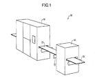
- FIG. 1 illustrates an exemplary continuous-forms printing system 100.
- Printing system 100 includes production printer 110, which is configured to apply ink onto a web 120 of continuous-form print media (e.g., paper).
- the word "ink” is used to refer to any suitable marking fluid (e.g., aqueous inks, oilbased paints, etc.).
- Printer 110 may comprise an inkjet printer that applies colored inks, such as Cyan (C), Magenta (M), Yellow (Y), Key (K) black, white, or clear inks.
- the ink applied by printer 110 to web is wet, meaning that the ink may smear if it is not dried before further processing.
- One or more rollers 130 position web 120 as it travels through printing system 100.
- printing system 100 also includes drying system 140 (e.g., a radiant dryer). Drying system 140 can be installed in printer 110, or can be implemented as an independent device downstream from printer 110 (as shown in FIG. 1 ). Web 120 travels through drying system 140 where an array of heating elements such as heat lamps (not shown) radiate thermal energy to dry the ink onto web 120.
- drying system 140 e.g., a radiant dryer. Drying system 140 can be installed in printer 110, or can be implemented as an independent device downstream from printer 110 (as shown in FIG. 1 ). Web 120 travels through drying system 140 where an array of heating elements such as heat lamps (not shown) radiate thermal energy to dry the ink onto web 120.
- drying ink onto web 120 can be a challenging process since conventional drying techniques (i.e., an array of heat lamps that emit infrared (IR) or near-infrared (NIR) energy and heat) have limited ability to regulate heat flux and target locations on the web. Additionally, the physical sizes of the lamps impose limits on the resolution of the heat targeting.
- conventional drying techniques i.e., an array of heat lamps that emit infrared (IR) or near-infrared (NIR) energy and heat
- IR infrared
- NIR near-infrared
- FIG. 2 shows a block diagram of drying system 200 in an exemplary embodiment.
- a source of radiant energy such as that supplied by one or more heating elements 220, heats a web 120 as the web 120 travels through the drying system 200.
- the web 120 may be tensioned by one or more rollers 130 as it travels through the drying system 200 in the direction indicated in FIG. 2 .
- Drying system 200 has been enhanced with a reflective element 210 that dynamically transitions between reflective and transparent states based on input from controller 230.
- reflective element 210 When reflective element 210 is in a fully reflective state, radiant energy from heating elements 220 is reflected back towards heating elements 220 such that the amount of heat that reaches the web 120 is eliminated or substantially reduced.
- reflective element 210 When reflective element 210 is in a fully transparent (i.e., transmissive) state, radiant energy from heating elements 220 passes through the reflective element 210 and onto the web 120 with little or no interruption from reflective element 210.
- reflective element 210 may enter virtually any state that is in-between fully reflective and fully transparent (i.e., partial reflectance, partial transparent) to produce a corresponding in-between level of heat at one or more regions of the web 120.
- Reflective element 210 may comprise any system, components, or device suitable to transition its reflectivity based on an input.
- reflective element 210 may comprise an electrochromic device that changes its reflectivity based on an application of a voltage supplied to its electrodes.
- reflective element 210 may comprise a transition metal switchable mirror (TMSM) which comprises a thin film of an alloy of magnesium and one or more transition metals. The film enables the glass to which it is bonded to be reversibly converted between reflective and transparent states either by applying an electrical current or exposing the film to hydrogen gas.
- TMSM transition metal switchable mirror
- reflective element 210 is disposed in a plane that is parallel to web 120 to minimize refraction distortion of the radiant energy supplied by heating elements 220.
- Controller 230 comprises any system, component, or device configured to control the reflectivity of reflective element 210. Controller 230 may drive, or transition, reflective element 210 to one reflective state or another based on, for example, sensor input, user input, print engine controller input, media type, media speed, ink type, ambient temperature, or other print related variables. In one embodiment, controller 230 includes a variable charge source driver that can apply a range of low voltages to reflective element 210 to induce corresponding ranges of reflectivity.
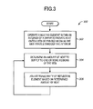
- FIG. 3 is a flowchart illustrating a method 300 for operating a drying system in an exemplary embodiment. The steps of method 300 are described with reference to drying system 200 of FIG. 2 , but those skilled in the art will appreciate that method 300 may be performed in other systems. The steps of the flowcharts described herein are not all inclusive and may include other steps not shown. The steps described herein may also be performed in an alternative order.
- heating elements 220 are operated to radiate broad spectrum energy onto web 120 as web 120 travels across the interior of drying system 200.
- heating elements 220 are heat lamps that are electrically powered to radiate thermal energy to heat web 120.
- controller 230 determines an amount of heat to supply to one or more regions of the web. The amount and/or location of heat may be based on a number of print related variables.
- controller 230 adjusts the reflective properties of reflective element 210 based on the amount and/or location of heat to be supplied to web 120.
- reflective element 210 passes an optimal amount of heat through it and onto web 120 under direction of controller 230.
- controller 230 may selectively cause a transition of the reflective properties of reflective element 210 to increase or decrease reflectivity and thereby cause a corresponding decrease or increase in the intensity of the heat that reaches web 120, respectively.
- Steps 304 and 306 may be repeated such that the controller 340 continually and adaptively adjusts/readjusts the reflectivity of reflective element 210 for dynamic heating of web 120.
- the increased control over the application of heat to the web 120 reduces deformities that can be caused by under heating or over heating the web 120.
- the reflective element 210 also advantageously allows for precise heat control and can substantially reduce, or eliminate, the need to adjust lamp output and orientation, particularly in situations where print related variables are changed.
- drying system 200 can collect heat in its upper section in the space above the reflective element 210.
- the reflective element 210 Upon a determination that an increased level of heat is to be provided at the surface of the web 120, the reflective element 210 is driven toward a transmissive state and the heat which has collected in the upper section is passed through the reflective element 210 and towards the web 120, thereby making highly efficient use of the heat within the drying system 200.
- FIG. 4 is a block diagram of an exemplary embodiment of a dryer system 400.
- Dryer system 400 configured with reflective element 410 and radiant energy sources 420, may collect excess heat in certain locations. Moreover, the surface of reflective element 410 may at times reach high temperatures.
- drying system 400 is enhanced with one or more transparent structures 430, which may comprise additional reflective elements, protective glass, lenses and/or optical filters. Additionally, transparent structures 430 may be positioned to create air channel(s) 440 and may also further be configured with one or more nozzle(s) 450 to circulate air throughout dryer system 400. Transparent structures 430 pass heat emitted from energy sources 420 with little or no interruption while providing various additional functionality as described in more detail below.
- transparent structures 430 may be disposed within dryer system 400 vertically above and/or vertically below reflective element 410.
- Transparent structures 430 may be adjacent to reflective element 410 (e.g., upper transparent structure 430 in FIG. 4 ) or disposed some distance relative to reflective element 410 (e.g., lower transparent structure 430 in FIG. 4 ) to create a space therebetween.
- the space between reflective element 410 and transparent structure 430 is used as a conduit to circulate a fluid (e.g., air channel 440 as shown in FIG. 4 ).
- conduits may be created by the space between two transparent structures 430 or included within transparent structure 430.
- lower transparent structure 430 includes two vertical channels for fluid passage.
- one or more nozzles 450 and/or vents may be disposed in the dryer system 400 to circulate or dissipate heat.
- the nozzles 450 may be controlled by a control system configured to regulate the temperature of reflective element 410 and/or other areas of the drying system 400. Temperature regulation may be based on, for example, temperature measurements of reflective element 410 or web 120.
- Nozzles 450 may also help dissipate moisture collected at the surface of web 120. In one example, and as shown in FIG. 4 , some nozzles 450 eject air horizontally in air channel 440, while other nozzles 450 route air at least some of the air downward toward web 120 to dissipate built-up moisture collected at the surface of web 120.
- dryer system 400 may additionally include moisture sensor/control and housing ventilation (not shown) to regulate dryer system 400 conditions.
- moisture sensor/control and housing ventilation not shown
- nozzles 450, air channel 440 and associated control may alternatively or additionally be configured to dissipate heat collected above reflective element 410.
- one or more of transparent structures 430 comprise sheet glass that protect the surface of reflective element 410 and prevent damage to objects that may contact reflective element 410. Additionally or alternatively, one or more transparent structures 430 comprise optical filters such as absorptive filters or dichroic/interference filters (e.g., "hot mirrors") that prevent specific wavelengths of energy emitted by energy sources 230 from reaching web 120, while allowing other wavelengths of light to pass through, heating web 120. As such, transparent structure 430 may help ensure no overheating occurs on the surface of reflective element 410 or web 120. Absorptive filter transparent structure 430 and/or sheet glass transparent structure 430 may optionally be combined with other embodiments described herein, such as with the cooling functionality described above.
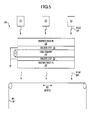
- FIG. 5 is a block diagram of another exemplary embodiment of a dryer system 500.
- FIG. 5 includes one or more grounded conductive layers 550/552 disposed around or adjacent to reflective element 510.
- Conductive layers 550/552 provide isolation between electrical components of dryer system 500 and reflective element 510 to reduce problems associated with electromagnetic interference (EMI) and electromagnetic compatibility (EMC).
- EMI electromagnetic interference
- EMC electromagnetic compatibility
- electromagnetic (EM) noise from the radiant energy sources 520 or static charge collected on the moving web 120 may drive the reflective element 510 to an undesirable reflective state through the electrical connections on the reflective element 510 and its drive circuits.
- EMI electromagnetic interference
- EMC electromagnetic compatibility
- conductive layers 550/552 comprise transparent conductor shielding over the surface of reflective element 510 so as not to impede the heat control capability of reflective element 410. Top and/or bottom surfaces of reflective element 410 may be coated with a transparent conductor that is grounded, and conductive layer 550/552 may be protected by transparent structure 530, such as glass. Conductive layers 550/552 may be uniform or alternatively formed in a grid pattern. In one embodiment, conductive layer 550/552 is comprised of indium tin oxide (ITO) deposited on the surface of reflective element 510 by a physical vapor deposition process, such as electron beam evaporation or a sputter deposition technique.
- ITO indium tin oxide
- FIG. 6 is a block diagram of a top view of another exemplary embodiment of a dryer 600.
- multiple switchable mirrors 610-614 are disposed in dryer 600 between one or more energy sources (not shown) and a web (e.g., narrow web 602 or wide web 604) of continuous-form print media.
- Each of switchable mirrors 610-614 may be independently controlled (e.g., by drive circuits V1-V3) and may cover different sectional areas within dryer 600 for increased granular control over the amount and location of heat that reaches the surface of web 602/604. Numerous variations are possible, switchable mirrors 610-614 may be adjacent to one another, in different vertical planes, in different horizontal planes, or disposed in dryer 600 as various combinations of the above.
- one or more switchable mirrors 610-614 may be additionally or alternatively disposed beneath the web 120.
- switchable mirrors 610-614 form independent segments of one monolithic switchable mirror.
- the segments are created by conductor layer areas surrounded by gaps, and each segment includes a corresponding set of electrodes used to independently control a corresponding portion of the monolithic switchable mirror.
- Each switchable mirror 610-614 and/or segment transitions its reflective properties based on an independent input.
- a matrix, or grid-like pattern is formed on a switchable mirror to create many independently controlled areas on the switchable mirror.
- TFT Thin Film Transistors
- LCDs Liquid Crystal Displays
- the arrangement of switchable mirrors 610-614 in dryer 600 allows controller 630 to target heat in accordance with print related characteristics, such as different web width sizes.
- One or more sensors e.g., sensor 640 located upstream and/or downstream from dryer 600 and/or reflective elements 610-614 may provide dynamic or static input to controller 630 regarding ink characteristics (e.g., amount, type, locations), web characteristics (e.g., type, speed, location, width), and/or temperature characteristics (e.g., dryer temperature, web temperature, temperature location) as the web travels.
- Controller 630 may independently drive each of switchable mirrors 610-614 to the appropriate level of reflectivity based on input from sensor 640 for optimal heat flux and location throughout dryer 600.
- Sensor 640 may comprise any system, component, or device configured to detect printer characteristics in one or more regions of the web 120.
- the sensor 640 may comprise a laser, pneumatic, photoelectric, ultrasonic, infrared, optical, thermocouple, or any other suitable type of sensing device.
- FIG. 7 is a block diagram of an exemplary embodiment of a system 700 with curved reflective elements.
- one or more curved reflective elements 710 having adjustable reflectivity are controlled to regulate the level of heat at the surface of the web 120, the surface of the drum 730, or both.
- Reflective element 710 may be disposed outside drum 730 and between radiant energy source 720 and web 120.
- reflective element 710 may be disposed within drum 730 to control conductive heat on one or more portions of the surface of drum 730 created from radiant energy source 722 inside drum 730.
- drum 730 is hollow with a thermal conductive surface.
- the curvature of reflective element(s) 710 is substantially similar to the curvature of drum 730 to minimize refraction distortion of the radiant energy.
- drum 730 and reflective element 710 being deployed externally to or without dryer housing.
- the system 700 may be used for multiple purposes, such as for drying ink or fusing toner onto a paper web.
- the arrangement and type of elements used may vary as desired in order to optimally provide heat to a web with a reflective element.
- different numbers, arrangements, and types of components of each embodiment may be used or combined as desired.
- the embodiments described may be applicable to other printer/dryer systems, such as non-continuous forms printer/dryer systems, solid ink printer/dryer systems, or electrophotographic toner printer/dryer systems.
- Embodiments disclosed herein can take the form of software, hardware, firmware, or various combinations thereof.
- software is used to direct a processing system of dryer system 200 to perform the various operations disclosed herein.
- FIG. 8 illustrates a processing system 800 configured to execute a computer readable medium embodying programmed instructions to perform desired functions in an exemplary embodiment.
- Processing system 800 is configured to perform the above operations by executing programmed instructions tangibly embodied on computer readable storage medium 812.
- embodiments of the invention can take the form of a computer program accessible via computer-readable medium 812 providing program code for use by a computer or any other instruction execution system.
- computer readable storage medium 812 can be anything that can contain or store the program for use by the computer.
- Computer readable storage medium 812 can be an electronic, magnetic, optical, electromagnetic, infrared, or semiconductor device. Examples of computer readable storage medium 812 include a solid state memory, a magnetic tape, a removable computer diskette, a random access memory (RAM), a read-only memory (ROM), a rigid magnetic disk, and an optical disk. Current examples of optical disks include compact disk - read only memory (CD-ROM), compact disk - read/write (CD-R/W), and DVD.
- CD-ROM compact disk - read only memory
- CD-R/W compact disk - read/write
- Processing system 800 being suitable for storing and/or executing the program code, includes at least one processor 802 coupled to program and data memory 804 through a system bus 850.
- Program and data memory 804 can include local memory employed during actual execution of the program code, bulk storage, and cache memories that provide temporary storage of at least some program code and/or data in order to reduce the number of times the code and/or data are retrieved from bulk storage during execution.
- I/O devices 806 can be coupled either directly or through intervening I/O controllers.
- Network adapter interfaces 808 may also be integrated with the system to enable processing system 800 to become coupled to other data processing systems or storage devices through intervening private or public networks. Modems, cable modems, IBM Channel attachments, SCSI, Fibre Channel, and Ethernet cards are just a few of the currently available types of network or host interface adapters.
- Presentation device interface 810 may be integrated with the system to interface to one or more presentation devices, such as printing systems and displays for presentation of presentation data generated by processor 802.
Landscapes
- Engineering & Computer Science (AREA)
- Health & Medical Sciences (AREA)
- General Health & Medical Sciences (AREA)
- Toxicology (AREA)
- Mechanical Engineering (AREA)
- General Engineering & Computer Science (AREA)
- Life Sciences & Earth Sciences (AREA)
- Microbiology (AREA)
- Textile Engineering (AREA)
- Supply, Installation And Extraction Of Printed Sheets Or Plates (AREA)
- Drying Of Solid Materials (AREA)
- Ink Jet (AREA)
Abstract
Description
- The present invention relates to the field of printing systems, and in particular, to radiant drying of ink applied to print media.
- Entities with substantial printing demands typically use a production printer. A production printer is a high-speed printer used for volume printing (e.g., one hundred pages per minute or more). Production printers include continuous-forms printers that print on a web of print media stored on a large roll.
- A production printer typically includes a localized print controller that controls the overall operation of the printing system, and a print engine (sometimes referred to as an "imaging engine" or a "marking engine"). The print engine includes one or more printhead assemblies, with each assembly including a printhead controller and a printhead (or array of printheads). An individual printhead includes multiple tiny nozzles that are configured to discharge ink as controlled by the printhead controller. A printhead array is formed from multiple printheads that are spaced in series across the width of the web of print media.
- While the printer prints, the web is quickly passed underneath the nozzles, which discharge ink onto the web at intervals to form pixels. A radiant dryer, installed downstream from the printer, may assist in drying the wet ink on the web after the web leaves the printer. A typical radiant dryer includes an array of radiant heat lamps. Drying the web can prove challenging due to variation of a number of factors, including the web's physical characteristics, speed of the web, print quality demands, etc. Moreover, insufficient drying may result in smearing while excessive drying may result in scorching, curling, and other defects. Therefore, precise control over the amount and location of heat applied to a web is desirable.
- Embodiments described herein provide for adjusting the reflectivity of a reflective element to control the amount and location of radiant heat in a dryer. A reflective element is placed in the dryer between a radiant heat source and a web. To increase the level of heat at the web surface, the reflective element is driven toward a transparent state. To decrease the level of heat at the web surface, the reflective element is driven toward a reflective state. The mirror may be driven to any range of reflective states, including fully reflective, fully transparent, and anything between (i.e., partial reflective) for precise heat control at the web, which allows for improved print quality.
- One embodiment is a dryer of a printing system. The drying includes a radiant energy source configured to apply heat to a print medium. The dryer also includes a reflective element installed between the radiant energy source and the print medium. The reflective element is configured to have varying levels of reflectance. The dryer also includes a controller configured to determine an amount of heat to supply to a region of the print medium, and to adjust an amount of reflectance of the reflective element based on the determined amount of heat.
- Another embodiment is a method. The method includes operating a heating element within an interior of a dryer. The method also includes determining an amount of heat to supply to one or more regions of the web. The method further includes adjusting an amount of reflectance of a reflective element based on the determined amount of heat.
- Yet another embodiment is a non-transitory computer readable medium embodying programmed instructions which, when executed by a processor, are configured for performing a method. The method includes operating a heating element within an interior of a dryer. The method also includes determining an amount of heat to supply to one or more regions of the web. The method further includes adjusting an amount of reflectance of a reflective element based on the determined amount of heat.
- Other exemplary embodiments (e.g., methods and computer-readable media relating to the foregoing embodiments) may be described below.
- Some embodiments of the present invention are now described, by way of example only, and with reference to the accompanying drawings. The same reference number represents the same element or the same type of element on all drawings.
-
FIG. 1 illustrates an exemplary continuous-forms printing system. -
FIG. 2 is a block diagram of a drying system in an exemplary embodiment. -
FIG. 3 is a flowchart illustrating a method for operating a drying system in an exemplary embodiment. -
FIGS. 4-6 are block diagrams illustrating drying systems in exemplary implementations. -
FIG. 7 is a block diagrams illustrating an exemplary system with curved reflective elements. -
FIG. 8 is block diagram of a processing system configured to execute a computer readable medium embodying programmed instructions to perform desired functions in an exemplary embodiment. - The figures and the following description illustrate specific exemplary embodiments of the invention. It will thus be appreciated that those skilled in the art will be able to devise various arrangements that, although not explicitly described or shown herein, embody the principles of the invention and are included within the scope of the invention. Furthermore, any examples described herein are intended to aid in understanding the principles of the invention, and are to be construed as being without limitation to such specifically recited examples and conditions. As a result, the invention is not limited to the specific embodiments or examples described below, but by the claims and their equivalents.
-
FIG. 1 illustrates an exemplary continuous-forms printing system 100.Printing system 100 includesproduction printer 110, which is configured to apply ink onto aweb 120 of continuous-form print media (e.g., paper). As used herein, the word "ink" is used to refer to any suitable marking fluid (e.g., aqueous inks, oilbased paints, etc.).Printer 110 may comprise an inkjet printer that applies colored inks, such as Cyan (C), Magenta (M), Yellow (Y), Key (K) black, white, or clear inks. The ink applied byprinter 110 to web is wet, meaning that the ink may smear if it is not dried before further processing. One ormore rollers 130position web 120 as it travels throughprinting system 100. - To dry ink,
printing system 100 also includes drying system 140 (e.g., a radiant dryer).Drying system 140 can be installed inprinter 110, or can be implemented as an independent device downstream from printer 110 (as shown inFIG. 1 ).Web 120 travels throughdrying system 140 where an array of heating elements such as heat lamps (not shown) radiate thermal energy to dry the ink ontoweb 120. - However, drying ink onto
web 120 can be a challenging process since conventional drying techniques (i.e., an array of heat lamps that emit infrared (IR) or near-infrared (NIR) energy and heat) have limited ability to regulate heat flux and target locations on the web. Additionally, the physical sizes of the lamps impose limits on the resolution of the heat targeting. -
FIG. 2 shows a block diagram ofdrying system 200 in an exemplary embodiment. A source of radiant energy, such as that supplied by one ormore heating elements 220, heats aweb 120 as theweb 120 travels through thedrying system 200. Theweb 120 may be tensioned by one ormore rollers 130 as it travels through thedrying system 200 in the direction indicated inFIG. 2 . -
Drying system 200 has been enhanced with areflective element 210 that dynamically transitions between reflective and transparent states based on input fromcontroller 230. Whenreflective element 210 is in a fully reflective state, radiant energy fromheating elements 220 is reflected back towardsheating elements 220 such that the amount of heat that reaches theweb 120 is eliminated or substantially reduced. Whenreflective element 210 is in a fully transparent (i.e., transmissive) state, radiant energy fromheating elements 220 passes through thereflective element 210 and onto theweb 120 with little or no interruption fromreflective element 210. Furthermore,reflective element 210 may enter virtually any state that is in-between fully reflective and fully transparent (i.e., partial reflectance, partial transparent) to produce a corresponding in-between level of heat at one or more regions of theweb 120. -
Reflective element 210 may comprise any system, components, or device suitable to transition its reflectivity based on an input. For example,reflective element 210 may comprise an electrochromic device that changes its reflectivity based on an application of a voltage supplied to its electrodes. In another example,reflective element 210 may comprise a transition metal switchable mirror (TMSM) which comprises a thin film of an alloy of magnesium and one or more transition metals. The film enables the glass to which it is bonded to be reversibly converted between reflective and transparent states either by applying an electrical current or exposing the film to hydrogen gas. In one embodiment,reflective element 210 is disposed in a plane that is parallel toweb 120 to minimize refraction distortion of the radiant energy supplied byheating elements 220. -
Controller 230 comprises any system, component, or device configured to control the reflectivity ofreflective element 210.Controller 230 may drive, or transition,reflective element 210 to one reflective state or another based on, for example, sensor input, user input, print engine controller input, media type, media speed, ink type, ambient temperature, or other print related variables. In one embodiment,controller 230 includes a variable charge source driver that can apply a range of low voltages toreflective element 210 to induce corresponding ranges of reflectivity. - Illustrative details of the operation of drying
system 200 will be discussed with regard toFIG. 3 . Assume, for this embodiment, that an upstream printer has markedweb 120, and thatweb 120 is being received at dryingsystem 200 for processing.FIG. 3 is a flowchart illustrating amethod 300 for operating a drying system in an exemplary embodiment. The steps ofmethod 300 are described with reference to dryingsystem 200 ofFIG. 2 , but those skilled in the art will appreciate thatmethod 300 may be performed in other systems. The steps of the flowcharts described herein are not all inclusive and may include other steps not shown. The steps described herein may also be performed in an alternative order. - At
step 302,heating elements 220 are operated to radiate broad spectrum energy ontoweb 120 asweb 120 travels across the interior of dryingsystem 200. In one embodiment,heating elements 220 are heat lamps that are electrically powered to radiate thermal energy to heatweb 120. Atstep 304,controller 230 determines an amount of heat to supply to one or more regions of the web. The amount and/or location of heat may be based on a number of print related variables. - At
step 306,controller 230 adjusts the reflective properties ofreflective element 210 based on the amount and/or location of heat to be supplied toweb 120. Thus,reflective element 210 passes an optimal amount of heat through it and ontoweb 120 under direction ofcontroller 230. For instance,controller 230 may selectively cause a transition of the reflective properties ofreflective element 210 to increase or decrease reflectivity and thereby cause a corresponding decrease or increase in the intensity of the heat that reachesweb 120, respectively. -
Steps reflective element 210 for dynamic heating ofweb 120. The increased control over the application of heat to theweb 120 reduces deformities that can be caused by under heating or over heating theweb 120. Thereflective element 210 also advantageously allows for precise heat control and can substantially reduce, or eliminate, the need to adjust lamp output and orientation, particularly in situations where print related variables are changed. Moreover, when thereflective element 210 is driven toward a reflective state, dryingsystem 200 can collect heat in its upper section in the space above thereflective element 210. Upon a determination that an increased level of heat is to be provided at the surface of theweb 120, thereflective element 210 is driven toward a transmissive state and the heat which has collected in the upper section is passed through thereflective element 210 and towards theweb 120, thereby making highly efficient use of the heat within thedrying system 200. -
FIG. 4 is a block diagram of an exemplary embodiment of adryer system 400.Dryer system 400, configured withreflective element 410 andradiant energy sources 420, may collect excess heat in certain locations. Moreover, the surface ofreflective element 410 may at times reach high temperatures. To help cool areas ofdryer system 400 and prevent damage to printing components therein, dryingsystem 400 is enhanced with one or moretransparent structures 430, which may comprise additional reflective elements, protective glass, lenses and/or optical filters. Additionally,transparent structures 430 may be positioned to create air channel(s) 440 and may also further be configured with one or more nozzle(s) 450 to circulate air throughoutdryer system 400.Transparent structures 430 pass heat emitted fromenergy sources 420 with little or no interruption while providing various additional functionality as described in more detail below. - As shown in
FIG. 4 ,transparent structures 430 may be disposed withindryer system 400 vertically above and/or vertically belowreflective element 410.Transparent structures 430 may be adjacent to reflective element 410 (e.g., uppertransparent structure 430 inFIG. 4 ) or disposed some distance relative to reflective element 410 (e.g., lowertransparent structure 430 inFIG. 4 ) to create a space therebetween. In one embodiment, the space betweenreflective element 410 andtransparent structure 430 is used as a conduit to circulate a fluid (e.g.,air channel 440 as shown inFIG. 4 ). Alternatively or additionally, conduits may be created by the space between twotransparent structures 430 or included withintransparent structure 430. For instance, as shown inFIG. 4 , lowertransparent structure 430 includes two vertical channels for fluid passage. - Additionally, one or
more nozzles 450 and/or vents may be disposed in thedryer system 400 to circulate or dissipate heat. Thenozzles 450 may be controlled by a control system configured to regulate the temperature ofreflective element 410 and/or other areas of thedrying system 400. Temperature regulation may be based on, for example, temperature measurements ofreflective element 410 orweb 120.Nozzles 450 may also help dissipate moisture collected at the surface ofweb 120. In one example, and as shown inFIG. 4 , somenozzles 450 eject air horizontally inair channel 440, whileother nozzles 450 route air at least some of the air downward towardweb 120 to dissipate built-up moisture collected at the surface ofweb 120. In that regard,dryer system 400 may additionally include moisture sensor/control and housing ventilation (not shown) to regulatedryer system 400 conditions. It will be appreciated that the particular embodiments and examples described herein are for explanatory purposes and that numerous variations are possible. For example,nozzles 450,air channel 440 and associated control may alternatively or additionally be configured to dissipate heat collected abovereflective element 410. - In one embodiment, one or more of
transparent structures 430 comprise sheet glass that protect the surface ofreflective element 410 and prevent damage to objects that may contactreflective element 410. Additionally or alternatively, one or moretransparent structures 430 comprise optical filters such as absorptive filters or dichroic/interference filters (e.g., "hot mirrors") that prevent specific wavelengths of energy emitted byenergy sources 230 from reachingweb 120, while allowing other wavelengths of light to pass through,heating web 120. As such,transparent structure 430 may help ensure no overheating occurs on the surface ofreflective element 410 orweb 120. Absorptive filtertransparent structure 430 and/or sheet glasstransparent structure 430 may optionally be combined with other embodiments described herein, such as with the cooling functionality described above. -
FIG. 5 is a block diagram of another exemplary embodiment of adryer system 500.FIG. 5 includes one or more grounded conductive layers 550/552 disposed around or adjacent to reflective element 510. Conductive layers 550/552 provide isolation between electrical components ofdryer system 500 and reflective element 510 to reduce problems associated with electromagnetic interference (EMI) and electromagnetic compatibility (EMC). For example, electromagnetic (EM) noise from theradiant energy sources 520 or static charge collected on the movingweb 120 may drive the reflective element 510 to an undesirable reflective state through the electrical connections on the reflective element 510 and its drive circuits. - In one embodiment, conductive layers 550/552 comprise transparent conductor shielding over the surface of reflective element 510 so as not to impede the heat control capability of
reflective element 410. Top and/or bottom surfaces ofreflective element 410 may be coated with a transparent conductor that is grounded, and conductive layer 550/552 may be protected bytransparent structure 530, such as glass. Conductive layers 550/552 may be uniform or alternatively formed in a grid pattern. In one embodiment, conductive layer 550/552 is comprised of indium tin oxide (ITO) deposited on the surface of reflective element 510 by a physical vapor deposition process, such as electron beam evaporation or a sputter deposition technique. -
FIG. 6 is a block diagram of a top view of another exemplary embodiment of adryer 600. In this embodiment, multiple switchable mirrors 610-614 are disposed indryer 600 between one or more energy sources (not shown) and a web (e.g.,narrow web 602 or wide web 604) of continuous-form print media. Each of switchable mirrors 610-614 may be independently controlled (e.g., by drive circuits V1-V3) and may cover different sectional areas withindryer 600 for increased granular control over the amount and location of heat that reaches the surface ofweb 602/604. Numerous variations are possible, switchable mirrors 610-614 may be adjacent to one another, in different vertical planes, in different horizontal planes, or disposed indryer 600 as various combinations of the above. Moreover, one or more switchable mirrors 610-614 may be additionally or alternatively disposed beneath theweb 120. - In one embodiment, switchable mirrors 610-614 form independent segments of one monolithic switchable mirror. The segments are created by conductor layer areas surrounded by gaps, and each segment includes a corresponding set of electrodes used to independently control a corresponding portion of the monolithic switchable mirror. Each switchable mirror 610-614 and/or segment transitions its reflective properties based on an independent input. In some embodiments, a matrix, or grid-like pattern, is formed on a switchable mirror to create many independently controlled areas on the switchable mirror. For example, Thin Film Transistors (TFT), such as those used on Liquid Crystal Displays (LCDs), may be formed onto a switchable mirror for heat granularity control at the pixel level.
- As the example in
FIG. 6 shows, the arrangement of switchable mirrors 610-614 indryer 600 allowscontroller 630 to target heat in accordance with print related characteristics, such as different web width sizes. One or more sensors (e.g., sensor 640) located upstream and/or downstream fromdryer 600 and/or reflective elements 610-614 may provide dynamic or static input tocontroller 630 regarding ink characteristics (e.g., amount, type, locations), web characteristics (e.g., type, speed, location, width), and/or temperature characteristics (e.g., dryer temperature, web temperature, temperature location) as the web travels.Controller 630 may independently drive each of switchable mirrors 610-614 to the appropriate level of reflectivity based on input fromsensor 640 for optimal heat flux and location throughoutdryer 600.Sensor 640 may comprise any system, component, or device configured to detect printer characteristics in one or more regions of theweb 120. For example, thesensor 640 may comprise a laser, pneumatic, photoelectric, ultrasonic, infrared, optical, thermocouple, or any other suitable type of sensing device. -
FIG. 7 is a block diagram of an exemplary embodiment of asystem 700 with curved reflective elements. Asweb 120 travels over adrum 730, one or more curved reflective elements 710 having adjustable reflectivity are controlled to regulate the level of heat at the surface of theweb 120, the surface of thedrum 730, or both. Reflective element 710 may be disposed outsidedrum 730 and betweenradiant energy source 720 andweb 120. Alternatively or additionally, reflective element 710 may be disposed withindrum 730 to control conductive heat on one or more portions of the surface ofdrum 730 created fromradiant energy source 722inside drum 730. In one embodiment,drum 730 is hollow with a thermal conductive surface. In another embodiment, the curvature of reflective element(s) 710 is substantially similar to the curvature ofdrum 730 to minimize refraction distortion of the radiant energy. Numerous variations are possible, includingdrum 730 and reflective element 710 being deployed externally to or without dryer housing. Moreover, thesystem 700 may be used for multiple purposes, such as for drying ink or fusing toner onto a paper web. - While specific elements are described with regard to the exemplary embodiments of
FIGS. 4-7 , the arrangement and type of elements used may vary as desired in order to optimally provide heat to a web with a reflective element. For example, different numbers, arrangements, and types of components of each embodiment may be used or combined as desired. Moreover, the embodiments described may be applicable to other printer/dryer systems, such as non-continuous forms printer/dryer systems, solid ink printer/dryer systems, or electrophotographic toner printer/dryer systems. - Embodiments disclosed herein can take the form of software, hardware, firmware, or various combinations thereof. In one particular embodiment, software is used to direct a processing system of
dryer system 200 to perform the various operations disclosed herein.FIG. 8 illustrates aprocessing system 800 configured to execute a computer readable medium embodying programmed instructions to perform desired functions in an exemplary embodiment.Processing system 800 is configured to perform the above operations by executing programmed instructions tangibly embodied on computerreadable storage medium 812. In this regard, embodiments of the invention can take the form of a computer program accessible via computer-readable medium 812 providing program code for use by a computer or any other instruction execution system. For the purposes of this description, computerreadable storage medium 812 can be anything that can contain or store the program for use by the computer. - Computer
readable storage medium 812 can be an electronic, magnetic, optical, electromagnetic, infrared, or semiconductor device. Examples of computerreadable storage medium 812 include a solid state memory, a magnetic tape, a removable computer diskette, a random access memory (RAM), a read-only memory (ROM), a rigid magnetic disk, and an optical disk. Current examples of optical disks include compact disk - read only memory (CD-ROM), compact disk - read/write (CD-R/W), and DVD. -
Processing system 800, being suitable for storing and/or executing the program code, includes at least oneprocessor 802 coupled to program anddata memory 804 through asystem bus 850. Program anddata memory 804 can include local memory employed during actual execution of the program code, bulk storage, and cache memories that provide temporary storage of at least some program code and/or data in order to reduce the number of times the code and/or data are retrieved from bulk storage during execution. - Input/output or I/O devices 806 (including but not limited to keyboards, displays, pointing devices, etc.) can be coupled either directly or through intervening I/O controllers. Network adapter interfaces 808 may also be integrated with the system to enable
processing system 800 to become coupled to other data processing systems or storage devices through intervening private or public networks. Modems, cable modems, IBM Channel attachments, SCSI, Fibre Channel, and Ethernet cards are just a few of the currently available types of network or host interface adapters.Presentation device interface 810 may be integrated with the system to interface to one or more presentation devices, such as printing systems and displays for presentation of presentation data generated byprocessor 802. - Although specific embodiments were described herein, the scope of the invention is not limited to those specific embodiments. The scope of the invention is defined by the following claims and any equivalents thereof.
- The present application is based on and claims the benefit of priority of
U. S. Patent Application Serial No. 14/161,531, filed on January 22, 2014
Claims (15)
- A dryer of a printing system comprising:a radiant energy source configured to apply heat to a print medium;a reflective element installed between the radiant energy source and the print medium, and configured to have varying levels of reflectance; anda controller configured to determine an amount of heat to supply to a region of the print medium, and to adjust an amount of reflectance of the reflective element based on the determined amount of heat.
- The dryer of claim 1 further comprising:a transparent structure installed between the radiant energy source and the print medium, and configured to prevent specific wavelengths from reaching the print medium.
- The dryer of claim 1 further comprising:a transparent structure installed between the radiant energy source and the print medium; anda nozzle configured to circulate a fluid in a horizontal conduit between the transparent material and the reflective element to cool the reflective element.
- The dryer of claim 3 wherein:the transparent material includes a vertical conduit and a nozzle configured to selectively circulate the fluid downward through the vertical conduit and toward the print medium.
- The dryer of claim 1 further comprising:a transparent structure comprised of sheet glass and installed between the radiant energy source and the print medium; anda grounded conductive layer disposed between the transparent material and the reflective element that is configured to prevent electromagnetic noise.
- The dryer of claim 1 further comprising:a sensor communicatively coupled to the controller and configured to measure a temperature within the dryer;wherein the controller directs the reflective element based on input from the sensor.
- The dryer of claim 1 wherein:the reflective element includes a plurality of independently controlled segments.
- The dryer of claim 1 further comprising:a conductive drum configured to transport the print medium;wherein the reflective element comprises a curved reflective element having a curvature similar to that of the conductive drum.
- The dryer of claim 8 wherein:the curved reflective element is disposed below the radiant energy source and above the conductive drum.
- The dryer of claim 8 wherein:the radiant energy source is located within the conductive drum; andthe curved reflective element is disposed within the conductive drum and between the radiant energy source and the inner radius of the conductive drum.
- A method comprising:operating a heating element within an interior of a dryer to apply heat onto a web of printed media as the web travels through the interior;determining an amount of heat to supply to one or more regions of the web; andadjusting an amount of reflectance of a reflective element based on the determined amount of heat.
- The method of claim 11 further comprising:eliminating specific wavelengths of radiant energy from reaching the web with a filter adjacent to the reflective element.
- The method of claim 12 further comprising:circulating a fluid in a horizontal conduit between the reflective element and the filter to direct fluid at the surface of the reflective element.
- The method of claim 13 further comprising:circulating the fluid in a vertical conduit in the filter to direct the fluid at the surface of the web.
- A non-transitory computer readable medium embodying programmed instructions which, when executed by a processor, are configured for performing a method comprising:operating a heating element within an interior of a dryer to apply heat onto a web of printed media as the web travels through the interior;determining an amount of heat to supply to one or more regions of the web; andadjusting an amount of reflectance of a reflective element based on the determined amount of heat.
Applications Claiming Priority (1)
| Application Number | Priority Date | Filing Date | Title |
|---|---|---|---|
| US14/161,531 US9126434B2 (en) | 2014-01-22 | 2014-01-22 | Radiant heat control with adjustable reflective element |
Publications (2)
| Publication Number | Publication Date |
|---|---|
| EP2899030A1 true EP2899030A1 (en) | 2015-07-29 |
| EP2899030B1 EP2899030B1 (en) | 2019-07-31 |
Family
ID=52354771
Family Applications (1)
| Application Number | Title | Priority Date | Filing Date |
|---|---|---|---|
| EP15150772.0A Active EP2899030B1 (en) | 2014-01-22 | 2015-01-12 | Radiant heat control with adjustable reflective element |
Country Status (2)
| Country | Link |
|---|---|
| US (1) | US9126434B2 (en) |
| EP (1) | EP2899030B1 (en) |
Families Citing this family (10)
| Publication number | Priority date | Publication date | Assignee | Title |
|---|---|---|---|---|
| US9885173B2 (en) * | 2012-12-31 | 2018-02-06 | Mark Hauenstein | Multiple layered radiant active assembly |
| JP6784077B2 (en) * | 2016-06-29 | 2020-11-11 | 富士ゼロックス株式会社 | Droplet ejection device |
| US9987859B2 (en) | 2016-09-29 | 2018-06-05 | Ricoh Company, Ltd. | Reflectors for evenly heating a drum dryer of a print system |
| US10054857B2 (en) * | 2016-11-17 | 2018-08-21 | Xerox Corporation | Switchable mirror lens system for redirecting laser energy during periods of non-printing |
| DE102020110912B4 (en) | 2020-04-22 | 2025-12-04 | Heraeus Noblelight Gmbh | Method for drying an irradiated material and infrared irradiation device for carrying out the method |
| EP4109580B1 (en) * | 2020-11-18 | 2025-06-11 | LG Energy Solution, Ltd. | Automatic electrode drying control system and automatic electrode drying control method |
| KR102872058B1 (en) * | 2020-12-03 | 2025-10-15 | 주식회사 엘지에너지솔루션 | System for drying electrode and method for drying electrode |
| US11619399B1 (en) * | 2021-09-22 | 2023-04-04 | William H. White | Systems and methods for direct use of solar energy |
| US20250226375A1 (en) * | 2024-01-08 | 2025-07-10 | Ford Global Technologies, Llc | Method of controlling binder crystallization during drying process in electrode manufacturing |
| CN121340551B (en) * | 2025-12-19 | 2026-04-14 | 宁波锦辉光学科技股份有限公司 | Thermal radiation management system and method for molds |
Citations (4)
| Publication number | Priority date | Publication date | Assignee | Title |
|---|---|---|---|---|
| US4832467A (en) * | 1986-08-11 | 1989-05-23 | Nissan Motor Co., Ltd. | Electrochromic variable color tone nonglaring mirror |
| US5502310A (en) * | 1993-06-05 | 1996-03-26 | Werner Kammann Maschinenfabrik Gmbh | UV-radiating apparatus for irradiating printing ink on items and methods of drying items with printing ink thereon |
| GB2336895A (en) * | 1998-04-30 | 1999-11-03 | Gew | UV dryer with shaped reflector surface |
| JP2003170573A (en) * | 2001-12-04 | 2003-06-17 | Ushio U-Tech Inc | Ink dryer for ink jet printing machine |
Family Cites Families (35)
| Publication number | Priority date | Publication date | Assignee | Title |
|---|---|---|---|---|
| US3733709A (en) * | 1971-05-06 | 1973-05-22 | Sun Chemical Corp | Reflector and cooling means therefor |
| US3819929A (en) * | 1973-06-08 | 1974-06-25 | Canrad Precision Ind Inc | Ultraviolet lamp housing |
| DE4004511A1 (en) * | 1990-02-14 | 1991-08-22 | Hoechst Ag | DEVICE FOR BURNING IN LIGHT SENSITIVE LAYERS DURING THE PRODUCTION OF PRINTING FORMS |
| US5490638A (en) * | 1992-02-27 | 1996-02-13 | International Business Machines Corporation | Ribbon tension control with dynamic braking and variable current sink |
| US5457554A (en) * | 1993-04-26 | 1995-10-10 | Faris; Sadeg M. | 3-D printing technology based on selective reflecting polarizing media |
| JPH1144799A (en) * | 1997-05-27 | 1999-02-16 | Ushio Inc | Optical path split type UV irradiation device |
| DE29901402U1 (en) * | 1998-01-27 | 1999-05-12 | DeMoore, Howard W., Dallas, Tex. | Intermediate infrared heating |
| DE19810455C2 (en) * | 1998-03-11 | 2000-02-24 | Michael Bisges | Cold light UV irradiation device |
| US6058621A (en) * | 1998-06-05 | 2000-05-09 | Eastman Kodak Company | Apparatus and method for drying photosensitive material using radiant heat and air flow passages |
| US6407847B1 (en) | 2000-07-25 | 2002-06-18 | Gentex Corporation | Electrochromic medium having a color stability |
| US6647166B2 (en) | 2000-08-17 | 2003-11-11 | The Regents Of The University Of California | Electrochromic materials, devices and process of making |
| US6755518B2 (en) * | 2001-08-30 | 2004-06-29 | L&P Property Management Company | Method and apparatus for ink jet printing on rigid panels |
| DE10145005C2 (en) * | 2000-12-22 | 2003-08-14 | Nexpress Solutions Llc | Method and device for fixing toner on a carrier or a printing material |
| US7268905B2 (en) * | 2002-06-19 | 2007-09-11 | International Business Machines Corporation | Bidirectional pre- and post- processor conduit through a bidirectional printing data stream |
| US20060062983A1 (en) | 2004-09-17 | 2006-03-23 | Irvin Glen C Jr | Coatable conductive polyethylenedioxythiophene with carbon nanotubes |
| US20100181706A1 (en) * | 2005-07-13 | 2010-07-22 | Jari Ruuttu | Radiation Arrangement |
| US7894117B2 (en) | 2006-01-13 | 2011-02-22 | Andrew Finlayson | Transparent window switchable rear vision mirror |
| US7679808B2 (en) | 2006-01-17 | 2010-03-16 | Pantech & Curitel Communications, Inc. | Portable electronic device with an integrated switchable mirror |
| US7828412B2 (en) * | 2006-09-08 | 2010-11-09 | Electronics For Imaging, Inc. | Ink jet printer |
| CN101802679B (en) | 2007-07-11 | 2012-12-12 | 雷文布里克有限责任公司 | Thermally switched reflective optical shutter |
| US7966743B2 (en) * | 2007-07-31 | 2011-06-28 | Eastman Kodak Company | Micro-structured drying for inkjet printers |
| US7933059B2 (en) | 2007-11-16 | 2011-04-26 | Silicon Quest Kabushiki-Kaisha | Mirror device accommodated by liquid-cooled package |
| EP2412156A1 (en) | 2009-03-27 | 2012-02-01 | Koninklijke Philips Electronics N.V. | A device for placement in front of a display device |
| US8582193B2 (en) | 2010-04-30 | 2013-11-12 | View, Inc. | Electrochromic devices |
| ES2616252T3 (en) | 2009-04-10 | 2017-06-12 | Ravenbrick, Llc | Thermally switched optical filter incorporating a host-host architecture |
| US20110024159A1 (en) | 2009-05-05 | 2011-02-03 | Cambrios Technologies Corporation | Reliable and durable conductive films comprising metal nanostructures |
| US8817296B2 (en) * | 2009-11-13 | 2014-08-26 | Ricoh Production Print Solutions LLC | Banner pages generated within a printing system |
| US20110151202A1 (en) * | 2009-12-18 | 2011-06-23 | Feinstein Casey J | Controllable Placement of Liquid Adhesive on Substrate |
| WO2011161661A2 (en) * | 2010-06-25 | 2011-12-29 | Omarco Network Solutions Limited | Security improvements for flexible substrates |
| US8534825B2 (en) * | 2011-02-11 | 2013-09-17 | Xerox Corporation | Radiant heater for print media |
| US8746975B2 (en) | 2011-02-17 | 2014-06-10 | Media Lario S.R.L. | Thermal management systems, assemblies and methods for grazing incidence collectors for EUV lithography |
| US9068755B2 (en) | 2011-05-17 | 2015-06-30 | Daniel Spear | System and method for temperature regulation |
| US20120301642A1 (en) | 2011-05-26 | 2012-11-29 | Sharp Kabushiki Kaisha | Smart window |
| US8711193B2 (en) * | 2012-02-17 | 2014-04-29 | Markem-Imaje Limited | Printing apparatus and method of operation of a printing apparatus |
| GB2495161B (en) * | 2012-02-28 | 2013-08-07 | Gew Ec Ltd | Ink curing apparatus |
-
2014
- 2014-01-22 US US14/161,531 patent/US9126434B2/en not_active Expired - Fee Related
-
2015
- 2015-01-12 EP EP15150772.0A patent/EP2899030B1/en active Active
Patent Citations (4)
| Publication number | Priority date | Publication date | Assignee | Title |
|---|---|---|---|---|
| US4832467A (en) * | 1986-08-11 | 1989-05-23 | Nissan Motor Co., Ltd. | Electrochromic variable color tone nonglaring mirror |
| US5502310A (en) * | 1993-06-05 | 1996-03-26 | Werner Kammann Maschinenfabrik Gmbh | UV-radiating apparatus for irradiating printing ink on items and methods of drying items with printing ink thereon |
| GB2336895A (en) * | 1998-04-30 | 1999-11-03 | Gew | UV dryer with shaped reflector surface |
| JP2003170573A (en) * | 2001-12-04 | 2003-06-17 | Ushio U-Tech Inc | Ink dryer for ink jet printing machine |
Also Published As
| Publication number | Publication date |
|---|---|
| US20150202892A1 (en) | 2015-07-23 |
| US9126434B2 (en) | 2015-09-08 |
| EP2899030B1 (en) | 2019-07-31 |
Similar Documents
| Publication | Publication Date | Title |
|---|---|---|
| EP2899030B1 (en) | Radiant heat control with adjustable reflective element | |
| US8985756B2 (en) | Dynamic dryer control in printing | |
| US9702624B2 (en) | Drying apparatus, printing apparatus, and drying method with temperature adjustment of medium | |
| JP6142942B2 (en) | Adjustable interlacing of drying rollers in printing systems | |
| US9156283B2 (en) | Liquid dispersal in radiant dryers for printing systems | |
| JP5977713B2 (en) | Inkjet printer with image drum heating and cooling system | |
| US20180050548A1 (en) | Drying control | |
| JP2012116188A (en) | System and method for inkjet printing with differential halftoned protective overcoat with gloss compensation | |
| JP6757685B2 (en) | Systems and methods to compensate for defective inkjets | |
| JP6093268B2 (en) | Method and printer for changing gloss level of printed image | |
| CN109649019B (en) | Printing fluid drying assembly, method and system | |
| US8955957B2 (en) | Lamp configuration and controller for a radiant dryer unit of an inkjet printer | |
| JP5934624B2 (en) | Drying device, printing device equipped with drying device, and drying method | |
| US9724939B2 (en) | Liquid discharging apparatus | |
| US20140237848A1 (en) | Force-balancing gas flow in dryers for printing systems | |
| EP2774766A1 (en) | Drum temperature control for a radiant dryer of a printing system | |
| US8833925B2 (en) | Radiant drum drier for print media in a printing system | |
| US20150029277A1 (en) | Wavelength filters for dryers of printing systems | |
| JP7205239B2 (en) | Inkjet recording device and program | |
| JP6749070B2 (en) | Target heating of substrate | |
| US20150352840A1 (en) | Liquid discharging apparatus and heating unit control method | |
| US9505258B2 (en) | Dynamic cooling of print media in a radiant dryer | |
| US10723155B2 (en) | Inkjet recording apparatus and method of controlling inkjet recording apparatus | |
| US20110149007A1 (en) | Writing erasable paper using thermal printhead and uv illumination | |
| JP7409862B2 (en) | Image forming device and image fixing method |
Legal Events
| Date | Code | Title | Description |
|---|---|---|---|
| PUAI | Public reference made under article 153(3) epc to a published international application that has entered the european phase |
Free format text: ORIGINAL CODE: 0009012 |
|
| 17P | Request for examination filed |
Effective date: 20150112 |
|
| AK | Designated contracting states |
Kind code of ref document: A1 Designated state(s): AL AT BE BG CH CY CZ DE DK EE ES FI FR GB GR HR HU IE IS IT LI LT LU LV MC MK MT NL NO PL PT RO RS SE SI SK SM TR |
|
| AX | Request for extension of the european patent |
Extension state: BA ME |
|
| GRAP | Despatch of communication of intention to grant a patent |
Free format text: ORIGINAL CODE: EPIDOSNIGR1 |
|
| STAA | Information on the status of an ep patent application or granted ep patent |
Free format text: STATUS: GRANT OF PATENT IS INTENDED |
|
| INTG | Intention to grant announced |
Effective date: 20190227 |
|
| GRAS | Grant fee paid |
Free format text: ORIGINAL CODE: EPIDOSNIGR3 |
|
| GRAA | (expected) grant |
Free format text: ORIGINAL CODE: 0009210 |
|
| STAA | Information on the status of an ep patent application or granted ep patent |
Free format text: STATUS: THE PATENT HAS BEEN GRANTED |
|
| AK | Designated contracting states |
Kind code of ref document: B1 Designated state(s): AL AT BE BG CH CY CZ DE DK EE ES FI FR GB GR HR HU IE IS IT LI LT LU LV MC MK MT NL NO PL PT RO RS SE SI SK SM TR |
|
| REG | Reference to a national code |
Ref country code: CH Ref legal event code: EP Ref country code: GB Ref legal event code: FG4D |
|
| REG | Reference to a national code |
Ref country code: AT Ref legal event code: REF Ref document number: 1160495 Country of ref document: AT Kind code of ref document: T Effective date: 20190815 |
|
| REG | Reference to a national code |
Ref country code: IE Ref legal event code: FG4D |
|
| REG | Reference to a national code |
Ref country code: DE Ref legal event code: R096 Ref document number: 602015034630 Country of ref document: DE |
|
| REG | Reference to a national code |
Ref country code: NL Ref legal event code: MP Effective date: 20190731 |
|
| REG | Reference to a national code |
Ref country code: LT Ref legal event code: MG4D |
|
| REG | Reference to a national code |
Ref country code: AT Ref legal event code: MK05 Ref document number: 1160495 Country of ref document: AT Kind code of ref document: T Effective date: 20190731 |
|
| PG25 | Lapsed in a contracting state [announced via postgrant information from national office to epo] |
Ref country code: PT Free format text: LAPSE BECAUSE OF FAILURE TO SUBMIT A TRANSLATION OF THE DESCRIPTION OR TO PAY THE FEE WITHIN THE PRESCRIBED TIME-LIMIT Effective date: 20191202 Ref country code: HR Free format text: LAPSE BECAUSE OF FAILURE TO SUBMIT A TRANSLATION OF THE DESCRIPTION OR TO PAY THE FEE WITHIN THE PRESCRIBED TIME-LIMIT Effective date: 20190731 Ref country code: LT Free format text: LAPSE BECAUSE OF FAILURE TO SUBMIT A TRANSLATION OF THE DESCRIPTION OR TO PAY THE FEE WITHIN THE PRESCRIBED TIME-LIMIT Effective date: 20190731 Ref country code: AT Free format text: LAPSE BECAUSE OF FAILURE TO SUBMIT A TRANSLATION OF THE DESCRIPTION OR TO PAY THE FEE WITHIN THE PRESCRIBED TIME-LIMIT Effective date: 20190731 Ref country code: BG Free format text: LAPSE BECAUSE OF FAILURE TO SUBMIT A TRANSLATION OF THE DESCRIPTION OR TO PAY THE FEE WITHIN THE PRESCRIBED TIME-LIMIT Effective date: 20191031 Ref country code: NL Free format text: LAPSE BECAUSE OF FAILURE TO SUBMIT A TRANSLATION OF THE DESCRIPTION OR TO PAY THE FEE WITHIN THE PRESCRIBED TIME-LIMIT Effective date: 20190731 Ref country code: SE Free format text: LAPSE BECAUSE OF FAILURE TO SUBMIT A TRANSLATION OF THE DESCRIPTION OR TO PAY THE FEE WITHIN THE PRESCRIBED TIME-LIMIT Effective date: 20190731 Ref country code: FI Free format text: LAPSE BECAUSE OF FAILURE TO SUBMIT A TRANSLATION OF THE DESCRIPTION OR TO PAY THE FEE WITHIN THE PRESCRIBED TIME-LIMIT Effective date: 20190731 Ref country code: NO Free format text: LAPSE BECAUSE OF FAILURE TO SUBMIT A TRANSLATION OF THE DESCRIPTION OR TO PAY THE FEE WITHIN THE PRESCRIBED TIME-LIMIT Effective date: 20191031 |
|
| PG25 | Lapsed in a contracting state [announced via postgrant information from national office to epo] |
Ref country code: GR Free format text: LAPSE BECAUSE OF FAILURE TO SUBMIT A TRANSLATION OF THE DESCRIPTION OR TO PAY THE FEE WITHIN THE PRESCRIBED TIME-LIMIT Effective date: 20191101 Ref country code: ES Free format text: LAPSE BECAUSE OF FAILURE TO SUBMIT A TRANSLATION OF THE DESCRIPTION OR TO PAY THE FEE WITHIN THE PRESCRIBED TIME-LIMIT Effective date: 20190731 Ref country code: RS Free format text: LAPSE BECAUSE OF FAILURE TO SUBMIT A TRANSLATION OF THE DESCRIPTION OR TO PAY THE FEE WITHIN THE PRESCRIBED TIME-LIMIT Effective date: 20190731 Ref country code: LV Free format text: LAPSE BECAUSE OF FAILURE TO SUBMIT A TRANSLATION OF THE DESCRIPTION OR TO PAY THE FEE WITHIN THE PRESCRIBED TIME-LIMIT Effective date: 20190731 Ref country code: AL Free format text: LAPSE BECAUSE OF FAILURE TO SUBMIT A TRANSLATION OF THE DESCRIPTION OR TO PAY THE FEE WITHIN THE PRESCRIBED TIME-LIMIT Effective date: 20190731 Ref country code: IS Free format text: LAPSE BECAUSE OF FAILURE TO SUBMIT A TRANSLATION OF THE DESCRIPTION OR TO PAY THE FEE WITHIN THE PRESCRIBED TIME-LIMIT Effective date: 20191130 |
|
| PG25 | Lapsed in a contracting state [announced via postgrant information from national office to epo] |
Ref country code: TR Free format text: LAPSE BECAUSE OF FAILURE TO SUBMIT A TRANSLATION OF THE DESCRIPTION OR TO PAY THE FEE WITHIN THE PRESCRIBED TIME-LIMIT Effective date: 20190731 |
|
| PG25 | Lapsed in a contracting state [announced via postgrant information from national office to epo] |
Ref country code: RO Free format text: LAPSE BECAUSE OF FAILURE TO SUBMIT A TRANSLATION OF THE DESCRIPTION OR TO PAY THE FEE WITHIN THE PRESCRIBED TIME-LIMIT Effective date: 20190731 Ref country code: IT Free format text: LAPSE BECAUSE OF FAILURE TO SUBMIT A TRANSLATION OF THE DESCRIPTION OR TO PAY THE FEE WITHIN THE PRESCRIBED TIME-LIMIT Effective date: 20190731 Ref country code: EE Free format text: LAPSE BECAUSE OF FAILURE TO SUBMIT A TRANSLATION OF THE DESCRIPTION OR TO PAY THE FEE WITHIN THE PRESCRIBED TIME-LIMIT Effective date: 20190731 Ref country code: DK Free format text: LAPSE BECAUSE OF FAILURE TO SUBMIT A TRANSLATION OF THE DESCRIPTION OR TO PAY THE FEE WITHIN THE PRESCRIBED TIME-LIMIT Effective date: 20190731 Ref country code: PL Free format text: LAPSE BECAUSE OF FAILURE TO SUBMIT A TRANSLATION OF THE DESCRIPTION OR TO PAY THE FEE WITHIN THE PRESCRIBED TIME-LIMIT Effective date: 20190731 |
|
| PG25 | Lapsed in a contracting state [announced via postgrant information from national office to epo] |
Ref country code: IS Free format text: LAPSE BECAUSE OF FAILURE TO SUBMIT A TRANSLATION OF THE DESCRIPTION OR TO PAY THE FEE WITHIN THE PRESCRIBED TIME-LIMIT Effective date: 20200224 Ref country code: SK Free format text: LAPSE BECAUSE OF FAILURE TO SUBMIT A TRANSLATION OF THE DESCRIPTION OR TO PAY THE FEE WITHIN THE PRESCRIBED TIME-LIMIT Effective date: 20190731 Ref country code: SM Free format text: LAPSE BECAUSE OF FAILURE TO SUBMIT A TRANSLATION OF THE DESCRIPTION OR TO PAY THE FEE WITHIN THE PRESCRIBED TIME-LIMIT Effective date: 20190731 Ref country code: CZ Free format text: LAPSE BECAUSE OF FAILURE TO SUBMIT A TRANSLATION OF THE DESCRIPTION OR TO PAY THE FEE WITHIN THE PRESCRIBED TIME-LIMIT Effective date: 20190731 |
|
| REG | Reference to a national code |
Ref country code: DE Ref legal event code: R097 Ref document number: 602015034630 Country of ref document: DE |
|
| PLBE | No opposition filed within time limit |
Free format text: ORIGINAL CODE: 0009261 |
|
| STAA | Information on the status of an ep patent application or granted ep patent |
Free format text: STATUS: NO OPPOSITION FILED WITHIN TIME LIMIT |
|
| PG2D | Information on lapse in contracting state deleted |
Ref country code: IS |
|
| PG25 | Lapsed in a contracting state [announced via postgrant information from national office to epo] |
Ref country code: IS Free format text: LAPSE BECAUSE OF FAILURE TO SUBMIT A TRANSLATION OF THE DESCRIPTION OR TO PAY THE FEE WITHIN THE PRESCRIBED TIME-LIMIT Effective date: 20191030 |
|
| 26N | No opposition filed |
Effective date: 20200603 |
|
| PG25 | Lapsed in a contracting state [announced via postgrant information from national office to epo] |
Ref country code: MC Free format text: LAPSE BECAUSE OF FAILURE TO SUBMIT A TRANSLATION OF THE DESCRIPTION OR TO PAY THE FEE WITHIN THE PRESCRIBED TIME-LIMIT Effective date: 20190731 Ref country code: SI Free format text: LAPSE BECAUSE OF FAILURE TO SUBMIT A TRANSLATION OF THE DESCRIPTION OR TO PAY THE FEE WITHIN THE PRESCRIBED TIME-LIMIT Effective date: 20190731 |
|
| REG | Reference to a national code |
Ref country code: CH Ref legal event code: PL |
|
| REG | Reference to a national code |
Ref country code: BE Ref legal event code: MM Effective date: 20200131 |
|
| PG25 | Lapsed in a contracting state [announced via postgrant information from national office to epo] |
Ref country code: LU Free format text: LAPSE BECAUSE OF NON-PAYMENT OF DUE FEES Effective date: 20200112 |
|
| PG25 | Lapsed in a contracting state [announced via postgrant information from national office to epo] |
Ref country code: LI Free format text: LAPSE BECAUSE OF NON-PAYMENT OF DUE FEES Effective date: 20200131 Ref country code: CH Free format text: LAPSE BECAUSE OF NON-PAYMENT OF DUE FEES Effective date: 20200131 Ref country code: BE Free format text: LAPSE BECAUSE OF NON-PAYMENT OF DUE FEES Effective date: 20200131 |
|
| PG25 | Lapsed in a contracting state [announced via postgrant information from national office to epo] |
Ref country code: IE Free format text: LAPSE BECAUSE OF NON-PAYMENT OF DUE FEES Effective date: 20200112 |
|
| PG25 | Lapsed in a contracting state [announced via postgrant information from national office to epo] |
Ref country code: MT Free format text: LAPSE BECAUSE OF FAILURE TO SUBMIT A TRANSLATION OF THE DESCRIPTION OR TO PAY THE FEE WITHIN THE PRESCRIBED TIME-LIMIT Effective date: 20190731 Ref country code: CY Free format text: LAPSE BECAUSE OF FAILURE TO SUBMIT A TRANSLATION OF THE DESCRIPTION OR TO PAY THE FEE WITHIN THE PRESCRIBED TIME-LIMIT Effective date: 20190731 |
|
| PG25 | Lapsed in a contracting state [announced via postgrant information from national office to epo] |
Ref country code: MK Free format text: LAPSE BECAUSE OF FAILURE TO SUBMIT A TRANSLATION OF THE DESCRIPTION OR TO PAY THE FEE WITHIN THE PRESCRIBED TIME-LIMIT Effective date: 20190731 |
|
| P01 | Opt-out of the competence of the unified patent court (upc) registered |
Effective date: 20230522 |
|
| PGFP | Annual fee paid to national office [announced via postgrant information from national office to epo] |
Ref country code: GB Payment date: 20260123 Year of fee payment: 12 |
|
| PGFP | Annual fee paid to national office [announced via postgrant information from national office to epo] |
Ref country code: DE Payment date: 20260121 Year of fee payment: 12 |
|
| PGFP | Annual fee paid to national office [announced via postgrant information from national office to epo] |
Ref country code: FR Payment date: 20260123 Year of fee payment: 12 |