EP2898940A1 - Carbon dioxide recovery device - Google Patents
Carbon dioxide recovery device Download PDFInfo
- Publication number
- EP2898940A1 EP2898940A1 EP13838143.9A EP13838143A EP2898940A1 EP 2898940 A1 EP2898940 A1 EP 2898940A1 EP 13838143 A EP13838143 A EP 13838143A EP 2898940 A1 EP2898940 A1 EP 2898940A1
- Authority
- EP
- European Patent Office
- Prior art keywords
- absorption tower
- tower
- gas
- return pipe
- exhaust gas
- Prior art date
- Legal status (The legal status is an assumption and is not a legal conclusion. Google has not performed a legal analysis and makes no representation as to the accuracy of the status listed.)
- Granted
Links
Images


Classifications
-
- B—PERFORMING OPERATIONS; TRANSPORTING
- B01—PHYSICAL OR CHEMICAL PROCESSES OR APPARATUS IN GENERAL
- B01D—SEPARATION
- B01D53/00—Separation of gases or vapours; Recovering vapours of volatile solvents from gases; Chemical or biological purification of waste gases, e.g. engine exhaust gases, smoke, fumes, flue gases, aerosols
- B01D53/14—Separation of gases or vapours; Recovering vapours of volatile solvents from gases; Chemical or biological purification of waste gases, e.g. engine exhaust gases, smoke, fumes, flue gases, aerosols by absorption
- B01D53/1456—Removing acid components
- B01D53/1475—Removing carbon dioxide
-
- B—PERFORMING OPERATIONS; TRANSPORTING
- B01—PHYSICAL OR CHEMICAL PROCESSES OR APPARATUS IN GENERAL
- B01D—SEPARATION
- B01D53/00—Separation of gases or vapours; Recovering vapours of volatile solvents from gases; Chemical or biological purification of waste gases, e.g. engine exhaust gases, smoke, fumes, flue gases, aerosols
- B01D53/14—Separation of gases or vapours; Recovering vapours of volatile solvents from gases; Chemical or biological purification of waste gases, e.g. engine exhaust gases, smoke, fumes, flue gases, aerosols by absorption
- B01D53/1418—Recovery of products
-
- F—MECHANICAL ENGINEERING; LIGHTING; HEATING; WEAPONS; BLASTING
- F23—COMBUSTION APPARATUS; COMBUSTION PROCESSES
- F23J—REMOVAL OR TREATMENT OF COMBUSTION PRODUCTS OR COMBUSTION RESIDUES; FLUES
- F23J15/00—Arrangements of devices for treating smoke or fumes
- F23J15/02—Arrangements of devices for treating smoke or fumes of purifiers, e.g. for removing noxious material
- F23J15/04—Arrangements of devices for treating smoke or fumes of purifiers, e.g. for removing noxious material using washing fluids
-
- B—PERFORMING OPERATIONS; TRANSPORTING
- B01—PHYSICAL OR CHEMICAL PROCESSES OR APPARATUS IN GENERAL
- B01D—SEPARATION
- B01D2252/00—Absorbents, i.e. solvents and liquid materials for gas absorption
- B01D2252/20—Organic absorbents
- B01D2252/204—Amines
- B01D2252/20478—Alkanolamines
-
- B—PERFORMING OPERATIONS; TRANSPORTING
- B01—PHYSICAL OR CHEMICAL PROCESSES OR APPARATUS IN GENERAL
- B01D—SEPARATION
- B01D2258/00—Sources of waste gases
- B01D2258/02—Other waste gases
- B01D2258/0283—Flue gases
-
- B—PERFORMING OPERATIONS; TRANSPORTING
- B01—PHYSICAL OR CHEMICAL PROCESSES OR APPARATUS IN GENERAL
- B01D—SEPARATION
- B01D53/00—Separation of gases or vapours; Recovering vapours of volatile solvents from gases; Chemical or biological purification of waste gases, e.g. engine exhaust gases, smoke, fumes, flue gases, aerosols
- B01D53/14—Separation of gases or vapours; Recovering vapours of volatile solvents from gases; Chemical or biological purification of waste gases, e.g. engine exhaust gases, smoke, fumes, flue gases, aerosols by absorption
- B01D53/1412—Controlling the absorption process
-
- F—MECHANICAL ENGINEERING; LIGHTING; HEATING; WEAPONS; BLASTING
- F23—COMBUSTION APPARATUS; COMBUSTION PROCESSES
- F23J—REMOVAL OR TREATMENT OF COMBUSTION PRODUCTS OR COMBUSTION RESIDUES; FLUES
- F23J2215/00—Preventing emissions
- F23J2215/50—Carbon dioxide
-
- F—MECHANICAL ENGINEERING; LIGHTING; HEATING; WEAPONS; BLASTING
- F23—COMBUSTION APPARATUS; COMBUSTION PROCESSES
- F23J—REMOVAL OR TREATMENT OF COMBUSTION PRODUCTS OR COMBUSTION RESIDUES; FLUES
- F23J2219/00—Treatment devices
- F23J2219/40—Sorption with wet devices, e.g. scrubbers
-
- Y—GENERAL TAGGING OF NEW TECHNOLOGICAL DEVELOPMENTS; GENERAL TAGGING OF CROSS-SECTIONAL TECHNOLOGIES SPANNING OVER SEVERAL SECTIONS OF THE IPC; TECHNICAL SUBJECTS COVERED BY FORMER USPC CROSS-REFERENCE ART COLLECTIONS [XRACs] AND DIGESTS
- Y02—TECHNOLOGIES OR APPLICATIONS FOR MITIGATION OR ADAPTATION AGAINST CLIMATE CHANGE
- Y02C—CAPTURE, STORAGE, SEQUESTRATION OR DISPOSAL OF GREENHOUSE GASES [GHG]
- Y02C20/00—Capture or disposal of greenhouse gases
- Y02C20/40—Capture or disposal of greenhouse gases of CO2
-
- Y—GENERAL TAGGING OF NEW TECHNOLOGICAL DEVELOPMENTS; GENERAL TAGGING OF CROSS-SECTIONAL TECHNOLOGIES SPANNING OVER SEVERAL SECTIONS OF THE IPC; TECHNICAL SUBJECTS COVERED BY FORMER USPC CROSS-REFERENCE ART COLLECTIONS [XRACs] AND DIGESTS
- Y02—TECHNOLOGIES OR APPLICATIONS FOR MITIGATION OR ADAPTATION AGAINST CLIMATE CHANGE
- Y02E—REDUCTION OF GREENHOUSE GAS [GHG] EMISSIONS, RELATED TO ENERGY GENERATION, TRANSMISSION OR DISTRIBUTION
- Y02E20/00—Combustion technologies with mitigation potential
- Y02E20/32—Direct CO2 mitigation
Definitions
- the present invention relates to a carbon dioxide recovery unit for recovering carbon dioxide (CO 2 ) from exhaust gas produced in a thermal power plant or the like, for example, by an apparatus provided with a boiler, a turbine, and the like.
- a thermal power plant or the like including an apparatus provided with a boiler, a gas turbine, and the like for burning fuel is strongly required to reduce the amount of emission of CO 2 contained in an exhaust gas evolved when the apparatus is operated.
- CO 2 absorbing liquid an amine-based absorbing liquid
- Fig. 4 shows a construction of a CO 2 recovery unit 1.
- an exhaust gas 10 which is exhausted from an apparatus such as a boiler and a turbine and contains CO 2 , is supplied to a cooling tower 12 by a blower (not shown).
- the exhaust gas 10 supplied to the cooling tower 12 is cooled by a cooling water 11 in the cooling tower 12.
- a CO 2 absorbing liquid 15 having alkanolamine as a base component (amine solution) is brought into countercurrent contact with the exhaust gas 10.
- the CO 2 in the exhaust gas 10 is absorbed by the CO 2 absorbing liquid 15 and the CO 2 is removed from the exhaust gas 10 exhausted from the industrial apparatus.
- a cleaned gas 16 in which CO 2 is removed is exhausted from a tower top portion 14a of the absorption tower 14.
- the CO 2 absorbing liquid 15 having absorbed the CO 2 in the absorption tower 14 is stored in a tower bottom portion 14b and is fed to a regeneration tower 17 by a pump 25.
- the CO 2 absorbing liquid 15 having absorbed the CO 2 (rich solution) is heated by steam generated by a reboiler 18 in the regeneration tower 17 and hence has the CO 2 emitted therefrom, thereby being regenerated as a CO 2 absorbing liquid 15 (lean solution) which is able to absorb CO 2 .
- the CO 2 absorbing liquid 15 regenerated in this way is supplied again to the absorption tower 14 by a pump 19 via a heat exchanger 20 and a lean solution cooling device 21 and is reused.
- the CO 2 emitted from the CO 2 absorbing liquid 15 in the regeneration tower 17 is fed to a CO 2 compressing device 23 through a gas-liquid separator 22 and is compressed there and then is fed to a storage process.
- the recovered carbon dioxide gas cannot be fed to the storage process in some cases. In these cases, the recovered carbon dioxide gas is vented into the atmosphere from a vent stack 30.
- the vent stack 30 diffuses the CO 2 into the atmosphere and hence needs to be installed in a place in which people do not live around and at a height of several tens of meters. Hence, the vent stack 30 becomes very large and the installation of the vent stack 30 requires a large area in a place separate from the CO 2 recovery unit 1. In addition, there is required also a duct 31 for feeding a recovered carbon dioxide from the CO 2 recovery unit 1 to the vent stack 30. Hence, there is presented a problem that although the vent stack 30 is not always used during the operation, the vent stack 30 is high in installation cost and operation cost.
- the present invention has been made in view of these circumstances, and an object of the present invention is to provide a carbon dioxide recovery unit which can be operated without using a vent stack and which can reduce cost.
- a carbon dioxide recovery unit of the present invention employs the following solutions.
- the carbon dioxide recovery unit of the present invention includes: an absorption tower for bringing a CO 2 absorbing liquid of absorbing CO 2 into contact with an exhaust gas exhausted from a facility for burning fuel to thereby absorb the CO 2 contained in the exhaust gas; a regeneration tower for emitting the CO 2 from the CO 2 absorbing liquid having absorbed the CO 2 in the absorption tower and for regenerating the CO 2 absorbing liquid; a delivery pipe for delivering the CO 2 emitted in the regeneration tower to the outside; a return pipe for feeding the CO 2 emitted in the regeneration tower to the absorption tower to thereby mix the CO 2 with a clean gas made by removing the CO 2 from the exhaust gas; and a switching part for switching a destination part to which the CO 2 is delivered from the regeneration tower.
- the CO 2 absorbed by the CO 2 absorbing liquid from the exhaust gas in the absorption tower is emitted from the CO 2 absorbing liquid in the regeneration tower.
- the CO 2 emitted in the regeneration tower is delivered to the outside from the delivery pipe.
- the CO 2 emitted in the regeneration tower is fed by the switching part to the absorption tower through the return pipe. Then, the CO 2 emitted in the regeneration tower is mixed with the exhaust gas in the absorption tower and is delivered into the atmosphere together with the exhaust gas. This can eliminate the need for installing a vent stack.
- the mixed gas of the CO 2 gas and the exhaust gas is smaller in specific gravity and hence is increased in diffusibility.
- the switching part can switch a destination part, to which the CO 2 is delivered from the regeneration tower, from the delivery pipe to the return pipe.
- the switching part can get an operational situation and the like of a destination part to which the recovered CO 2 is delivered from information other than the pressure of the CO 2 , for example, information showing an operational mode and the like and can also switch a destination part to which the CO 2 is delivered from the regeneration tower according to a result gotten from the operational situation and the like.
- the return pipe may feed the CO 2 emitted in the regeneration tower into the absorption tower at any position on a downstream side in the direction of flow of the exhaust gas to a region in which the CO 2 absorbing liquid is brought into contact with the exhaust gas in the absorption tower.
- the return pipe feeds the CO 2 emitted in the regeneration tower into the absorption tower on an upstream side in the direction of flow of the clean gas to a region in which the clean gas is cleaned and cooled. This can elongate a contact region (contact time) in which the CO 2 is in contact with the exhaust gas and hence can well mix the CO 2 with the exhaust gas.
- the return pipe can feed the CO 2 emitted in the regeneration tower into a cooling water for cleaning and cooling the clean gas.
- the CO 2 emitted in the regeneration tower is fed into a recovery tank for recovering the cooling water so as to circulate the cooling water in the absorption tower.
- an upper portion of an opening portion of the absorption tower having an end portion of the return pipe connected thereto can be also provided with a cover protruding inward of the absorption tower in order to prevent a cooling water from flowing into the return pipe from the opening portion, the cooling water flowing down from above in the absorption tower.
- a lower portion of the opening portion of the absorption tower having the end portion of the return pipe connected thereto can be also provided with a baffle plate for blocking a part of the lower portion of the opening portion in order to prevent the cooling water in the absorption tower from flowing into the return pipe from the opening portion.
- the return pipe can be also provided with a drain trap for recovering a liquid component contained in the CO 2 fed from the regeneration tower and the cooling water flowing into the return pipe from the absorption tower.
- the CO 2 recovered from the exhaust gas is delivered to the outside from the delivery pipe, and in the case where the CO 2 cannot be delivered to the outside because of some cause or other, the CO 2 is returned to the absorption tower and is mixed with the exhaust gas and then is emitted into the atmosphere.
- This can eliminate the need for installing a vent stack and hence can reduce an installation cost and an operation cost.
- a CO 2 recovery unit 100 is provided with a cooling tower 110 for cooling an exhaust gas 10, an absorption tower 120 for absorbing and recovering CO 2 from the exhaust gas 10 by a CO 2 absorbing liquid 300, and a regeneration tower 130 for taking out the CO 2 from the CO 2 absorbing liquid 300 having absorbed the CO 2 and for regenerating the CO 2 absorbing liquid 300.
- the exhaust gas 10 containing CO 2 exhausted from an industrial facility, for example, a boiler and a gas turbine is supplied to the cooling tower 110 by a blower (not shown).
- the exhaust gas 10 supplied to the cooling tower 110 is cooled by a cooling water 310 sprayed into the cooling tower 110 from nozzles 111.
- the cooling water 310 used for cooling the exhaust gas 10 is sent to and cooled by a cooler 113 and then is supplied again to the nozzles 111 of the cooling tower 110 by the pump 112.
- a cold water 311 is used as a cold source of the cooling water 310 to be supplied to the cooling tower 110.
- the CO 2 absorbing liquid 300 is supplied to nozzles 121 disposed in an upper portion of the absorption tower 120 and is sprayed downward in the absorption tower 120 from the nozzles 121.
- the CO 2 absorbing liquid 300 is used, for example, an amine solution in which alkanolamine is a base component.
- the CO 2 absorbing liquid 300 is brought into countercurrent contact with the exhaust gas 10 rising up from the tower bottom portion 120b while passing through a packed bed 122 disposed in a space below the nozzles 121 in the absorption tower 120.
- the CO 2 in the exhaust gas 10 is absorbed by the CO 2 absorbing liquid 300, whereby the CO 2 is removed from the exhaust gas 10.
- the exhaust gas 10 from which CO 2 is removed is called a clean gas 210.
- the clean gas 210 in which CO 2 is removed is exhausted from a tower top portion 120a of the absorption tower 120.
- the CO 2 absorbing liquid 300 is heated and increased in liquid temperature, so that the clean gas 210 can contain water vapor and the like.
- a mist eliminator 123 and nozzles 124 which are disposed below the mist eliminator 123.
- the water vapor in the clean gas 210 is brought into countercurrent contact with a cooling water 320 sprayed from the nozzles 124 above the packed bed 122 in the upper portion of the absorption tower 120, thereby being cooled and condensed.
- the mist eliminator 123 is disposed above the packed bed 122 and collects mist in the clean gas 210.
- a cooler 127 and a pump 126 for recovering a part of condensed water 211 by a recovery tank 125 and for circulating the recovered condensed water 211 between the cooler 127 and the absorption tower 120 as a cooling water 320.
- a CO 2 absorbing liquid 300R having absorbed the CO 2 (hereinafter referred to as "rich solution” in some cases) while passing through the packed bed 122 of the absorption tower 120 from above to below is stored in the tower bottom portion 120b.
- the stored rich solution 300R is fed into the regeneration tower 130 by a pump 151 through a liquid feed line L 1 for connecting the tower bottom portion 120b of the absorption tower 120 to an upper portion of the regeneration tower 130.
- the liquid feed line L 1 is provided with a heat exchanger 152.
- the rich solution 300R fed from the absorption tower 120 into the regeneration tower 130 to be described later exchanges heat with a CO 2 absorbing liquid 300L (hereinafter referred to as "lean solution” in some cases) regenerated and cooled by the regeneration tower 130, thereby being heated.
- lean solution a CO 2 absorbing liquid 300L
- nozzles 131 are disposed in its upper portion and the rich solution 300R heated in the heat exchanger 152 is sprayed downward from the nozzles 131.
- a packed bed 132 is disposed below the nozzles 131.
- CO 2 is emitted from the rich solution 300R by an endothermic reaction caused by a countercurrent contact when the rich solution 300R passes through the heated packed bed 132.
- the rich solution 300R reaches a tower bottom portion 130b of the regeneration tower 130, the most portion of CO 2 is removed from the rich solution 300R, whereby the rich solution 300R is regenerated as the lean solution 300L.
- a circulation path L 4 for circulating a portion of the lean solution 300L to the upper portion of the tower bottom portion 130.
- the circulation path L 4 is provided with a reboiler 137.
- the reboiler 137 is provided with a steam pipe 137a for heating the lean solution 300L.
- a portion of the lean solution 300L in the tower bottom portion 130b is supplied to the reboiler 137 through the circulation path L 4 and is heated by a heat exchange with the high-temperature steam passing through the steam pipe 137a and then is returned into the regeneration tower 130.
- CO 2 gas is further emitted from the lean solution 300L in the tower bottom portion 130b.
- the packed bed 132 is indirectly heated. As described above, while the gas is in contact with the liquid in the packed bed 132, the CO 2 gas is emitted from the rich solution 300R.
- the lean solution 300L having emitted CO 2 and regenerated in the regeneration tower 130 is returned to the absorption tower 120 by a pump 153 through a liquid feed line L 2 for connecting the tower bottom portion 130b of the regeneration tower 130 to the upper portion of the absorption tower 120.
- the liquid feed line L 2 is provided with the heat exchanger 152 and a water-cooled cooler 154.
- the lean solution 300L passing through the liquid feed line L 2 exchanges heat with the rich solution 300R supplied to the regeneration tower 130 from the absorption tower 120 in the heat exchanger 152, thereby being cooled, and then exchanges heat with a cold water 311 in the water-cooled cooler 154, thereby being cooled to a temperature suitable for absorbing CO 2 .
- a CO 2 delivery line (delivery pipe) L 3 is connected to the tower top portion 130a of the regeneration tower 130.
- the CO 2 gas emitted from the rich solution 300R in the regeneration tower 130 is exhausted to the outside from the CO 2 delivery line L 3 .
- the CO 2 delivery line L 3 is provided with a cooler 140 using the cold water 311, a gas-liquid separator 141, and a CO 2 compressing device 145.
- the CO 2 gas emitted from the regeneration tower 130 through the CO 2 delivery line L 3 is sufficiently cooled in the cooler 140 and then is fed to the gas-liquid separator 141.
- a condensed water 330 in the CO 2 gas cooled and condensed by the cooler 140 is separated from the CO 2 gas.
- the condensed water 330 separated in the gas-liquid separator 141 is returned to the upper portion of the regeneration tower 130 by a pump 143.
- the returned condensed water 330 is spayed from nozzles 135 disposed in the upper portion of the regeneration tower 130 to a condensing portion 136 disposed below the nozzles 135, thereby cooling the CO 2 gas and cooling the condensing portion 136 to prevent the emission of an absorbent or the like.
- the CO 2 gas having passed through the gas-liquid separator 141 is compressed.
- the compressed CO 2 gas is fed to a storage process through the CO 2 delivery line L 3 at the time of an ordinary operation.
- a CO 2 gas return line (return pipe) L 5 for feeding the CO 2 gas into the absorption tower 120 is connected to an upstream side and a downstream side of the CO 2 compressing device 145 via opening/closing valves (switching parts) 160, 161.
- the CO 2 gas return line L 5 can be disposed in such a way as to communicate with the interior of the absorption tower 120 at a position P1 above the nozzles 124 for spraying the cooling water 320 in the upper portion of the absorption tower 120.
- an end portion 200a of a pipe 200 communicating with the interior of the absorption tower 120 is connected to an outer peripheral side of an opening portion 129 formed in a wall body 128 of the absorption tower 120.
- the opening portion 129 is provided with a cover 170 and a baffle plate 171.
- the cover 170 is formed nearly in the shape of an inverted letter U and is formed of: an upper curved wall portion 170a disposed along an upper half portion 129a of the circular opening portion 129; and lower side wall portions 170b, 170b extending downward in a vertical direction from both ends of the upper curved wall portion 170a positioned on both sides of a maximum width portion 129b of the opening portion 129.
- the cooling water 320 flows down.
- the opening portion 129 formed at the position P1 With the cover 170, it is possible to prevent the cooling water 320 from flowing into the pipe 200 from the opening portion 129.
- the baffle plate 171 is disposed in such a way as to block a lower portion 129c of the opening portion 129 and is constructed of a curved portion 171a formed along an inner peripheral portion of the opening portion 129 and a straight portion 17ab for connecting both end portions of the curved portion 171a, and the curved portion 171a is welded to an inner peripheral surface of the lower portion 129c of the opening portion 129.
- the CO 2 gas return line L 5 is branched in the middle and a branched drain line (return pipe) L 6 is disposed in such a way as to communicate with the interior of the absorption tower 120 at a position P3 above a portion in which the rich solution 300R is stored in the tower bottom portion 120b of the absorption tower 120.
- the drain line L 6 is provided with a drain trap 165.
- the drain trap 165 recovers a liquid component contained in the CO 2 gas fed from the CO 2 compressing device 145.
- the opening/closing valve 160 is operated in such a way as to be opened by a control part (not shown) when a gas pressure detected by a pressure sensor (not shown) on the upstream side of the CO 2 compressing device 145 is larger than a specified reference value.
- the opening/closing valve 161 is operated in such a way as to be opened by a control part (not shown) when a gas pressure detected by a pressure sensor (not shown) on the downstream side of the CO 2 compressing device 145 is larger than a specified reference value.
- the CO 2 gas is returned to the absorption tower 120 through the CO 2 gas return line L 5 and the drain line L 6 and is mixed with the exhaust gas 10 in the absorption tower 120.
- the CO 2 is absorbed and recovered from the exhaust gas 10 by the CO 2 absorbing liquid 300 in the absorption tower 120, and the CO 2 is taken out of the CO 2 absorbing liquid 300 in the regeneration tower 130.
- the taken-out CO 2 is delivered to the storage process.
- the CO 2 recovery unit 100 and the CO 2 compressing device 145 are activated, if some kind of trouble is caused on the storage process side and hence the storage process cannot receive the CO 2 , the CO 2 gas is fed into the absorption tower 120 through the CO 2 gas return line L 5 . In this way, the CO 2 gas can be mixed with the exhaust gas 10 (clean gas 210) and can be diffused into the atmosphere along with the clean gas 210.
- This can eliminate the need for installing a vent stack and a duct to the vent stack and hence can greatly reduce an installation cost and an operation cost.
- the CO 2 gas since the CO 2 gas has a larger specific gravity as compared to the atmosphere, the CO 2 gas is hard to diffuse and hence is likely to collect in a lower portion as is in a place into which the CO 2 gas diffuses.
- the concentration of CO 2 in a mixed gas of the CO 2 gas and the exhaust gas 10 is decreased, so that when the mixed gas is diffused into the atmosphere from the tower top portion 120a of the absorption tower 120, the diffusibility of the CO 2 can be improved.
- the CO 2 gas returned to the absorption tower 120 from the drain line L 6 is in contact with the exhaust gas 10 in the absorption tower 120 for a long time and hence can be well mixed with the exhaust gas 10, whereby the diffusibility of the CO 2 gas can be improved more reliably.
- the CO 2 gas return line L 5 is disposed in such a way as to communicate with the interior of the absorption tower 120 at the position P1 above the nozzles 124 disposed in the upper portion of the absorption tower 120.
- the position in which the CO 2 gas return line L 5 is disposed is not limited to the position P1, and the CO 2 gas return line L 5 may be disposed at the other position.
- the CO 2 gas return line L 5 can be also disposed in such a way as to communicate with the interior of the absorption tower 120 above the mist eliminator 123 in the absorption tower 120.
- a second embodiment to be shown below is different from the first embodiment only in a position in which the CO 2 gas return line L 5 is connected to the absorption tower 120, so that the descriptions of the constructions common to the embodiment described above will be omitted.
- the CO 2 gas return line L 5 can be disposed in such a way as to communicate with the interior of the absorption tower 120 at a position P2 facing the recovery tank 125 for recovering a part of cooling water 320 sprayed from the nozzles 124 disposed below the mist eliminator 123 and a part of condensed water 211 dropped from the mist eliminator 123.
- the opening portion 129 formed at the position P2 can be also provided with the cover 170 and the baffle plate 171.
- the CO 2 gas is blown into water (recovered cooling water 320 and condensed water 211) in the recovery tank 125 from the CO 2 gas return line L 5 , whereby a carbonated water is produced and the pH of cooling water 320 is reduced. Then, the carbonated water is sprayed into the absorption tower 120 as the cooling water 320 from the nozzles 124. Since the carbonated water is acid, when the carbonated water is brought into contact with an alkali amine vapor or mist of the CO 2 absorbing liquid 300, the amine vapor or mist can be captured and neutralized.
- the clean gas 210 in which CO 2 is removed is exhausted from the tower top portion 120a of the absorption tower 120, and a part of amine solution is mixed into the clean gas 210.
- the employment of the construction described above can decrease pH of the cooling water 320 and hence can reduce the amine emission.
- the specific constructions of the regeneration tower 130 and the absorption tower 120 and the constructions of the other accessory facilities are not limited to the constructions described above but may be changed to the other constructions as required.
Landscapes
- Chemical & Material Sciences (AREA)
- Engineering & Computer Science (AREA)
- Analytical Chemistry (AREA)
- General Chemical & Material Sciences (AREA)
- Oil, Petroleum & Natural Gas (AREA)
- Chemical Kinetics & Catalysis (AREA)
- Mechanical Engineering (AREA)
- General Engineering & Computer Science (AREA)
- Treating Waste Gases (AREA)
- Gas Separation By Absorption (AREA)
- Carbon And Carbon Compounds (AREA)
Abstract
Description
- The present invention relates to a carbon dioxide recovery unit for recovering carbon dioxide (CO2) from exhaust gas produced in a thermal power plant or the like, for example, by an apparatus provided with a boiler, a turbine, and the like.
- In order to reduce global warming, it is desired to reduce the evolution of CO2. Also a thermal power plant or the like including an apparatus provided with a boiler, a gas turbine, and the like for burning fuel is strongly required to reduce the amount of emission of CO2 contained in an exhaust gas evolved when the apparatus is operated.
- In order to reduce the amount of emission of CO2 in the apparatus like this, a method is used in which CO2 contained by the exhaust gas is absorbed by bringing the exhaust gas from the boiler, the gas turbine, and the like for burning fuel into contact with an amine-based absorbing liquid (hereinafter referred to as "CO2 absorbing liquid") (see, for example,
PTL 1.). - In addition, in recent years a method has been studied for recovering CO2 from a CO2 absorbing liquid after absorbing CO2 from the exhaust gas and for storing the recovered CO2 in the ground or the like (see, for example,
PTL 2 and NPL 1). -
Fig. 4 shows a construction of a CO2 recovery unit 1. - In the CO2 recovery unit 1, for example, an
exhaust gas 10, which is exhausted from an apparatus such as a boiler and a turbine and contains CO2, is supplied to acooling tower 12 by a blower (not shown). Theexhaust gas 10 supplied to thecooling tower 12 is cooled by a cooling water 11 in thecooling tower 12. - The
exhaust gas 10, which contains CO2 and is cooled, is supplied to a lower portion of anabsorption tower 14 via anexhaust gas line 13. In theabsorption tower 14, a CO2 absorbing liquid 15 having alkanolamine as a base component (amine solution) is brought into countercurrent contact with theexhaust gas 10. In this way, the CO2 in theexhaust gas 10 is absorbed by the CO2 absorbing liquid 15 and the CO2 is removed from theexhaust gas 10 exhausted from the industrial apparatus. A cleanedgas 16 in which CO2 is removed is exhausted from atower top portion 14a of theabsorption tower 14. - The CO2 absorbing liquid 15 having absorbed the CO2 in the
absorption tower 14 is stored in atower bottom portion 14b and is fed to aregeneration tower 17 by apump 25. - The CO2 absorbing liquid 15 having absorbed the CO2 (rich solution) is heated by steam generated by a
reboiler 18 in theregeneration tower 17 and hence has the CO2 emitted therefrom, thereby being regenerated as a CO2 absorbing liquid 15 (lean solution) which is able to absorb CO2. The CO2 absorbing liquid 15 regenerated in this way is supplied again to theabsorption tower 14 by apump 19 via aheat exchanger 20 and a leansolution cooling device 21 and is reused. - The CO2 emitted from the CO2 absorbing liquid 15 in the
regeneration tower 17 is fed to a CO2 compressingdevice 23 through a gas-liquid separator 22 and is compressed there and then is fed to a storage process. - By the way, just after activating the CO2 recovery unit 1 or the CO2 compressing
device 23 or because of the conditions of a storage process side, the recovered carbon dioxide gas cannot be fed to the storage process in some cases. In these cases, the recovered carbon dioxide gas is vented into the atmosphere from avent stack 30. -
- {PTL 1}
Japanese Unexamined Patent Application, Publication No.H5-184866 - {PTL 2}
Japanese Unexamined Patent Application, Publication No.2011-218287 - {NPL 1}
Masaki Iijima and 4 others, "Large Scale Demonstration Project for Carbon Capture from Coal-fired Power Plant in U.S.A.", Mitsumishi Heavy Industries Technical Review, Vol. 49, No. 1 (2012), p.42-47 - However, the
vent stack 30 diffuses the CO2 into the atmosphere and hence needs to be installed in a place in which people do not live around and at a height of several tens of meters. Hence, thevent stack 30 becomes very large and the installation of thevent stack 30 requires a large area in a place separate from the CO2 recovery unit 1. In addition, there is required also aduct 31 for feeding a recovered carbon dioxide from the CO2 recovery unit 1 to thevent stack 30. Hence, there is presented a problem that although thevent stack 30 is not always used during the operation, thevent stack 30 is high in installation cost and operation cost. - The present invention has been made in view of these circumstances, and an object of the present invention is to provide a carbon dioxide recovery unit which can be operated without using a vent stack and which can reduce cost. Solution to Problem
- In order to solve the problem described above, a carbon dioxide recovery unit of the present invention employs the following solutions.
- That is, the carbon dioxide recovery unit of the present invention includes: an absorption tower for bringing a CO2 absorbing liquid of absorbing CO2 into contact with an exhaust gas exhausted from a facility for burning fuel to thereby absorb the CO2 contained in the exhaust gas; a regeneration tower for emitting the CO2 from the CO2 absorbing liquid having absorbed the CO2 in the absorption tower and for regenerating the CO2 absorbing liquid; a delivery pipe for delivering the CO2 emitted in the regeneration tower to the outside; a return pipe for feeding the CO2 emitted in the regeneration tower to the absorption tower to thereby mix the CO2 with a clean gas made by removing the CO2 from the exhaust gas; and a switching part for switching a destination part to which the CO2 is delivered from the regeneration tower.
- In the carbon dioxide recovery unit like this, the CO2 absorbed by the CO2 absorbing liquid from the exhaust gas in the absorption tower is emitted from the CO2 absorbing liquid in the regeneration tower. At the time of an ordinary operation, the CO2 emitted in the regeneration tower is delivered to the outside from the delivery pipe. In the case where the CO2 cannot be delivered to the outside because of some cause or other, the CO2 emitted in the regeneration tower is fed by the switching part to the absorption tower through the return pipe. Then, the CO2 emitted in the regeneration tower is mixed with the exhaust gas in the absorption tower and is delivered into the atmosphere together with the exhaust gas. This can eliminate the need for installing a vent stack.
- At this time, since the CO2 gas is mixed with the exhaust gas, when compared to a case where only the CO2 gas is delivered, the mixed gas of the CO2 gas and the exhaust gas is smaller in specific gravity and hence is increased in diffusibility.
- Here, when the pressure of the CO2 in the delivery pipe is a specified level or more, the switching part can switch a destination part, to which the CO2 is delivered from the regeneration tower, from the delivery pipe to the return pipe.
- Further, when the carbon dioxide recovery unit is activated, the switching part can get an operational situation and the like of a destination part to which the recovered CO2 is delivered from information other than the pressure of the CO2, for example, information showing an operational mode and the like and can also switch a destination part to which the CO2 is delivered from the regeneration tower according to a result gotten from the operational situation and the like.
- The return pipe may feed the CO2 emitted in the regeneration tower into the absorption tower at any position on a downstream side in the direction of flow of the exhaust gas to a region in which the CO2 absorbing liquid is brought into contact with the exhaust gas in the absorption tower. However, it is preferable that the return pipe feeds the CO2 emitted in the regeneration tower into the absorption tower on an upstream side in the direction of flow of the clean gas to a region in which the clean gas is cleaned and cooled. This can elongate a contact region (contact time) in which the CO2 is in contact with the exhaust gas and hence can well mix the CO2 with the exhaust gas.
- Further, the return pipe can feed the CO2 emitted in the regeneration tower into a cooling water for cleaning and cooling the clean gas.
- For this operation, it is preferable that the CO2 emitted in the regeneration tower is fed into a recovery tank for recovering the cooling water so as to circulate the cooling water in the absorption tower.
- In this way, in the case where an alkali solution such as an amine solution is used for the CO2 absorbing liquid, a carbonated water acquired by blowing CO2 gas into the cooling water and hence the pH of the cooling water is decreased to capture an alkali amine vapor or mist of the CO2 absorbing liquid more effectively. Then, in the case where the a part of the CO2 absorbing liquid is emitted into the atmosphere together with the exhaust gas, an emission reducing effect can be produced.
- Still further, an upper portion of an opening portion of the absorption tower having an end portion of the return pipe connected thereto can be also provided with a cover protruding inward of the absorption tower in order to prevent a cooling water from flowing into the return pipe from the opening portion, the cooling water flowing down from above in the absorption tower.
- A lower portion of the opening portion of the absorption tower having the end portion of the return pipe connected thereto can be also provided with a baffle plate for blocking a part of the lower portion of the opening portion in order to prevent the cooling water in the absorption tower from flowing into the return pipe from the opening portion.
- In addition, the return pipe can be also provided with a drain trap for recovering a liquid component contained in the CO2 fed from the regeneration tower and the cooling water flowing into the return pipe from the absorption tower.
- According to the present invention, at the time of the ordinary operation, the CO2 recovered from the exhaust gas is delivered to the outside from the delivery pipe, and in the case where the CO2 cannot be delivered to the outside because of some cause or other, the CO2 is returned to the absorption tower and is mixed with the exhaust gas and then is emitted into the atmosphere. This can eliminate the need for installing a vent stack and hence can reduce an installation cost and an operation cost.
-
- {
Fig. 1 }
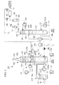
Fig. 1 is an illustration to show a construction of a CO2 recovery unit relating to a first embodiment of the present invention. - {
Fig. 2 }
Figs. 2A and 2B are a perspective view and a section view which respectively show a baffle plate and a cover disposed at an end portion of a return pipe. - {
Fig. 3 }
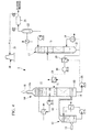
Fig. 3 is an illustration to show a construction of a CO2 recovery unit relating to a second embodiment of the present invention. - {
Fig. 4 }
Fig. 4 is an illustration to show a construction of a CO2 recovery unit of a related art. - Hereinafter, a plurality of embodiments of a carbon dioxide recovery unit of the present invention will be described by the use of
Fig. 1 . - As shown in
Fig. 1 , a CO2 recovery unit 100 is provided with acooling tower 110 for cooling anexhaust gas 10, anabsorption tower 120 for absorbing and recovering CO2 from theexhaust gas 10 by a CO2 absorbing liquid 300, and aregeneration tower 130 for taking out the CO2 from the CO2 absorbing liquid 300 having absorbed the CO2 and for regenerating the CO2 absorbing liquid 300. - In this CO2 recovery unit 100, the
exhaust gas 10 containing CO2 exhausted from an industrial facility, for example, a boiler and a gas turbine is supplied to thecooling tower 110 by a blower (not shown). - The
exhaust gas 10 supplied to thecooling tower 110 is cooled by a coolingwater 310 sprayed into thecooling tower 110 fromnozzles 111. The coolingwater 310 used for cooling theexhaust gas 10 is sent to and cooled by a cooler 113 and then is supplied again to thenozzles 111 of thecooling tower 110 by thepump 112. Here, in the cooler 113, acold water 311 is used as a cold source of the coolingwater 310 to be supplied to thecooling tower 110. - The
exhaust gas 10, which contains the CO2 and is cooled in thecooling tower 110, is sent from atower top portion 110a of thecooling tower 110 to atower bottom portion 120b of theabsorption tower 120 via anexhaust gas line 114. - In the
absorption tower 120, the CO2 absorbing liquid 300 is supplied tonozzles 121 disposed in an upper portion of theabsorption tower 120 and is sprayed downward in theabsorption tower 120 from thenozzles 121. As the CO2 absorbing liquid 300 is used, for example, an amine solution in which alkanolamine is a base component. The CO2 absorbing liquid 300 is brought into countercurrent contact with theexhaust gas 10 rising up from thetower bottom portion 120b while passing through a packedbed 122 disposed in a space below thenozzles 121 in theabsorption tower 120. In this way, the CO2 in theexhaust gas 10 is absorbed by the CO2 absorbing liquid 300, whereby the CO2 is removed from theexhaust gas 10. Here, theexhaust gas 10 from which CO2 is removed is called aclean gas 210. Theclean gas 210 in which CO2 is removed is exhausted from atower top portion 120a of theabsorption tower 120. - Here, when the CO2 is absorbed from the CO2 absorbing liquid 300, the CO2 absorbing liquid 300 is heated and increased in liquid temperature, so that the
clean gas 210 can contain water vapor and the like. In an upper portion of theabsorption tower 120 are disposed amist eliminator 123 andnozzles 124 which are disposed below themist eliminator 123. The water vapor in theclean gas 210 is brought into countercurrent contact with a coolingwater 320 sprayed from thenozzles 124 above the packedbed 122 in the upper portion of theabsorption tower 120, thereby being cooled and condensed. Themist eliminator 123 is disposed above the packedbed 122 and collects mist in theclean gas 210. Outside theabsorption tower 120 are disposed a cooler 127 and apump 126 for recovering a part ofcondensed water 211 by arecovery tank 125 and for circulating the recoveredcondensed water 211 between the cooler 127 and theabsorption tower 120 as a coolingwater 320. - A CO2 absorbing liquid 300R having absorbed the CO2 (hereinafter referred to as "rich solution" in some cases) while passing through the packed
bed 122 of theabsorption tower 120 from above to below is stored in thetower bottom portion 120b. The storedrich solution 300R is fed into theregeneration tower 130 by apump 151 through a liquid feed line L1 for connecting thetower bottom portion 120b of theabsorption tower 120 to an upper portion of theregeneration tower 130. Here, the liquid feed line L1 is provided with aheat exchanger 152. In thisheat exchanger 152, therich solution 300R fed from theabsorption tower 120 into theregeneration tower 130 to be described later exchanges heat with a CO2 absorbing liquid 300L (hereinafter referred to as "lean solution" in some cases) regenerated and cooled by theregeneration tower 130, thereby being heated. - In the
regeneration tower 130,nozzles 131 are disposed in its upper portion and therich solution 300R heated in theheat exchanger 152 is sprayed downward from thenozzles 131. - A packed
bed 132 is disposed below thenozzles 131. In theregeneration tower 130, CO2 is emitted from therich solution 300R by an endothermic reaction caused by a countercurrent contact when therich solution 300R passes through the heated packedbed 132. By the time therich solution 300R reaches atower bottom portion 130b of theregeneration tower 130, the most portion of CO2 is removed from therich solution 300R, whereby therich solution 300R is regenerated as thelean solution 300L. - Further, in the
tower bottom portion 130b of theregeneration tower 130 is provided a circulation path L4 for circulating a portion of thelean solution 300L to the upper portion of thetower bottom portion 130. The circulation path L4 is provided with areboiler 137. Thereboiler 137 is provided with asteam pipe 137a for heating thelean solution 300L. - A portion of the
lean solution 300L in thetower bottom portion 130b is supplied to thereboiler 137 through the circulation path L4 and is heated by a heat exchange with the high-temperature steam passing through thesteam pipe 137a and then is returned into theregeneration tower 130. By the thermal energy of thelean solution 300L heated in this way, CO2 gas is further emitted from thelean solution 300L in thetower bottom portion 130b. Further, since thelean solution 300L is heated, also the packedbed 132 is indirectly heated. As described above, while the gas is in contact with the liquid in the packedbed 132, the CO2 gas is emitted from therich solution 300R. - In this way, the
lean solution 300L having emitted CO2 and regenerated in theregeneration tower 130 is returned to theabsorption tower 120 by apump 153 through a liquid feed line L2 for connecting thetower bottom portion 130b of theregeneration tower 130 to the upper portion of theabsorption tower 120. - The liquid feed line L2 is provided with the
heat exchanger 152 and a water-cooledcooler 154. Thelean solution 300L passing through the liquid feed line L2 exchanges heat with therich solution 300R supplied to theregeneration tower 130 from theabsorption tower 120 in theheat exchanger 152, thereby being cooled, and then exchanges heat with acold water 311 in the water-cooledcooler 154, thereby being cooled to a temperature suitable for absorbing CO2. - A CO2 delivery line (delivery pipe) L3 is connected to the
tower top portion 130a of theregeneration tower 130. The CO2 gas emitted from therich solution 300R in theregeneration tower 130 is exhausted to the outside from the CO2 delivery line L3. - The CO2 delivery line L3 is provided with a cooler 140 using the
cold water 311, a gas-liquid separator 141, and a CO2 compressing device 145. - The CO2 gas emitted from the
regeneration tower 130 through the CO2 delivery line L3 is sufficiently cooled in the cooler 140 and then is fed to the gas-liquid separator 141. - In the gas-
liquid separator 141, acondensed water 330 in the CO2 gas cooled and condensed by the cooler 140 is separated from the CO2 gas. Thecondensed water 330 separated in the gas-liquid separator 141 is returned to the upper portion of theregeneration tower 130 by apump 143. - The returned
condensed water 330 is spayed fromnozzles 135 disposed in the upper portion of theregeneration tower 130 to a condensingportion 136 disposed below thenozzles 135, thereby cooling the CO2 gas and cooling the condensingportion 136 to prevent the emission of an absorbent or the like. - In the CO2 compressing device 145, the CO2 gas having passed through the gas-
liquid separator 141 is compressed. The compressed CO2 gas is fed to a storage process through the CO2 delivery line L3 at the time of an ordinary operation. - In the present embodiment, a CO2 gas return line (return pipe) L5 for feeding the CO2 gas into the
absorption tower 120 is connected to an upstream side and a downstream side of the CO2 compressing device 145 via opening/closing valves (switching parts) 160, 161. - The CO2 gas return line L5 can be disposed in such a way as to communicate with the interior of the
absorption tower 120 at a position P1 above thenozzles 124 for spraying the coolingwater 320 in the upper portion of theabsorption tower 120. - As shown in
Fig. 2 , at the position P1, anend portion 200a of apipe 200 communicating with the interior of theabsorption tower 120 is connected to an outer peripheral side of anopening portion 129 formed in awall body 128 of theabsorption tower 120. Theopening portion 129 is provided with acover 170 and abaffle plate 171. - The
cover 170 is formed nearly in the shape of an inverted letter U and is formed of: an uppercurved wall portion 170a disposed along anupper half portion 129a of thecircular opening portion 129; and lowerside wall portions curved wall portion 170a positioned on both sides of amaximum width portion 129b of theopening portion 129. - At the position P1, the cooling
water 320 flows down. By providing theopening portion 129 formed at the position P1 with thecover 170, it is possible to prevent thecooling water 320 from flowing into thepipe 200 from theopening portion 129. - The
baffle plate 171 is disposed in such a way as to block alower portion 129c of theopening portion 129 and is constructed of acurved portion 171a formed along an inner peripheral portion of theopening portion 129 and a straight portion 17ab for connecting both end portions of thecurved portion 171a, and thecurved portion 171a is welded to an inner peripheral surface of thelower portion 129c of theopening portion 129. - By providing the
opening portion 129 formed at the position P1 with thebaffle plate 171, it is possible to prevent thecooling water 320 splashed from below from flowing into thepipe 200 from theopening portion 129. - Further, as shown in
Fig. 1 , in the present embodiment, the CO2 gas return line L5 is branched in the middle and a branched drain line (return pipe) L6 is disposed in such a way as to communicate with the interior of theabsorption tower 120 at a position P3 above a portion in which therich solution 300R is stored in thetower bottom portion 120b of theabsorption tower 120. - The drain line L6 is provided with a
drain trap 165. Thedrain trap 165 recovers a liquid component contained in the CO2 gas fed from the CO2 compressing device 145. - The opening/
closing valve 160 is operated in such a way as to be opened by a control part (not shown) when a gas pressure detected by a pressure sensor (not shown) on the upstream side of the CO2 compressing device 145 is larger than a specified reference value. - The opening/
closing valve 161 is operated in such a way as to be opened by a control part (not shown) when a gas pressure detected by a pressure sensor (not shown) on the downstream side of the CO2 compressing device 145 is larger than a specified reference value. - In this way, when the gas pressure is larger than the specified reference value on the upstream side or the downstream side of the CO2 compressing device 145, the CO2 gas is returned to the
absorption tower 120 through the CO2 gas return line L5 and the drain line L6 and is mixed with theexhaust gas 10 in theabsorption tower 120. - According to the construction described above, the CO2 is absorbed and recovered from the
exhaust gas 10 by the CO2 absorbing liquid 300 in theabsorption tower 120, and the CO2 is taken out of the CO2 absorbing liquid 300 in theregeneration tower 130. At the time of the ordinary operation, the taken-out CO2 is delivered to the storage process. Further, when the CO2 recovery unit 100 and the CO2 compressing device 145 are activated, if some kind of trouble is caused on the storage process side and hence the storage process cannot receive the CO2, the CO2 gas is fed into theabsorption tower 120 through the CO2 gas return line L5. In this way, the CO2 gas can be mixed with the exhaust gas 10 (clean gas 210) and can be diffused into the atmosphere along with theclean gas 210. - This can eliminate the need for installing a vent stack and a duct to the vent stack and hence can greatly reduce an installation cost and an operation cost.
- Further, since the CO2 gas has a larger specific gravity as compared to the atmosphere, the CO2 gas is hard to diffuse and hence is likely to collect in a lower portion as is in a place into which the CO2 gas diffuses. On the other hand, when the CO2 gas is mixed with the
exhaust gas 10, the concentration of CO2 in a mixed gas of the CO2 gas and theexhaust gas 10 is decreased, so that when the mixed gas is diffused into the atmosphere from thetower top portion 120a of theabsorption tower 120, the diffusibility of the CO2 can be improved. - Still further, the CO2 gas returned to the
absorption tower 120 from the drain line L6 is in contact with theexhaust gas 10 in theabsorption tower 120 for a long time and hence can be well mixed with theexhaust gas 10, whereby the diffusibility of the CO2 gas can be improved more reliably. - In this regard, in the embodiment described above, the CO2 gas return line L5 is disposed in such a way as to communicate with the interior of the
absorption tower 120 at the position P1 above thenozzles 124 disposed in the upper portion of theabsorption tower 120. However, the position in which the CO2 gas return line L5 is disposed is not limited to the position P1, and the CO2 gas return line L5 may be disposed at the other position. - For example, the CO2 gas return line L5 can be also disposed in such a way as to communicate with the interior of the
absorption tower 120 above themist eliminator 123 in theabsorption tower 120. - Hereinafter, another embodiment of a carbon dioxide recovery unit relating to the present invention will be described.
- Here, a second embodiment to be shown below is different from the first embodiment only in a position in which the CO2 gas return line L5 is connected to the
absorption tower 120, so that the descriptions of the constructions common to the embodiment described above will be omitted. - As shown in
Fig. 3 , in the present embodiment, the CO2 gas return line L5 can be disposed in such a way as to communicate with the interior of theabsorption tower 120 at a position P2 facing therecovery tank 125 for recovering a part of coolingwater 320 sprayed from thenozzles 124 disposed below themist eliminator 123 and a part ofcondensed water 211 dropped from themist eliminator 123. - As shown in
Fig. 2 , theopening portion 129 formed at the position P2 can be also provided with thecover 170 and thebaffle plate 171. - In this construction, the CO2 gas is blown into water (recovered cooling
water 320 and condensed water 211) in therecovery tank 125 from the CO2 gas return line L5, whereby a carbonated water is produced and the pH of coolingwater 320 is reduced. Then, the carbonated water is sprayed into theabsorption tower 120 as the coolingwater 320 from thenozzles 124. Since the carbonated water is acid, when the carbonated water is brought into contact with an alkali amine vapor or mist of the CO2 absorbing liquid 300, the amine vapor or mist can be captured and neutralized. - The
clean gas 210 in which CO2 is removed is exhausted from thetower top portion 120a of theabsorption tower 120, and a part of amine solution is mixed into theclean gas 210. Hence, the employment of the construction described above can decrease pH of the coolingwater 320 and hence can reduce the amine emission. - Here, the constructions shown in
Fig. 1 to Fig. 4 may be combined with each other as required. - Further, the specific constructions of the
regeneration tower 130 and theabsorption tower 120 and the constructions of the other accessory facilities are not limited to the constructions described above but may be changed to the other constructions as required. - In addition, the constructions described above can be modified and omitted as required within the scope of the gist of the present invention.
-
- 10
- exhaust gas
- 100
- CO2 recovery unit
- 110
- cooling tower
- 111
- nozzle
- 112
- pump
- 113
- cooler
- 114
- exhaust gas line
- 120
- absorption tower
- 120a
- tower top portion
- 120b
- tower bottom portion
- 121
- nozzle
- 122
- packed bed
- 123
- mist eliminator
- 124
- nozzle
- 125
- recovery tank
- 126
- pump
- 127
- cooler
- 128
- wall body
- 129
- opening portion
- 130
- regeneration tower
- 131
- nozzle
- 132
- packed bed
- 135
- nozzle
- 136
- condensing portion
- 137
- reboiler
- 140
- cooler
- 141
- gas-liquid separator
- 143
- pump
- 145
- compressing device
- 151
- pump
- 152
- heat exchanger
- 153
- pump
- 154
- water-cooled cooler
- 160, 161
- opening/closing valve (switching part)
- 165
- drain trap
- 170
- cover
- 171
- baffle plate
- 200
- pipe
- 200a
- end portion
- 210
- clean gas
- 211
- condensed water
- 300
- CO2 absorbing liquid
- 300R
- rich solution
- 300L
- lean solution
- 310
- cooling water
- 311
- cold water
- 320
- cooling water
- 330
- condensed water
- L1
- CO2 feed line
- L2
- CO2 feed line
- L3
- CO2 delivery line (delivery pipe)
- L4
- circulation path
- L5
- CO2 return line (return pipe)
- L6
- drain line (return pipe)
Claims (8)
- A carbon dioxide recovery unit comprising:an absorption tower for bringing a CO2 absorbing liquid of absorbing CO2 into contact with an exhaust gas exhausted from a facility for burning fuel to thereby absorb the CO2 contained in the exhaust gas;a regeneration tower for emitting the CO2 from the CO2 absorbing liquid having absorbed the CO2 in the absorption tower and for regenerating the CO2 absorbing liquid;a delivery pipe for delivering the CO2 emitted in the regeneration tower to the outside;a return pipe for feeding the CO2 emitted in the regeneration tower to the absorption tower to thereby mix the CO2 with a clean gas made by removing the CO2 from the exhaust gas; anda switching part for switching a destination part to which the CO2 is delivered from the regeneration tower.
- A carbon dioxide recovery unit according to claim 1, wherein when a pressure of the CO2 in the delivery pipe is a specified level or more, the switching part switches a destination part to which the CO2 is delivered from the regeneration tower from the delivery pipe to the return pipe.
- A carbon dioxide recovery unit according to claim 1,
wherein the return pipe feeds the CO2 emitted in the regeneration tower into the absorption tower on a downstream side in a direction of flow of the exhaust gas to a region in which the CO2 absorbing liquid is brought into contact with the exhaust gas in the absorption tower. - A carbon dioxide recovery unit according to claim 1, wherein the return pipe feeds the CO2 emitted in the regeneration tower into a cooling water for cleaning and cooling the clean gas.
- A carbon dioxide recovery unit according to claim 4, wherein the return pipe feeds the CO2 emitted in the regeneration tower into a recovery tank for recovering the cooling water in order to circulate the cooling water in the absorption tower.
- A carbon dioxide recovery unit according to claim 1, wherein an upper portion of an opening portion of the absorption tower having an end portion of the return pipe connected thereto is provided with a cover protruding inward of the absorption tower in order to prevent a cooling water from flowing into the return pipe from the opening portion, the cooling water flowing down from above in the absorption tower and cleaning and cooling the clean gas.
- A carbon dioxide recovery unit according to claim 1, wherein a lower portion of an opening portion of the absorption tower having an end portion of the return pipe connected thereto is provided with a baffle plate for blocking a part of a lower portion of the opening portion in order to prevent a cooling water from flowing into the return pipe from the opening portion, the cooling water flowing down from above in the absorption tower and cleaning and cooling the clean gas.
- A carbon dioxide recovery unit according to claim 1, wherein the return pipe is provided with a drain trap for recovering a liquid component contained in the CO2 fed from the regeneration tower and a cooling water flowing into the return pipe from the absorption tower and for cleaning and cooling the clean gas.
Applications Claiming Priority (2)
| Application Number | Priority Date | Filing Date | Title |
|---|---|---|---|
| US13/623,495 US8961664B2 (en) | 2012-09-20 | 2012-09-20 | Carbon dioxide recovery device |
| PCT/JP2013/074767 WO2014046018A1 (en) | 2012-09-20 | 2013-09-12 | Carbon dioxide recovery device |
Publications (3)
| Publication Number | Publication Date |
|---|---|
| EP2898940A1 true EP2898940A1 (en) | 2015-07-29 |
| EP2898940A4 EP2898940A4 (en) | 2016-05-18 |
| EP2898940B1 EP2898940B1 (en) | 2017-06-21 |
Family
ID=50273105
Family Applications (1)
| Application Number | Title | Priority Date | Filing Date |
|---|---|---|---|
| EP13838143.9A Active EP2898940B1 (en) | 2012-09-20 | 2013-09-12 | Carbon dioxide recovery device |
Country Status (6)
| Country | Link |
|---|---|
| US (1) | US8961664B2 (en) |
| EP (1) | EP2898940B1 (en) |
| JP (1) | JP5972985B2 (en) |
| AU (1) | AU2013319191B2 (en) |
| CA (1) | CA2883832C (en) |
| WO (1) | WO2014046018A1 (en) |
Families Citing this family (15)
| Publication number | Priority date | Publication date | Assignee | Title |
|---|---|---|---|---|
| US9616374B2 (en) * | 2013-12-14 | 2017-04-11 | Millenium Synthfuels Corporation | Multi-stage temperature based separation of gas impurities |
| JP2016215105A (en) * | 2015-05-18 | 2016-12-22 | 株式会社東芝 | Carbon dioxide recovery device and carbon dioxide recovery method |
| US10493397B2 (en) | 2015-07-14 | 2019-12-03 | John E. Stauffer | Carbon dioxide recovery |
| US10293304B2 (en) | 2015-07-14 | 2019-05-21 | John E. Stauffer | Carbon dioxide recovery using an absorption column in combination with osmotic filters |
| US10040737B2 (en) | 2015-07-14 | 2018-08-07 | John E. Stauffer | Methanol production from methane and carbon dioxide |
| CN109453621B (en) * | 2018-12-21 | 2024-06-25 | 江苏格陵兰传热科技有限公司 | Waste gas recycling energy-saving device |
| GB2594043A (en) | 2020-03-30 | 2021-10-20 | Equinor Energy As | System for offshore carbon dioxide capture |
| JP7524086B2 (en) * | 2021-01-15 | 2024-07-29 | 株式会社東芝 | Carbon dioxide capture system and method for operating the carbon dioxide capture system |
| KR102592261B1 (en) * | 2021-06-17 | 2023-10-23 | 주식회사 파나시아 | Carbon dioxide Capture and Sequestration System |
| KR102592257B1 (en) * | 2021-06-17 | 2023-10-23 | 주식회사 파나시아 | Carbon dioxide Capture and Sequestration System |
| KR102592249B1 (en) * | 2021-06-17 | 2023-10-23 | 주식회사 파나시아 | Carbon dioxide Capture and Sequestration System |
| KR102592265B1 (en) * | 2021-06-17 | 2023-10-23 | 주식회사 파나시아 | Carbon dioxide Capture and Sequestration System |
| CN117398833B (en) * | 2023-12-12 | 2024-04-05 | 成都赢纳环保科技有限公司 | Industrial waste gas treatment equipment |
| CN119158382B (en) * | 2024-09-13 | 2025-09-12 | 中国华能集团清洁能源技术研究院有限公司 | Start-stop and canned coupling method, device, equipment and storage medium for capturing carbon dioxide |
| CN118807413B (en) * | 2024-09-19 | 2024-11-15 | 中国华能集团清洁能源技术研究院有限公司 | Regeneration tower and regeneration system |
Family Cites Families (14)
| Publication number | Priority date | Publication date | Assignee | Title |
|---|---|---|---|---|
| US3438734A (en) * | 1967-05-15 | 1969-04-15 | North American Rockwell | Sulfur production using carbon oxide regenerant |
| JP2786560B2 (en) | 1992-01-17 | 1998-08-13 | 関西電力株式会社 | Apparatus and method for removing carbon dioxide from flue gas |
| US5378442A (en) * | 1992-01-17 | 1995-01-03 | The Kansai Electric Power Co., Inc. | Method for treating combustion exhaust gas |
| JP2786559B2 (en) | 1992-01-17 | 1998-08-13 | 関西電力株式会社 | Method for recovering carbon dioxide from flue gas |
| US6689332B1 (en) * | 1992-09-16 | 2004-02-10 | The Kansai Electric Power Co, Inc. | Process for removing carbon dioxide from combustion gases |
| PE20071048A1 (en) * | 2005-12-12 | 2007-10-18 | Basf Ag | PROCESS FOR THE RECOVERY OF CARBON DIOXIDE |
| US20090282977A1 (en) | 2008-05-14 | 2009-11-19 | Alstom Technology Ltd | Gas purification system having provisions for co2 injection of wash water |
| JP5751743B2 (en) | 2009-03-09 | 2015-07-22 | 三菱重工業株式会社 | Exhaust gas treatment apparatus and exhaust gas treatment method |
| US8007570B2 (en) * | 2009-03-11 | 2011-08-30 | General Electric Company | Systems, methods, and apparatus for capturing CO2 using a solvent |
| US20110146489A1 (en) | 2009-12-17 | 2011-06-23 | Alstom Technology Ltd | Ammonia removal, following removal of co2, from a gas stream |
| JP5576879B2 (en) | 2009-12-28 | 2014-08-20 | バブコック日立株式会社 | Carbon dioxide absorption liquid and recovery method |
| DE102010013729A1 (en) | 2010-03-31 | 2011-10-06 | Siemens Aktiengesellschaft | Method and apparatus for separating carbon dioxide from an exhaust gas of a fossil-fired power plant |
| JP5351816B2 (en) | 2010-04-08 | 2013-11-27 | 三菱重工業株式会社 | Apparatus and method for recovering carbon dioxide in exhaust gas |
| US9133407B2 (en) * | 2011-02-25 | 2015-09-15 | Alstom Technology Ltd | Systems and processes for removing volatile degradation products produced in gas purification |
-
2012
- 2012-09-20 US US13/623,495 patent/US8961664B2/en active Active
-
2013
- 2013-09-12 WO PCT/JP2013/074767 patent/WO2014046018A1/en not_active Ceased
- 2013-09-12 JP JP2014536819A patent/JP5972985B2/en active Active
- 2013-09-12 CA CA2883832A patent/CA2883832C/en active Active
- 2013-09-12 EP EP13838143.9A patent/EP2898940B1/en active Active
- 2013-09-12 AU AU2013319191A patent/AU2013319191B2/en active Active
Also Published As
| Publication number | Publication date |
|---|---|
| US20140076166A1 (en) | 2014-03-20 |
| JP5972985B2 (en) | 2016-08-17 |
| AU2013319191A1 (en) | 2015-03-19 |
| JPWO2014046018A1 (en) | 2016-08-18 |
| WO2014046018A1 (en) | 2014-03-27 |
| CA2883832A1 (en) | 2014-03-27 |
| US8961664B2 (en) | 2015-02-24 |
| AU2013319191B2 (en) | 2016-07-07 |
| EP2898940B1 (en) | 2017-06-21 |
| CA2883832C (en) | 2017-03-28 |
| EP2898940A4 (en) | 2016-05-18 |
Similar Documents
| Publication | Publication Date | Title |
|---|---|---|
| EP2898940B1 (en) | Carbon dioxide recovery device | |
| JP7577776B2 (en) | Carbon Dioxide Capture System | |
| US7918926B2 (en) | CO2 recovery system and method | |
| TWI466713B (en) | Gas treatment process and system | |
| US9399939B2 (en) | Combustion exhaust gas treatment system and method of treating combustion exhaust gas | |
| US20110033359A1 (en) | Cooled naoh flue gas scrubbing prior to co2 removal | |
| EP2230000A1 (en) | Flue gas treatment system and method using ammonia solution | |
| JP2008307520A (en) | Co2 or h2s removal system, co2 or h2s removal method | |
| US20190001261A1 (en) | Co2 recovery device and co2 recovery method | |
| US20130192470A1 (en) | Co2 recovery system | |
| US20230372864A1 (en) | Apparatus for reducing greenhouse gas emission in vessel and vessel including the same | |
| JP2012528707A (en) | Cleaning tower and associated flue gas cleaning equipment | |
| US10213727B2 (en) | CO2 recovery device and CO2 recovery method | |
| WO2020202804A1 (en) | Cooling absorption tower, co2 recovery device comprising same, and co2 recovery method | |
| EP2644254B1 (en) | Scrubber for cleaning a process gas and recovering heat | |
| US20230372867A1 (en) | Apparatus for reducing greenhouse gas emission in vessel and vessel including the same | |
| JP2011125824A (en) | System for separating/recovering carbon dioxide | |
| KR20240159352A (en) | Exhaust gas treatment system | |
| CN118807413B (en) | Regeneration tower and regeneration system | |
| KR20240159248A (en) | Exhaust gas treatment system | |
| KR20220074349A (en) | Carbon dioxide absorber |
Legal Events
| Date | Code | Title | Description |
|---|---|---|---|
| PUAI | Public reference made under article 153(3) epc to a published international application that has entered the european phase |
Free format text: ORIGINAL CODE: 0009012 |
|
| 17P | Request for examination filed |
Effective date: 20150310 |
|
| AK | Designated contracting states |
Kind code of ref document: A1 Designated state(s): AL AT BE BG CH CY CZ DE DK EE ES FI FR GB GR HR HU IE IS IT LI LT LU LV MC MK MT NL NO PL PT RO RS SE SI SK SM TR |
|
| AX | Request for extension of the european patent |
Extension state: BA ME |
|
| DAX | Request for extension of the european patent (deleted) | ||
| RA4 | Supplementary search report drawn up and despatched (corrected) |
Effective date: 20160418 |
|
| RIC1 | Information provided on ipc code assigned before grant |
Ipc: B01D 53/62 20060101AFI20160412BHEP Ipc: F23J 15/04 20060101ALI20160412BHEP Ipc: C01B 31/20 20060101ALI20160412BHEP Ipc: B01D 53/14 20060101ALI20160412BHEP |
|
| GRAP | Despatch of communication of intention to grant a patent |
Free format text: ORIGINAL CODE: EPIDOSNIGR1 |
|
| INTG | Intention to grant announced |
Effective date: 20161207 |
|
| GRAJ | Information related to disapproval of communication of intention to grant by the applicant or resumption of examination proceedings by the epo deleted |
Free format text: ORIGINAL CODE: EPIDOSDIGR1 |
|
| GRAR | Information related to intention to grant a patent recorded |
Free format text: ORIGINAL CODE: EPIDOSNIGR71 |
|
| GRAS | Grant fee paid |
Free format text: ORIGINAL CODE: EPIDOSNIGR3 |
|
| INTC | Intention to grant announced (deleted) | ||
| GRAA | (expected) grant |
Free format text: ORIGINAL CODE: 0009210 |
|
| RIC1 | Information provided on ipc code assigned before grant |
Ipc: B01D 53/14 20060101ALI20170419BHEP Ipc: F23J 15/04 20060101ALI20170419BHEP Ipc: B01D 53/62 20060101AFI20170419BHEP |
|
| AK | Designated contracting states |
Kind code of ref document: B1 Designated state(s): AL AT BE BG CH CY CZ DE DK EE ES FI FR GB GR HR HU IE IS IT LI LT LU LV MC MK MT NL NO PL PT RO RS SE SI SK SM TR |
|
| INTG | Intention to grant announced |
Effective date: 20170516 |
|
| REG | Reference to a national code |
Ref country code: GB Ref legal event code: FG4D |
|
| REG | Reference to a national code |
Ref country code: CH Ref legal event code: EP |
|
| REG | Reference to a national code |
Ref country code: IE Ref legal event code: FG4D |
|
| REG | Reference to a national code |
Ref country code: AT Ref legal event code: REF Ref document number: 902421 Country of ref document: AT Kind code of ref document: T Effective date: 20170715 |
|
| REG | Reference to a national code |
Ref country code: DE Ref legal event code: R096 Ref document number: 602013022679 Country of ref document: DE |
|
| REG | Reference to a national code |
Ref country code: DE Ref legal event code: R082 Ref document number: 602013022679 Country of ref document: DE Representative=s name: KOHLER SCHMID MOEBUS PATENTANWAELTE PARTNERSCH, DE |
|
| REG | Reference to a national code |
Ref country code: NL Ref legal event code: FP |
|
| PG25 | Lapsed in a contracting state [announced via postgrant information from national office to epo] |
Ref country code: HR Free format text: LAPSE BECAUSE OF FAILURE TO SUBMIT A TRANSLATION OF THE DESCRIPTION OR TO PAY THE FEE WITHIN THE PRESCRIBED TIME-LIMIT Effective date: 20170621 Ref country code: FI Free format text: LAPSE BECAUSE OF FAILURE TO SUBMIT A TRANSLATION OF THE DESCRIPTION OR TO PAY THE FEE WITHIN THE PRESCRIBED TIME-LIMIT Effective date: 20170621 Ref country code: LT Free format text: LAPSE BECAUSE OF FAILURE TO SUBMIT A TRANSLATION OF THE DESCRIPTION OR TO PAY THE FEE WITHIN THE PRESCRIBED TIME-LIMIT Effective date: 20170621 Ref country code: GR Free format text: LAPSE BECAUSE OF FAILURE TO SUBMIT A TRANSLATION OF THE DESCRIPTION OR TO PAY THE FEE WITHIN THE PRESCRIBED TIME-LIMIT Effective date: 20170922 |
|
| REG | Reference to a national code |
Ref country code: LT Ref legal event code: MG4D |
|
| REG | Reference to a national code |
Ref country code: AT Ref legal event code: MK05 Ref document number: 902421 Country of ref document: AT Kind code of ref document: T Effective date: 20170621 |
|
| PG25 | Lapsed in a contracting state [announced via postgrant information from national office to epo] |
Ref country code: RS Free format text: LAPSE BECAUSE OF FAILURE TO SUBMIT A TRANSLATION OF THE DESCRIPTION OR TO PAY THE FEE WITHIN THE PRESCRIBED TIME-LIMIT Effective date: 20170621 Ref country code: BG Free format text: LAPSE BECAUSE OF FAILURE TO SUBMIT A TRANSLATION OF THE DESCRIPTION OR TO PAY THE FEE WITHIN THE PRESCRIBED TIME-LIMIT Effective date: 20170921 Ref country code: LV Free format text: LAPSE BECAUSE OF FAILURE TO SUBMIT A TRANSLATION OF THE DESCRIPTION OR TO PAY THE FEE WITHIN THE PRESCRIBED TIME-LIMIT Effective date: 20170621 Ref country code: SE Free format text: LAPSE BECAUSE OF FAILURE TO SUBMIT A TRANSLATION OF THE DESCRIPTION OR TO PAY THE FEE WITHIN THE PRESCRIBED TIME-LIMIT Effective date: 20170621 |
|
| REG | Reference to a national code |
Ref country code: NO Ref legal event code: T2 Effective date: 20170621 |
|
| PG25 | Lapsed in a contracting state [announced via postgrant information from national office to epo] |
Ref country code: SK Free format text: LAPSE BECAUSE OF FAILURE TO SUBMIT A TRANSLATION OF THE DESCRIPTION OR TO PAY THE FEE WITHIN THE PRESCRIBED TIME-LIMIT Effective date: 20170621 Ref country code: CZ Free format text: LAPSE BECAUSE OF FAILURE TO SUBMIT A TRANSLATION OF THE DESCRIPTION OR TO PAY THE FEE WITHIN THE PRESCRIBED TIME-LIMIT Effective date: 20170621 Ref country code: RO Free format text: LAPSE BECAUSE OF FAILURE TO SUBMIT A TRANSLATION OF THE DESCRIPTION OR TO PAY THE FEE WITHIN THE PRESCRIBED TIME-LIMIT Effective date: 20170621 Ref country code: AT Free format text: LAPSE BECAUSE OF FAILURE TO SUBMIT A TRANSLATION OF THE DESCRIPTION OR TO PAY THE FEE WITHIN THE PRESCRIBED TIME-LIMIT Effective date: 20170621 Ref country code: EE Free format text: LAPSE BECAUSE OF FAILURE TO SUBMIT A TRANSLATION OF THE DESCRIPTION OR TO PAY THE FEE WITHIN THE PRESCRIBED TIME-LIMIT Effective date: 20170621 |
|
| PG25 | Lapsed in a contracting state [announced via postgrant information from national office to epo] |
Ref country code: ES Free format text: LAPSE BECAUSE OF FAILURE TO SUBMIT A TRANSLATION OF THE DESCRIPTION OR TO PAY THE FEE WITHIN THE PRESCRIBED TIME-LIMIT Effective date: 20170621 Ref country code: SM Free format text: LAPSE BECAUSE OF FAILURE TO SUBMIT A TRANSLATION OF THE DESCRIPTION OR TO PAY THE FEE WITHIN THE PRESCRIBED TIME-LIMIT Effective date: 20170621 Ref country code: IS Free format text: LAPSE BECAUSE OF FAILURE TO SUBMIT A TRANSLATION OF THE DESCRIPTION OR TO PAY THE FEE WITHIN THE PRESCRIBED TIME-LIMIT Effective date: 20171021 Ref country code: PL Free format text: LAPSE BECAUSE OF FAILURE TO SUBMIT A TRANSLATION OF THE DESCRIPTION OR TO PAY THE FEE WITHIN THE PRESCRIBED TIME-LIMIT Effective date: 20170621 |
|
| REG | Reference to a national code |
Ref country code: DE Ref legal event code: R097 Ref document number: 602013022679 Country of ref document: DE |
|
| PLBE | No opposition filed within time limit |
Free format text: ORIGINAL CODE: 0009261 |
|
| STAA | Information on the status of an ep patent application or granted ep patent |
Free format text: STATUS: NO OPPOSITION FILED WITHIN TIME LIMIT |
|
| PG25 | Lapsed in a contracting state [announced via postgrant information from national office to epo] |
Ref country code: DK Free format text: LAPSE BECAUSE OF FAILURE TO SUBMIT A TRANSLATION OF THE DESCRIPTION OR TO PAY THE FEE WITHIN THE PRESCRIBED TIME-LIMIT Effective date: 20170621 |
|
| REG | Reference to a national code |
Ref country code: CH Ref legal event code: PL |
|
| 26N | No opposition filed |
Effective date: 20180322 |
|
| PG25 | Lapsed in a contracting state [announced via postgrant information from national office to epo] |
Ref country code: MC Free format text: LAPSE BECAUSE OF FAILURE TO SUBMIT A TRANSLATION OF THE DESCRIPTION OR TO PAY THE FEE WITHIN THE PRESCRIBED TIME-LIMIT Effective date: 20170621 |
|
| REG | Reference to a national code |
Ref country code: IE Ref legal event code: MM4A |
|
| REG | Reference to a national code |
Ref country code: BE Ref legal event code: MM Effective date: 20170930 |
|
| PG25 | Lapsed in a contracting state [announced via postgrant information from national office to epo] |
Ref country code: LU Free format text: LAPSE BECAUSE OF NON-PAYMENT OF DUE FEES Effective date: 20170912 |
|
| REG | Reference to a national code |
Ref country code: FR Ref legal event code: ST Effective date: 20180531 |
|
| REG | Reference to a national code |
Ref country code: DE Ref legal event code: R082 Ref document number: 602013022679 Country of ref document: DE Representative=s name: KOHLER SCHMID MOEBUS PATENTANWAELTE PARTNERSCH, DE Ref country code: DE Ref legal event code: R081 Ref document number: 602013022679 Country of ref document: DE Owner name: MITSUBISHI HEAVY INDUSTRIES ENGINEERING, LTD.,, JP Free format text: FORMER OWNER: MITSUBISHI HEAVY INDUSTRIES, LTD., TOKYO, JP |
|
| REG | Reference to a national code |
Ref country code: NO Ref legal event code: CHAD Owner name: MITSUBISHI HEAVY INDUSTRIES ENGINEERING, JP |
|
| REG | Reference to a national code |
Ref country code: GB Ref legal event code: 732E Free format text: REGISTERED BETWEEN 20180628 AND 20180706 |
|
| PG25 | Lapsed in a contracting state [announced via postgrant information from national office to epo] |
Ref country code: IE Free format text: LAPSE BECAUSE OF NON-PAYMENT OF DUE FEES Effective date: 20170912 Ref country code: CH Free format text: LAPSE BECAUSE OF NON-PAYMENT OF DUE FEES Effective date: 20170930 Ref country code: LI Free format text: LAPSE BECAUSE OF NON-PAYMENT OF DUE FEES Effective date: 20170930 |
|
| PG25 | Lapsed in a contracting state [announced via postgrant information from national office to epo] |
Ref country code: BE Free format text: LAPSE BECAUSE OF NON-PAYMENT OF DUE FEES Effective date: 20170930 Ref country code: SI Free format text: LAPSE BECAUSE OF FAILURE TO SUBMIT A TRANSLATION OF THE DESCRIPTION OR TO PAY THE FEE WITHIN THE PRESCRIBED TIME-LIMIT Effective date: 20170621 Ref country code: FR Free format text: LAPSE BECAUSE OF NON-PAYMENT OF DUE FEES Effective date: 20171002 |
|
| PG25 | Lapsed in a contracting state [announced via postgrant information from national office to epo] |
Ref country code: MT Free format text: LAPSE BECAUSE OF NON-PAYMENT OF DUE FEES Effective date: 20170912 |
|
| REG | Reference to a national code |
Ref country code: NL Ref legal event code: PD Owner name: MITSUBISHI HEAVY INDUSTRIES ENGINEERING, LTD.; JP Free format text: DETAILS ASSIGNMENT: CHANGE OF OWNER(S), ASSIGNMENT; FORMER OWNER NAME: MITSUBISHI HEAVY INDUSTRIES, LTD. Effective date: 20180816 |
|
| PG25 | Lapsed in a contracting state [announced via postgrant information from national office to epo] |
Ref country code: HU Free format text: LAPSE BECAUSE OF FAILURE TO SUBMIT A TRANSLATION OF THE DESCRIPTION OR TO PAY THE FEE WITHIN THE PRESCRIBED TIME-LIMIT; INVALID AB INITIO Effective date: 20130912 |
|
| PG25 | Lapsed in a contracting state [announced via postgrant information from national office to epo] |
Ref country code: CY Free format text: LAPSE BECAUSE OF FAILURE TO SUBMIT A TRANSLATION OF THE DESCRIPTION OR TO PAY THE FEE WITHIN THE PRESCRIBED TIME-LIMIT Effective date: 20170621 |
|
| PG25 | Lapsed in a contracting state [announced via postgrant information from national office to epo] |
Ref country code: MK Free format text: LAPSE BECAUSE OF FAILURE TO SUBMIT A TRANSLATION OF THE DESCRIPTION OR TO PAY THE FEE WITHIN THE PRESCRIBED TIME-LIMIT Effective date: 20170621 |
|
| PG25 | Lapsed in a contracting state [announced via postgrant information from national office to epo] |
Ref country code: TR Free format text: LAPSE BECAUSE OF FAILURE TO SUBMIT A TRANSLATION OF THE DESCRIPTION OR TO PAY THE FEE WITHIN THE PRESCRIBED TIME-LIMIT Effective date: 20170621 |
|
| PG25 | Lapsed in a contracting state [announced via postgrant information from national office to epo] |
Ref country code: PT Free format text: LAPSE BECAUSE OF FAILURE TO SUBMIT A TRANSLATION OF THE DESCRIPTION OR TO PAY THE FEE WITHIN THE PRESCRIBED TIME-LIMIT Effective date: 20170621 |
|
| PG25 | Lapsed in a contracting state [announced via postgrant information from national office to epo] |
Ref country code: AL Free format text: LAPSE BECAUSE OF FAILURE TO SUBMIT A TRANSLATION OF THE DESCRIPTION OR TO PAY THE FEE WITHIN THE PRESCRIBED TIME-LIMIT Effective date: 20170621 |
|
| P01 | Opt-out of the competence of the unified patent court (upc) registered |
Effective date: 20230522 |
|
| REG | Reference to a national code |
Ref country code: DE Ref legal event code: R081 Ref document number: 602013022679 Country of ref document: DE Owner name: MITSUBISHI HEAVY INDUSTRIES, LTD., JP Free format text: FORMER OWNER: MITSUBISHI HEAVY INDUSTRIES ENGINEERING, LTD., YOKOHAMA-SHI, KANAGAWA, JP |
|
| REG | Reference to a national code |
Ref country code: DE Ref legal event code: R081 Ref document number: 602013022679 Country of ref document: DE Owner name: MITSUBISHI HEAVY INDUSTRIES, LTD., JP Free format text: FORMER OWNER: MHI ENGINEERING, LTD., YOKOHAMA-SHI, KANAGAWA, JP |
|
| REG | Reference to a national code |
Ref country code: NL Ref legal event code: PD Owner name: MITSUBISHI HEAVY INDUSTRIES, LTD.; JP Free format text: DETAILS ASSIGNMENT: CHANGE OF OWNER(S), ASSIGNMENT; FORMER OWNER NAME: MITSUBISHI HEAVY INDUSTRIES, LTD. Effective date: 20231206 Ref country code: NL Ref legal event code: HC Owner name: MHI ENGINEERING, LTD.; JP Free format text: DETAILS ASSIGNMENT: CHANGE OF OWNER(S), CHANGE OF OWNER(S) NAME; FORMER OWNER NAME: MITSUBISHI HEAVY INDUSTRIES ENGINEERING, LTD. Effective date: 20231206 |
|
| REG | Reference to a national code |
Ref country code: GB Ref legal event code: 732E Free format text: REGISTERED BETWEEN 20240404 AND 20240410 |
|
| PGFP | Annual fee paid to national office [announced via postgrant information from national office to epo] |
Ref country code: NL Payment date: 20250814 Year of fee payment: 13 |
|
| PGFP | Annual fee paid to national office [announced via postgrant information from national office to epo] |
Ref country code: DE Payment date: 20250730 Year of fee payment: 13 |
|
| PGFP | Annual fee paid to national office [announced via postgrant information from national office to epo] |
Ref country code: NO Payment date: 20250909 Year of fee payment: 13 |
|
| PGFP | Annual fee paid to national office [announced via postgrant information from national office to epo] |
Ref country code: IT Payment date: 20250825 Year of fee payment: 13 |
|
| PGFP | Annual fee paid to national office [announced via postgrant information from national office to epo] |
Ref country code: GB Payment date: 20250731 Year of fee payment: 13 |