EP2898771A1 - Fishing reel - Google Patents
Fishing reel Download PDFInfo
- Publication number
- EP2898771A1 EP2898771A1 EP14200133.8A EP14200133A EP2898771A1 EP 2898771 A1 EP2898771 A1 EP 2898771A1 EP 14200133 A EP14200133 A EP 14200133A EP 2898771 A1 EP2898771 A1 EP 2898771A1
- Authority
- EP
- European Patent Office
- Prior art keywords
- fitting recess
- component member
- groove
- reel
- fishing reel
- Prior art date
- Legal status (The legal status is an assumption and is not a legal conclusion. Google has not performed a legal analysis and makes no representation as to the accuracy of the status listed.)
- Granted
Links
Images


Classifications
-
- A—HUMAN NECESSITIES
- A01—AGRICULTURE; FORESTRY; ANIMAL HUSBANDRY; HUNTING; TRAPPING; FISHING
- A01K—ANIMAL HUSBANDRY; AVICULTURE; APICULTURE; PISCICULTURE; FISHING; REARING OR BREEDING ANIMALS, NOT OTHERWISE PROVIDED FOR; NEW BREEDS OF ANIMALS
- A01K89/00—Reels
- A01K89/01—Reels with pick-up, i.e. with the guiding member rotating and the spool not rotating during normal retrieval of the line
-
- A—HUMAN NECESSITIES
- A01—AGRICULTURE; FORESTRY; ANIMAL HUSBANDRY; HUNTING; TRAPPING; FISHING
- A01K—ANIMAL HUSBANDRY; AVICULTURE; APICULTURE; PISCICULTURE; FISHING; REARING OR BREEDING ANIMALS, NOT OTHERWISE PROVIDED FOR; NEW BREEDS OF ANIMALS
- A01K89/00—Reels
- A01K89/01—Reels with pick-up, i.e. with the guiding member rotating and the spool not rotating during normal retrieval of the line
- A01K89/01121—Frame details
-
- A—HUMAN NECESSITIES
- A01—AGRICULTURE; FORESTRY; ANIMAL HUSBANDRY; HUNTING; TRAPPING; FISHING
- A01K—ANIMAL HUSBANDRY; AVICULTURE; APICULTURE; PISCICULTURE; FISHING; REARING OR BREEDING ANIMALS, NOT OTHERWISE PROVIDED FOR; NEW BREEDS OF ANIMALS
- A01K89/00—Reels
- A01K89/01—Reels with pick-up, i.e. with the guiding member rotating and the spool not rotating during normal retrieval of the line
- A01K89/01121—Frame details
- A01K89/011223—Frame details with bearing features
-
- A—HUMAN NECESSITIES
- A01—AGRICULTURE; FORESTRY; ANIMAL HUSBANDRY; HUNTING; TRAPPING; FISHING
- A01K—ANIMAL HUSBANDRY; AVICULTURE; APICULTURE; PISCICULTURE; FISHING; REARING OR BREEDING ANIMALS, NOT OTHERWISE PROVIDED FOR; NEW BREEDS OF ANIMALS
- A01K89/00—Reels
- A01K89/015—Reels with a rotary drum, i.e. with a rotating spool
-
- A—HUMAN NECESSITIES
- A01—AGRICULTURE; FORESTRY; ANIMAL HUSBANDRY; HUNTING; TRAPPING; FISHING
- A01K—ANIMAL HUSBANDRY; AVICULTURE; APICULTURE; PISCICULTURE; FISHING; REARING OR BREEDING ANIMALS, NOT OTHERWISE PROVIDED FOR; NEW BREEDS OF ANIMALS
- A01K89/00—Reels
- A01K89/015—Reels with a rotary drum, i.e. with a rotating spool
- A01K89/0192—Frame details
-
- A—HUMAN NECESSITIES
- A01—AGRICULTURE; FORESTRY; ANIMAL HUSBANDRY; HUNTING; TRAPPING; FISHING
- A01K—ANIMAL HUSBANDRY; AVICULTURE; APICULTURE; PISCICULTURE; FISHING; REARING OR BREEDING ANIMALS, NOT OTHERWISE PROVIDED FOR; NEW BREEDS OF ANIMALS
- A01K89/00—Reels
- A01K89/015—Reels with a rotary drum, i.e. with a rotating spool
- A01K89/0192—Frame details
- A01K89/0193—Frame details with bearing features
Definitions
- the present invention relates to a fishing reel.
- a fishing reel comprises a fitted member (or component member) that comprises a fitting recess that fits a fitting member (or component member).
- a fitted member or component member
- an axle bearing member which is a fitting member, fits into the fitting recess of a fitted member.
- a fishing reel comprises a reel body, which is a fitted member. The reel body comprises a fitting recess. This axle bearing member rotatably supports a drive shaft.
- JP 2004-81114 A discloses a corrosion prevention layer that is formed on the reel body and a sealing layer that is formed from the top of the corrosion prevention layer by electro-deposition coating.
- the object of the present invention is to prevent a reduction in the dimensional accuracy of the component members of a fishing reel.
- a fishing reel according to one aspect of the present invention comprises a second component member.
- the second component member comprises a fitting recess and a groove.
- a first component member of the fishing reel fits into the fitting recess.
- the fitting recess comprises an inner surface that contacts the first component member and a bottom surface that contacts the first component member.
- the groove is formed on at least one of the inner surface and the bottom surface.
- a groove is formed on at least one of the inner surface and the bottom surface of the fitting recess.
- the inner surface is formed across the entire circumference of the fitting recess. According to this configuration, the first component member stably fits into the fitting recess.
- the groove is formed across the entire circumference of the end of the inner surface on the bottom surface side. According to this configuration, it is possible to reliably suppress the accumulation of liquid, such as paint, in the fitting recess.
- the second component member further comprises a side wall having the inner surface and an outer surface.
- the groove extends through the side wall from the inner surface to the outer surface. According to this configuration, liquid, such as paint, in the fitting recess can be discharged outside of the fitting recess via the groove. As a result, the accumulation of liquid such as paint in the fitting recess can be reliably suppressed.
- the second component member is configured to be hung. Then, in a state in which the second component member is hung, the groove is formed on the lower portion of the inner surface. According to this configuration, when the second component member is hung, the liquid in the fitting recess can flow into the groove.
- the first component member is an axle bearing member.
- the second component member is a reel body.
- the axle bearing member fits into the fitting recess of the reel body, a higher dimensional accuracy is required.
- the present invention is especially useful.
- the second component member further comprises a coating layer or coated surface that is formed by electro-deposition coating.
- a reduction in the dimensional accuracy of the component members of a fishing reel can be prevented.
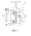
- Figure 1 is a side view of the spinning reel (one example of a fishing reel) 100
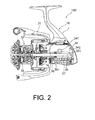
- Figure 2 is a cross-sectional view of the spinning reel 100.
- the spinning reel 100 forwardly unreels a fishing line (in the upper left direction in Figure 1 ).
- the spinning reel 100 comprises a reel body (one example of a second component member) 10, a rotor 31, a spool 32, and a handle 33.
- the spinning reel 100 further comprises a drive mechanism 34, an oscillating mechanism 35, a pinion gear 36, and a spool shaft 37.
- the reel body 10 comprises an internal space and houses various mechanisms in the internal space.
- the drive mechanism 34 and the oscillating mechanism 35 are housed in the reel body 10.
- the drive mechanism 34 comprises a drive shaft 341 and a drive gear 342.
- the drive shaft 341 is coupled with a handle shaft 331 and integrally rotates with the handle shaft 331.
- the spinning reel 100 further comprises a first axle bearing member 38 and a second axle bearing member 39.
- the first and the second axle bearing members 38 and 39 are mounted to the reel body 10 as discussed below, and they rotatably support the drive shaft 341.
- Figure 3 is an A-A line cross-sectional view of Figure 1 that shows only the reel body 10 to which the first and the second axle bearing members 38 and 39 are mounted.
- the second axle bearing member 39 corresponds to the first component member of the present invention.
- the drive gear 342 is coupled to the drive shaft 341 and integrally rotates with the drive shaft 341.
- the drive gear 342 is a face gear and meshes with the gear portion 361 of the pinion gear 36.
- the drive shaft 341 and the drive gear 342 rotate by rotating the handle 33 that is mounted to the side surface of the reel body 10, and the pinion gear 36 also rotates.
- the reel body 10 comprises a case part 1 and a lid portion 2.
- the lid portion 2 can be detached from the case part 1.
- a coated surface is formed on the entire case part 1 and the lid portion 2 by electro-deposition coating.
- the reel body 10 corresponds to the second component member of the present invention; more specifically, the lid portion 2 of the reel body 10 corresponds to the second component member of the present invention.
- Figure 4 is a side view of the case part 1.
- the case part 1 comprises an internal space 11 that opens to the side (the front side of the sheet in Figure 4 ).
- the drive mechanism 34 and the oscillating mechanism 35, etc., mentioned above are stored in the internal space 11 of the case part 1.
- the case part 1 comprises a first fitting recess 12.
- the first axle bearing member 38 fits into the first fitting recess 12 (refer to Figure 3 ).
- the case part 1 comprises a mounting portion 13 that extends in the longitudinal direction.
- the mounting portion 13 is a portion that is mounted to the fishing rod.
- Figure 5 is a perspective view of the lid portion 2
- Figure 6 is a cross-sectional view of the A-A line in Figure 1 .
- Figure 6 shows only the lid portion 2.
- the lid portion 2 is a member for blocking the opening of the case part 1.
- the lid portion 2 comprises a second fitting recess 21, a groove 22, and a side wall 23. Additionally, the second fitting recess 21 corresponds to the fitting recess of the present invention.
- the second fitting recess 21 comprises an inner surface 211 and a bottom surface 212.
- the second fitting recess 21 is fixed by the inner surface 211 and the bottom surface 212.
- the second axle bearing member 39 fits into the second fitting recess 21 (refer to Figure 3 ).
- the inner surface 211 and the bottom surface 212 come into contact with the second axle bearing member 39.
- the inner surface 211 is formed across the entire circumference of the second fitting recess 21. That is, the inner surface 211 forms a circumferential surface.
- a through-hole 213 is formed on the center portion of the bottom surface 212 of the second fitting recess 21. Accordingly, the bottom surface 212 is formed in an annular shape. Further, the handle shaft 331 and the drive shaft 341 extend through the through-hole 213.
- the side wall 23 is formed in a nearly cylindrical shape. This side wall 23 comprises the inner surface 211 mentioned above and the outer surface 231.
- the groove 22 is formed on the inner surface 211.
- the groove 22 is formed in an annular shape. That is, the groove 22 is formed across the entire circumference of the end of the inner surface 211 on the bottom surface 212 side.
- This groove 22 is formed by, for example, a T-slot.
- the depth d of the groove 22 is not particularly limited and may be, for example, greater than or equal to around 0.1 mm and less than or equal to 2 mm.
- the lid portion 2 is configured to be hung on the case part 1.
- the lid portion 2 comprises a hanging portion 24.
- the lid portion 2 comprises two hanging portions 24.
- a through-hole 241 is formed on the hanging portion 24, and the lid portion 2 can be hung using this through-hole 241. Meanwhile, this through-hole 241 of the hanging portion 24 is also used as a hole to pass along a bolt for attaching the lid portion 2 to the case part 1.
- the spool shaft 37 is disposed in the reel body 10.
- the spool shaft 37 extends forward from inside of the reel body 10.
- the spool shaft 37 moves reciprocally in the longitudinal direction by rotation the handle 33.
- the rotation of the handle 33 rotates the pinion gear 36 via the drive gear 342.
- the oscillating mechanism 35 reciprocally moves with the spool shaft 37 in the longitudinal direction.
- the spool 32 is a member to which the fishing line is wound.
- the spool 32 is mounted to the distal end section of the spool shaft 37 via a drag mechanism 40.
- the spool 32 integrally and reciprocally moves with the spool shaft 37 in the longitudinal direction.
- the pinion gear 36 is disposed in the reel body 10.
- the pinion gear 36 extends forward from inside of the reel body 10.
- the pinion gear 36 is rotatably disposed around the spool shaft 37.
- the pinion gear 36 is formed in a tubular shape, and the spool shaft 37 extends inside of the pinion gear 36. Meanwhile, the pinion gear 36 is supported by the reel body 10 via a plurality of axle bearing members.
- the rotor 31 is a member for winding the fishing line onto the spool 32.
- the rotor 31 is fixed to the front portion of the pinion gear 36 and integrally rotates with the pinion gear 36. Therefore, the rotor 31 is non-rotatable relative to the pinion gear 36.
- the spinning reel 100 according to the present embodiment has the following characteristics.
- the spinning reel 100 comprises a reel body 10.
- the lid portion 2 of the reel body 10 comprises a second fitting recess 21 and a groove 22.
- the second axle bearing member 39 fits into the second fitting recess 21.
- the second fitting recess 21 comprises an inner surface 211 that contacts the second axle bearing member 39 and a bottom surface 212 that contacts the second axle bearing member 39.
- the groove 22 is formed on the inner surface 211.
- a groove 22 is formed on the inner surface 211 of the second fitting recess 21.
- the paint will not easily accumulate in the second fitting recess 21. Therefore, the excess paint that accumulates in the second fitting recess 21 can be collected in the groove 22, so that the paint does not easily accumulate in the second fitting recess 21, specifically, on the inner surface 211 that contacts the second axle bearing member 39 and the surface of the bottom surface 212 that contacts the second axle bearing member 39. Therefore, when the second axle bearing member 39 fits into the second fitting recess 21, the second axle bearing member 39 accurately fits into the second fitting recess 21. As a result, a reduction in the rotational accuracy due to a misalignment or the tilting of the axis of the axle bearing member can be prevented; therefore, a reduction in the dimensional accuracy of the spinning reel 100 can be prevented.
- the groove 22 can extend through the side wall 23 from the inner surface 211 toward the outer surface 231.
- the groove 22 is preferably not formed around the entire circumference of the inner surface 211 but is formed on only one portion thereof.
- the groove 22 is preferably formed on the lower portion of the inner surface 211 in a state in which the lid portion 2 is hung.
- the groove 22 is preferably formed on a position that is farthest from the hanging portion 24 on the inner surface 211.
- the groove 22 preferably extends from the end of the side wall 23 on the bottom surface 212 side to the end of the distal end side. That is, the side wall 23 is separated by the groove 22.
- the groove 22 is formed on the inner surface 211, but the configuration is not limited to this embodiment.
- the groove 22 can be formed on the bottom surface 212.
- the groove 22 is preferably formed on the end of the bottom surface 212 on the inner surface 211 side. Additionally, the groove 22 is preferably formed around the entire circumference of the bottom surface 212.
- the lid portion 2 corresponds to the second component member of the present invention, but the configuration is not limited to this embodiment.
- the case part 1 of the reel body 10 can also be configured to correspond to the second component member of the present invention.
- a groove can be formed on the inner surface or on the bottom surface of the first fitting recess 12 of the case part 1 of the reel body 10.
Landscapes
- Life Sciences & Earth Sciences (AREA)
- Environmental Sciences (AREA)
- Animal Husbandry (AREA)
- Biodiversity & Conservation Biology (AREA)
Abstract
Description
- The present invention relates to a fishing reel.
- In general, a fishing reel comprises a fitted member (or component member) that comprises a fitting recess that fits a fitting member (or component member). For example, an axle bearing member, which is a fitting member, fits into the fitting recess of a fitted member. Specifically, a fishing reel comprises a reel body, which is a fitted member. The reel body comprises a fitting recess. This axle bearing member rotatably supports a drive shaft.
- In general, a surface layer is formed on the reel body for various purposes. For example,
JP 2004-81114 A - Generally, when electro-deposition coating a reel body, the reel body is immersed in a coating bath. For this reason, there are cases in which the paint will accumulate in the fitting recess of the reel body when it is taken out of the coating bath, and the accumulated paint will harden while still residing in the corners, etc. of the fitting recess. As a result, when the axle bearing member is being fitted into the fitting recess, the axle bearing member may not accurately fit, and the axis of the axle bearing member may be misaligned or tilted, reducing the rotational. Additionally, this problem is not limited to the reel body and the axle bearing member, as this problem can also occur between the various fitted members and the fitting members, causing a problem in which the dimensional accuracy of the entire fishing reel is reduced.
- The object of the present invention is to prevent a reduction in the dimensional accuracy of the component members of a fishing reel.
- A fishing reel according to one aspect of the present invention comprises a second component member. The second component member comprises a fitting recess and a groove. A first component member of the fishing reel fits into the fitting recess. The fitting recess comprises an inner surface that contacts the first component member and a bottom surface that contacts the first component member. The groove is formed on at least one of the inner surface and the bottom surface.
- According to this configuration, a groove is formed on at least one of the inner surface and the bottom surface of the fitting recess. Thus, for example, when the second component member is immersed in a coating bath and then taken out of the coating bath in order to apply electro-deposition coating to the second component member, paint will not easily accumulate in the fitting recess. That is, the excess paint that has accumulated in the fitting recess can be collected in the groove, so that the paint does not easily accumulate in the fitting recess. Therefore, when the first component member fits into the fitting recess, the first component member will accurately fit in the fitting recess. As a result, a reduction in the dimensional accuracy of the fishing reel can be prevented.
- Preferably, the inner surface is formed across the entire circumference of the fitting recess. According to this configuration, the first component member stably fits into the fitting recess.
- Preferably, the groove is formed across the entire circumference of the end of the inner surface on the bottom surface side. According to this configuration, it is possible to reliably suppress the accumulation of liquid, such as paint, in the fitting recess.
- Preferably, the second component member further comprises a side wall having the inner surface and an outer surface.
- Preferably, the groove extends through the side wall from the inner surface to the outer surface. According to this configuration, liquid, such as paint, in the fitting recess can be discharged outside of the fitting recess via the groove. As a result, the accumulation of liquid such as paint in the fitting recess can be reliably suppressed.
- Preferably, the second component member is configured to be hung. Then, in a state in which the second component member is hung, the groove is formed on the lower portion of the inner surface. According to this configuration, when the second component member is hung, the liquid in the fitting recess can flow into the groove.
- Preferably, the first component member is an axle bearing member. Also, preferably, the second component member is a reel body. When the axle bearing member fits into the fitting recess of the reel body, a higher dimensional accuracy is required. For this reason, when the first component member is an axle bearing member and the second component member is a reel body, the present invention is especially useful.
- Preferably, the second component member further comprises a coating layer or coated surface that is formed by electro-deposition coating.
- According to the present invention, a reduction in the dimensional accuracy of the component members of a fishing reel can be prevented.
- Referring now to the attached drawings which form a part of this original disclosure
- Figure 1
- is a side view of a spinning reel;
- Figure 2
- is a cross-sectional view of a spinning reel;
- Figure 3
- is an A-A line cross-sectional view of the reel body;
- Figure 4
- is a side view of a case part;
- Figure 5
- is a perspective view of the lid portion;
- Figure 6
- is an A-A line cross-sectional view of the lid portion;
- Figure 7
- is a perspective view of the lid portion according to a first modified example; and
- Figure 8
- is an A-A line cross-sectional view of the lid portion according to a second modified example.
- The embodiments of the fishing reel according to the present invention will be explained below, with reference to the drawings.
Figure 1 is a side view of the spinning reel (one example of a fishing reel) 100, andFigure 2 is a cross-sectional view of thespinning reel 100. - As shown in
Figure 1 , thespinning reel 100 forwardly unreels a fishing line (in the upper left direction inFigure 1 ). Thespinning reel 100 comprises a reel body (one example of a second component member) 10, arotor 31, aspool 32, and ahandle 33. Also, as shown inFigure 2 , thespinning reel 100 further comprises adrive mechanism 34, anoscillating mechanism 35, apinion gear 36, and aspool shaft 37. - As shown in
Figure 2 , thereel body 10 comprises an internal space and houses various mechanisms in the internal space. In particular, thedrive mechanism 34 and the oscillatingmechanism 35 are housed in thereel body 10. Thedrive mechanism 34 comprises adrive shaft 341 and adrive gear 342. - The
drive shaft 341 is coupled with ahandle shaft 331 and integrally rotates with thehandle shaft 331. As shown inFigure 3 , the spinningreel 100 further comprises a firstaxle bearing member 38 and a secondaxle bearing member 39. The first and the secondaxle bearing members reel body 10 as discussed below, and they rotatably support thedrive shaft 341. Meanwhile,Figure 3 is an A-A line cross-sectional view ofFigure 1 that shows only thereel body 10 to which the first and the secondaxle bearing members axle bearing member 39 corresponds to the first component member of the present invention. - As shown in
Figure 2 , thedrive gear 342 is coupled to thedrive shaft 341 and integrally rotates with thedrive shaft 341. Thedrive gear 342 is a face gear and meshes with thegear portion 361 of thepinion gear 36. Thedrive shaft 341 and thedrive gear 342 rotate by rotating thehandle 33 that is mounted to the side surface of thereel body 10, and thepinion gear 36 also rotates. - As shown in
Figure 1 , thereel body 10 comprises acase part 1 and alid portion 2. Thelid portion 2 can be detached from thecase part 1. A coated surface is formed on theentire case part 1 and thelid portion 2 by electro-deposition coating. Meanwhile, thereel body 10 corresponds to the second component member of the present invention; more specifically, thelid portion 2 of thereel body 10 corresponds to the second component member of the present invention. -
Figure 4 is a side view of thecase part 1. As shown inFigure 4 , thecase part 1 comprises aninternal space 11 that opens to the side (the front side of the sheet inFigure 4 ). Thedrive mechanism 34 and theoscillating mechanism 35, etc., mentioned above are stored in theinternal space 11 of thecase part 1. Thecase part 1 comprises a firstfitting recess 12. The firstaxle bearing member 38 fits into the first fitting recess 12 (refer toFigure 3 ). Also, thecase part 1 comprises a mountingportion 13 that extends in the longitudinal direction. The mountingportion 13 is a portion that is mounted to the fishing rod. -
Figure 5 is a perspective view of thelid portion 2, andFigure 6 is a cross-sectional view of the A-A line inFigure 1 . Meanwhile,Figure 6 shows only thelid portion 2. Thelid portion 2 is a member for blocking the opening of thecase part 1. As shown inFigure 5 and Figure 6 , thelid portion 2 comprises a secondfitting recess 21, agroove 22, and aside wall 23. Additionally, the secondfitting recess 21 corresponds to the fitting recess of the present invention. - As shown in
Figure 6 , the secondfitting recess 21 comprises aninner surface 211 and abottom surface 212. The secondfitting recess 21 is fixed by theinner surface 211 and thebottom surface 212. The secondaxle bearing member 39 fits into the second fitting recess 21 (refer toFigure 3 ). Theinner surface 211 and thebottom surface 212 come into contact with the secondaxle bearing member 39. - The
inner surface 211 is formed across the entire circumference of the secondfitting recess 21. That is, theinner surface 211 forms a circumferential surface. A through-hole 213 is formed on the center portion of thebottom surface 212 of the secondfitting recess 21. Accordingly, thebottom surface 212 is formed in an annular shape. Further, thehandle shaft 331 and thedrive shaft 341 extend through the through-hole 213. - The
side wall 23 is formed in a nearly cylindrical shape. Thisside wall 23 comprises theinner surface 211 mentioned above and theouter surface 231. - The
groove 22 is formed on theinner surface 211. In particular, thegroove 22 is formed in an annular shape. That is, thegroove 22 is formed across the entire circumference of the end of theinner surface 211 on thebottom surface 212 side. Thisgroove 22 is formed by, for example, a T-slot. Meanwhile, the depth d of thegroove 22 is not particularly limited and may be, for example, greater than or equal to around 0.1 mm and less than or equal to 2 mm. - As shown in
Figure 5 , thelid portion 2 is configured to be hung on thecase part 1. In particular, thelid portion 2 comprises a hangingportion 24. In the present embodiment, thelid portion 2 comprises two hangingportions 24. A through-hole 241 is formed on the hangingportion 24, and thelid portion 2 can be hung using this through-hole 241. Meanwhile, this through-hole 241 of the hangingportion 24 is also used as a hole to pass along a bolt for attaching thelid portion 2 to thecase part 1. - As shown in
Figure 2 , thespool shaft 37 is disposed in thereel body 10. In particular, thespool shaft 37 extends forward from inside of thereel body 10. Thespool shaft 37 moves reciprocally in the longitudinal direction by rotation thehandle 33. In particular, the rotation of thehandle 33 rotates thepinion gear 36 via thedrive gear 342. Accompanying the rotation of thispinion gear 36, theoscillating mechanism 35 reciprocally moves with thespool shaft 37 in the longitudinal direction. - The
spool 32 is a member to which the fishing line is wound. Thespool 32 is mounted to the distal end section of thespool shaft 37 via a drag mechanism 40. Thespool 32 integrally and reciprocally moves with thespool shaft 37 in the longitudinal direction. - The
pinion gear 36 is disposed in thereel body 10. In particular, thepinion gear 36 extends forward from inside of thereel body 10. Thepinion gear 36 is rotatably disposed around thespool shaft 37. Thepinion gear 36 is formed in a tubular shape, and thespool shaft 37 extends inside of thepinion gear 36. Meanwhile, thepinion gear 36 is supported by thereel body 10 via a plurality of axle bearing members. - The
rotor 31 is a member for winding the fishing line onto thespool 32. Therotor 31 is fixed to the front portion of thepinion gear 36 and integrally rotates with thepinion gear 36. Therefore, therotor 31 is non-rotatable relative to thepinion gear 36. - The spinning
reel 100 according to the present embodiment has the following characteristics. - The spinning
reel 100 comprises areel body 10. Thelid portion 2 of thereel body 10 comprises a secondfitting recess 21 and agroove 22. The secondaxle bearing member 39 fits into the secondfitting recess 21. The secondfitting recess 21 comprises aninner surface 211 that contacts the secondaxle bearing member 39 and abottom surface 212 that contacts the secondaxle bearing member 39. Thegroove 22 is formed on theinner surface 211. - According to this configuration, a
groove 22 is formed on theinner surface 211 of the secondfitting recess 21. For this reason, for example, when thelid portion 2 is immersed in a coating bath and then taken out from the coating bath in order to apply electro-deposition coating on thelid portion 2, the paint will not easily accumulate in the secondfitting recess 21. Therefore, the excess paint that accumulates in the secondfitting recess 21 can be collected in thegroove 22, so that the paint does not easily accumulate in the secondfitting recess 21, specifically, on theinner surface 211 that contacts the secondaxle bearing member 39 and the surface of thebottom surface 212 that contacts the secondaxle bearing member 39. Therefore, when the secondaxle bearing member 39 fits into the secondfitting recess 21, the secondaxle bearing member 39 accurately fits into the secondfitting recess 21. As a result, a reduction in the rotational accuracy due to a misalignment or the tilting of the axis of the axle bearing member can be prevented; therefore, a reduction in the dimensional accuracy of the spinningreel 100 can be prevented. - As shown in
Figure 7 , thegroove 22 can extend through theside wall 23 from theinner surface 211 toward theouter surface 231. In this configuration, thegroove 22 is preferably not formed around the entire circumference of theinner surface 211 but is formed on only one portion thereof. Specifically, thegroove 22 is preferably formed on the lower portion of theinner surface 211 in a state in which thelid portion 2 is hung. For example, thegroove 22 is preferably formed on a position that is farthest from the hangingportion 24 on theinner surface 211. Additionally, thegroove 22 preferably extends from the end of theside wall 23 on thebottom surface 212 side to the end of the distal end side. That is, theside wall 23 is separated by thegroove 22. - In the above-described embodiment, the
groove 22 is formed on theinner surface 211, but the configuration is not limited to this embodiment. For example, as shown inFigure 8 , thegroove 22 can be formed on thebottom surface 212. In this configuration, thegroove 22 is preferably formed on the end of thebottom surface 212 on theinner surface 211 side. Additionally, thegroove 22 is preferably formed around the entire circumference of thebottom surface 212. - In the above-described embodiment, the
lid portion 2 corresponds to the second component member of the present invention, but the configuration is not limited to this embodiment. For example, thecase part 1 of thereel body 10 can also be configured to correspond to the second component member of the present invention. Specifically, a groove can be formed on the inner surface or on the bottom surface of the firstfitting recess 12 of thecase part 1 of thereel body 10. - In the above-described embodiment, an example in which the present invention is applied to a spinning reel was explained, but the present invention can also be applied to a dual-bearing reel.
-
- 100
- spinning reel/ fishing reel
- 1
- case part
- 2
- lid portion/ second component member
- 10
- reel body
- 11
- internal space
- 12
- first fitting recess
- 13
- mounting portion
- 21
- second fitting recess
- 211
- inner surface
- 212
- bottom surface
- 213
- through hole
- 22
- groove
- 23
- side wall
- 231
- outer surface
- 24
- hanging portion
- 241
- through hole
- 31
- rotor
- 32
- spool
- 33
- handle
- 331
- handle shaft
- 34
- drive mechanism
- 341
- drive shaft
- 342
- drive gear
- 35
- oscillating mechanism
- 36
- pinion gear
- 361
- gear portion
- 37
- spool shaft
- 38
- first axial bearing member
- 39
- second axle bearing member/ first component member
Claims (9)
- A fishing reel (100), comprising:a first component member (39), anda second component member (2) configured to fit with the first component member (39), and having a fitting recess (21) and a groove (22), the fitting recess (22) having an inner surface (211) to contact the first component member (39), and a bottom surface (212) to contact the first component member (39), and the groove (22) being formed on at least one of the inner surface (211) and the bottom surface (212).
- The fishing reel (100) recited in claim 1, wherein the inner surface (211) is formed across an entire circumference of the fitting recess (21).
- The fishing reel (100) recited in claim 1 or 2, wherein the groove (22) is formed on an end of an entirety of the inner surface (211) adjacent the bottom surface (212).
- The fishing reel (100) recited in claims 1 to 3, wherein the second component member (2) comprises a side wall (23) that includes the inner surface (211) and an outer surface (231).
- The fishing reel (100) recited in claim 4, wherein the groove (22) extends through the side wall (23) from the inner surface (211) toward the outer surface (231).
- The fishing reel (100) recited in claims 1 to 5, wherein the second component member (2) is configured to be hung such that the groove (22) is formed on a lower portion of the inner surface (211).
- The fishing reel (100) recited in claims 1 to 6, wherein the second component member (2) is a reel body.
- The fishing reel (100) recited in claims 1 to 7, wherein the first component member (39) is an axle bearing member.
- The fishing reel (100) recited in claims 1 to 8, wherein the second component member (2) comprises a coating layer which is formed by an electro-deposition coating.
Applications Claiming Priority (1)
| Application Number | Priority Date | Filing Date | Title |
|---|---|---|---|
| JP2014010115A JP6395383B2 (en) | 2014-01-23 | 2014-01-23 | Fishing reel |
Publications (2)
| Publication Number | Publication Date |
|---|---|
| EP2898771A1 true EP2898771A1 (en) | 2015-07-29 |
| EP2898771B1 EP2898771B1 (en) | 2017-02-08 |
Family
ID=52292684
Family Applications (1)
| Application Number | Title | Priority Date | Filing Date |
|---|---|---|---|
| EP14200133.8A Active EP2898771B1 (en) | 2014-01-23 | 2014-12-23 | Fishing reel |
Country Status (7)
| Country | Link |
|---|---|
| US (1) | US9615554B2 (en) |
| EP (1) | EP2898771B1 (en) |
| JP (1) | JP6395383B2 (en) |
| KR (1) | KR102275976B1 (en) |
| CN (1) | CN104798745B (en) |
| MY (1) | MY168493A (en) |
| TW (1) | TWI624222B (en) |
Families Citing this family (1)
| Publication number | Priority date | Publication date | Assignee | Title |
|---|---|---|---|---|
| JP6976814B2 (en) * | 2017-10-30 | 2021-12-08 | 株式会社シマノ | Spinning reel |
Citations (3)
| Publication number | Priority date | Publication date | Assignee | Title |
|---|---|---|---|---|
| JP2001028979A (en) * | 1999-07-21 | 2001-02-06 | Daiwa Seiko Inc | Spinning reel for fishing |
| EP1155612A1 (en) * | 2000-05-17 | 2001-11-21 | Shimano Inc. | Coated fishing components |
| JP2004081114A (en) | 2002-08-27 | 2004-03-18 | Daiwa Seiko Inc | Fishing reel |
Family Cites Families (8)
| Publication number | Priority date | Publication date | Assignee | Title |
|---|---|---|---|---|
| JP3515880B2 (en) * | 1997-06-30 | 2004-04-05 | ダイワ精工株式会社 | Fishing reel |
| JP3955725B2 (en) * | 2000-11-10 | 2007-08-08 | ダイワ精工株式会社 | Double bearing reel for fishing |
| JP2004082612A (en) | 2002-08-28 | 2004-03-18 | Shimano Inc | Outdoor appearance parts |
| US7175121B2 (en) * | 2003-10-28 | 2007-02-13 | Shimano Inc. | Spinning reel sounding mechanism |
| SG144041A1 (en) | 2006-12-21 | 2008-07-29 | Shimano Kk | Reel unit of spinning reel |
| JP4804330B2 (en) * | 2006-12-21 | 2011-11-02 | 株式会社シマノ | Spinning reel body |
| US20080216383A1 (en) * | 2007-03-07 | 2008-09-11 | David Pierick | High performance nano-metal hybrid fishing tackle |
| JP5956741B2 (en) * | 2011-11-08 | 2016-07-27 | 株式会社シマノ | Fishing reel body and fishing reel |
-
2014
- 2014-01-23 JP JP2014010115A patent/JP6395383B2/en active Active
- 2014-09-11 KR KR1020140120029A patent/KR102275976B1/en active Active
- 2014-09-23 TW TW103132851A patent/TWI624222B/en active
- 2014-10-30 US US14/528,080 patent/US9615554B2/en active Active
- 2014-12-03 MY MYPI2014703608A patent/MY168493A/en unknown
- 2014-12-23 EP EP14200133.8A patent/EP2898771B1/en active Active
-
2015
- 2015-01-23 CN CN201510033837.0A patent/CN104798745B/en active Active
Patent Citations (3)
| Publication number | Priority date | Publication date | Assignee | Title |
|---|---|---|---|---|
| JP2001028979A (en) * | 1999-07-21 | 2001-02-06 | Daiwa Seiko Inc | Spinning reel for fishing |
| EP1155612A1 (en) * | 2000-05-17 | 2001-11-21 | Shimano Inc. | Coated fishing components |
| JP2004081114A (en) | 2002-08-27 | 2004-03-18 | Daiwa Seiko Inc | Fishing reel |
Also Published As
| Publication number | Publication date |
|---|---|
| US20150201598A1 (en) | 2015-07-23 |
| CN104798745B (en) | 2019-10-25 |
| EP2898771B1 (en) | 2017-02-08 |
| MY168493A (en) | 2018-11-12 |
| JP6395383B2 (en) | 2018-09-26 |
| KR102275976B1 (en) | 2021-07-12 |
| TW201528943A (en) | 2015-08-01 |
| KR20150088168A (en) | 2015-07-31 |
| TWI624222B (en) | 2018-05-21 |
| JP2015136338A (en) | 2015-07-30 |
| US9615554B2 (en) | 2017-04-11 |
| CN104798745A (en) | 2015-07-29 |
Similar Documents
| Publication | Publication Date | Title |
|---|---|---|
| US9091350B2 (en) | Spinning reel waterproofing member and spinning reel using the same | |
| EP3202261B1 (en) | Spinning reel for fishing | |
| KR101979018B1 (en) | Fishing-reel reel unit and fishing reel | |
| EP3498092B1 (en) | Fishing spinning reel | |
| EP3028566B1 (en) | Line roller unit and fishing line guide mechanism | |
| TWI641317B (en) | Fishing reel, reel for fishing reel and reel shaft for fishing reel | |
| EP2883451B1 (en) | Spinning reel | |
| EP2708120A1 (en) | Spinning reel | |
| EP3195725B1 (en) | Rotor for a spinning reel for fishing | |
| EP2898771B1 (en) | Fishing reel | |
| CN1817122B (en) | Spinning reel handle assembly | |
| EP2995198B1 (en) | Line roller | |
| KR20190016430A (en) | Dual-bearing reel | |
| TWI731021B (en) | Dual-bearing reel | |
| JP6636236B2 (en) | Handle cap | |
| JP2015136338A5 (en) | ||
| JP6335528B2 (en) | Reel body of double-bearing reel | |
| KR102966107B1 (en) | Spinning reel for fishing | |
| KR102232592B1 (en) | Single bearing reel | |
| JP7384851B2 (en) | spinning reel for fishing | |
| JP2021132556A (en) | Spinning reel for fishing | |
| JP2009022167A (en) | Spinning reel rotor |
Legal Events
| Date | Code | Title | Description |
|---|---|---|---|
| PUAI | Public reference made under article 153(3) epc to a published international application that has entered the european phase |
Free format text: ORIGINAL CODE: 0009012 |
|
| 17P | Request for examination filed |
Effective date: 20141223 |
|
| AK | Designated contracting states |
Kind code of ref document: A1 Designated state(s): AL AT BE BG CH CY CZ DE DK EE ES FI FR GB GR HR HU IE IS IT LI LT LU LV MC MK MT NL NO PL PT RO RS SE SI SK SM TR |
|
| AX | Request for extension of the european patent |
Extension state: BA ME |
|
| 17P | Request for examination filed |
Effective date: 20150925 |
|
| RBV | Designated contracting states (corrected) |
Designated state(s): AL AT BE BG CH CY CZ DE DK EE ES FI FR GB GR HR HU IE IS IT LI LT LU LV MC MK MT NL NO PL PT RO RS SE SI SK SM TR |
|
| RAP1 | Party data changed (applicant data changed or rights of an application transferred) |
Owner name: SHIMANO INC. |
|
| GRAP | Despatch of communication of intention to grant a patent |
Free format text: ORIGINAL CODE: EPIDOSNIGR1 |
|
| RIC1 | Information provided on ipc code assigned before grant |
Ipc: A01K 89/015 20060101ALI20160824BHEP Ipc: A01K 89/00 20060101AFI20160824BHEP Ipc: A01K 89/01 20060101ALI20160824BHEP |
|
| INTG | Intention to grant announced |
Effective date: 20160908 |
|
| GRAJ | Information related to disapproval of communication of intention to grant by the applicant or resumption of examination proceedings by the epo deleted |
Free format text: ORIGINAL CODE: EPIDOSDIGR1 |
|
| GRAP | Despatch of communication of intention to grant a patent |
Free format text: ORIGINAL CODE: EPIDOSNIGR1 |
|
| INTC | Intention to grant announced (deleted) | ||
| GRAS | Grant fee paid |
Free format text: ORIGINAL CODE: EPIDOSNIGR3 |
|
| INTG | Intention to grant announced |
Effective date: 20161109 |
|
| GRAA | (expected) grant |
Free format text: ORIGINAL CODE: 0009210 |
|
| AK | Designated contracting states |
Kind code of ref document: B1 Designated state(s): AL AT BE BG CH CY CZ DE DK EE ES FI FR GB GR HR HU IE IS IT LI LT LU LV MC MK MT NL NO PL PT RO RS SE SI SK SM TR |
|
| REG | Reference to a national code |
Ref country code: GB Ref legal event code: FG4D |
|
| REG | Reference to a national code |
Ref country code: CH Ref legal event code: EP Ref country code: AT Ref legal event code: REF Ref document number: 866463 Country of ref document: AT Kind code of ref document: T Effective date: 20170215 |
|
| REG | Reference to a national code |
Ref country code: IE Ref legal event code: FG4D |
|
| REG | Reference to a national code |
Ref country code: DE Ref legal event code: R096 Ref document number: 602014006715 Country of ref document: DE |
|
| REG | Reference to a national code |
Ref country code: LT Ref legal event code: MG4D |
|
| REG | Reference to a national code |
Ref country code: NL Ref legal event code: MP Effective date: 20170208 |
|
| REG | Reference to a national code |
Ref country code: AT Ref legal event code: MK05 Ref document number: 866463 Country of ref document: AT Kind code of ref document: T Effective date: 20170208 |
|
| PG25 | Lapsed in a contracting state [announced via postgrant information from national office to epo] |
Ref country code: LT Free format text: LAPSE BECAUSE OF FAILURE TO SUBMIT A TRANSLATION OF THE DESCRIPTION OR TO PAY THE FEE WITHIN THE PRESCRIBED TIME-LIMIT Effective date: 20170208 Ref country code: HR Free format text: LAPSE BECAUSE OF FAILURE TO SUBMIT A TRANSLATION OF THE DESCRIPTION OR TO PAY THE FEE WITHIN THE PRESCRIBED TIME-LIMIT Effective date: 20170208 Ref country code: GR Free format text: LAPSE BECAUSE OF FAILURE TO SUBMIT A TRANSLATION OF THE DESCRIPTION OR TO PAY THE FEE WITHIN THE PRESCRIBED TIME-LIMIT Effective date: 20170509 Ref country code: FI Free format text: LAPSE BECAUSE OF FAILURE TO SUBMIT A TRANSLATION OF THE DESCRIPTION OR TO PAY THE FEE WITHIN THE PRESCRIBED TIME-LIMIT Effective date: 20170208 Ref country code: NO Free format text: LAPSE BECAUSE OF FAILURE TO SUBMIT A TRANSLATION OF THE DESCRIPTION OR TO PAY THE FEE WITHIN THE PRESCRIBED TIME-LIMIT Effective date: 20170508 |
|
| PG25 | Lapsed in a contracting state [announced via postgrant information from national office to epo] |
Ref country code: LV Free format text: LAPSE BECAUSE OF FAILURE TO SUBMIT A TRANSLATION OF THE DESCRIPTION OR TO PAY THE FEE WITHIN THE PRESCRIBED TIME-LIMIT Effective date: 20170208 Ref country code: AT Free format text: LAPSE BECAUSE OF FAILURE TO SUBMIT A TRANSLATION OF THE DESCRIPTION OR TO PAY THE FEE WITHIN THE PRESCRIBED TIME-LIMIT Effective date: 20170208 Ref country code: ES Free format text: LAPSE BECAUSE OF FAILURE TO SUBMIT A TRANSLATION OF THE DESCRIPTION OR TO PAY THE FEE WITHIN THE PRESCRIBED TIME-LIMIT Effective date: 20170208 Ref country code: BG Free format text: LAPSE BECAUSE OF FAILURE TO SUBMIT A TRANSLATION OF THE DESCRIPTION OR TO PAY THE FEE WITHIN THE PRESCRIBED TIME-LIMIT Effective date: 20170508 Ref country code: NL Free format text: LAPSE BECAUSE OF FAILURE TO SUBMIT A TRANSLATION OF THE DESCRIPTION OR TO PAY THE FEE WITHIN THE PRESCRIBED TIME-LIMIT Effective date: 20170208 Ref country code: SE Free format text: LAPSE BECAUSE OF FAILURE TO SUBMIT A TRANSLATION OF THE DESCRIPTION OR TO PAY THE FEE WITHIN THE PRESCRIBED TIME-LIMIT Effective date: 20170208 Ref country code: RS Free format text: LAPSE BECAUSE OF FAILURE TO SUBMIT A TRANSLATION OF THE DESCRIPTION OR TO PAY THE FEE WITHIN THE PRESCRIBED TIME-LIMIT Effective date: 20170208 Ref country code: PT Free format text: LAPSE BECAUSE OF FAILURE TO SUBMIT A TRANSLATION OF THE DESCRIPTION OR TO PAY THE FEE WITHIN THE PRESCRIBED TIME-LIMIT Effective date: 20170608 |
|
| PG25 | Lapsed in a contracting state [announced via postgrant information from national office to epo] |
Ref country code: IT Free format text: LAPSE BECAUSE OF FAILURE TO SUBMIT A TRANSLATION OF THE DESCRIPTION OR TO PAY THE FEE WITHIN THE PRESCRIBED TIME-LIMIT Effective date: 20170208 Ref country code: EE Free format text: LAPSE BECAUSE OF FAILURE TO SUBMIT A TRANSLATION OF THE DESCRIPTION OR TO PAY THE FEE WITHIN THE PRESCRIBED TIME-LIMIT Effective date: 20170208 Ref country code: CZ Free format text: LAPSE BECAUSE OF FAILURE TO SUBMIT A TRANSLATION OF THE DESCRIPTION OR TO PAY THE FEE WITHIN THE PRESCRIBED TIME-LIMIT Effective date: 20170208 Ref country code: SK Free format text: LAPSE BECAUSE OF FAILURE TO SUBMIT A TRANSLATION OF THE DESCRIPTION OR TO PAY THE FEE WITHIN THE PRESCRIBED TIME-LIMIT Effective date: 20170208 Ref country code: RO Free format text: LAPSE BECAUSE OF FAILURE TO SUBMIT A TRANSLATION OF THE DESCRIPTION OR TO PAY THE FEE WITHIN THE PRESCRIBED TIME-LIMIT Effective date: 20170208 |
|
| REG | Reference to a national code |
Ref country code: DE Ref legal event code: R097 Ref document number: 602014006715 Country of ref document: DE |
|
| PG25 | Lapsed in a contracting state [announced via postgrant information from national office to epo] |
Ref country code: PL Free format text: LAPSE BECAUSE OF FAILURE TO SUBMIT A TRANSLATION OF THE DESCRIPTION OR TO PAY THE FEE WITHIN THE PRESCRIBED TIME-LIMIT Effective date: 20170208 Ref country code: DK Free format text: LAPSE BECAUSE OF FAILURE TO SUBMIT A TRANSLATION OF THE DESCRIPTION OR TO PAY THE FEE WITHIN THE PRESCRIBED TIME-LIMIT Effective date: 20170208 Ref country code: SM Free format text: LAPSE BECAUSE OF FAILURE TO SUBMIT A TRANSLATION OF THE DESCRIPTION OR TO PAY THE FEE WITHIN THE PRESCRIBED TIME-LIMIT Effective date: 20170208 |
|
| PLBE | No opposition filed within time limit |
Free format text: ORIGINAL CODE: 0009261 |
|
| STAA | Information on the status of an ep patent application or granted ep patent |
Free format text: STATUS: NO OPPOSITION FILED WITHIN TIME LIMIT |
|
| REG | Reference to a national code |
Ref country code: FR Ref legal event code: PLFP Year of fee payment: 4 |
|
| 26N | No opposition filed |
Effective date: 20171109 |
|
| PGFP | Annual fee paid to national office [announced via postgrant information from national office to epo] |
Ref country code: LU Payment date: 20171219 Year of fee payment: 4 |
|
| PG25 | Lapsed in a contracting state [announced via postgrant information from national office to epo] |
Ref country code: SI Free format text: LAPSE BECAUSE OF FAILURE TO SUBMIT A TRANSLATION OF THE DESCRIPTION OR TO PAY THE FEE WITHIN THE PRESCRIBED TIME-LIMIT Effective date: 20170208 |
|
| REG | Reference to a national code |
Ref country code: CH Ref legal event code: PL |
|
| REG | Reference to a national code |
Ref country code: IE Ref legal event code: MM4A |
|
| PG25 | Lapsed in a contracting state [announced via postgrant information from national office to epo] |
Ref country code: MT Free format text: LAPSE BECAUSE OF NON-PAYMENT OF DUE FEES Effective date: 20171223 |
|
| REG | Reference to a national code |
Ref country code: BE Ref legal event code: MM Effective date: 20171231 |
|
| PG25 | Lapsed in a contracting state [announced via postgrant information from national office to epo] |
Ref country code: IE Free format text: LAPSE BECAUSE OF NON-PAYMENT OF DUE FEES Effective date: 20171223 |
|
| PG25 | Lapsed in a contracting state [announced via postgrant information from national office to epo] |
Ref country code: CH Free format text: LAPSE BECAUSE OF NON-PAYMENT OF DUE FEES Effective date: 20171231 Ref country code: BE Free format text: LAPSE BECAUSE OF NON-PAYMENT OF DUE FEES Effective date: 20171231 Ref country code: LI Free format text: LAPSE BECAUSE OF NON-PAYMENT OF DUE FEES Effective date: 20171231 |
|
| PG25 | Lapsed in a contracting state [announced via postgrant information from national office to epo] |
Ref country code: HU Free format text: LAPSE BECAUSE OF FAILURE TO SUBMIT A TRANSLATION OF THE DESCRIPTION OR TO PAY THE FEE WITHIN THE PRESCRIBED TIME-LIMIT; INVALID AB INITIO Effective date: 20141223 Ref country code: MC Free format text: LAPSE BECAUSE OF FAILURE TO SUBMIT A TRANSLATION OF THE DESCRIPTION OR TO PAY THE FEE WITHIN THE PRESCRIBED TIME-LIMIT Effective date: 20170208 |
|
| PG25 | Lapsed in a contracting state [announced via postgrant information from national office to epo] |
Ref country code: LU Free format text: LAPSE BECAUSE OF NON-PAYMENT OF DUE FEES Effective date: 20181223 |
|
| PG25 | Lapsed in a contracting state [announced via postgrant information from national office to epo] |
Ref country code: CY Free format text: LAPSE BECAUSE OF FAILURE TO SUBMIT A TRANSLATION OF THE DESCRIPTION OR TO PAY THE FEE WITHIN THE PRESCRIBED TIME-LIMIT Effective date: 20170208 |
|
| PG25 | Lapsed in a contracting state [announced via postgrant information from national office to epo] |
Ref country code: MK Free format text: LAPSE BECAUSE OF FAILURE TO SUBMIT A TRANSLATION OF THE DESCRIPTION OR TO PAY THE FEE WITHIN THE PRESCRIBED TIME-LIMIT Effective date: 20170208 |
|
| PG25 | Lapsed in a contracting state [announced via postgrant information from national office to epo] |
Ref country code: TR Free format text: LAPSE BECAUSE OF FAILURE TO SUBMIT A TRANSLATION OF THE DESCRIPTION OR TO PAY THE FEE WITHIN THE PRESCRIBED TIME-LIMIT Effective date: 20170208 |
|
| PG25 | Lapsed in a contracting state [announced via postgrant information from national office to epo] |
Ref country code: AL Free format text: LAPSE BECAUSE OF FAILURE TO SUBMIT A TRANSLATION OF THE DESCRIPTION OR TO PAY THE FEE WITHIN THE PRESCRIBED TIME-LIMIT Effective date: 20170208 Ref country code: IS Free format text: LAPSE BECAUSE OF FAILURE TO SUBMIT A TRANSLATION OF THE DESCRIPTION OR TO PAY THE FEE WITHIN THE PRESCRIBED TIME-LIMIT Effective date: 20170608 |
|
| PGFP | Annual fee paid to national office [announced via postgrant information from national office to epo] |
Ref country code: GB Payment date: 20201216 Year of fee payment: 7 |
|
| GBPC | Gb: european patent ceased through non-payment of renewal fee |
Effective date: 20211223 |
|
| PG25 | Lapsed in a contracting state [announced via postgrant information from national office to epo] |
Ref country code: GB Free format text: LAPSE BECAUSE OF NON-PAYMENT OF DUE FEES Effective date: 20211223 |
|
| P01 | Opt-out of the competence of the unified patent court (upc) registered |
Effective date: 20230502 |
|
| PGFP | Annual fee paid to national office [announced via postgrant information from national office to epo] |
Ref country code: FR Payment date: 20231108 Year of fee payment: 10 |
|
| PG25 | Lapsed in a contracting state [announced via postgrant information from national office to epo] |
Ref country code: FR Free format text: LAPSE BECAUSE OF NON-PAYMENT OF DUE FEES Effective date: 20241231 |
|
| PGFP | Annual fee paid to national office [announced via postgrant information from national office to epo] |
Ref country code: DE Payment date: 20251028 Year of fee payment: 12 |