EP2898762B1 - Variable speed control systems and methods for walk-behind working machines - Google Patents
Variable speed control systems and methods for walk-behind working machines Download PDFInfo
- Publication number
- EP2898762B1 EP2898762B1 EP15152334.7A EP15152334A EP2898762B1 EP 2898762 B1 EP2898762 B1 EP 2898762B1 EP 15152334 A EP15152334 A EP 15152334A EP 2898762 B1 EP2898762 B1 EP 2898762B1
- Authority
- EP
- European Patent Office
- Prior art keywords
- control lever
- control
- angular position
- handle
- lever
- Prior art date
- Legal status (The legal status is an assumption and is not a legal conclusion. Google has not performed a legal analysis and makes no representation as to the accuracy of the status listed.)
- Active
Links
Images



Classifications
-
- F—MECHANICAL ENGINEERING; LIGHTING; HEATING; WEAPONS; BLASTING
- F16—ENGINEERING ELEMENTS AND UNITS; GENERAL MEASURES FOR PRODUCING AND MAINTAINING EFFECTIVE FUNCTIONING OF MACHINES OR INSTALLATIONS; THERMAL INSULATION IN GENERAL
- F16H—GEARING
- F16H59/00—Control inputs to control units of change-speed- or reversing-gearings for conveying rotary motion
- F16H59/02—Selector apparatus
- F16H59/0278—Constructional features of the selector lever, e.g. grip parts, mounting or manufacturing
-
- A—HUMAN NECESSITIES
- A01—AGRICULTURE; FORESTRY; ANIMAL HUSBANDRY; HUNTING; TRAPPING; FISHING
- A01D—HARVESTING; MOWING
- A01D34/00—Mowers; Mowing apparatus of harvesters
- A01D34/01—Mowers; Mowing apparatus of harvesters characterised by features relating to the type of cutting apparatus
- A01D34/412—Mowers; Mowing apparatus of harvesters characterised by features relating to the type of cutting apparatus having rotating cutters
- A01D34/42—Mowers; Mowing apparatus of harvesters characterised by features relating to the type of cutting apparatus having rotating cutters having cutters rotating about a horizontal axis, e.g. cutting-cylinders
- A01D34/46—Mowers; Mowing apparatus of harvesters characterised by features relating to the type of cutting apparatus having rotating cutters having cutters rotating about a horizontal axis, e.g. cutting-cylinders hand-guided by a walking operator
- A01D34/47—Mowers; Mowing apparatus of harvesters characterised by features relating to the type of cutting apparatus having rotating cutters having cutters rotating about a horizontal axis, e.g. cutting-cylinders hand-guided by a walking operator with motor driven cutters or wheels
- A01D34/475—Driving mechanisms
-
- A—HUMAN NECESSITIES
- A01—AGRICULTURE; FORESTRY; ANIMAL HUSBANDRY; HUNTING; TRAPPING; FISHING
- A01D—HARVESTING; MOWING
- A01D34/00—Mowers; Mowing apparatus of harvesters
- A01D34/01—Mowers; Mowing apparatus of harvesters characterised by features relating to the type of cutting apparatus
- A01D34/412—Mowers; Mowing apparatus of harvesters characterised by features relating to the type of cutting apparatus having rotating cutters
- A01D34/63—Mowers; Mowing apparatus of harvesters characterised by features relating to the type of cutting apparatus having rotating cutters having cutters rotating about a vertical axis
- A01D34/67—Mowers; Mowing apparatus of harvesters characterised by features relating to the type of cutting apparatus having rotating cutters having cutters rotating about a vertical axis hand-guided by a walking operator
- A01D34/68—Mowers; Mowing apparatus of harvesters characterised by features relating to the type of cutting apparatus having rotating cutters having cutters rotating about a vertical axis hand-guided by a walking operator with motor driven cutters or wheels
- A01D34/6806—Driving mechanisms
-
- Y—GENERAL TAGGING OF NEW TECHNOLOGICAL DEVELOPMENTS; GENERAL TAGGING OF CROSS-SECTIONAL TECHNOLOGIES SPANNING OVER SEVERAL SECTIONS OF THE IPC; TECHNICAL SUBJECTS COVERED BY FORMER USPC CROSS-REFERENCE ART COLLECTIONS [XRACs] AND DIGESTS
- Y10—TECHNICAL SUBJECTS COVERED BY FORMER USPC
- Y10T—TECHNICAL SUBJECTS COVERED BY FORMER US CLASSIFICATION
- Y10T74/00—Machine element or mechanism
- Y10T74/20—Control lever and linkage systems
- Y10T74/20012—Multiple controlled elements
- Y10T74/20018—Transmission control
- Y10T74/2014—Manually operated selector [e.g., remotely controlled device, lever, push button, rotary dial, etc.]
Definitions
- the subject matter disclosed herein relates generally to variable control systems for powered equipment. More particularly, the subject matter disclosed herein relates to variable speed controls and methods for walk-behind working machines, such as lawnmowers.
- a control system is typically carried on the handle to allow the operator to engage and disengage the self-propel system and to select a desired ground speed.
- many such control systems use a pivotable ground speed control bail on the handle of the working machine. In such systems, the bail can be pivoted to engage the self-propel system, with the degree of movement of the ground speed control bail dictating the ground speed of the working machine.
- variable speed control systems and methods for walk-behind working machines such as lawnmowers and similar powered machines are provided.
- a variable speed control system for a walk-behind working machine is provided.
- the system can comprise a control system base, a handle, a control lever comprising a lever arm having a first end that is pivotably attached to the control system base and a second end substantially opposing the first end that comprises a grip portion, and a control connector in communication between the control lever and a machine component.
- the control lever can be selectively pivotable with respect to the control system base between a first angular position at which the grip portion of the control lever is spaced apart from the handle by a first angle and a second angular position at which the control lever is proximate to the handle.
- a control lever adjustment system can be configured to selectively adjust the first angle by which the control lever is spaced apart from the handle when the control lever is in the first angular position to adjust the total angular travel of the control lever between the first angular position and the second angular position. Based on this positioning, the control connector can be configured to control the machine component to be in one of a range of operating states corresponding to the angular position of the control lever with respect to the control system base.
- control lever adjustment system comprises a control knob that is rotatable with respect to the control lever, wherein rotation of the control knob causes adjustment of the first angle by which the control lever is spaced apart from the handle when the control lever is in the first angular position.
- control lever adjustment system comprises a bracket positioned in a substantially fixed orientation with respect to the control system base, the bracket comprising a slot configured to constrain the movement of the pin to be in a substantially linear path.
- selectively adjusting the first angle by which the control lever is spaced apart from the handle when the control lever is in the first angular position comprises selectively moving the control lever with respect to a guide assembly connected to the control connector and pivoting the control lever with respect to the control system base comprises moving the control lever relative to the control system base to cause movement of the guide assembly to actuate the control connector.
- moving the pin within the groove in the guide assembly comprises constraining the movement of the pin to be in a substantially linear path.
- selectively moving the control lever with respect to the guide assembly comprises actuating a worm gear connected to the control lever and engaged with the guide assembly to adjust the first angle by which the control lever is spaced apart from the handle when the control lever is in the first angular position.
- pivoting the control lever to the first angular position comprises controlling the machine component to be in a disengaged state and pivoting the control lever to the second angular position comprises controlling the machine component to be in an engaged state, a magnitude of an output of the machine component when in the engaged state being dependent on the total angular travel of the control lever between the first angular position and the second angular position.
- the machine component comprises a variable transmission for a self-propel system of the working machine, and the engaged state comprises operation of the self-propel system at a predetermined cruising speed.
- pivoting the control lever to the second angular position comprises pivoting the control lever to a position at which an outer surface of the grip portion of the control lever is substantially aligned with an outer surface of the handle when the control lever is in the second position.
- selectively adjusting the first angle by which the control lever is spaced apart from the handle when the control lever is in the first angular position comprises rotating a control knob with respect to the control lever.
- the present subject matter provides variable speed control systems and methods for walk-behind working machines, such as lawnmowers and similar powered machines.
- the present subject matter provides variable speed control systems and methods that can vary speed and comfortably hold a desired predetermined fixed speed.
- a variable speed control system generally designated 100 can comprise a handle 110 configured to be gripped by an operator to control the operation of a working machine, such as a lawnmower or other small powered machine, to which handle 110 is connected.
- a control system base 120 can be attached to or otherwise positioned near handle 110, and a control lever 130 can be movably attached to control system base 120.
- control lever generally designated 130 can be moved to control operation of a machine component, such as for example a variable transmission for a self-propel system of the working machine.
- control lever 130 can comprise a lever arm 132 having a first end that is pivotably attached to control system base 120 and a second end substantially opposing the first end that comprises a grip portion 134.
- control lever 130 can have a substantially L-shaped profile, with grip portion 134 extending at a non-zero angle (e.g., between about 50 and 90 degrees) away from lever arm 132. This angular arrangement allows the operator to grab grip portion 134 in a comfortable hand position and pivot control lever 130 with respect to control system base 120.
- control lever 130 can be selectively pivoted with respect to control system base 120 between a first angular position (See, e.g., Figures 1A and 1B ) at which grip portion 134 of control lever 130 is spaced apart from handle 110 and a second angular position (See, e.g., Figures 2A and 2B ) at which grip portion 134 is comparatively closer to handle 110.
- This pivoting movement of control lever 130 can be configured to correspondingly cause changes in the operating state of the connected machine component.
- the machine component can be configured to be in a low-speed or idle state when control lever 130 is in the first angular position and in a high-speed or cruising state when control lever 130 is moved to the second angular position.
- the first operating state can be a disengaged state (i.e., no torque applied)
- the second operating state can be a selected high-speed state (i.e., torque applied to the drive system, such that the working machine is moved at a predetermined cruising speed).
- grip portion 134 can be designed to be positioned within a recess 112 that is formed in an edge of handle 110 when control lever 130 is in the second angular position.
- recess 112 can be designed to be large enough such that grip portion 134 can be nested substantially entirely within recess 112.
- pivoting control lever 130 to the second angular position can involve pivoting control lever 130 into a position in which an outer surface 135 of grip portion 134 of control lever 130 is substantially aligned with an outer surface generally designated 115 of handle 110 (e.g., surfaces substantially flush/even with one another).
- control lever 130 can additionally be pivoted to any of a variety of intermediate angular positions to correspondingly operate the machine component in one or more partial engagement states (e.g., low- to medium-speed operating states of the self-propel system). In this way, the operator can selectively operate the machine component at states between the first and second operating states.
- partial engagement states e.g., low- to medium-speed operating states of the self-propel system.
- this control arrangement can be configured such that the greater the distance that control connector 122 is displaced, the greater the force that is transmitted to the machine component. Accordingly, the magnitude of the output of the machine component corresponding to each operating state (e.g., the speed of the self-propel system) can be controlled by correspondingly controlling the magnitude of the displacement of control connector 122, which can in turn be controlled by correspondingly controlling the angular travel of control lever 130. As a result, greater outputs can be achieved by greater total angular movement of control lever 130.
- this setting establishes the total available angular travel through which control lever 130 can be pivoted
- setting this base position effectively controls the range of operating states of the machine component.
- increasing the total angular travel through which control lever 130 can be pivoted effectively increases the cruising speed when control lever 130 is pivoted to the second angular position proximate to handle 110 (and the over-stroke speed when control lever 130 is depressed into handle 110 to the third angular position).
- Figures 5A and 5B illustrate adjustment of control knob 150 from a minimum base state a to an increased base state b, which moves control lever 130 to a corresponding base angular position with respect to handle 110 (e.g., about 18°).
- Figures 6A and 6B illustrate adjustment of control knob 150 from minimum base state a to a high base state c, which moves control lever 130 to a correspondingly higher base angular position with respect to handle 110 (e.g., about 36°).
- control knob 150 can be turned to any of a variety of intermediate positions corresponding to a variety of angular positions of control lever 130.
Landscapes
- Life Sciences & Earth Sciences (AREA)
- Environmental Sciences (AREA)
- Engineering & Computer Science (AREA)
- General Engineering & Computer Science (AREA)
- Mechanical Engineering (AREA)
- Harvester Elements (AREA)
- Mechanical Control Devices (AREA)
Description
- The subject matter disclosed herein relates generally to variable control systems for powered equipment. More particularly, the subject matter disclosed herein relates to variable speed controls and methods for walk-behind working machines, such as lawnmowers.
- Many walk-behind working machines, such as lawnmowers and other similar small powered equipment, have a self-propel system that propels or drives the working machine at a selected ground speed. In such systems, as for example in document
EP-1.106.046 or in documentUS-2003/046448 , a control system is typically carried on the handle to allow the operator to engage and disengage the self-propel system and to select a desired ground speed. For example, many such control systems use a pivotable ground speed control bail on the handle of the working machine. In such systems, the bail can be pivoted to engage the self-propel system, with the degree of movement of the ground speed control bail dictating the ground speed of the working machine. - In these conventional self-propel systems, however, it can be difficult to maintain the control system in a fixed position corresponding to a desired cruising speed. For example, many control systems lack a fixed position in which the operator can comfortably hold the control bail while operating the working machine at a self-propelled "cruising" speed. In view of these issues, it would be desirable for a ground speed control system to allow for comfortable operation of the working machine at a desired cruising speed.
- In accordance with this disclosure, variable speed control systems and methods for walk-behind working machines, such as lawnmowers and similar powered machines are provided. In one aspect, a variable speed control system for a walk-behind working machine is provided. The system can comprise a control system base, a handle, a control lever comprising a lever arm having a first end that is pivotably attached to the control system base and a second end substantially opposing the first end that comprises a grip portion, and a control connector in communication between the control lever and a machine component. The control lever can be selectively pivotable with respect to the control system base between a first angular position at which the grip portion of the control lever is spaced apart from the handle by a first angle and a second angular position at which the control lever is proximate to the handle. In addition, a control lever adjustment system can be configured to selectively adjust the first angle by which the control lever is spaced apart from the handle when the control lever is in the first angular position to adjust the total angular travel of the control lever between the first angular position and the second angular position. Based on this positioning, the control connector can be configured to control the machine component to be in one of a range of operating states corresponding to the angular position of the control lever with respect to the control system base.
- Preferably, the range of operating states corresponding to the angular position of the control lever comprises a disengaged state of the machine component when the control lever is in the first angular position and an engaged state of the machine component when the control lever is in the second angular position, a magnitude of an output of the machine component when in the engaged state being dependent on the total angular travel of the control lever between the first angular position and the second angular position.
- Preferably, the machine component comprises a variable transmission for a self-propel system of the working machine and the engaged state comprises operation of the self-propel system at a cruising speed determined by the total angular travel of the control lever between the first angular position and the second angular position.
- Preferably, an outer surface of the grip portion of the control lever is substantially aligned with an outer surface of the handle when the control lever is in the second angular position.
- Preferably, the control lever adjustment system comprises a control knob that is rotatable with respect to the control lever, wherein rotation of the control knob causes adjustment of the first angle by which the control lever is spaced apart from the handle when the control lever is in the first angular position.
- Preferably, the control knob is coupled to the control lever.
- Preferably, the control lever adjustment system comprises a guide assembly connected to the control connector;
- wherein the control lever is selectively movable with respect to the guide assembly to adjust the first angle by which the control lever is spaced apart from the handle when the control lever is in the first angular position and movement of the control lever relative to the control system base causes movement of the guide assembly to actuate the control connector.
- the guide assembly comprises a groove, wherein the control connector comprises a pin movable within the groove and movement of the guide assembly causes movement of the pin, which actuates the control connector to cause the machine component to change among the range of operating states.
- Preferably, the control lever adjustment system comprises a bracket positioned in a substantially fixed orientation with respect to the control system base, the bracket comprising a slot configured to constrain the movement of the pin to be in a substantially linear path.
- Preferably, the guide assembly comprises a worm gear connected to the control lever and engaged with the guide assembly, selectively moving the control lever with respect to the guide assembly comprises actuating the worm gear to adjust the first angle by which the control lever is spaced apart from the handle when the control lever is in the first angular position.
- In another aspect, a method for varying a speed of a walk-behind working machine is provided. The method can include, for a control lever that is selectively pivotable about a control system base between a first angular position at which a grip portion of the control lever is spaced apart from a handle by a first angle and a second angular position at which the control lever is proximate to the handle, selectively adjusting the first angle by which the control lever is spaced apart from the handle when the control lever is in the first angular position to adjust the total angular travel of the control lever between the first angular position and the second angular position. The control lever can be pivoted with respect to the control system base between the first angular position and the second angular position. In this way, pivoting the control lever between the first angular position and the second angular position controls a machine component to be in one of a range of operating states corresponding to the angular position of the control lever with respect to the control system base.
- Preferably, pivoting the control lever to control the machine component comprises actuating a control connector in communication between the control lever and the machine component.
- Preferably, selectively adjusting the first angle by which the control lever is spaced apart from the handle when the control lever is in the first angular position comprises selectively moving the control lever with respect to a guide assembly connected to the control connector and pivoting the control lever with respect to the control system base comprises moving the control lever relative to the control system base to cause movement of the guide assembly to actuate the control connector.
- Preferably, moving the control lever relative to the control system base to cause movement of the guide assembly to actuate the control connector comprises moving a pin within a groove in the guide assembly, wherein movement of the pin causes the machine component to change among the range of operating states.
- Preferably, moving the pin within the groove in the guide assembly comprises constraining the movement of the pin to be in a substantially linear path.
- Preferably, selectively moving the control lever with respect to the guide assembly comprises actuating a worm gear connected to the control lever and engaged with the guide assembly to adjust the first angle by which the control lever is spaced apart from the handle when the control lever is in the first angular position.
- Preferably, pivoting the control lever to the first angular position comprises controlling the machine component to be in a disengaged state and pivoting the control lever to the second angular position comprises controlling the machine component to be in an engaged state, a magnitude of an output of the machine component when in the engaged state being dependent on the total angular travel of the control lever between the first angular position and the second angular position.
- Preferably, the machine component comprises a variable transmission for a self-propel system of the working machine, and the engaged state comprises operation of the self-propel system at a predetermined cruising speed.
- Preferably, pivoting the control lever to the second angular position comprises pivoting the control lever to a position at which an outer surface of the grip portion of the control lever is substantially aligned with an outer surface of the handle when the control lever is in the second position.
- Preferably, selectively adjusting the first angle by which the control lever is spaced apart from the handle when the control lever is in the first angular position comprises rotating a control knob with respect to the control lever.
- Although some of the aspects of the subject matter disclosed herein have been stated hereinabove, and which are achieved in whole or in part by the presently disclosed subject matter, other aspects will become evident as the description proceeds when taken in connection with the accompanying drawings as described hereinbelow.
- The features and advantages of the present subject matter will be more readily understood from the following detailed description which should be read in conjunction with the accompanying drawings that are given merely by way of explanatory and non-limiting example, and in which:
-
Figure 1A is a perspective view of a variable speed control system in a first operating position according to an embodiment of the presently disclosed subject matter; -
Figure 1B is a sectional side view of a portion of a handle of the variable speed control system shown inFigure 1A ; -
Figure 2A is a perspective view of a variable speed control system in a second operating position according to an embodiment of the presently disclosed subject matter; -
Figure 2B is a sectional side view of a portion of a handle of the variable speed control system shown inFigure 2A ; -
Figure 3A is a perspective view of a variable speed control system in a third operating position according to an embodiment of the presently disclosed subject matter; -
Figure 3B is a sectional side view of a portion of a handle of the variable speed control system shown inFigure 3A ; -
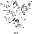
Figure 4A is an exploded perspective view of a variable speed control system according to an embodiment of the presently disclosed subject matter; -
Figure 4B is a side cutaway view of a variable speed control system according to an embodiment of the presently disclosed subject matter; -
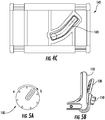
Figure 4C is a side view of a rotatable guide assembly of a variable speed control system according to an embodiment of the presently disclosed subject matter; -
Figure 5A is a top view of a control knob of a variable speed control system in an intermediate operating state according to an embodiment of the presently disclosed subject matter; -
Figure 5B is a side view of a variable speed control system when the control knob is in an intermediate state according to an embodiment of the presently disclosed subject matter; -
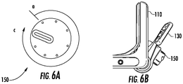
Figure 6A is a top view of a control knob of a variable speed control system in a high operating state according to an embodiment of the presently disclosed subject matter; and -
Figure 6B is a side view of a variable speed control system when the control knob is in a high state according to an embodiment of the presently disclosed subject matter. - The present subject matter provides variable speed control systems and methods for walk-behind working machines, such as lawnmowers and similar powered machines. In one aspect, the present subject matter provides variable speed control systems and methods that can vary speed and comfortably hold a desired predetermined fixed speed.
- Specifically, for instance, as shown in
Figures 1A through 3B , a variable speed control system, generally designated 100 can comprise ahandle 110 configured to be gripped by an operator to control the operation of a working machine, such as a lawnmower or other small powered machine, to whichhandle 110 is connected. Acontrol system base 120 can be attached to or otherwise positioned nearhandle 110, and acontrol lever 130 can be movably attached tocontrol system base 120. With this general configuration, control lever generally designated 130 can be moved to control operation of a machine component, such as for example a variable transmission for a self-propel system of the working machine. - In particular,
control lever 130 can comprise alever arm 132 having a first end that is pivotably attached tocontrol system base 120 and a second end substantially opposing the first end that comprises agrip portion 134. Specifically, for example, as shown inFigures 1A ,2A , and3A ,control lever 130 can have a substantially L-shaped profile, withgrip portion 134 extending at a non-zero angle (e.g., between about 50 and 90 degrees) away fromlever arm 132. This angular arrangement allows the operator to grabgrip portion 134 in a comfortable hand position and pivotcontrol lever 130 with respect to controlsystem base 120. - In this regard, to control the operation of the associated machine component (e.g., a self-propel system),
control lever 130 can be selectively pivoted with respect to controlsystem base 120 between a first angular position (See, e.g.,Figures 1A and 1B ) at whichgrip portion 134 ofcontrol lever 130 is spaced apart fromhandle 110 and a second angular position (See, e.g.,Figures 2A and 2B ) at whichgrip portion 134 is comparatively closer to handle 110. This pivoting movement ofcontrol lever 130 can be configured to correspondingly cause changes in the operating state of the connected machine component. In particular, for example, the machine component can be configured to be in a low-speed or idle state whencontrol lever 130 is in the first angular position and in a high-speed or cruising state whencontrol lever 130 is moved to the second angular position. For instance, where the machine component is a self-propel system for a working machine, the first operating state can be a disengaged state (i.e., no torque applied), and the second operating state can be a selected high-speed state (i.e., torque applied to the drive system, such that the working machine is moved at a predetermined cruising speed). - To help the operator maintain
control lever 130 in the second angular position, at least a portion ofgrip portion 134 can be designed to be positioned within arecess 112 that is formed in an edge ofhandle 110 whencontrol lever 130 is in the second angular position. In the particular configuration shown inFigures 1A through 3B , for example,recess 112 can be designed to be large enough such thatgrip portion 134 can be nested substantially entirely withinrecess 112. In this way, pivotingcontrol lever 130 to the second angular position can involve pivotingcontrol lever 130 into a position in which anouter surface 135 ofgrip portion 134 ofcontrol lever 130 is substantially aligned with an outer surface generally designated 115 of handle 110 (e.g., surfaces substantially flush/even with one another). In this way, the combination ofhandle 110 andgrip portion 134 can fit together such that the operator can comfortably holdcontrol lever 130 in a substantially fixed manner at the second angular position by squeezinggrip portion 134 intorecess 112. With respect to the operation of a self-propel system, for example, this ability to comfortably maintaincontrol lever 130 in the second angular position means that the operator can maintain the working machine at a cruising speed by simply gripping around the nested combination ofhandle 110 andgrip portion 134. - In addition, as shown in
Figures 3A and 3B ,recess 112 can be configured such that it is large enough thatgrip portion 134 can be depressed beyond the point at whichouter surface 135 ofgrip portion 134 is substantially aligned withouter surface 115 ofhandle 110. In this regard,control lever 130 can be further selectively pivotable to a third angular position (See, e.g.,Figures 3A and 3B ) at whichouter surface 135 ofgrip portion 134 ofcontrol lever 130 is depressed intorecess 112 ofhandle 110. Withcontrol lever 130 in this third angular position, variablespeed control system 100 can be configured to control the machine component to be in a third operating state. For instance, the third operating state can comprise an over-stroke state of the machine component that provides additional torque to the self-propel system to account for changing ground conditions (e.g., inclines, uneven ground surfaces). In this way, from the second angular position, if the operator desires to apply additional driving torque (e.g., to travel up a hill),grip portion 134 can be depressed into recess 112 (e.g., by using his/her thumbs to pressgrip portion 134 further into handle 110) to the third angular position. Depending on the configuration ofrecess 112, this additional over-stroke travel from the second angular position to the third angular position can be small compared to the angle of travel between the first angular position and the second angular position. To limit the extent of this over stroke, handle 110 can be configured to define or include astop 116 at the back ofrecess 112 such that once aleading edge 136 ofgrip portion 134 encounters stop 116,control lever 130 is prevented from pivoting any farther. - Furthermore, those having skill in the art will recognize that
control lever 130 can additionally be pivoted to any of a variety of intermediate angular positions to correspondingly operate the machine component in one or more partial engagement states (e.g., low- to medium-speed operating states of the self-propel system). In this way, the operator can selectively operate the machine component at states between the first and second operating states. - This movement of
control lever 130 among the various angular positions discussed above can be used to control the operation of the associated machine component by connecting acontrol connector 122 betweencontrol lever 130 and the machine component. Specifically, for example,control connector 122 can be a Bowden-type cable in which an inner wire is movable with respect to a hollow outer cable housing to transmit a force to the machine component. In this arrangement, pivoting movement ofcontrol lever 130 can cause translation of the inner wire ofcontrol connector 122. In addition, at least a portion ofcontrol connector 122 can be contained within (e.g., routed through)control system base 120 and/or handle 110 to prevent inadvertent actuation ofcontrol connector 122. In this way, the pivoting movement ofcontrol lever 130 can be translated into changes in the operating state of the connected machine component. Those having skill in the art will recognize that any of a variety of other configurations forcontrol connector 122 can be used to translate movement ofcontrol lever 130 into changes in the operation of the connected machine component. For example,control connector 122 can be a wired or wireless electrical signal transmitter that enables communication betweencontrol lever 130 and the machine component. - Regardless of the particular mechanism by which rotation of
control lever 130 is translated into changes in the operating state of the connected machine component, this control arrangement can be configured such that the greater the distance that controlconnector 122 is displaced, the greater the force that is transmitted to the machine component. Accordingly, the magnitude of the output of the machine component corresponding to each operating state (e.g., the speed of the self-propel system) can be controlled by correspondingly controlling the magnitude of the displacement ofcontrol connector 122, which can in turn be controlled by correspondingly controlling the angular travel ofcontrol lever 130. As a result, greater outputs can be achieved by greater total angular movement ofcontrol lever 130. - With this relationship in mind, variable
speed control system 100 can be configured to enable the operator to selectively control the magnitude of the output of the machine component that corresponds to each operating state by modifying the length of the total angular travel ofcontrol lever 130. Because the second angular position ofcontrol lever 130 is defined above by the proximity ofcontrol lever 130 to handle 110 (e.g., SeeFigures 2A and 2B ), such modification of the length of total angular travel ofcontrol lever 130 can be most easily achieved by changing the location of the first angular position ofcontrol lever 130 relative to handle 110 (i.e., a base starting position). - In this regard, variable
speed control system 100 can be configured such that the first angular position ofcontrol lever 130 is selectively adjustable. Specifically, as shown inFigures 4A through 4C , variablespeed control system 100 can comprise a control lever adjustment system, generally designated 140, that is configured to adjust the first angular position ofcontrol lever 130. Controllever adjustment system 140 can include aguide assembly 142 that is rotatable with respect to controlsystem base 120 and that is connected to controlconnector 122 to effect changes in the operating state of the connected machine component. In particular,guide assembly 142 can comprise agroove 143 that is configured to receive acontrol pin 146 therein,control pin 146 being connected to controlconnector 122. In particular, for example, as shown inFigure 4A , guideassembly 142 can comprise afirst guide portion 142a defining afirst groove 143a and asecond guide portion 142b defining asecond groove 143b that are configured to be connected together to form a substantially cylindrical sleeve that surrounds and engagescontrol pin 146. - To constrain the movement of
control pin 146 to be in a predictable and defined path, abracket 144 can be positioned in a substantially fixed orientation with respect to controlsystem base 120 and configured to guidecontrol pin 146 to move in a substantially linear path along a slot 145 formed in bracket 144 (e.g., in a substantially axial direction with respect tobracket 144 and control system base 120). In particular, for example, as shown inFigure 4A ,bracket 144 can comprise afirst bracket portion 144a having afirst slot 145a formed therein and asecond bracket portion 144b having asecond slot 145b formed therein,first bracket portion 144a andsecond bracket portion 144b being configured to be connected together to form a substantially cylindrical shell withinguide assembly 142. Thus, as shown inFigure 4B ,control pin 146 can be constrained bybracket 144, which can be nested withinguide assembly 142. - In this arrangement, rotation of
guide assembly 142 can cause a linear displacement ofcontrol pin 146 to thereby cause actuation ofcontrol connector 122. Specifically, as shown inFigure 4C , whereas slot 145 inbracket 144 can be configured to be substantially linear to guide the movement ofcontrol pin 146,groove 143 inguide assembly 142 can have an arcuate shape. In this way, rotation ofguide assembly 142 exerts a force oncontrol pin 146 that would tend to rotatecontrol pin 146 about a central longitudinal axis ofguide assembly 142. Becausecontrol pin 146 is restrained by slot 145 to only be movable in an axial direction with respect to guideassembly 142, however, the force exerted oncontrol pin 146 causescontrol pin 146 to slide axially alonggroove 143. Accordingly, actuation ofcontrol connector 122 can be controlled by controlling the rotation ofguide assembly 142. - In addition,
guide assembly 142 can be coupled to controllever 130 such that pivoting movement ofcontrol lever 130 causes rotation ofguide assembly 142. In particular, as shown inFigure 4B ,guide assembly 142 can be coupled to controllever 130 by acontrol knob 150 connected to aworm gear 152 that is carried bycontrol lever 130. In this arrangement, rotation ofcontrol knob 150 can cause rotation ofworm gear 152 with respect to controllever 130. This rotation ofworm gear 152 can exert a force on complementary gear teeth provided onguide assembly 142, which can causecontrol lever 130 to pivot with respect to guideassembly 142 andcontrol system base 120. In this way, adjustments in the position ofcontrol knob 150 can result in modifications to the base position (i.e., the first angular position) ofcontrol lever 130 with respect to controlsystem base 120. As a result, the operator can selectively movecontrol knob 150 to set the first angular position ofcontrol lever 130 with respect to controlsystem base 120. - As discussed above, because this setting establishes the total available angular travel through which
control lever 130 can be pivoted, setting this base position effectively controls the range of operating states of the machine component. In other words, where the machine component is a self-propel system, for example, increasing the total angular travel through whichcontrol lever 130 can be pivoted effectively increases the cruising speed whencontrol lever 130 is pivoted to the second angular position proximate to handle 110 (and the over-stroke speed whencontrol lever 130 is depressed intohandle 110 to the third angular position). - Specifically, for example,
Figures 5A and 5B illustrate adjustment ofcontrol knob 150 from a minimum base state a to an increased base state b, which movescontrol lever 130 to a corresponding base angular position with respect to handle 110 (e.g., about 18°). In comparison,Figures 6A and 6B illustrate adjustment ofcontrol knob 150 from minimum base state a to a high base state c, which movescontrol lever 130 to a correspondingly higher base angular position with respect to handle 110 (e.g., about 36°). Of course, those having skill in the art will recognize thatcontrol knob 150 can be turned to any of a variety of intermediate positions corresponding to a variety of angular positions ofcontrol lever 130. In this way, the operator of variablespeed control system 100 can movecontrol knob 150 to establish the maximum operating state (e.g., set the cruising speed) of the machine component to be any desired state within the operating limits of the machine component. The adjustability gives the operator precise control over the operation of the machine component. - The present subject matter can be embodied in other forms without departure from the spirit and essential characteristics thereof. The embodiments described therefore are to be considered in all respects as illustrative and not restrictive. Although the present subject matter has been described in terms of certain preferred embodiments, other embodiments that are apparent to those of ordinary skill in the art are possible in the limits of the claims.
Claims (15)
- A variable speed control system (100) for a walk-behind working machine, comprising:a control system base (120);a handle (110);a control lever (130) comprising a lever arm (132) having a first end that is pivotably attached to the control system base (120) and a second end substantially opposing the first end that comprises a grip portion (134), the control lever (130) being selectively pivotable with respect to the control system base (120) between a first angular position at which the grip portion (134) of the control lever (130) is spaced apart from the handle (110) by a first angle and a second angular position at which the control lever (130) is proximate to the handle (110),characterized in that it further comprisesa control connector (122) in communication between the control lever (130) and a machine component, wherein the control connector (122) is configured to control the machine component to be in one of a range of operating states corresponding to the angular position of the control lever (130) with respect to the control system base (120); anda control lever (130) adjustment system configured to selectively adjust the first angle by which the control lever (130) is spaced apart from the handle (110) when the control lever (130) is in the first angular position to adjust a total angular travel of the control lever (130) between the first angular position and the second angular position.
- The variable speed control system (100) of claim 1, wherein the range of operating states corresponding to the angular position of the control lever (130) comprises:a disengaged state of the machine component when the control lever (130) is in the first angular position; andan engaged state of the machine component when the control lever (130) is in the second angular position, a magnitude of an output of the machine component when in the engaged state being dependent on the total angular travel of the control lever (130) between the first angular position and the second angular position.
- The variable speed control system (100) of claim 2, wherein the machine component comprises a variable transmission for a self-propel system of the working machine; and
wherein the engaged state comprises operation of the self-propel system at a cruising speed determined by the total angular travel of the control lever (130) between the first angular position and the second angular position. - The variable speed control system (100) of claim 1, wherein an outer surface (135) of the grip portion (134) of the control lever (130) is substantially aligned with an outer surface (115) of the handle (110) when the control lever (130) is in the second angular position.
- The variable speed control system (100) of claim 1, wherein the control lever (130) adjustment system comprises a control knob (150) that is rotatable with respect to the control lever (130), wherein rotation of the control knob (150) causes adjustment of the first angle by which the control lever (130) is spaced apart from the handle (110) when the control lever (130) is in the first angular position.
- The variable speed control system (100) of claim 5, wherein the control knob (150) is coupled to the control lever (130).
- The variable speed control system (100) of claim 1, wherein the control lever (130) adjustment system comprises a guide assembly (142) connected to the control connector (122);
wherein the control lever (130) is selectively movable with respect to the guide assembly (142) to adjust the first angle by which the control lever (130) is spaced apart from the handle (110) when the control lever (130) is in the first angular position; and
wherein movement of the control lever (130) relative to the control system base (120) causes movement of the guide assembly (142) to actuate the control connector (122). - The variable speed control system (100) of claim 7, wherein the guide assembly (142) comprises a groove;
wherein the control connector (122) comprises a pin (146) movable within the groove; and
wherein movement of the guide assembly (142) causes movement of the pin (146), which actuates the control connector (122) to cause the machine component to change among the range of operating states. - The variable speed control system (100) of claim 7, wherein the guide assembly (142) comprises a worm gear (152) connected to the control lever (130) and engaged with the guide assembly (142);
wherein selectively moving the control lever (130) with respect to the guide assembly (142) comprises actuating the worm gear (152) to adjust the first angle by which the control lever (130) is spaced apart from the handle (110) when the control lever (130) is in the first angular position. - A method for varying a speed of a walk-behind working machine, the walk-behind machine comprising a control lever (130) that is selectively pivotable about a control system base (120) between a first angular position at which a grip portion (134) of the control lever (130) is spaced apart from a handle (110) by a first angle and a second angular position at which the control lever (130) is proximate to the handle (110),
characterized in that the method comprises:selectively adjusting the first angle by which the control lever (130) is spaced apart from the handle (110) when the control lever (130) is in the first angular position to adjust a total angular travel of the control lever (130) between the first angular position and the second angular position; andpivoting the control lever (130) with respect to the control system base (120) between the first angular position and the second angular position;wherein pivoting the control lever (130) between the first angular position and the second angular position controls a machine component to be in one of a range of operating states corresponding to the angular position of the control lever (130) with respect to the control system base (120). - The method of claim 10, wherein pivoting the control lever (130) to control the machine component comprises actuating a control connector (122) in communication between the control lever (130) and the machine component.
- The method of claim 10, wherein pivoting the control lever (130) to the first angular position comprises controlling the machine component to be in a disengaged state; and
wherein pivoting the control lever (130) to the second angular position comprises controlling the machine component to be in an engaged state, a magnitude of an output of the machine component when in the engaged state being dependent on the total angular travel of the control lever (130) between the first angular position and the second angular position. - The method of claim 12, wherein the machine component comprises a variable transmission for a self-propel system of the working machine; and
wherein the engaged state comprises operation of the self-propel system at a predetermined cruising speed. - The method of claim 10, wherein pivoting the control lever (130) to the second angular position comprises pivoting the control lever (130) to a position at which an outer surface (135) of the grip portion (134) of the control lever (130) is substantially aligned with an outer surface (115) of the handle (110) when the control lever (130) is in the second position.
- The method of claim 10, wherein selectively adjusting the first angle by which the control lever (130) is spaced apart from the handle (110) when the control lever (130) is in the first angular position comprises rotating a control knob (150) with respect to the control lever (130).
Applications Claiming Priority (1)
| Application Number | Priority Date | Filing Date | Title |
|---|---|---|---|
| US14/163,798 US9470305B2 (en) | 2014-01-24 | 2014-01-24 | Variable speed control systems and methods for walk-behind working machines |
Publications (2)
| Publication Number | Publication Date |
|---|---|
| EP2898762A1 EP2898762A1 (en) | 2015-07-29 |
| EP2898762B1 true EP2898762B1 (en) | 2017-01-04 |
Family
ID=52394959
Family Applications (1)
| Application Number | Title | Priority Date | Filing Date |
|---|---|---|---|
| EP15152334.7A Active EP2898762B1 (en) | 2014-01-24 | 2015-01-23 | Variable speed control systems and methods for walk-behind working machines |
Country Status (3)
| Country | Link |
|---|---|
| US (1) | US9470305B2 (en) |
| EP (1) | EP2898762B1 (en) |
| CA (1) | CA2876870C (en) |
Families Citing this family (15)
| Publication number | Priority date | Publication date | Assignee | Title |
|---|---|---|---|---|
| CN103039183B (en) * | 2013-01-25 | 2015-09-30 | 天佑电器(苏州)有限公司 | The operation controlling organization of garden instrument |
| US9470305B2 (en) | 2014-01-24 | 2016-10-18 | Honda Motor Co., Ltd. | Variable speed control systems and methods for walk-behind working machines |
| US9743581B1 (en) * | 2016-02-09 | 2017-08-29 | Deere & Company | Commercial walk behind mower operator controls |
| US10214869B1 (en) | 2016-04-28 | 2019-02-26 | Briggs & Stratton Corporation | Outdoor power equipment including electric wheel motors and controls |
| CN105917841B (en) * | 2016-06-13 | 2018-07-20 | 常州格力博有限公司 | Grass trimmer |
| CA169824S (en) * | 2016-06-14 | 2017-03-20 | Changzhou Globe Co Ltd | Lawn mower handle assembly |
| AU201712097S (en) | 2016-11-04 | 2017-04-28 | Tti Macao Commercial Offshore Ltd | Lawn mower handle |
| CN108790946B (en) * | 2017-05-02 | 2020-12-01 | 南京德朔实业有限公司 | Rear-walking self-propelled machine |
| EP3533312B1 (en) | 2017-05-02 | 2020-07-29 | Nanjing Chervon Industry Co., Ltd. | Walk-behind self-propelled machine |
| US10137920B1 (en) * | 2017-05-23 | 2018-11-27 | Juel Bolden | Hand truck assembly |
| US11051450B2 (en) | 2018-11-09 | 2021-07-06 | The Toro Company | Walk reel mower with a telescopic handle assembly |
| US11528841B2 (en) | 2019-08-08 | 2022-12-20 | Honda Motor Co., Ltd. | Adjustable electric control handle for a lawn mower |
| US12365366B1 (en) * | 2021-06-14 | 2025-07-22 | Scythe Robotics, Inc. | Control interfaces for autonomous lawn mowers |
| WO2023018760A1 (en) * | 2021-08-10 | 2023-02-16 | Milwaukee Electric Tool Corporation | Walk-behind lawnmower speed controls |
| USD1012130S1 (en) * | 2023-04-04 | 2024-01-23 | Hongwei Wang | Lawnmower handrail |
Family Cites Families (65)
| Publication number | Priority date | Publication date | Assignee | Title |
|---|---|---|---|---|
| US3743313A (en) | 1972-02-14 | 1973-07-03 | E Koch | Lawnmower and handle therefor |
| DE2217350A1 (en) * | 1972-04-11 | 1973-10-31 | Wolf Geraete Gmbh | MOWING MACHINE |
| US4879867A (en) * | 1987-06-17 | 1989-11-14 | Ferris Industries, Inc. | Self-propelled mower with hydrostatic drive |
| US4930369A (en) | 1987-07-09 | 1990-06-05 | Wescon Products Company | Radial ground drive and blade clutch control for lawnmower |
| US4995227A (en) | 1989-10-25 | 1991-02-26 | Foster Harry C | Power assisted reel type lawn mower |
| US5085043A (en) | 1990-06-01 | 1992-02-04 | Black & Decker Inc. | Electro-mechanical interlock and module system for lawn mower or other electrical device |
| US5335487A (en) * | 1992-03-06 | 1994-08-09 | Kubota Corporation | Engine speed control apparatus for a working vehicle |
| US5355662A (en) * | 1993-02-22 | 1994-10-18 | The Toro Company | Single bail self-propel and zone brake control |
| US5513543A (en) | 1993-03-26 | 1996-05-07 | Mpc Products | Adjustable control lever with variable pressure detent |
| US5375674A (en) | 1993-04-13 | 1994-12-27 | Mtd Products Inc. | Operator control for lawn and garden vehicles |
| US5984031A (en) | 1997-03-28 | 1999-11-16 | Wright Mfg., Inc. | Power mower with riding platform for supporting standing operator during operation |
| US5601512A (en) | 1995-10-19 | 1997-02-11 | Snapper, Inc. | Reverse speed control for lawn mowers |
| US5701967A (en) | 1996-01-25 | 1997-12-30 | Wescon Products Company | Cable control lever apparatus |
| US5735064A (en) | 1996-05-21 | 1998-04-07 | Holl; Trygve A. | Operational control mechanism |
| US5784868A (en) | 1996-06-13 | 1998-07-28 | The Toro Company | Control system for outdoor power equipment |
| US5803847A (en) | 1996-09-05 | 1998-09-08 | Mtd Products Inc | Variable speed mechanism and method for controlling the speed of an associated vehicle |
| US5842552A (en) * | 1996-12-26 | 1998-12-01 | White Consolidated Industries, Inc. | Self-adjusting drive-control cable for a lawn mower |
| US6070690A (en) | 1998-02-04 | 2000-06-06 | Commercial Turf Products | Cruise bar and method of driving a zero turn lawn tractor |
| EP1083782B1 (en) | 1998-06-12 | 2003-07-09 | MTD Products, Inc. | Speed control for variable speed lawn mower |
| US6098492A (en) | 1998-07-13 | 2000-08-08 | Juchniewicz; Gregory J | Device for extending the handle of a wheeled cart |
| US6161637A (en) | 1998-08-05 | 2000-12-19 | The Toro Company | Twin stick control system |
| US6082083A (en) * | 1998-09-18 | 2000-07-04 | The Toro Company | Ground speed control system |
| EP1046717B1 (en) * | 1999-04-20 | 2010-10-06 | National Institute of Advanced Industrial Science and Technology | Method and probes for determining a concentration of target nucleic acid molecules and method for analyzing data obtained by the method |
| EP1106046A1 (en) * | 1999-12-03 | 2001-06-13 | The Toro Company | Ground speed control system for lawn mower |
| US20020019277A1 (en) | 2000-05-24 | 2002-02-14 | Hartmut Kaesgen | Variable speed mechanism and method for controlling the speed of an associated lawn mowing apparatus |
| US6675506B2 (en) * | 2001-01-02 | 2004-01-13 | Alfred Y. Pitts | Motorized ice breaking apparatus |
| JP2002315416A (en) * | 2001-04-20 | 2002-10-29 | Honda Motor Co Ltd | Walking type self-propelled work machine |
| US6557331B2 (en) | 2001-06-27 | 2003-05-06 | Exmark Manufacturing Company, Inc. | Operator control system for self-propelled vehicles |
| US6668529B2 (en) | 2001-06-27 | 2003-12-30 | Emark Manufacturing Company, Incorporated | Operator control system for self-propelled vehicles |
| US6644002B2 (en) * | 2001-09-25 | 2003-11-11 | Deere & Company | Walk-behind self-propelled power equipment unit with speed control |
| US7204350B2 (en) * | 2001-12-28 | 2007-04-17 | Sram Corporation | Master cylinder lever for a hydraulic disc brake having favorable handle pivot geometry |
| US7159377B2 (en) * | 2002-08-27 | 2007-01-09 | M Group, Inc. | Powered appliance and accessory |
| US7032333B2 (en) | 2003-06-18 | 2006-04-25 | The Toro Company | Snowthrower chute and deflector control |
| US20050144919A1 (en) | 2004-01-05 | 2005-07-07 | Honda Motor Co., Ltd. | Variable speed transmission twist-grip throttle control apparatuses and methods for self-propelled mowing machine |
| US7318309B2 (en) * | 2004-01-05 | 2008-01-15 | Honda Motor Co., Ltd | Variable speed transmission twist control apparatuses and methods for self-propelled mowing machine |
| US7178322B2 (en) | 2004-06-17 | 2007-02-20 | Honda Motor Co. Ltd. | Apparatuses and methods for controlling self-propelled machines |
| US7850555B2 (en) | 2004-07-30 | 2010-12-14 | Honda Motor Co., Ltd. | Apparatuses and methods for controlling a variable speed transmission |
| US7540131B2 (en) * | 2004-09-16 | 2009-06-02 | The Toro Company | Ground speed control system with hill assist, cruise control and lockout lever |
| US7194827B2 (en) | 2004-10-26 | 2007-03-27 | Ariens Company | Snow thrower discharge chute |
| US7165532B2 (en) * | 2004-12-16 | 2007-01-23 | Tecumseh Products Company | Engine speed control with high speed override mechanism |
| JP4528174B2 (en) | 2005-03-18 | 2010-08-18 | 本田技研工業株式会社 | Walking type work machine |
| US7647754B2 (en) | 2005-08-22 | 2010-01-19 | Wright Manufacturing, Inc. | Walk behind lawn mower control system |
| JP4925723B2 (en) | 2006-05-24 | 2012-05-09 | 本田技研工業株式会社 | Lawn mower drive operation mechanism |
| US7458432B2 (en) * | 2006-06-16 | 2008-12-02 | Deere & Company | Dual lever steering control mechanism |
| US7591126B2 (en) | 2006-06-19 | 2009-09-22 | Wescon Products Company | Apparatus for two-motion cable engagement |
| US7624521B2 (en) | 2007-01-05 | 2009-12-01 | The Toro Company | Snowthrower chute control |
| US7543429B2 (en) * | 2007-10-26 | 2009-06-09 | Honda Motor Co., Ltd. | Variable speed transmission adjustable twist control apparatuses and methods for self-propelled mowing machine |
| US7521615B1 (en) * | 2008-02-19 | 2009-04-21 | Ping Well Industrial Co., Ltd. | String tension adjustment structure |
| WO2010002298A1 (en) * | 2008-06-30 | 2010-01-07 | Husqvarna Ab | A drive hand-control system for a lawn mower |
| US7762049B2 (en) | 2008-12-31 | 2010-07-27 | Black & Decker Inc. | Electric mower having two-motion activation system |
| US7762050B1 (en) * | 2009-03-11 | 2010-07-27 | Honda Motor Co., Ltd. | Bail-free machine control devices and methods |
| US20110000175A1 (en) * | 2009-07-01 | 2011-01-06 | Husqvarna Consumer Outdoor Products N.A. Inc. | Variable speed controller |
| US8312946B2 (en) | 2009-07-02 | 2012-11-20 | Husqvarna Consumer Outdoor Products N.A., Inc. | Trigger controller |
| US8733477B1 (en) * | 2009-12-22 | 2014-05-27 | The Toro Company | Speed control system for earth working apparatus |
| US8291991B1 (en) * | 2009-12-22 | 2012-10-23 | The Toro Company | Walk-behind soil aerator |
| WO2011131031A1 (en) * | 2010-04-21 | 2011-10-27 | 苏州宝时得电动工具有限公司 | Mower and controlling method for controlling its self-driven operation |
| US8096374B1 (en) * | 2010-06-30 | 2012-01-17 | Exmark Manufacturing Company, Incorporated | Control system and vehicle incorporating same |
| US8104552B2 (en) * | 2010-06-30 | 2012-01-31 | Exmark Manufacturing Company, Incorporated | Control system and vehicle incorporating same |
| US20120216375A1 (en) | 2011-02-24 | 2012-08-30 | Arthur Druhl | Accessory clip for a control bar on a walk behind mower |
| US9651138B2 (en) * | 2011-09-30 | 2017-05-16 | Mtd Products Inc. | Speed control assembly for a self-propelled walk-behind lawn mower |
| US8572940B2 (en) * | 2012-02-09 | 2013-11-05 | The Toro Company | Mower with thumb wheel throttle control |
| US20140102068A1 (en) * | 2012-10-12 | 2014-04-17 | Honda Motor Co., Ltd. | Speed control device for lawnmower |
| US8925293B2 (en) * | 2013-05-07 | 2015-01-06 | Ariens Company | Adjustable handle for outdoor power equipment |
| US9185843B2 (en) | 2013-11-15 | 2015-11-17 | Honda Motor Co., Ltd. | Variable speed control systems and methods for walk behind working machine |
| US9470305B2 (en) | 2014-01-24 | 2016-10-18 | Honda Motor Co., Ltd. | Variable speed control systems and methods for walk-behind working machines |
-
2014
- 2014-01-24 US US14/163,798 patent/US9470305B2/en active Active
-
2015
- 2015-01-08 CA CA2876870A patent/CA2876870C/en active Active
- 2015-01-23 EP EP15152334.7A patent/EP2898762B1/en active Active
Non-Patent Citations (1)
| Title |
|---|
| None * |
Also Published As
| Publication number | Publication date |
|---|---|
| EP2898762A1 (en) | 2015-07-29 |
| CA2876870A1 (en) | 2015-07-24 |
| CA2876870C (en) | 2017-08-01 |
| US20150211627A1 (en) | 2015-07-30 |
| US9470305B2 (en) | 2016-10-18 |
Similar Documents
| Publication | Publication Date | Title |
|---|---|---|
| CA2876870C (en) | Variable speed control systems and methods for walk-behind working machines | |
| US9185843B2 (en) | Variable speed control systems and methods for walk behind working machine | |
| CA2850517C (en) | Speed control assembly for a self-propelled walk-behind lawn mower | |
| US8576044B2 (en) | Hand controller for a camera crane | |
| US12102037B2 (en) | Self-propelled machine with grip-mounted starting triggers and speed adjustment | |
| EP3273099A1 (en) | Stepless speed regulation control mechanism for lawn mower | |
| JP2018088832A (en) | Work machine | |
| WO2018101086A1 (en) | Electrical work machine | |
| JP2018085980A (en) | Electric working machine | |
| EP1612015B1 (en) | Power tool | |
| EP1884153B1 (en) | Articulated joint for lawnmower handlebar | |
| CN113561137A (en) | A machine tool switch linkage and a machine tool | |
| EP3579683B1 (en) | Handheld tool | |
| JP4467496B2 (en) | Combine | |
| EP2881833B1 (en) | Adjustable pedal for motor vehicles | |
| KR20200005424A (en) | Spinning reel | |
| KR102521585B1 (en) | Assisting apparatus of cutting device | |
| JP5903075B2 (en) | Throttle lever device | |
| JPH072986Y2 (en) | Throttle operating device in brush cutter | |
| US8695314B2 (en) | Two-way action cable control assemblies, systems and methods | |
| JP2008115793A (en) | Throttle operation mechanism and portable working machine | |
| CN112874625A (en) | Vehicle steering system and vehicle | |
| JP2015192626A (en) | hedge trimmer |
Legal Events
| Date | Code | Title | Description |
|---|---|---|---|
| PUAI | Public reference made under article 153(3) epc to a published international application that has entered the european phase |
Free format text: ORIGINAL CODE: 0009012 |
|
| 17P | Request for examination filed |
Effective date: 20150123 |
|
| AK | Designated contracting states |
Kind code of ref document: A1 Designated state(s): AL AT BE BG CH CY CZ DE DK EE ES FI FR GB GR HR HU IE IS IT LI LT LU LV MC MK MT NL NO PL PT RO RS SE SI SK SM TR |
|
| AX | Request for extension of the european patent |
Extension state: BA ME |
|
| 17P | Request for examination filed |
Effective date: 20160125 |
|
| RBV | Designated contracting states (corrected) |
Designated state(s): AL AT BE BG CH CY CZ DE DK EE ES FI FR GB GR HR HU IE IS IT LI LT LU LV MC MK MT NL NO PL PT RO RS SE SI SK SM TR |
|
| GRAP | Despatch of communication of intention to grant a patent |
Free format text: ORIGINAL CODE: EPIDOSNIGR1 |
|
| INTG | Intention to grant announced |
Effective date: 20160720 |
|
| GRAS | Grant fee paid |
Free format text: ORIGINAL CODE: EPIDOSNIGR3 |
|
| STAA | Information on the status of an ep patent application or granted ep patent |
Free format text: STATUS: GRANT OF PATENT IS INTENDED |
|
| GRAA | (expected) grant |
Free format text: ORIGINAL CODE: 0009210 |
|
| STAA | Information on the status of an ep patent application or granted ep patent |
Free format text: STATUS: THE PATENT HAS BEEN GRANTED |
|
| AK | Designated contracting states |
Kind code of ref document: B1 Designated state(s): AL AT BE BG CH CY CZ DE DK EE ES FI FR GB GR HR HU IE IS IT LI LT LU LV MC MK MT NL NO PL PT RO RS SE SI SK SM TR |
|
| REG | Reference to a national code |
Ref country code: GB Ref legal event code: FG4D |
|
| REG | Reference to a national code |
Ref country code: CH Ref legal event code: EP |
|
| REG | Reference to a national code |
Ref country code: AT Ref legal event code: REF Ref document number: 858283 Country of ref document: AT Kind code of ref document: T Effective date: 20170115 |
|
| REG | Reference to a national code |
Ref country code: IE Ref legal event code: FG4D |
|
| REG | Reference to a national code |
Ref country code: FR Ref legal event code: PLFP Year of fee payment: 3 |
|
| REG | Reference to a national code |
Ref country code: DE Ref legal event code: R096 Ref document number: 602015001154 Country of ref document: DE |
|
| REG | Reference to a national code |
Ref country code: SE Ref legal event code: TRGR |
|
| REG | Reference to a national code |
Ref country code: LT Ref legal event code: MG4D Ref country code: NL Ref legal event code: MP Effective date: 20170104 |
|
| PG25 | Lapsed in a contracting state [announced via postgrant information from national office to epo] |
Ref country code: BE Free format text: LAPSE BECAUSE OF NON-PAYMENT OF DUE FEES Effective date: 20170131 |
|
| REG | Reference to a national code |
Ref country code: AT Ref legal event code: MK05 Ref document number: 858283 Country of ref document: AT Kind code of ref document: T Effective date: 20170104 |
|
| PG25 | Lapsed in a contracting state [announced via postgrant information from national office to epo] |
Ref country code: NL Free format text: LAPSE BECAUSE OF FAILURE TO SUBMIT A TRANSLATION OF THE DESCRIPTION OR TO PAY THE FEE WITHIN THE PRESCRIBED TIME-LIMIT Effective date: 20170104 |
|
| PG25 | Lapsed in a contracting state [announced via postgrant information from national office to epo] |
Ref country code: LT Free format text: LAPSE BECAUSE OF FAILURE TO SUBMIT A TRANSLATION OF THE DESCRIPTION OR TO PAY THE FEE WITHIN THE PRESCRIBED TIME-LIMIT Effective date: 20170104 Ref country code: NO Free format text: LAPSE BECAUSE OF FAILURE TO SUBMIT A TRANSLATION OF THE DESCRIPTION OR TO PAY THE FEE WITHIN THE PRESCRIBED TIME-LIMIT Effective date: 20170404 Ref country code: HR Free format text: LAPSE BECAUSE OF FAILURE TO SUBMIT A TRANSLATION OF THE DESCRIPTION OR TO PAY THE FEE WITHIN THE PRESCRIBED TIME-LIMIT Effective date: 20170104 Ref country code: IS Free format text: LAPSE BECAUSE OF FAILURE TO SUBMIT A TRANSLATION OF THE DESCRIPTION OR TO PAY THE FEE WITHIN THE PRESCRIBED TIME-LIMIT Effective date: 20170504 Ref country code: GR Free format text: LAPSE BECAUSE OF FAILURE TO SUBMIT A TRANSLATION OF THE DESCRIPTION OR TO PAY THE FEE WITHIN THE PRESCRIBED TIME-LIMIT Effective date: 20170405 Ref country code: FI Free format text: LAPSE BECAUSE OF FAILURE TO SUBMIT A TRANSLATION OF THE DESCRIPTION OR TO PAY THE FEE WITHIN THE PRESCRIBED TIME-LIMIT Effective date: 20170104 |
|
| PG25 | Lapsed in a contracting state [announced via postgrant information from national office to epo] |
Ref country code: LV Free format text: LAPSE BECAUSE OF FAILURE TO SUBMIT A TRANSLATION OF THE DESCRIPTION OR TO PAY THE FEE WITHIN THE PRESCRIBED TIME-LIMIT Effective date: 20170104 Ref country code: AT Free format text: LAPSE BECAUSE OF FAILURE TO SUBMIT A TRANSLATION OF THE DESCRIPTION OR TO PAY THE FEE WITHIN THE PRESCRIBED TIME-LIMIT Effective date: 20170104 Ref country code: PT Free format text: LAPSE BECAUSE OF FAILURE TO SUBMIT A TRANSLATION OF THE DESCRIPTION OR TO PAY THE FEE WITHIN THE PRESCRIBED TIME-LIMIT Effective date: 20170504 Ref country code: RS Free format text: LAPSE BECAUSE OF FAILURE TO SUBMIT A TRANSLATION OF THE DESCRIPTION OR TO PAY THE FEE WITHIN THE PRESCRIBED TIME-LIMIT Effective date: 20170104 Ref country code: BG Free format text: LAPSE BECAUSE OF FAILURE TO SUBMIT A TRANSLATION OF THE DESCRIPTION OR TO PAY THE FEE WITHIN THE PRESCRIBED TIME-LIMIT Effective date: 20170404 Ref country code: ES Free format text: LAPSE BECAUSE OF FAILURE TO SUBMIT A TRANSLATION OF THE DESCRIPTION OR TO PAY THE FEE WITHIN THE PRESCRIBED TIME-LIMIT Effective date: 20170104 Ref country code: PL Free format text: LAPSE BECAUSE OF FAILURE TO SUBMIT A TRANSLATION OF THE DESCRIPTION OR TO PAY THE FEE WITHIN THE PRESCRIBED TIME-LIMIT Effective date: 20170104 |
|
| REG | Reference to a national code |
Ref country code: DE Ref legal event code: R097 Ref document number: 602015001154 Country of ref document: DE |
|
| PG25 | Lapsed in a contracting state [announced via postgrant information from national office to epo] |
Ref country code: IT Free format text: LAPSE BECAUSE OF FAILURE TO SUBMIT A TRANSLATION OF THE DESCRIPTION OR TO PAY THE FEE WITHIN THE PRESCRIBED TIME-LIMIT Effective date: 20170104 Ref country code: EE Free format text: LAPSE BECAUSE OF FAILURE TO SUBMIT A TRANSLATION OF THE DESCRIPTION OR TO PAY THE FEE WITHIN THE PRESCRIBED TIME-LIMIT Effective date: 20170104 Ref country code: CZ Free format text: LAPSE BECAUSE OF FAILURE TO SUBMIT A TRANSLATION OF THE DESCRIPTION OR TO PAY THE FEE WITHIN THE PRESCRIBED TIME-LIMIT Effective date: 20170104 Ref country code: SK Free format text: LAPSE BECAUSE OF FAILURE TO SUBMIT A TRANSLATION OF THE DESCRIPTION OR TO PAY THE FEE WITHIN THE PRESCRIBED TIME-LIMIT Effective date: 20170104 Ref country code: RO Free format text: LAPSE BECAUSE OF FAILURE TO SUBMIT A TRANSLATION OF THE DESCRIPTION OR TO PAY THE FEE WITHIN THE PRESCRIBED TIME-LIMIT Effective date: 20170104 |
|
| REG | Reference to a national code |
Ref country code: IE Ref legal event code: MM4A |
|
| PLBE | No opposition filed within time limit |
Free format text: ORIGINAL CODE: 0009261 |
|
| STAA | Information on the status of an ep patent application or granted ep patent |
Free format text: STATUS: NO OPPOSITION FILED WITHIN TIME LIMIT |
|
| PG25 | Lapsed in a contracting state [announced via postgrant information from national office to epo] |
Ref country code: LU Free format text: LAPSE BECAUSE OF NON-PAYMENT OF DUE FEES Effective date: 20170123 Ref country code: MC Free format text: LAPSE BECAUSE OF FAILURE TO SUBMIT A TRANSLATION OF THE DESCRIPTION OR TO PAY THE FEE WITHIN THE PRESCRIBED TIME-LIMIT Effective date: 20170104 Ref country code: SM Free format text: LAPSE BECAUSE OF FAILURE TO SUBMIT A TRANSLATION OF THE DESCRIPTION OR TO PAY THE FEE WITHIN THE PRESCRIBED TIME-LIMIT Effective date: 20170104 Ref country code: DK Free format text: LAPSE BECAUSE OF FAILURE TO SUBMIT A TRANSLATION OF THE DESCRIPTION OR TO PAY THE FEE WITHIN THE PRESCRIBED TIME-LIMIT Effective date: 20170104 |
|
| REG | Reference to a national code |
Ref country code: FR Ref legal event code: PLFP Year of fee payment: 4 |
|
| REG | Reference to a national code |
Ref country code: BE Ref legal event code: MM Effective date: 20170131 |
|
| PG25 | Lapsed in a contracting state [announced via postgrant information from national office to epo] |
Ref country code: SI Free format text: LAPSE BECAUSE OF FAILURE TO SUBMIT A TRANSLATION OF THE DESCRIPTION OR TO PAY THE FEE WITHIN THE PRESCRIBED TIME-LIMIT Effective date: 20170104 Ref country code: IE Free format text: LAPSE BECAUSE OF NON-PAYMENT OF DUE FEES Effective date: 20170123 |
|
| REG | Reference to a national code |
Ref country code: CH Ref legal event code: PL |
|
| PG25 | Lapsed in a contracting state [announced via postgrant information from national office to epo] |
Ref country code: MT Free format text: LAPSE BECAUSE OF NON-PAYMENT OF DUE FEES Effective date: 20170123 |
|
| PG25 | Lapsed in a contracting state [announced via postgrant information from national office to epo] |
Ref country code: LI Free format text: LAPSE BECAUSE OF NON-PAYMENT OF DUE FEES Effective date: 20180131 Ref country code: CH Free format text: LAPSE BECAUSE OF NON-PAYMENT OF DUE FEES Effective date: 20180131 |
|
| PG25 | Lapsed in a contracting state [announced via postgrant information from national office to epo] |
Ref country code: HU Free format text: LAPSE BECAUSE OF FAILURE TO SUBMIT A TRANSLATION OF THE DESCRIPTION OR TO PAY THE FEE WITHIN THE PRESCRIBED TIME-LIMIT; INVALID AB INITIO Effective date: 20150123 |
|
| GBPC | Gb: european patent ceased through non-payment of renewal fee |
Effective date: 20190123 |
|
| PG25 | Lapsed in a contracting state [announced via postgrant information from national office to epo] |
Ref country code: CY Free format text: LAPSE BECAUSE OF FAILURE TO SUBMIT A TRANSLATION OF THE DESCRIPTION OR TO PAY THE FEE WITHIN THE PRESCRIBED TIME-LIMIT Effective date: 20170104 |
|
| PG25 | Lapsed in a contracting state [announced via postgrant information from national office to epo] |
Ref country code: MK Free format text: LAPSE BECAUSE OF FAILURE TO SUBMIT A TRANSLATION OF THE DESCRIPTION OR TO PAY THE FEE WITHIN THE PRESCRIBED TIME-LIMIT Effective date: 20170104 |
|
| PG25 | Lapsed in a contracting state [announced via postgrant information from national office to epo] |
Ref country code: GB Free format text: LAPSE BECAUSE OF NON-PAYMENT OF DUE FEES Effective date: 20190123 |
|
| PG25 | Lapsed in a contracting state [announced via postgrant information from national office to epo] |
Ref country code: TR Free format text: LAPSE BECAUSE OF FAILURE TO SUBMIT A TRANSLATION OF THE DESCRIPTION OR TO PAY THE FEE WITHIN THE PRESCRIBED TIME-LIMIT Effective date: 20170104 |
|
| PG25 | Lapsed in a contracting state [announced via postgrant information from national office to epo] |
Ref country code: AL Free format text: LAPSE BECAUSE OF FAILURE TO SUBMIT A TRANSLATION OF THE DESCRIPTION OR TO PAY THE FEE WITHIN THE PRESCRIBED TIME-LIMIT Effective date: 20170104 |
|
| PGFP | Annual fee paid to national office [announced via postgrant information from national office to epo] |
Ref country code: FR Payment date: 20221208 Year of fee payment: 9 |
|
| PGFP | Annual fee paid to national office [announced via postgrant information from national office to epo] |
Ref country code: DE Payment date: 20221130 Year of fee payment: 9 |
|
| REG | Reference to a national code |
Ref country code: DE Ref legal event code: R119 Ref document number: 602015001154 Country of ref document: DE |
|
| PG25 | Lapsed in a contracting state [announced via postgrant information from national office to epo] |
Ref country code: DE Free format text: LAPSE BECAUSE OF NON-PAYMENT OF DUE FEES Effective date: 20240801 |
|
| PG25 | Lapsed in a contracting state [announced via postgrant information from national office to epo] |
Ref country code: FR Free format text: LAPSE BECAUSE OF NON-PAYMENT OF DUE FEES Effective date: 20240131 |
|
| PG25 | Lapsed in a contracting state [announced via postgrant information from national office to epo] |
Ref country code: FR Free format text: LAPSE BECAUSE OF NON-PAYMENT OF DUE FEES Effective date: 20240131 Ref country code: DE Free format text: LAPSE BECAUSE OF NON-PAYMENT OF DUE FEES Effective date: 20240801 |
|
| PGFP | Annual fee paid to national office [announced via postgrant information from national office to epo] |
Ref country code: SE Payment date: 20251217 Year of fee payment: 12 |