EP2898345B1 - Ultrasound imaging - Google Patents
Ultrasound imaging Download PDFInfo
- Publication number
- EP2898345B1 EP2898345B1 EP12772413.6A EP12772413A EP2898345B1 EP 2898345 B1 EP2898345 B1 EP 2898345B1 EP 12772413 A EP12772413 A EP 12772413A EP 2898345 B1 EP2898345 B1 EP 2898345B1
- Authority
- EP
- European Patent Office
- Prior art keywords
- elements
- row
- rows
- transducer array
- center
- Prior art date
- Legal status (The legal status is an assumption and is not a legal conclusion. Google has not performed a legal analysis and makes no representation as to the accuracy of the status listed.)
- Active
Links
Images
Classifications
-
- A—HUMAN NECESSITIES
- A61—MEDICAL OR VETERINARY SCIENCE; HYGIENE
- A61B—DIAGNOSIS; SURGERY; IDENTIFICATION
- A61B8/00—Diagnosis using ultrasonic, sonic or infrasonic waves
- A61B8/13—Tomography
- A61B8/14—Echotomography
-
- G—PHYSICS
- G01—MEASURING; TESTING
- G01S—RADIO DIRECTION-FINDING; RADIO NAVIGATION; DETERMINING DISTANCE OR VELOCITY BY USE OF RADIO WAVES; LOCATING OR PRESENCE-DETECTING BY USE OF THE REFLECTION OR RERADIATION OF RADIO WAVES; ANALOGOUS ARRANGEMENTS USING OTHER WAVES
- G01S7/00—Details of systems according to groups G01S13/00, G01S15/00, G01S17/00
- G01S7/52—Details of systems according to groups G01S13/00, G01S15/00, G01S17/00 of systems according to group G01S15/00
- G01S7/52017—Details of systems according to groups G01S13/00, G01S15/00, G01S17/00 of systems according to group G01S15/00 particularly adapted to short-range imaging
- G01S7/52046—Techniques for image enhancement involving transmitter or receiver
- G01S7/52049—Techniques for image enhancement involving transmitter or receiver using correction of medium-induced phase aberration
-
- A—HUMAN NECESSITIES
- A61—MEDICAL OR VETERINARY SCIENCE; HYGIENE
- A61B—DIAGNOSIS; SURGERY; IDENTIFICATION
- A61B8/00—Diagnosis using ultrasonic, sonic or infrasonic waves
- A61B8/44—Constructional features of the ultrasonic, sonic or infrasonic diagnostic device
- A61B8/4483—Constructional features of the ultrasonic, sonic or infrasonic diagnostic device characterised by features of the ultrasound transducer
- A61B8/4488—Constructional features of the ultrasonic, sonic or infrasonic diagnostic device characterised by features of the ultrasound transducer the transducer being a phased array
-
- A—HUMAN NECESSITIES
- A61—MEDICAL OR VETERINARY SCIENCE; HYGIENE
- A61B—DIAGNOSIS; SURGERY; IDENTIFICATION
- A61B8/00—Diagnosis using ultrasonic, sonic or infrasonic waves
- A61B8/44—Constructional features of the ultrasonic, sonic or infrasonic diagnostic device
- A61B8/4483—Constructional features of the ultrasonic, sonic or infrasonic diagnostic device characterised by features of the ultrasound transducer
- A61B8/4494—Constructional features of the ultrasonic, sonic or infrasonic diagnostic device characterised by features of the ultrasound transducer characterised by the arrangement of the transducer elements
-
- A—HUMAN NECESSITIES
- A61—MEDICAL OR VETERINARY SCIENCE; HYGIENE
- A61B—DIAGNOSIS; SURGERY; IDENTIFICATION
- A61B8/00—Diagnosis using ultrasonic, sonic or infrasonic waves
- A61B8/46—Ultrasonic, sonic or infrasonic diagnostic devices with special arrangements for interfacing with the operator or the patient
- A61B8/467—Ultrasonic, sonic or infrasonic diagnostic devices with special arrangements for interfacing with the operator or the patient characterised by special input means
-
- A—HUMAN NECESSITIES
- A61—MEDICAL OR VETERINARY SCIENCE; HYGIENE
- A61B—DIAGNOSIS; SURGERY; IDENTIFICATION
- A61B8/00—Diagnosis using ultrasonic, sonic or infrasonic waves
- A61B8/54—Control of the diagnostic device
-
- G—PHYSICS
- G01—MEASURING; TESTING
- G01S—RADIO DIRECTION-FINDING; RADIO NAVIGATION; DETERMINING DISTANCE OR VELOCITY BY USE OF RADIO WAVES; LOCATING OR PRESENCE-DETECTING BY USE OF THE REFLECTION OR RERADIATION OF RADIO WAVES; ANALOGOUS ARRANGEMENTS USING OTHER WAVES
- G01S15/00—Systems using the reflection or reradiation of acoustic waves, e.g. sonar systems
- G01S15/88—Sonar systems specially adapted for specific applications
- G01S15/89—Sonar systems specially adapted for specific applications for mapping or imaging
- G01S15/8906—Short-range imaging systems; Acoustic microscope systems using pulse-echo techniques
- G01S15/8909—Short-range imaging systems; Acoustic microscope systems using pulse-echo techniques using a static transducer configuration
- G01S15/8915—Short-range imaging systems; Acoustic microscope systems using pulse-echo techniques using a static transducer configuration using a transducer array
- G01S15/8925—Short-range imaging systems; Acoustic microscope systems using pulse-echo techniques using a static transducer configuration using a transducer array the array being a two-dimensional transducer configuration, i.e. matrix or orthogonal linear arrays
-
- G—PHYSICS
- G01—MEASURING; TESTING
- G01S—RADIO DIRECTION-FINDING; RADIO NAVIGATION; DETERMINING DISTANCE OR VELOCITY BY USE OF RADIO WAVES; LOCATING OR PRESENCE-DETECTING BY USE OF THE REFLECTION OR RERADIATION OF RADIO WAVES; ANALOGOUS ARRANGEMENTS USING OTHER WAVES
- G01S15/00—Systems using the reflection or reradiation of acoustic waves, e.g. sonar systems
- G01S15/88—Sonar systems specially adapted for specific applications
- G01S15/89—Sonar systems specially adapted for specific applications for mapping or imaging
- G01S15/8906—Short-range imaging systems; Acoustic microscope systems using pulse-echo techniques
- G01S15/8909—Short-range imaging systems; Acoustic microscope systems using pulse-echo techniques using a static transducer configuration
- G01S15/8915—Short-range imaging systems; Acoustic microscope systems using pulse-echo techniques using a static transducer configuration using a transducer array
- G01S15/8927—Short-range imaging systems; Acoustic microscope systems using pulse-echo techniques using a static transducer configuration using a transducer array using simultaneously or sequentially two or more subarrays or subapertures
-
- G—PHYSICS
- G10—MUSICAL INSTRUMENTS; ACOUSTICS
- G10K—SOUND-PRODUCING DEVICES; METHODS OR DEVICES FOR PROTECTING AGAINST, OR FOR DAMPING, NOISE OR OTHER ACOUSTIC WAVES IN GENERAL; ACOUSTICS NOT OTHERWISE PROVIDED FOR
- G10K11/00—Methods or devices for transmitting, conducting or directing sound in general; Methods or devices for protecting against, or for damping, noise or other acoustic waves in general
- G10K11/18—Methods or devices for transmitting, conducting or directing sound
- G10K11/26—Sound-focusing or directing, e.g. scanning
- G10K11/30—Sound-focusing or directing, e.g. scanning using refraction, e.g. acoustic lenses
-
- G—PHYSICS
- G01—MEASURING; TESTING
- G01S—RADIO DIRECTION-FINDING; RADIO NAVIGATION; DETERMINING DISTANCE OR VELOCITY BY USE OF RADIO WAVES; LOCATING OR PRESENCE-DETECTING BY USE OF THE REFLECTION OR RERADIATION OF RADIO WAVES; ANALOGOUS ARRANGEMENTS USING OTHER WAVES
- G01S15/00—Systems using the reflection or reradiation of acoustic waves, e.g. sonar systems
- G01S15/88—Sonar systems specially adapted for specific applications
- G01S15/89—Sonar systems specially adapted for specific applications for mapping or imaging
- G01S15/8906—Short-range imaging systems; Acoustic microscope systems using pulse-echo techniques
- G01S15/8959—Short-range imaging systems; Acoustic microscope systems using pulse-echo techniques using coded signals for correlation purposes
-
- G—PHYSICS
- G01—MEASURING; TESTING
- G01S—RADIO DIRECTION-FINDING; RADIO NAVIGATION; DETERMINING DISTANCE OR VELOCITY BY USE OF RADIO WAVES; LOCATING OR PRESENCE-DETECTING BY USE OF THE REFLECTION OR RERADIATION OF RADIO WAVES; ANALOGOUS ARRANGEMENTS USING OTHER WAVES
- G01S15/00—Systems using the reflection or reradiation of acoustic waves, e.g. sonar systems
- G01S15/88—Sonar systems specially adapted for specific applications
- G01S15/89—Sonar systems specially adapted for specific applications for mapping or imaging
- G01S15/8906—Short-range imaging systems; Acoustic microscope systems using pulse-echo techniques
- G01S15/8997—Short-range imaging systems; Acoustic microscope systems using pulse-echo techniques using synthetic aperture techniques
-
- G—PHYSICS
- G01—MEASURING; TESTING
- G01S—RADIO DIRECTION-FINDING; RADIO NAVIGATION; DETERMINING DISTANCE OR VELOCITY BY USE OF RADIO WAVES; LOCATING OR PRESENCE-DETECTING BY USE OF THE REFLECTION OR RERADIATION OF RADIO WAVES; ANALOGOUS ARRANGEMENTS USING OTHER WAVES
- G01S7/00—Details of systems according to groups G01S13/00, G01S15/00, G01S17/00
- G01S7/52—Details of systems according to groups G01S13/00, G01S15/00, G01S17/00 of systems according to group G01S15/00
- G01S7/52017—Details of systems according to groups G01S13/00, G01S15/00, G01S17/00 of systems according to group G01S15/00 particularly adapted to short-range imaging
- G01S7/52079—Constructional features
- G01S7/52084—Constructional features related to particular user interfaces
Definitions
- the following generally relates to imaging and finds particular application to ultrasound imaging and is described herein with particular attention to an ultrasound imaging system.
- Ultrasound (US) imaging has provided useful information about the interior characteristics (e.g., organ tissue, material flow, etc.) of a subject under examination.
- a general US system includes a probe (with a transducer array) that interfaces with a console, which controls the transducer elements of the transducer array to transmit an ultrasonic beam and receive echoes produced in response thereto, which are processed to generate an image(s) of the interior characteristics.
- the detail and contrast resolutions of the imaging system depend at least on the shape of the ultrasonic beam, which has dimensions both in the imaging plane (azimuth or lateral) and across the imaging plane (elevation).
- a one dimensional (1D) transducer array includes a single row of transducer elements arranged along the lateral direction, and the beam is electronically controlled in the lateral direction.
- the width of the transducer elements is on the order of a wave length.
- the focus can be controllably moved along a line.
- the height In the elevation direction, the height has been several millimeters (e.g., 4 to 20 mm).
- the focusing in the elevation plane is achieved with acoustic lenses, and the focus is generally fixed.
- the beam is narrowest at the elevation focus and diverges beyond it. Close to the transducer, the beam is as wide as the transducer array, and away from the elevation focus, the beam becomes even wider.
- a 1.5D array has several rows of elements.
- the effective size of the elements in elevation direction is usually much larger than the width.
- the outer rows are electrically connected to the middle row.
- a switch alternately couples outer rows to the middle row, depending on the distance from the transducer surface, creating large elements at large depths.
- Such arrays have had acoustic lenses that focus the beam in elevation direction.
- 1.75D array is similar to a 1.5D array, but each element is connected to a channel. This allows electronic focusing in the elevation direction.
- the number of channels increases, e.g., from N to 2N, relative to a 1.5D array with N channels.
- a synthetic transmit aperture has been used to increase image quality.
- this includes sequentially actuating two or more of the transduce elements, invoking transmissions of two or more ultrasound signals, where the echoes generated in response to each transmission have different phase and/or amplitude information.
- all of the transducer elements receive echoes, which are beamformed to generate a lower resolution image for each set of received echoes.
- the lower resolution images are accumulated and/or otherwise combined to generate a higher resolution image.
- a higher number of transmissions results in higher image quality, but lower frame rate. Therefore, unfortunately, there is a trade-off between image quality and frame rate.
- Coded excitation has been used to increase the signal-to-noise ratio.
- Examples of spread codes include, but are not limited to, Barker codes, Golay codes, and frequency modulated (FM) pulses.
- FM modulated pulses tend to be robust to frequency-dependent attenuation and, in many cases, gives the greatest increase in signal-to-noise ratio.
- An artifact of using FM pulses is the existence of range side-lobes (along the imaging direction). These range side lobes are attenuated by tapering the rising and falling edges of the FM pulse.
- a Tukey windowing function is used. This means that the transmitted pulses are both frequency and amplitude modulated.
- Sending such pulses usually requires either a multi-level linear sender (e.g. 12-bit) or bipolar square wave ([-1, 0, 1]) operating at over 200 MHz clock frequency. Unfortunately, such transmitters tend to be costly.
- Obese patients generally, have a thicker layer of subcutaneous adipose tissue, relative to non-obese patients.
- the speed of sound in adipose tissue is on the order of 1450 m/s, while the speed of sound in organ tissue tends to be higher.
- the speed of sound in liver tissue is on average about 1540 m/s.
- the sound waves refract during their propagation (Snell's law). Delay calculations for beamforming have been based on straight lines of propagation. Unfortunately, this is not an accurate assumption in the case of layered media including adipose tissue and organ tissue.
- Ultrasound imaging systems are already known in the state of art.
- WO-A-2009/020617 discloses an ultrasound imaging system including a transducer array to send and receive ultrasound pulses, a multi-focal lens structure, a multiplexing structure and a beamformer.
- DAFT C M W ET AL "A 1.5D transducer for medical ultrasound", ULTRASONICS SYMPOSIUM, 1994.
- PROCEEDINGS., 1994, IEEE CANNES, FRANCE 1-4 NOV. 1994, NEW YORK, NY, USA, IEEE, 31 October 1994, pages 1491-1495 vol. 3, XP032084619, DOI: 10.1109/ULTSYM.1994.401873 discloses a linear, non-rectangular transducer array.
- FIG. 1 schematically illustrates an example imaging system 102, such as ultrasonic (US) imaging system.
- the imaging system 102 includes an ultrasound transducer probe 104 and a console 106.
- the ultrasound transducer probe 104 interfaces with the console 106 through a suitable interface.
- the ultrasound transducer probe 104 includes a two-dimensional (2D) transducer array 108.
- the transducer array 108 converts an electrical signal to an ultrasound pressured field and vice versa. More specifically, the elements of the rows are configured to transmit ultrasound signals in a field of view and receive echo signals generated in response to an interaction of the transmit ultrasound signals with structure in the field of view.
- the transducer array 108 is linear and can be fully populated, sparse, etc.
- the illustrated transducer array 108 includes N rows 110 (where N is an integer equal to or greater than three, such as 3, 5, 9, 11, etc.), including a center row 110 C and pairs of outer rows 110 1a and 110 1b (collectively referred to herein as first pair of outer rows 110 1 ),..., 110 Ma and 110 Mb (collectively referred to herein as Mth pair of outer rows 110 M ), where C, a, b, and M are integers.
- the center row 110c includes I elements, 110 C1 , 110c2, ..., 110 CI , where I is an integer.
- the first pair of outer rows 110 1 includes J elements, 110 11 , 11012, ..., 110 1J , ..., and the pairs of outer rows 110 M includes K elements, 110 M1 , 110 M2 , ..., 110 MK , where J and K are integers.
- Each of the rows 110 is arranged along a lateral direction 111 of the transducer array 108, with the rows 110 arranged generally parallel to each other along an elevation direction 113 of the transducer array 108.
- the rows 110 1a and 110 1b of the first pair of rows 110 1 are arranged on opposite sides of the center row 110c.
- a next pair of rows 110 (not visible) is arranged on opposite sides of the first pair of rows 110 1 , ..., and the rows 110 Ma and 110 Mb of the Mth pair of rows 110 M are arranged on opposite sides of an (M-1)th pair of row 110 (not visible).
- the illustrated geometry e.g., width and height
- the elements of the transducer array 108 in aggregate, have a non-rectangular shape (e.g., a generally elliptical shape) in that the center row 110c includes more elements than the outer rows 110 1a , 110 1b , ..., 110 Ma and 110 Mb .
- the console 106 includes transmit circuitry 112 that selectively actuates or excites one or more of the transducer elements of the transducer array 108. More particularly, the transmit circuitry 112 generates a set of pulses (or a pulsed signal) that are conveyed to the transducer array 108. The set of pulses actuates a set of the transducer elements of the transducer array 108, causing the elements thereof to transmit ultrasound signals into an examination or scan field of view. As described in greater detail below, in one instance, the transmit circuitry 108 is configured for coded excitations, which may facilitate improving the signal to noise ratio, relative to a configuration without coded excitations.
- Receive circuitry 114 receives a set of echoes (or echo signals) generated in response to the transmitted ultrasound signals.
- the echoes generally, are a result of the interaction between the emitted ultrasound signals and the object (e.g., flowing blood cells, organ cells, etc.) in the scan field of view.
- the receive circuit 116 may be configured for spatial compounding, filtering (e.g., FIR and/or IIR), and/or other echo processing.
- a beamformer 116 processes the received echoes, e.g., by applying time delays and weights to the echoes and summing the resulting echoes.
- the beamformer 116 utilizes a layered model to solve Snell's law and correct for propagation path and/or propagation delays.
- the system 102 may provide for better focusing, which results in higher penetration depth, higher contrast resolution and higher detail resolution, with a fast calculation time.
- An optional synthetic aperture processor 118 is configured to generate a synthetic transmit and/or receive aperture.
- the synthetic aperture processor 118 accumulates lower resolution beamformed echoes with different phase and/or amplitude information, generating a higher resolution image.
- a synthetic transmit aperture can be used to increase image quality, e.g., signal-to-noise ratio, contrast and detail resolution, etc. Generally, the higher the number of transmissions, the higher the image quality and the lower the frame rate.
- a scan converter 120 scan converts the data for display, e.g., by converting the beamformed data to the coordinate system of a display or display region used to visually present the resulting data.
- the illustrated embodiment includes a display 122.
- the display 120 may alternatively be a remote device interfaced with the console 106.
- Visual presentation may be through an interactive graphical user interface (GUI), which allows the user to selectively rotate, scale, and/or manipulate the displayed data.
- GUI graphical user interface
- a user interface (UI) 124 include one or more input devices (e.g., a button, a knob, a slider, etc.) and/or one or more output devices (e.g., a display, etc.), which allows for interaction between with the system 102.
- the UI includes a software based and/or physical control that allows a user to select between higher image quality or high frame rate. The control activates/deactivates the synthetic aperture processor 118 and/or determines, based on a predetermined protocol, user input or otherwise, the number of transmissions and hence the trade-off between image quality and frame rate.
- the UI control gives the user control over the tradeoff between image quality and frame rate, allowing the user to determine the focusing strength of transmission. Generally, the minimum number of transmissions is two.
- the shape of transmit beam determines the weighting coefficients applied onto the beams.
- the synthetic aperture processor 118 can employ a model 126 from a plurality of models, each for a different beam shape, from a bank of models, depending on the beam shape, to determine the weighting coefficients applied onto the beams.
- a controller 128 controls the various components of the imaging system 102.
- control may include actuating or exciting individual or groups of transducer elements of the transducer array 108 for an A-mode, B-mode, C-plane, and/or other data acquisition mode, steering and/or focusing the transmitted signal, etc., actuating the transducer array 108 for steering and/or focusing the received echoes, etc.
- the console 106 may include one or more processors that execute one or more computer readable instructions encoded or embedded on computer readable storage medium such as physical memory and other non-transitory medium. Additional or alternatively, the instructions can be carried in a signal, carrier wave and other transitory or non- computer readable storage medium. In one instance, executing the instructions, in connection with the one or more processors, implements one or more of the beamformer 116, the synthetic aperture 118, and/or other components of the imaging system 102.
- the transducer array 108 includes a multi-rowed non-rectangular footprint.
- Figures 2, 3, 4 and 5 illustrate a non-limiting example of the transducer array 108.
- Figure 2 shows a view looking into a transducing face 200 of the transducer array 108
- Figure 3 illustrates a view looking into the transducer array 108
- Figure 4 illustrates a side view of the transducer array 108 in connection with a focusing lens
- Figure 5 illustrates a side view of the transducer array 108 in connection with multiple focusing lenses.
- Figure 5 is used for descriptive purposes only and does not form part of the present invention.
- the center row 110c and the outer rows 1101a and 110 1b are arranged parallel with respect to each other along the elevation direction 113 and each extends along the lateral direction 111, with the outer rows 110 1a and 110 1b on opposite sides of the center row 110c.
- each of the rows 110c, 110 1a and 110 1b is approximately centered in the lateral direction 111 about an imaginary central axis 202.
- Widths (lateral direction) of the individual elements 204 (110 C1 , 110c2, ..., 110 CI in Figure 1 ), 206 (110 11 , 110 12 , ..., 110 1J in Figure 1 ) and 208 (110 M1 , 110 M2 , ..., 110 MK in Figure 1 ) in the rows 110c, 110 1a and 110 1b and pitch (i.e., the distance between centers of neighboring elements) are approximately equal.
- the widths and/or the pitch can be optimized based on the frequency and beam steering. As such, a width of the active aperture in the lateral direction 111 is given by the number of elements being used.
- heights (elevation direction) of the individual elements in the rows 110 1a and 110 1b are equal and half of a height of the individual elements in the row 110c. With equal widths and half the height, the area of a pair of elements of the rows 110 1a and 110 1b is about equal to an area an element in the row 110c, and the electrical impedance is the same.
- the heights of the elements 206 and 208 of the rows 110 1a and 110 1b are greater or less than half the height of the elements 204 in row 110c.
- the total height of all three rows combined is in a range of ten (10) to fifty (50) millimeters (mm).
- Each of the individual elements 204 of the center row 110c is in electrical communication with a different single channel.
- Each complementary pair of elements of the outer rows 110 1a and 110 1b (e.g., 206 I and 208 I ) is in electrical communication with a different single channel.
- a complementary pair includes the elements along a same column as the particular center row element.
- Complementary pairs of elements 206 and 208 are symmetric relative to the beam, and are not steered in the elevation direction 113.
- J 1 ⁇ 2 I, where, from Figure 1 , J represents the number of elements 206 and 208 in the outer rows 110 1a and 110 1b and I represents the number of elements 204 in the center row 110c.
- the transducer array 108 has a non-rectangular shape, for example, a generally elliptical shape, as shown in this example. This configuration provides a uniformly narrow beam in the elevation direction 113.
- a lens 402 such as an acoustic or other lens focuses the beam of the center row 110c at a focus distance 404.
- the lens 402 focuses the beam of the middle row 110c at the first focus distance 404, and lenses 502, such as Fresnel lenses, focus the beam from the outer rows 110 1a and 110 1b at a second focus distance of 504, which is further away from the transducer array 102 than the first focus distance 404.
- the focus distances 404 and 504 are such that the focusing number (f-number) is approximately the same.
- An example of a suitable f-number is in a range from five (5) to eight (8). It is to be appreciated that having approximately equal f-numbers facilitates producing a beam with a uniform shape.
- the delays applied to the elements in the outer rows 110 1a and 110 1b are taken into consideration the refraction of the acoustic energy inside of the lenses.
- FIG. 2 Although Figures 2, 3, 4 and 5 describe the transducer array 108 in a connection with three rows, it is to be understood that the transducer array 108 could be a phased array having more rows.
- the center row may have 128 elements, whereas each of the outer rows would have 32 elements.
- the center row may have 96 elements, each of a first set of outer rows would have 64 elements, and each of a second pair of outer rows would have 32 elements.
- Other configurations are also contemplated herein.
- the transducer array 102 includes a multi-rowed non-rectangular footprint that provides a uniformly narrow beam in the elevation direction 113.
- One or more focusing lenses are utilized with a subset (i.e. the central row) of the rows ( Figure 4 ) and, in another embodiment which does not form part of the present invention, one or more Fresnel lenses can be utilized with other subsets of the rows ( Figure 5 ).
- This configuration allows for achieving elevation focusing with a lower number of channels relative to a multi-rowed rectangular footprint and/or creating a narrow beam in elevation direction both close to and far from the transducer array 108.
- FIG. 6 schematically illustrates another example of the transducer 108 which does not form part of the present invention.
- the transducer array 108 includes a multi-rowed rectangular footprint (with the same number of elements in each row).
- the following will be described for a 192 element per row, 3 rows (576 elements in aggregate), 192 channel transducer array 108.
- the widths of the elements 204, 206 and 208 of the 3 rows are about equal and the height of the elements 206 and 208 outer rows 110 1a and 110 1b is half of the height of elements 204 of the center row 110c.
- the elements of the center row 110 C are indexed 1:192 and divided up into blocks of 32 elements, or blocks 602, 604, 606, 608, 610 and 612.
- Reference numerals 614, 616, 618, 620, 622 and 624 indicate the index range for each block.
- the elements in block 602, indexed 1:32 are respectively electrically connected, through multiplexers or the like, to channels 1:32, and so on for the remaining blocks, elements and channels.
- Reference numerals 626, 628, 630, 632, 634 and 636 indicate the channel numbers.
- the outer two rows 110 1a and 110 1b are also indexed 1:192 and divided up into blocks of 32 elements, or blocks 638, 640, 642, 644, 646 and 648.
- reference numerals 614, 616, 618, 620, 622 and 624 indicate the index range for each block.
- the elements in block 626, indexed 1:32, are respectively electrically connected, through multiplexers or the like, to channels 97:128, and so on for the remaining blocks, elements and channels.
- Reference numerals 650, 652, 654, 656, 658 and 660 indicate the channel numbers.
- This configuration allows for an active aperture of 192 elements (or other number of elements) along the center row 110c, e.g., at small depths where the outer rows 110 1a and 110 1b are not needed, by electrically connecting the elements 1:192 respectively to the channels 1:192.
- This configuration also allows for an active aperture of less than 192 elements along the center row 110c and elements of both outer rows 110 1a and 110 1b , e.g., at larger depths.
- elements 33:160 (616-622) of the center row 110c are electrically connected to channels 33:160 (628-634), and elements 1:32 (614) of both outer rows 110 1a and 110 1b are electrically connected to channels 97:128 (650) and elements 161:192 (624) of both outer rows 110 1a and 110 1b are electrically connected to channels 65:96 (660).
- the resulting "virtual" or active aperture is non-rectangular (e.g., generally elliptical shaped) like the physical arrangement of Figures 2-5 . Likewise, this configuration provides a uniformly narrow beam in the elevation direction 113.
- channels are not limiting.
- group sizes can be different, and individual elements can be assigned on an individual and not group basis.
- one or more of the rows may have more or less than 192 elements, and there may be more or less than 192 channels.
- this configuration introduces an offset in the channel connections for the outer two rows 110 1a and 110 1b .
- cross-like active apertures can be created anywhere on the transducer surface.
- very wide apertures can be created for scans close to the transducer array 102.
- this configuration allows for angular compounding.
- FIG. 7 schematically illustrates an example N-level (N ⁇ 5) transmitter 702 for coded excitations that is based on a first-order sigma-delta modulator.
- the transmitter 702 includes an analog to digital (A/D) converter 704 that quantizes an input signal 706 summed with a negative of a previous output signal 708, producing a current output signal 710 having a value of -1, 1 ⁇ 2, 0, 1 ⁇ 2, or 1, which drives the elements of the transducer array 108.
- A/D analog to digital
- the illustrated transmitter 702 is a 5-level transmitter. Such coding allows for creating FM pulses at less than 200 MHz, such as 150 MHz, 120 MHz, 100 MHz and/or other frequency. In one instance, the performance of such a system will be approximately identical to a 3-level, bipolar square wave transmitters operating at 200 MHz, when imaging obese-patients, but at a lower cost. For example, the transmitter 702 can achieve a same quality of received signal as with linear transmitters, but costs less.
- the transmitter 702 can be implemented as part of the transmit circuitry 112, the controller 126, another distinct component of the console 106, and/or other component of the console 106 and/or remote from the console 106.
- the beamformer 116 may utilize a layered model to solve Snell's law and correct for the propagation path and propagation delay.
- the cos( ⁇ ) term to be found for each element position need not to be evaluated directly but can be found using the addition formulas for trigonometric functions.
- ⁇ and ⁇ can be estimated to minimize a difference between T Snell and T ( ⁇ ) over a range of values for which EQUATION 1 is used to estimate the delays. Ideally this minimization is done as a least square or a min-max optimization, but useful results can also be obtained from just two known delays suitably distributed over the entire range.
- the beamformer 116 can be configured to calculate beamforming delays based on predetermined criteria, for example, such as every time the setup of the ultrasound system 100 changes the setup (e.g., line density, combination of modes - CFM/Doppler/THI/CHI, etc.).
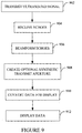
- Figure 9 illustrates a method
- an US probe transmits an ultrasound beam into a field of view.
- the probe incudes a transducer array according to the present invention.
- Transmission can be achieved via a five or other level FM transmitter and/or otherwise. Transmission can be tailored for image quality or frame rate based on a user input, as discussed herein.
- echoes generated in response thereto are received by the probe.
- the echoes are beamformed.
- the delays can be determined as discussed herein, including using a layered model to correct for the propagation path and propagation delay.
- a synthetic transmit aperture is created.
- the scan converter converts the processed echoes to data for display on a monitor.
- the data is displayed.
- the above may be implemented by way of computer readable instructions, encoded or embedded on computer readable storage medium, which, when executed by a computer processor(s), cause the processor(s) to carry out the described acts. Additionally or alternatively, at least one of the computer readable instructions is carried by a signal, carrier wave or other transitory medium.
Landscapes
- Engineering & Computer Science (AREA)
- Physics & Mathematics (AREA)
- Health & Medical Sciences (AREA)
- Life Sciences & Earth Sciences (AREA)
- Radar, Positioning & Navigation (AREA)
- Remote Sensing (AREA)
- Acoustics & Sound (AREA)
- Nuclear Medicine, Radiotherapy & Molecular Imaging (AREA)
- Animal Behavior & Ethology (AREA)
- Veterinary Medicine (AREA)
- Public Health (AREA)
- Biophysics (AREA)
- General Health & Medical Sciences (AREA)
- Pathology (AREA)
- Radiology & Medical Imaging (AREA)
- Biomedical Technology (AREA)
- Heart & Thoracic Surgery (AREA)
- Medical Informatics (AREA)
- Molecular Biology (AREA)
- Surgery (AREA)
- Computer Networks & Wireless Communication (AREA)
- General Physics & Mathematics (AREA)
- Gynecology & Obstetrics (AREA)
- Multimedia (AREA)
- Ultra Sonic Daignosis Equipment (AREA)
- Investigating Or Analyzing Materials By The Use Of Ultrasonic Waves (AREA)
Description
- The following generally relates to imaging and finds particular application to ultrasound imaging and is described herein with particular attention to an ultrasound imaging system.
- Ultrasound (US) imaging has provided useful information about the interior characteristics (e.g., organ tissue, material flow, etc.) of a subject under examination. A general US system includes a probe (with a transducer array) that interfaces with a console, which controls the transducer elements of the transducer array to transmit an ultrasonic beam and receive echoes produced in response thereto, which are processed to generate an image(s) of the interior characteristics. The detail and contrast resolutions of the imaging system depend at least on the shape of the ultrasonic beam, which has dimensions both in the imaging plane (azimuth or lateral) and across the imaging plane (elevation).
- A one dimensional (1D) transducer array includes a single row of transducer elements arranged along the lateral direction, and the beam is electronically controlled in the lateral direction. The width of the transducer elements is on the order of a wave length. By controlling the delays and weight coefficients in the beamforming, the focus can be controllably moved along a line. In the elevation direction, the height has been several millimeters (e.g., 4 to 20 mm). The focusing in the elevation plane is achieved with acoustic lenses, and the focus is generally fixed. The beam is narrowest at the elevation focus and diverges beyond it. Close to the transducer, the beam is as wide as the transducer array, and away from the elevation focus, the beam becomes even wider.
- A 1.5D array has several rows of elements. The effective size of the elements in elevation direction is usually much larger than the width. The outer rows are electrically connected to the middle row. A switch alternately couples outer rows to the middle row, depending on the distance from the transducer surface, creating large elements at large depths. Such arrays have had acoustic lenses that focus the beam in elevation direction. Unfortunately, there is no control over the delays in the elevation plane so there is a trade-off between beam size and the uniformity in the elevation plane. 1.75D array is similar to a 1.5D array, but each element is connected to a channel. This allows electronic focusing in the elevation direction. Unfortunately, the number of channels increases, e.g., from N to 2N, relative to a 1.5D array with N channels.
- A synthetic transmit aperture has been used to increase image quality. In one instance, this includes sequentially actuating two or more of the transduce elements, invoking transmissions of two or more ultrasound signals, where the echoes generated in response to each transmission have different phase and/or amplitude information. For each transmission, all of the transducer elements receive echoes, which are beamformed to generate a lower resolution image for each set of received echoes. The lower resolution images are accumulated and/or otherwise combined to generate a higher resolution image. Generally, a higher number of transmissions results in higher image quality, but lower frame rate. Therefore, unfortunately, there is a trade-off between image quality and frame rate.
- Coded excitation has been used to increase the signal-to-noise ratio. Examples of spread codes include, but are not limited to, Barker codes, Golay codes, and frequency modulated (FM) pulses. FM modulated pulses tend to be robust to frequency-dependent attenuation and, in many cases, gives the greatest increase in signal-to-noise ratio. An artifact of using FM pulses is the existence of range side-lobes (along the imaging direction). These range side lobes are attenuated by tapering the rising and falling edges of the FM pulse. Typically, a Tukey windowing function is used. This means that the transmitted pulses are both frequency and amplitude modulated. Sending such pulses usually requires either a multi-level linear sender (e.g. 12-bit) or bipolar square wave ([-1, 0, 1]) operating at over 200 MHz clock frequency. Unfortunately, such transmitters tend to be costly.
- Obese patients, generally, have a thicker layer of subcutaneous adipose tissue, relative to non-obese patients. The speed of sound in adipose tissue is on the order of 1450 m/s, while the speed of sound in organ tissue tends to be higher. For example, the speed of sound in liver tissue is on average about 1540 m/s. The sound waves refract during their propagation (Snell's law). Delay calculations for beamforming have been based on straight lines of propagation. Unfortunately, this is not an accurate assumption in the case of layered media including adipose tissue and organ tissue.
- Ultrasound imaging systems are already known in the state of art. For example,
WO-A-2009/020617 discloses an ultrasound imaging system including a transducer array to send and receive ultrasound pulses, a multi-focal lens structure, a multiplexing structure and a beamformer. For example, DAFT C M W ET AL: "A 1.5D transducer for medical ultrasound", ULTRASONICS SYMPOSIUM, 1994. PROCEEDINGS., 1994, IEEE CANNES, FRANCE 1-4 NOV. 1994, NEW YORK, NY, USA, IEEE, 31 October 1994, pages 1491-1495 vol. 3, XP032084619, DOI: 10.1109/ULTSYM.1994.401873 discloses a linear, non-rectangular transducer array. - Aspects of the application address the above matters, and others.
- The present invention is defined in the independent claim, and the preferable features according to the present application are defined in the dependent claims.
- The application is illustrated by way of example and not limitation in the figures of the accompanying drawings, in which like references indicate similar elements and in which:
-
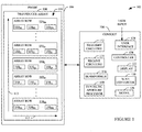
Figure 1 illustrates an example ultrasound imaging system; -
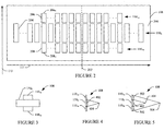
Figure 2 illustrates an example of the transducer array with a physical non-rectangular array; -
Figure 3 illustrates the footprint of the transducer array ofFigure 2 ; -
Figure 4 illustrates a side view of the transducer array ofFigure 2 in connection with a single focusing lens; -
Figure 5 illustrates a side view of the transducer array ofFigure 2 in connection with multiple focusing lenses and does not form part of the present invention; -
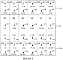
Figure 6 illustrates an example of the transducer array with a virtual non-rectangular array and does not form part of the present invention; -
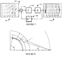
Figure 7 illustrates an example multi-level transmitter; -
Figure 8 illustrates an example diagram; and -
Figure 9 illustrates an example method. -
Figure 1 schematically illustrates anexample imaging system 102, such as ultrasonic (US) imaging system. Theimaging system 102 includes anultrasound transducer probe 104 and aconsole 106. Theultrasound transducer probe 104 interfaces with theconsole 106 through a suitable interface. - The
ultrasound transducer probe 104 includes a two-dimensional (2D)transducer array 108. Generally, thetransducer array 108 converts an electrical signal to an ultrasound pressured field and vice versa. More specifically, the elements of the rows are configured to transmit ultrasound signals in a field of view and receive echo signals generated in response to an interaction of the transmit ultrasound signals with structure in the field of view. Thetransducer array 108 is linear and can be fully populated, sparse, etc. - The illustrated
transducer array 108 includes N rows 110 (where N is an integer equal to or greater than three, such as 3, 5, 9, 11, etc.), including acenter row 110C and pairs ofouter rows 1101a and 1101b (collectively referred to herein as first pair of outer rows 1101),..., 110Ma and 110Mb (collectively referred to herein as Mth pair of outer rows 110M), where C, a, b, and M are integers. Thecenter row 110c includes I elements, 110C1, 110c2, ..., 110CI, where I is an integer. The first pair ofouter rows 1101 includes J elements, 11011, 11012, ..., 1101J, ..., and the pairs ofouter rows 110M includes K elements, 110M1, 110M2, ..., 110MK, where J and K are integers. - Each of the
rows 110 is arranged along alateral direction 111 of thetransducer array 108, with therows 110 arranged generally parallel to each other along anelevation direction 113 of thetransducer array 108. Therows rows 1101 are arranged on opposite sides of thecenter row 110c. A next pair of rows 110 (not visible) is arranged on opposite sides of the first pair ofrows 1101, ..., and therows rows 110M are arranged on opposite sides of an (M-1)th pair of row 110 (not visible). Note that the illustrated geometry (e.g., width and height) is for explanatory purposes and does not correspond to the actual geometry. - As described in greater detail below, the elements of the
transducer array 108, in aggregate, have a non-rectangular shape (e.g., a generally elliptical shape) in that thecenter row 110c includes more elements than theouter rows transducer array 108 with acenter row 110c that is populated with more elements than therows - The
console 106 includes transmitcircuitry 112 that selectively actuates or excites one or more of the transducer elements of thetransducer array 108. More particularly, the transmitcircuitry 112 generates a set of pulses (or a pulsed signal) that are conveyed to thetransducer array 108. The set of pulses actuates a set of the transducer elements of thetransducer array 108, causing the elements thereof to transmit ultrasound signals into an examination or scan field of view. As described in greater detail below, in one instance, the transmitcircuitry 108 is configured for coded excitations, which may facilitate improving the signal to noise ratio, relative to a configuration without coded excitations. - Receive
circuitry 114 receives a set of echoes (or echo signals) generated in response to the transmitted ultrasound signals. The echoes, generally, are a result of the interaction between the emitted ultrasound signals and the object (e.g., flowing blood cells, organ cells, etc.) in the scan field of view. The receivecircuit 116 may be configured for spatial compounding, filtering (e.g., FIR and/or IIR), and/or other echo processing. - A
beamformer 116 processes the received echoes, e.g., by applying time delays and weights to the echoes and summing the resulting echoes. As described in greater detail below, in one instance thebeamformer 116 utilizes a layered model to solve Snell's law and correct for propagation path and/or propagation delays. As such, thesystem 102 may provide for better focusing, which results in higher penetration depth, higher contrast resolution and higher detail resolution, with a fast calculation time. - An optional
synthetic aperture processor 118 is configured to generate a synthetic transmit and/or receive aperture. For synthetic transmit receive aperture, thesynthetic aperture processor 118 accumulates lower resolution beamformed echoes with different phase and/or amplitude information, generating a higher resolution image. A synthetic transmit aperture can be used to increase image quality, e.g., signal-to-noise ratio, contrast and detail resolution, etc. Generally, the higher the number of transmissions, the higher the image quality and the lower the frame rate. - A
scan converter 120 scan converts the data for display, e.g., by converting the beamformed data to the coordinate system of a display or display region used to visually present the resulting data. The illustrated embodiment includes adisplay 122. However, thedisplay 120 may alternatively be a remote device interfaced with theconsole 106. Visual presentation may be through an interactive graphical user interface (GUI), which allows the user to selectively rotate, scale, and/or manipulate the displayed data. - A user interface (UI) 124 include one or more input devices (e.g., a button, a knob, a slider, etc.) and/or one or more output devices (e.g., a display, etc.), which allows for interaction between with the
system 102. In one instance, the UI includes a software based and/or physical control that allows a user to select between higher image quality or high frame rate. The control activates/deactivates thesynthetic aperture processor 118 and/or determines, based on a predetermined protocol, user input or otherwise, the number of transmissions and hence the trade-off between image quality and frame rate. - The UI control gives the user control over the tradeoff between image quality and frame rate, allowing the user to determine the focusing strength of transmission. Generally, the minimum number of transmissions is two. The shape of transmit beam determines the weighting coefficients applied onto the beams. In this example, the
synthetic aperture processor 118 can employ amodel 126 from a plurality of models, each for a different beam shape, from a bank of models, depending on the beam shape, to determine the weighting coefficients applied onto the beams. - A
controller 128 controls the various components of theimaging system 102. For example, such control may include actuating or exciting individual or groups of transducer elements of thetransducer array 108 for an A-mode, B-mode, C-plane, and/or other data acquisition mode, steering and/or focusing the transmitted signal, etc., actuating thetransducer array 108 for steering and/or focusing the received echoes, etc. - The
console 106 may include one or more processors that execute one or more computer readable instructions encoded or embedded on computer readable storage medium such as physical memory and other non-transitory medium. Additional or alternatively, the instructions can be carried in a signal, carrier wave and other transitory or non- computer readable storage medium. In one instance, executing the instructions, in connection with the one or more processors, implements one or more of thebeamformer 116, thesynthetic aperture 118, and/or other components of theimaging system 102. - As briefly discussed above, the
transducer array 108 includes a multi-rowed non-rectangular footprint.Figures 2, 3, 4 and 5 illustrate a non-limiting example of thetransducer array 108.Figure 2 shows a view looking into atransducing face 200 of thetransducer array 108,Figure 3 illustrates a view looking into thetransducer array 108,Figure 4 illustrates a side view of thetransducer array 108 in connection with a focusing lens, andFigure 5 illustrates a side view of thetransducer array 108 in connection with multiple focusing lenses.Figure 5 is used for descriptive purposes only and does not form part of the present invention. - For sake of brevity, the
transducer array 108 is discussed in connection with a configuration in which N =3 forFigures 2 to 5 . In other embodiments, N > 3. Initially referring toFigure 2 , again, thecenter row 110c and theouter rows elevation direction 113 and each extends along thelateral direction 111, with theouter rows center row 110c. As shown, in this example, each of therows lateral direction 111 about an imaginarycentral axis 202. - Widths (lateral direction) of the individual elements 204 (110C1, 110c2, ..., 110CI in
Figure 1 ), 206 (11011, 11012, ..., 1101J inFigure 1 ) and 208 (110M1, 110M2, ..., 110MK inFigure 1 ) in therows lateral direction 111 is given by the number of elements being used. - In this example, heights (elevation direction) of the individual elements in the
rows row 110c. With equal widths and half the height, the area of a pair of elements of therows row 110c, and the electrical impedance is the same. In a variation, the heights of theelements rows elements 204 inrow 110c. The total height of all three rows combined is in a range of ten (10) to fifty (50) millimeters (mm). - Each of the
individual elements 204 of thecenter row 110c is in electrical communication with a different single channel. Each complementary pair of elements of theouter rows 1101a and 1101b (e.g., 206I and 208I) is in electrical communication with a different single channel. Generally, a complementary pair includes the elements along a same column as the particular center row element. Thus, there is a single channel for eachelement 204 and a single channel for each complementary pair ofelements elements elevation direction 113. - In the illustrated example, J = ½ I, where, from
Figure 1 , J represents the number ofelements outer rows elements 204 in thecenter row 110c. As such, thetransducer array 108 utilizes a total of 1.51 channels. For instance, where I = 32, J = 16, I = 128, J = 64, I = 192, J = 96, etc., thetransducer array 108 utilizes 48, 192, 288, etc. channels. As such, the illustratedtransducer array 108 utilizes less channels than a 1.75D transducer array or other configuration in which J = I. In other embodiments, I and J could be other values. In addition, J could be another factor of I such as ¼, ¾, etc. - With the configuration of
Figure 2 , thetransducer array 108 has a non-rectangular shape, for example, a generally elliptical shape, as shown in this example. This configuration provides a uniformly narrow beam in theelevation direction 113. - Turning to
Figures 3 and 4 , according to the invention, alens 402 such as an acoustic or other lens focuses the beam of thecenter row 110c at afocus distance 404. With respect toFigures 3 and 5 , in another embodiment which does not form part of the present invention, thelens 402 focuses the beam of themiddle row 110c at thefirst focus distance 404, andlenses 502, such as Fresnel lenses, focus the beam from theouter rows transducer array 102 than thefirst focus distance 404. - In one instance, the focus distances 404 and 504 are such that the focusing number (f-number) is approximately the same. An example of a suitable f-number is in a range from five (5) to eight (8). It is to be appreciated that having approximately equal f-numbers facilitates producing a beam with a uniform shape. The delays applied to the elements in the
outer rows - Although
Figures 2, 3, 4 and 5 describe thetransducer array 108 in a connection with three rows, it is to be understood that thetransducer array 108 could be a phased array having more rows. By way of example, where there are 5 rows and 192 channels, the center row may have 128 elements, whereas each of the outer rows would have 32 elements. In another example, the center row may have 96 elements, each of a first set of outer rows would have 64 elements, and each of a second pair of outer rows would have 32 elements. Other configurations are also contemplated herein. - In
Figures 2-5 , thetransducer array 102 includes a multi-rowed non-rectangular footprint that provides a uniformly narrow beam in theelevation direction 113. One or more focusing lenses are utilized with a subset (i.e. the central row) of the rows (Figure 4 ) and, in another embodiment which does not form part of the present invention, one or more Fresnel lenses can be utilized with other subsets of the rows (Figure 5 ). This configuration allows for achieving elevation focusing with a lower number of channels relative to a multi-rowed rectangular footprint and/or creating a narrow beam in elevation direction both close to and far from thetransducer array 108. -
Figure 6 schematically illustrates another example of thetransducer 108 which does not form part of the present invention. However, in this example, thetransducer array 108 includes a multi-rowed rectangular footprint (with the same number of elements in each row). For explanatory purposes, the following will be described for a 192 element per row, 3 rows (576 elements in aggregate), 192channel transducer array 108. Furthermore, the widths of theelements elements outer rows elements 204 of thecenter row 110c. - In the illustration, the elements of the
center row 110C are indexed 1:192 and divided up into blocks of 32 elements, or blocks 602, 604, 606, 608, 610 and 612.Reference numerals block 602, indexed 1:32, are respectively electrically connected, through multiplexers or the like, to channels 1:32, and so on for the remaining blocks, elements and channels.Reference numerals - The outer two
rows reference numerals block 626, indexed 1:32, are respectively electrically connected, through multiplexers or the like, to channels 97:128, and so on for the remaining blocks, elements and channels.Reference numerals - This configuration allows for an active aperture of 192 elements (or other number of elements) along the
center row 110c, e.g., at small depths where theouter rows center row 110c and elements of bothouter rows - For example, in one instance, elements 33:160 (616-622) of the
center row 110c are electrically connected to channels 33:160 (628-634), and elements 1:32 (614) of bothouter rows outer rows Figures 2-5 . Likewise, this configuration provides a uniformly narrow beam in theelevation direction 113. - It is to be appreciated that this particular assignment of elements to channels is not limiting. In addition, group sizes can be different, and individual elements can be assigned on an individual and not group basis. Moreover, one or more of the rows may have more or less than 192 elements, and there may be more or less than 192 channels.
- Generally, this configuration introduces an offset in the channel connections for the outer two
rows transducer array 102. Moreover, this configuration allows for angular compounding. - As discussed above, the transmit
circuitry 112 can be configured for coded excitations.Figure 7 schematically illustrates an example N-level (N ≥ 5)transmitter 702 for coded excitations that is based on a first-order sigma-delta modulator. As shown, thetransmitter 702 includes an analog to digital (A/D)converter 704 that quantizes aninput signal 706 summed with a negative of aprevious output signal 708, producing acurrent output signal 710 having a value of -1, ½, 0, ½, or 1, which drives the elements of thetransducer array 108. The 5-level quantized output signal over time is shown at 710. - The illustrated
transmitter 702 is a 5-level transmitter. Such coding allows for creating FM pulses at less than 200 MHz, such as 150 MHz, 120 MHz, 100 MHz and/or other frequency. In one instance, the performance of such a system will be approximately identical to a 3-level, bipolar square wave transmitters operating at 200 MHz, when imaging obese-patients, but at a lower cost. For example, thetransmitter 702 can achieve a same quality of received signal as with linear transmitters, but costs less. - The
transmitter 702 can be implemented as part of the transmitcircuitry 112, thecontroller 126, another distinct component of theconsole 106, and/or other component of theconsole 106 and/or remote from theconsole 106. - As discussed above, the
beamformer 116 may utilize a layered model to solve Snell's law and correct for the propagation path and propagation delay. The following describes a non-limiting approach. An example parameterized delay function is illustrated in EQUATION 1:

- The cos(φ) term to be found for each element position need not to be evaluated directly but can be found using the addition formulas for trigonometric functions. For example, the cos(2φ) term can be found using the properties cos(2φ) = cos2 (φ) - sin2 (φ). α and β can be estimated to minimize a difference between TSnell and T(φ) over a range of values for which
EQUATION 1 is used to estimate the delays. Ideally this minimization is done as a least square or a min-max optimization, but useful results can also be obtained from just two known delays suitably distributed over the entire range. - For example, α and β can be estimated for the range φ = 0, ..., φ 0 as follows.
- 1) With reference to
Figure 8 , find the sine to the angle, θ 0, that corresponds to the line from P1 to P0 based on EQUATION 2:
- 2) Find the angle, φ 1, that corresponds to tracing from P1 with θ 0 as starting angle, as shown in EQUATION 3:

- 3) Calculate the delay, τ1, as shown in EQUATION 4:

- 4) Repeat step 2) and 3) for another value


- 5) Inserting these values in EQUATION 2 and reorganizing renders EQUATION 10:

- 6) Calculate α and β as shown in EQUATIONS 11 and 12:


- This solution may provide for better focusing, which results in higher penetration depth, higher contrast resolution and higher detail resolution. Furthermore, the solution has a fast calculation time, which allows for better interactions with the user. The
beamformer 116 can be configured to calculate beamforming delays based on predetermined criteria, for example, such as every time the setup of the ultrasound system 100 changes the setup (e.g., line density, combination of modes - CFM/Doppler/THI/CHI, etc.). -
Figure 9 illustrates a method. - Note that the ordering of the following acts is for explanatory purposes and is not limiting. As such, one or more of the acts can be performed in a different order, including, but not limited to, concurrently. Furthermore, one or more of the acts may be omitted and/or one or more other acts may be added.
- At 902, an US probe transmits an ultrasound beam into a field of view.
- The probe incudes a transducer array according to the present invention. Transmission can be achieved via a five or other level FM transmitter and/or otherwise. Transmission can be tailored for image quality or frame rate based on a user input, as discussed herein.
- At 904, echoes generated in response thereto are received by the probe.
- At 906, the echoes are beamformed.
- Where the echoes are delayed, the delays can be determined as discussed herein, including using a layered model to correct for the propagation path and propagation delay.
- At 908, optional, a synthetic transmit aperture is created.
- At 910, the scan converter converts the processed echoes to data for display on a monitor.
- At 912, the data is displayed.
- The above may be implemented by way of computer readable instructions, encoded or embedded on computer readable storage medium, which, when executed by a computer processor(s), cause the processor(s) to carry out the described acts. Additionally or alternatively, at least one of the computer readable instructions is carried by a signal, carrier wave or other transitory medium.
Claims (6)
- An ultrasound imaging system (102), comprising:a linear transducer array (108) including a two-dimensional non-rectangular array of rows (110) of elements, wherein the two-dimensional non-rectangular array of rows (110) comprises:a center row (110C) of elements with a first number of elements;a first outer row (1101a) of elements with a second number of elements; anda second outer row (1101b) of elements with the second number of elements, the first outer row (1101a) and the second outer row (1101b) being located on opposite sides of the center row (110C),wherein the first outer row (1101a), the second outer row (1101b) and the center row (110C) are arranged to be parallel to one another along an elevation direction (113) of the transducer array with the first outer row (1101a), the second outer row (1101b) and the center row (110C) being arranged to extend along a lateral direction (111) of the transducer array,wherein the first number of elements of the center row (110C) is greater than the second number of elements of the first and second outer rows (1101a, 1101b), the center row (110C) being configured to be populated with more elements than each of the first and second outer rows (1101a, 1101b);transmit circuitry (112) configured for actuating the elements to transmit an ultrasound signal into a field of view;receive circuitry (114) configured for receiving echoes produced in response to an interaction between the ultrasound signal and a structure in the field of view; anda beamformer configured for processing the echoes to generate one or more scan lines indicative of the field of view,
characterized in that each element of the center row (110C) is in electrical communication with a different single channel, and each element of the first and second outer rows (1101a, 1101b) in the same column are configured to form a complementary pair of elements, each complementary pair being in electrical communication with a different single channel, and in that the ultrasound imaging system (102) comprises an acoustic lens (402) disposed on the center row (110c) of elements and configured to focus a first sub-portion of the signal that is transmitted by the center row (110c) at a first focus distance (404), wherein the first and second rows (1101a, 1101b) do not include an acoustic lens. - The system of claim 1, wherein the second number of elements is half the first number of elements.
- The system of claim 1 or 2, wherein the center row and the pair of rows are centered about a central axis (202) of the transducer array.
- The system of any of claims 1 to 3, the two-dimensional non-rectangular array of rows of elements, further comprising:
at least a second pair of rows (110Ma, 110Mb), including a third row located adjacent to the first row in the elevation direction and a fourth row located adjacent to the second row in the elevation direction, wherein the third and fourth rows each include a third number of elements. - The system of claim 4, wherein the third number of elements is half the second number of elements.
- The system of any of claims 1 to 5, wherein a width of the elements of the center and at least one pair of rows is approximately equal and height of the elements of the center row is approximately twice a height of the elements in the at least one pair of rows.
Applications Claiming Priority (1)
| Application Number | Priority Date | Filing Date | Title |
|---|---|---|---|
| PCT/IB2012/001823 WO2014045073A1 (en) | 2012-09-18 | 2012-09-18 | Ultrasound imaging |
Publications (2)
| Publication Number | Publication Date |
|---|---|
| EP2898345A1 EP2898345A1 (en) | 2015-07-29 |
| EP2898345B1 true EP2898345B1 (en) | 2021-10-06 |
Family
ID=47018269
Family Applications (1)
| Application Number | Title | Priority Date | Filing Date |
|---|---|---|---|
| EP12772413.6A Active EP2898345B1 (en) | 2012-09-18 | 2012-09-18 | Ultrasound imaging |
Country Status (4)
| Country | Link |
|---|---|
| US (2) | US10149663B2 (en) |
| EP (1) | EP2898345B1 (en) |
| JP (1) | JP2015528360A (en) |
| WO (1) | WO2014045073A1 (en) |
Families Citing this family (8)
| Publication number | Priority date | Publication date | Assignee | Title |
|---|---|---|---|---|
| WO2016039772A1 (en) * | 2014-09-12 | 2016-03-17 | Sound Technology Inc. | Two-dimensional ultrasound imaging transducer array with a non-rectangular active sensing region |
| CN111278363B (en) | 2017-10-16 | 2022-07-22 | 北京深迈瑞医疗电子技术研究院有限公司 | Ultrasonic imaging equipment, system and image enhancement method for ultrasonic contrast imaging |
| JP7350490B2 (en) * | 2019-02-01 | 2023-09-26 | キヤノンメディカルシステムズ株式会社 | Ultrasonic probe and ultrasound diagnostic equipment |
| US20200253585A1 (en) * | 2019-02-13 | 2020-08-13 | Butterfly Network, Inc. | Methods and apparatuses for collecting ultrasound images depicting needles |
| CN113950295A (en) * | 2019-06-14 | 2022-01-18 | 布弗莱运营公司 | Method and apparatus for collecting ultrasound data along different thickness guide angles |
| US20240225602A1 (en) * | 2021-12-23 | 2024-07-11 | Fujifilm Sonosite, Inc. | Multi-dimensional & multi-frequency ultrasound transducers |
| CN115184910B (en) * | 2022-09-13 | 2023-01-20 | 长江水利委员会水文局 | Method for correcting single-beam measurement beam angle effect of river channel section |
| US20250251503A1 (en) * | 2024-02-07 | 2025-08-07 | Wisconsin Alumni Research Foundation | Acoustic Subwavelength Imaging System |
Family Cites Families (13)
| Publication number | Priority date | Publication date | Assignee | Title |
|---|---|---|---|---|
| US6005916A (en) * | 1992-10-14 | 1999-12-21 | Techniscan, Inc. | Apparatus and method for imaging with wavefields using inverse scattering techniques |
| AU4169497A (en) * | 1996-08-29 | 1998-04-14 | David T. Borup | Apparatus and method for imaging with wavefields using inverse scattering techniques |
| US5882309A (en) * | 1997-05-07 | 1999-03-16 | General Electric Company | Multi-row ultrasonic transducer array with uniform elevator beamwidth |
| US6089096A (en) * | 1998-07-01 | 2000-07-18 | Aloka Co., Ltd. | Elevation focusing by beamformer channel sharing |
| US6183419B1 (en) * | 1999-02-01 | 2001-02-06 | General Electric Company | Multiplexed array transducers with improved far-field performance |
| US6352510B1 (en) * | 2000-06-22 | 2002-03-05 | Leonid S. Barabash | Ultrasound transducers for real time two and three dimensional image acquisition |
| US6821251B2 (en) * | 2002-12-18 | 2004-11-23 | Aloka Co., Ltd. | Multiplexer for connecting a multi-row ultrasound transducer array to a beamformer |
| ITRM20040300A1 (en) | 2004-06-18 | 2004-09-18 | Esaote Spa | INTERDIGITED GEOMETRY TRANSDUCER FOR THE OPTIMIZATION OF THE RADIATED SOUND BEAM. |
| US8366616B2 (en) * | 2005-05-09 | 2013-02-05 | Hitachi Medical Corporation | Ultrasonic diagnostic apparatus |
| JP4897370B2 (en) | 2006-06-28 | 2012-03-14 | 富士フイルム株式会社 | Ultrasonic transducer array, ultrasonic probe, ultrasonic endoscope, ultrasonic diagnostic equipment |
| US8323201B2 (en) * | 2007-08-06 | 2012-12-04 | Orison Corporation | System and method for three-dimensional ultrasound imaging |
| WO2010051108A2 (en) * | 2008-09-11 | 2010-05-06 | Lawrence Livermore National Security, Llc | Model-based tomographic reconstruction |
| JP5575554B2 (en) * | 2010-06-23 | 2014-08-20 | 株式会社東芝 | Ultrasonic diagnostic equipment |
-
2012
- 2012-09-18 WO PCT/IB2012/001823 patent/WO2014045073A1/en not_active Ceased
- 2012-09-18 EP EP12772413.6A patent/EP2898345B1/en active Active
- 2012-09-18 JP JP2015531653A patent/JP2015528360A/en active Pending
- 2012-09-18 US US14/428,672 patent/US10149663B2/en active Active
-
2018
- 2018-11-02 US US16/178,800 patent/US11452498B2/en active Active
Non-Patent Citations (1)
| Title |
|---|
| DAFT C M W ET AL: "A 1.5D transducer for medical ultrasound", ULTRASONICS SYMPOSIUM, 1994. PROCEEDINGS., 1994 IEEE CANNES, FRANCE 1-4 NOV. 1994, NEW YORK, NY, USA,IEEE, US, 31 October 1994 (1994-10-31), pages 1491 - 1495vol.3, XP032084619, ISBN: 978-0-7803-2012-3, DOI: 10.1109/ULTSYM.1994.401873 * |
Also Published As
| Publication number | Publication date |
|---|---|
| US10149663B2 (en) | 2018-12-11 |
| US20190150887A1 (en) | 2019-05-23 |
| WO2014045073A1 (en) | 2014-03-27 |
| JP2015528360A (en) | 2015-09-28 |
| US11452498B2 (en) | 2022-09-27 |
| US20150245812A1 (en) | 2015-09-03 |
| EP2898345A1 (en) | 2015-07-29 |
Similar Documents
| Publication | Publication Date | Title |
|---|---|---|
| US11452498B2 (en) | Ultrasound imaging | |
| EP1026663B1 (en) | Multiplexed array transducers with improved far-field performance | |
| US10705210B2 (en) | Three-dimensional (3-D) imaging with a row-column addressed (RCA) transducer array using synthetic aperture sequential beamforming (SASB) | |
| US6014897A (en) | Method and apparatus for improving sidelobe performance of sparse array using harmonic imaging | |
| US20140155751A1 (en) | Method and system for element-by-element flexible subarray beamforming | |
| US20050148874A1 (en) | Ultrasonic imaging aberration correction with microbeamforming | |
| WO2006134686A1 (en) | Ultrasonographic device | |
| JP2005152628A (en) | Method and apparatus for transmitting multiple beams | |
| US9791565B2 (en) | Multi-faced ultrasound transducer element | |
| US10792013B2 (en) | Three dimensional (3D) vector flow imaging with BiPlane phased array transducer | |
| Wei et al. | Sparse 2-D PZT-on-PCB arrays with density tapering | |
| US11402503B2 (en) | Two-dimensional ultrasound imaging transducer array with a non-rectangular active sensing region | |
| US20130303917A1 (en) | Ultrasound probe and ultrasound diagnosis apparatus | |
| US8235906B2 (en) | System and method for accelerated focused ultrasound imaging | |
| US8038620B2 (en) | Fresnel zone imaging system and method | |
| US10304226B2 (en) | Ultrasound focal zone system and method | |
| JP2004113693A (en) | Ultrasonic imaging instrument and ultrasonic imaging method | |
| JP7719780B2 (en) | Commandable parametric echo sounder and method for characterizing a sub-seafloor portion of an underwater environment - Patents.com | |
| Tanaka et al. | Tissue harmonic imaging with CMUT probe by amplitude modulation | |
| Schou et al. | Synthetic aperture sequential beamforming using spatial matched filtering | |
| JP2015521876A (en) | Ultrasound imaging | |
| Bouzari et al. | Improved focusing method for 3-D imaging using row-column-addressed 2-D arrays | |
| Chen et al. | A kerfless dual-layer transducer combined with beamforming by spatial matched filtering for high frame rate ultrasound imaging | |
| Kim et al. | Hybrid beamformation for volumetric ultrasound imaging scanners using 2-D array transducers | |
| WO2007039972A1 (en) | Ultrasonograph |
Legal Events
| Date | Code | Title | Description |
|---|---|---|---|
| PUAI | Public reference made under article 153(3) epc to a published international application that has entered the european phase |
Free format text: ORIGINAL CODE: 0009012 |
|
| 17P | Request for examination filed |
Effective date: 20150416 |
|
| AK | Designated contracting states |
Kind code of ref document: A1 Designated state(s): AL AT BE BG CH CY CZ DE DK EE ES FI FR GB GR HR HU IE IS IT LI LT LU LV MC MK MT NL NO PL PT RO RS SE SI SK SM TR |
|
| AX | Request for extension of the european patent |
Extension state: BA ME |
|
| DAX | Request for extension of the european patent (deleted) | ||
| STAA | Information on the status of an ep patent application or granted ep patent |
Free format text: STATUS: EXAMINATION IS IN PROGRESS |
|
| 17Q | First examination report despatched |
Effective date: 20170725 |
|
| GRAP | Despatch of communication of intention to grant a patent |
Free format text: ORIGINAL CODE: EPIDOSNIGR1 |
|
| STAA | Information on the status of an ep patent application or granted ep patent |
Free format text: STATUS: GRANT OF PATENT IS INTENDED |
|
| INTG | Intention to grant announced |
Effective date: 20210604 |
|
| GRAS | Grant fee paid |
Free format text: ORIGINAL CODE: EPIDOSNIGR3 |
|
| GRAA | (expected) grant |
Free format text: ORIGINAL CODE: 0009210 |
|
| STAA | Information on the status of an ep patent application or granted ep patent |
Free format text: STATUS: THE PATENT HAS BEEN GRANTED |
|
| AK | Designated contracting states |
Kind code of ref document: B1 Designated state(s): AL AT BE BG CH CY CZ DE DK EE ES FI FR GB GR HR HU IE IS IT LI LT LU LV MC MK MT NL NO PL PT RO RS SE SI SK SM TR |
|
| REG | Reference to a national code |
Ref country code: GB Ref legal event code: FG4D |
|
| REG | Reference to a national code |
Ref country code: CH Ref legal event code: EP Ref country code: AT Ref legal event code: REF Ref document number: 1436681 Country of ref document: AT Kind code of ref document: T Effective date: 20211015 |
|
| REG | Reference to a national code |
Ref country code: DE Ref legal event code: R096 Ref document number: 602012076859 Country of ref document: DE |
|
| REG | Reference to a national code |
Ref country code: IE Ref legal event code: FG4D |
|
| REG | Reference to a national code |
Ref country code: LT Ref legal event code: MG9D |
|
| REG | Reference to a national code |
Ref country code: NL Ref legal event code: MP Effective date: 20211006 |
|
| REG | Reference to a national code |
Ref country code: AT Ref legal event code: MK05 Ref document number: 1436681 Country of ref document: AT Kind code of ref document: T Effective date: 20211006 |
|
| PG25 | Lapsed in a contracting state [announced via postgrant information from national office to epo] |
Ref country code: RS Free format text: LAPSE BECAUSE OF FAILURE TO SUBMIT A TRANSLATION OF THE DESCRIPTION OR TO PAY THE FEE WITHIN THE PRESCRIBED TIME-LIMIT Effective date: 20211006 Ref country code: LT Free format text: LAPSE BECAUSE OF FAILURE TO SUBMIT A TRANSLATION OF THE DESCRIPTION OR TO PAY THE FEE WITHIN THE PRESCRIBED TIME-LIMIT Effective date: 20211006 Ref country code: FI Free format text: LAPSE BECAUSE OF FAILURE TO SUBMIT A TRANSLATION OF THE DESCRIPTION OR TO PAY THE FEE WITHIN THE PRESCRIBED TIME-LIMIT Effective date: 20211006 Ref country code: BG Free format text: LAPSE BECAUSE OF FAILURE TO SUBMIT A TRANSLATION OF THE DESCRIPTION OR TO PAY THE FEE WITHIN THE PRESCRIBED TIME-LIMIT Effective date: 20220106 Ref country code: AT Free format text: LAPSE BECAUSE OF FAILURE TO SUBMIT A TRANSLATION OF THE DESCRIPTION OR TO PAY THE FEE WITHIN THE PRESCRIBED TIME-LIMIT Effective date: 20211006 |
|
| PG25 | Lapsed in a contracting state [announced via postgrant information from national office to epo] |
Ref country code: IS Free format text: LAPSE BECAUSE OF FAILURE TO SUBMIT A TRANSLATION OF THE DESCRIPTION OR TO PAY THE FEE WITHIN THE PRESCRIBED TIME-LIMIT Effective date: 20220206 Ref country code: SE Free format text: LAPSE BECAUSE OF FAILURE TO SUBMIT A TRANSLATION OF THE DESCRIPTION OR TO PAY THE FEE WITHIN THE PRESCRIBED TIME-LIMIT Effective date: 20211006 Ref country code: PT Free format text: LAPSE BECAUSE OF FAILURE TO SUBMIT A TRANSLATION OF THE DESCRIPTION OR TO PAY THE FEE WITHIN THE PRESCRIBED TIME-LIMIT Effective date: 20220207 Ref country code: PL Free format text: LAPSE BECAUSE OF FAILURE TO SUBMIT A TRANSLATION OF THE DESCRIPTION OR TO PAY THE FEE WITHIN THE PRESCRIBED TIME-LIMIT Effective date: 20211006 Ref country code: NO Free format text: LAPSE BECAUSE OF FAILURE TO SUBMIT A TRANSLATION OF THE DESCRIPTION OR TO PAY THE FEE WITHIN THE PRESCRIBED TIME-LIMIT Effective date: 20220106 Ref country code: NL Free format text: LAPSE BECAUSE OF FAILURE TO SUBMIT A TRANSLATION OF THE DESCRIPTION OR TO PAY THE FEE WITHIN THE PRESCRIBED TIME-LIMIT Effective date: 20211006 Ref country code: LV Free format text: LAPSE BECAUSE OF FAILURE TO SUBMIT A TRANSLATION OF THE DESCRIPTION OR TO PAY THE FEE WITHIN THE PRESCRIBED TIME-LIMIT Effective date: 20211006 Ref country code: HR Free format text: LAPSE BECAUSE OF FAILURE TO SUBMIT A TRANSLATION OF THE DESCRIPTION OR TO PAY THE FEE WITHIN THE PRESCRIBED TIME-LIMIT Effective date: 20211006 Ref country code: GR Free format text: LAPSE BECAUSE OF FAILURE TO SUBMIT A TRANSLATION OF THE DESCRIPTION OR TO PAY THE FEE WITHIN THE PRESCRIBED TIME-LIMIT Effective date: 20220107 Ref country code: ES Free format text: LAPSE BECAUSE OF FAILURE TO SUBMIT A TRANSLATION OF THE DESCRIPTION OR TO PAY THE FEE WITHIN THE PRESCRIBED TIME-LIMIT Effective date: 20211006 |
|
| REG | Reference to a national code |
Ref country code: DE Ref legal event code: R097 Ref document number: 602012076859 Country of ref document: DE |
|
| PG25 | Lapsed in a contracting state [announced via postgrant information from national office to epo] |
Ref country code: SM Free format text: LAPSE BECAUSE OF FAILURE TO SUBMIT A TRANSLATION OF THE DESCRIPTION OR TO PAY THE FEE WITHIN THE PRESCRIBED TIME-LIMIT Effective date: 20211006 Ref country code: SK Free format text: LAPSE BECAUSE OF FAILURE TO SUBMIT A TRANSLATION OF THE DESCRIPTION OR TO PAY THE FEE WITHIN THE PRESCRIBED TIME-LIMIT Effective date: 20211006 Ref country code: RO Free format text: LAPSE BECAUSE OF FAILURE TO SUBMIT A TRANSLATION OF THE DESCRIPTION OR TO PAY THE FEE WITHIN THE PRESCRIBED TIME-LIMIT Effective date: 20211006 Ref country code: EE Free format text: LAPSE BECAUSE OF FAILURE TO SUBMIT A TRANSLATION OF THE DESCRIPTION OR TO PAY THE FEE WITHIN THE PRESCRIBED TIME-LIMIT Effective date: 20211006 Ref country code: DK Free format text: LAPSE BECAUSE OF FAILURE TO SUBMIT A TRANSLATION OF THE DESCRIPTION OR TO PAY THE FEE WITHIN THE PRESCRIBED TIME-LIMIT Effective date: 20211006 Ref country code: CZ Free format text: LAPSE BECAUSE OF FAILURE TO SUBMIT A TRANSLATION OF THE DESCRIPTION OR TO PAY THE FEE WITHIN THE PRESCRIBED TIME-LIMIT Effective date: 20211006 |
|
| PLBE | No opposition filed within time limit |
Free format text: ORIGINAL CODE: 0009261 |
|
| STAA | Information on the status of an ep patent application or granted ep patent |
Free format text: STATUS: NO OPPOSITION FILED WITHIN TIME LIMIT |
|
| 26N | No opposition filed |
Effective date: 20220707 |
|
| PG25 | Lapsed in a contracting state [announced via postgrant information from national office to epo] |
Ref country code: AL Free format text: LAPSE BECAUSE OF FAILURE TO SUBMIT A TRANSLATION OF THE DESCRIPTION OR TO PAY THE FEE WITHIN THE PRESCRIBED TIME-LIMIT Effective date: 20211006 |
|
| PG25 | Lapsed in a contracting state [announced via postgrant information from national office to epo] |
Ref country code: SI Free format text: LAPSE BECAUSE OF FAILURE TO SUBMIT A TRANSLATION OF THE DESCRIPTION OR TO PAY THE FEE WITHIN THE PRESCRIBED TIME-LIMIT Effective date: 20211006 |
|
| PG25 | Lapsed in a contracting state [announced via postgrant information from national office to epo] |
Ref country code: MC Free format text: LAPSE BECAUSE OF FAILURE TO SUBMIT A TRANSLATION OF THE DESCRIPTION OR TO PAY THE FEE WITHIN THE PRESCRIBED TIME-LIMIT Effective date: 20211006 |
|
| REG | Reference to a national code |
Ref country code: CH Ref legal event code: PL |
|
| GBPC | Gb: european patent ceased through non-payment of renewal fee |
Effective date: 20220918 |
|
| REG | Reference to a national code |
Ref country code: BE Ref legal event code: MM Effective date: 20220930 |
|
| PG25 | Lapsed in a contracting state [announced via postgrant information from national office to epo] |
Ref country code: IT Free format text: LAPSE BECAUSE OF FAILURE TO SUBMIT A TRANSLATION OF THE DESCRIPTION OR TO PAY THE FEE WITHIN THE PRESCRIBED TIME-LIMIT Effective date: 20211006 |
|
| PG25 | Lapsed in a contracting state [announced via postgrant information from national office to epo] |
Ref country code: LU Free format text: LAPSE BECAUSE OF NON-PAYMENT OF DUE FEES Effective date: 20220918 |
|
| P01 | Opt-out of the competence of the unified patent court (upc) registered |
Effective date: 20230528 |
|
| PG25 | Lapsed in a contracting state [announced via postgrant information from national office to epo] |
Ref country code: LI Free format text: LAPSE BECAUSE OF NON-PAYMENT OF DUE FEES Effective date: 20220930 Ref country code: IE Free format text: LAPSE BECAUSE OF NON-PAYMENT OF DUE FEES Effective date: 20220918 Ref country code: FR Free format text: LAPSE BECAUSE OF NON-PAYMENT OF DUE FEES Effective date: 20220930 Ref country code: CH Free format text: LAPSE BECAUSE OF NON-PAYMENT OF DUE FEES Effective date: 20220930 |
|
| PG25 | Lapsed in a contracting state [announced via postgrant information from national office to epo] |
Ref country code: BE Free format text: LAPSE BECAUSE OF NON-PAYMENT OF DUE FEES Effective date: 20220930 |
|
| PG25 | Lapsed in a contracting state [announced via postgrant information from national office to epo] |
Ref country code: GB Free format text: LAPSE BECAUSE OF NON-PAYMENT OF DUE FEES Effective date: 20220918 |
|
| PG25 | Lapsed in a contracting state [announced via postgrant information from national office to epo] |
Ref country code: HU Free format text: LAPSE BECAUSE OF FAILURE TO SUBMIT A TRANSLATION OF THE DESCRIPTION OR TO PAY THE FEE WITHIN THE PRESCRIBED TIME-LIMIT; INVALID AB INITIO Effective date: 20120918 |
|
| PG25 | Lapsed in a contracting state [announced via postgrant information from national office to epo] |
Ref country code: CY Free format text: LAPSE BECAUSE OF FAILURE TO SUBMIT A TRANSLATION OF THE DESCRIPTION OR TO PAY THE FEE WITHIN THE PRESCRIBED TIME-LIMIT Effective date: 20211006 |
|
| PG25 | Lapsed in a contracting state [announced via postgrant information from national office to epo] |
Ref country code: MK Free format text: LAPSE BECAUSE OF FAILURE TO SUBMIT A TRANSLATION OF THE DESCRIPTION OR TO PAY THE FEE WITHIN THE PRESCRIBED TIME-LIMIT Effective date: 20211006 |
|
| PG25 | Lapsed in a contracting state [announced via postgrant information from national office to epo] |
Ref country code: MT Free format text: LAPSE BECAUSE OF FAILURE TO SUBMIT A TRANSLATION OF THE DESCRIPTION OR TO PAY THE FEE WITHIN THE PRESCRIBED TIME-LIMIT Effective date: 20211006 |
|
| PGFP | Annual fee paid to national office [announced via postgrant information from national office to epo] |
Ref country code: DE Payment date: 20250820 Year of fee payment: 14 |
|
| PG25 | Lapsed in a contracting state [announced via postgrant information from national office to epo] |
Ref country code: TR Free format text: LAPSE BECAUSE OF FAILURE TO SUBMIT A TRANSLATION OF THE DESCRIPTION OR TO PAY THE FEE WITHIN THE PRESCRIBED TIME-LIMIT Effective date: 20211006 |