EP2898174B1 - Hands free gooseneck with rotating cartridge assemblies - Google Patents
Hands free gooseneck with rotating cartridge assemblies Download PDFInfo
- Publication number
- EP2898174B1 EP2898174B1 EP13773965.2A EP13773965A EP2898174B1 EP 2898174 B1 EP2898174 B1 EP 2898174B1 EP 13773965 A EP13773965 A EP 13773965A EP 2898174 B1 EP2898174 B1 EP 2898174B1
- Authority
- EP
- European Patent Office
- Prior art keywords
- flexible hose
- cartridge assembly
- coupled
- assembly
- gooseneck
- Prior art date
- Legal status (The legal status is an assumption and is not a legal conclusion. Google has not performed a legal analysis and makes no representation as to the accuracy of the status listed.)
- Active
Links
Images




Classifications
-
- E—FIXED CONSTRUCTIONS
- E21—EARTH OR ROCK DRILLING; MINING
- E21B—EARTH OR ROCK DRILLING; OBTAINING OIL, GAS, WATER, SOLUBLE OR MELTABLE MATERIALS OR A SLURRY OF MINERALS FROM WELLS
- E21B19/00—Handling rods, casings, tubes or the like outside the borehole, e.g. in the derrick; Apparatus for feeding the rods or cables
- E21B19/002—Handling rods, casings, tubes or the like outside the borehole, e.g. in the derrick; Apparatus for feeding the rods or cables specially adapted for underwater drilling
- E21B19/004—Handling rods, casings, tubes or the like outside the borehole, e.g. in the derrick; Apparatus for feeding the rods or cables specially adapted for underwater drilling supporting a riser from a drilling or production platform
- E21B19/006—Handling rods, casings, tubes or the like outside the borehole, e.g. in the derrick; Apparatus for feeding the rods or cables specially adapted for underwater drilling supporting a riser from a drilling or production platform including heave compensators
-
- E—FIXED CONSTRUCTIONS
- E21—EARTH OR ROCK DRILLING; MINING
- E21B—EARTH OR ROCK DRILLING; OBTAINING OIL, GAS, WATER, SOLUBLE OR MELTABLE MATERIALS OR A SLURRY OF MINERALS FROM WELLS
- E21B17/00—Drilling rods or pipes; Flexible drill strings; Kellies; Drill collars; Sucker rods; Cables; Casings; Tubings
- E21B17/01—Risers
-
- E—FIXED CONSTRUCTIONS
- E21—EARTH OR ROCK DRILLING; MINING
- E21B—EARTH OR ROCK DRILLING; OBTAINING OIL, GAS, WATER, SOLUBLE OR MELTABLE MATERIALS OR A SLURRY OF MINERALS FROM WELLS
- E21B17/00—Drilling rods or pipes; Flexible drill strings; Kellies; Drill collars; Sucker rods; Cables; Casings; Tubings
- E21B17/02—Couplings; joints
- E21B17/08—Casing joints
- E21B17/085—Riser connections
- E21B17/0853—Connections between sections of riser provided with auxiliary lines, e.g. kill and choke lines
-
- E—FIXED CONSTRUCTIONS
- E21—EARTH OR ROCK DRILLING; MINING
- E21B—EARTH OR ROCK DRILLING; OBTAINING OIL, GAS, WATER, SOLUBLE OR MELTABLE MATERIALS OR A SLURRY OF MINERALS FROM WELLS
- E21B19/00—Handling rods, casings, tubes or the like outside the borehole, e.g. in the derrick; Apparatus for feeding the rods or cables
- E21B19/002—Handling rods, casings, tubes or the like outside the borehole, e.g. in the derrick; Apparatus for feeding the rods or cables specially adapted for underwater drilling
- E21B19/004—Handling rods, casings, tubes or the like outside the borehole, e.g. in the derrick; Apparatus for feeding the rods or cables specially adapted for underwater drilling supporting a riser from a drilling or production platform
Definitions
- This disclosure relates generally to methods and apparatus for coupling a riser string to an offshore drilling rig. More specifically, this disclosure relates to methods and apparatus for coupling the auxiliary lines of a riser string to a drilling rig. Still more particularly, this disclosure relates to methods and apparatus that provide connections between the auxiliary lines of a riser that can be automatically repositioned so as to allow other equipment to be moved into and out of the moon pool of the offshore drilling rig.
- Offshore drilling rigs utilize drilling risers as the conduit between the drilling equipment at the surface and drilling equipment mounted on the seafloor.
- the drilling riser is a tubular conduit that serves as an extension of the wellbore from the equipment on the wellhead at the seafloor to the floating drilling rig.
- Conventional drilling risers include a primary tubular conduit and a plurality of smaller, higher pressure auxiliary conduits that are externally mounted to the primary tubular and provide conduits for choke, kill, and auxiliary fluid communication with the subsea blowout preventers.
- An example of prior art equipment is disclosed in US 5 727 630 .
- auxiliary conduits At the top of the riser string, these auxiliary conduits end in a terminal fitting that includes a plurality of goosenecks that connect to high pressure flexible hoses that are coupled to stationary piping on the drilling rig.
- the flexible hoses are necessary to compensate for the relative motion that occurs between the drilling rig and the riser.
- the flexible hoses Conventionally, during riser assembly, the flexible hoses are manually connected to the gooseneck by rig personnel that are often suspended over the moon pool during this process.
- gooseneck assemblies that can be connected to the auxiliary lines without manual intervention. These gooseneck assemblies can be coupled to the flexible hoses in a location away from the moon pool and can then be moved into position and coupled to the riser with minimum manual intervention. Once the gooseneck assembly is in position on the riser, the flexible hoses drape into the moon pool.
- a gooseneck assembly having a body disposed circumferentially about a portion of a riser string.
- a stab member is inwardly radially extendable relative to the body and engages a receptacle disposed on the riser string.
- a cartridge assembly engages the stab member and has a flexible hose coupling that is rotatable relative to a central axis of the stab member. The coupling is in fluid communication with the receptacle via the stab member.
- the assembly includes a actuator that is operable to rotate the flexible hose coupling relative to the central axis of the stab member.
- first and second features are formed in direct contact
- additional features may be formed interposing the first and second features, such that the first and second features may not be in direct contact.
- exemplary embodiments presented below may be combined in any combination of ways, i.e., any element from one exemplary embodiment may be used in any other exemplary embodiment, without departing from the scope of the disclosure.
- a riser termination assembly 10 includes a telescopic joint 12, a tension ring 14, a hands free gooseneck assembly 16, and a riser termination joint 18.
- the upper end 20 of the telescopic joint 12 includes a flange 22 that couples to a diverter (not shown) or to other equipment mounted to the drilling rig.
- the tension ring 14 includes a plurality of connection points 24 that allow for cables from the rig's tensioning equipment to be coupled to the tension ring so that the riser is held in tension as the rig moves due to wave action or other forces.
- the hands free gooseneck assembly 16 is supported by the tension ring 14 and includes auxiliary line cartridge assemblies 26 that provide fluid communication with the riser choke, kill, and auxiliary lines 28 and a connection coupling for flexible hoses 30 that are coupled to stationary piping on the drilling rig.
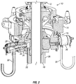
- FIG 2 illustrates a partial sectional view of the riser termination assembly 10 of Figure 1 .
- the cartridge assemblies 26 are mounted to the hands free gooseneck assembly 16 include stabs 32 project radially inward from the gooseneck assembly 16 and selectively engage receptacles 34 formed in the riser termination joint 18.
- the receptacles 34 are in fluid communication with the riser choke, kill, and auxiliary lines 28. Once engaged with the receptacles 34, the stabs 32 provide fluid communication between the riser lines 28 and the flexible hoses 30, which are coupled to the drilling rig.
- the riser termination assembly 10 is disposed within the moon pool of the drilling rig.
- the upper end 20 of the telescopic joint 12 moves with the rig and the tension ring 14, hands free gooseneck assembly 16, riser termination joint 18, and flexible hoses 30 move up and down relative to the rig.
- the flexible hoses 30 extend vertically downward from the cartridge assemblies 26 and then curve upward to their respective connections to the drilling rig. This "draping" of the flexible hoses 30 allows the tension ring 14 and hands free gooseneck assembly 16 to move relative to the drilling rig during operations.
- one or more of the cartridge assemblies 26 include a flexible hose coupling 29 that is rotatable about the central axis of the stab 32 so that the connection between the flexible hose 30 and the cartridge assembly 26 can be rotated relative to the gooseneck assembly 16.
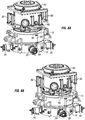
- Figures 3A and 3B illustrate a flexible hose 30 being rotated from an operational position ( Figure 3A ) to a stored position ( Figure 3B ). The bending radius of the flexible hose 30 will cause the hose to move substantially away from its original position as the cartridge assembly 26 is rotated.
- a variety of apparatus and systems may be used to rotate the cartridge assembly 26 and/or the flexible hose 30 between the operational and the stored positions.
- the flexible hose 30 may be fitted with a bend restrictor near the connection to the cartridge assembly 26 so as to maintain a desired bend radius.
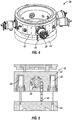
- a hands free gooseneck assembly 16 includes one or more actuators 40 disposed within the assembly body 42.
- the actuators 40 may be hydraulic cylinders, electrical actuators, or some other linear actuator.
- the actuators 40 selectively extend and retract an actuating ring 44 that is connected to the cartridge assemblies 26 via a flexible linkage 46.
- the flexible linkage 46 may include chains, geared linkage, wire rope, fiber rope, or other flexible material that can transmit torque to the cartridge assembly 26.
- the flexible linkage 46 wraps at least partially around and engages the rotatable portion of the cartridge assembly 26. As the actuators 40 extend, the linkage 46 applies torque to the cartridge assembly 26, rotating it in either the clockwise or counter-clockwise direction, dependent on the linkage installation. Retracting the actuators 40 allows the cartridge assembly 26 to rotate back to its original position.
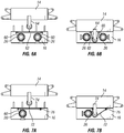
- the rotating portion of the cartridge assemblies 26 may include an actuation arm 60 that extends radially from the coupling and is coupled to a flexible link 62.
- An actuation bar 64 extends from the tension ring 14 and is adapted to engage the flexible link 62 as the tension ring is moved toward the gooseneck assembly 16. The engagement of the actuation bar 64 and the flexible link 62 pulls the opposed actuation arms 60 toward each other and causes the cartridge assemblies 26 to rotate.
- the flexible link 72 is coupled to a single actuation bar 74 and to a fixed point 76 on the gooseneck assembly 16.
- the flexible links 62 and 72 may include chains, geared linkage, wire rope, fiber rope, or other flexible material that can transmit torque onto the cartridge assembly 26.
- the hands free gooseneck 16 may be detached from the tension ring 14, lowered, and rotated such that the actuation arms 64, 74 are in line with the aforementioned linkages 62, 72.
- the hands free gooseneck 16 may then be raised back toward the tension ring 14 and locked in place.
- the action of raising the hands free gooseneck 16 causes the actuation arms 64, 74 to engage the flexible links 62, 72 and rotate cartridge assemblies 26.
- the angle of rotation may be controlled by the length of the actuation arms 64, 74 and associated flexible links 62, 72.
- the hands free gooseneck 16 When the hands free gooseneck 16 is detached from the tension ring 14 and lowered again, the cartridge assemblies 26 rotate back to their initial position.
- the hands free gooseneck 16 may be rotated out of line with the actuation arms 64, 74, raised, and locked to the tension ring 14 for storage.
- Figures 8A-B and 9A-B illustrate other alternative embodiments of a gooseneck assembly 16 where rotation of the cartridge assemblies 26 is accomplished through the use of a plurality of actuators 80.
- the actuators 80 can be mounted to the gooseneck assembly 16, the tension ring 14, or the diverter 82. When the actuators 80 extend, it provides an input to an actuating lever 84 that protrudes radially from the cartridge assemblies 26. The direction and angularity of rotation depend on the placement of the actuating lever 84 and stroke of the actuators 80. The actuators 80 can then be retracted to rotate the cartridge assemblies 26 back to the initial position.
- a pair of actuators 80 are coupled to the diverter 82 and engage a push bar 86 that is coupled to an upper end of a push rod 88.
- An intermediate cylinder 90 may be coupled to the tension ring 14 and provide further actuation force.
- the push rod 88 and/or intermediate cylinder 90 are coupled to an actuating lever 84 of a cartridge assembly 26. As the actuators 80 extend from the operating position shown in Figure 8A , the cartridge assembly 26 will rotate to the position shown in Figure 8B .
- Figures 9A and 9B illustrate an alternative embodiment wherein actuators 80 move an actuation ring 92 that is coupled to one or more cartridge assemblies 26 via a secondary linkage 94.
- the secondary linkage 94 is coupled to an actuating lever 84 that radially projects from the cartridge assembly 26.
- the actuators 80 may be mounted to the diverter 82 (as shown in Figure 9A ), to the gooseneck assembly 16 (as shown in Figure 9B ), or to the tension ring 14.
- the cylinder 80 As the cylinder 80 extends, it moves the actuating ring 92 downward, causing the linkage 94 to pull the actuating lever 84 and rotate the cartridge assembly 26.
- the direction and angularity of rotation depend on the placement of the actuating lever 84 and stroke of the actuators 80.
- the actuators 80 can be retracted to rotate the cartridge assembly 26 rotate back to its initial position.
- a hydraulic cylinder or other linear actuator, can be directly attached to a lever arm located on a cartridge assembly.
- the hydraulic cylinder can be attached to a fixed point on the hands free gooseneck assembly so that rotation of the cartridge assembly is accomplished by extending and retracting the cylinder, imparting a rotation determined by the stroke of the attached cylinder.
- the cartridge assembly may be rotated in either the clockwise or counter clockwise direction determined by location of the anchor point and configuration of the hydraulic cylinder.
- a cartridge assembly can include gear teeth that enable rotation of the cartridge assembly.
- the gear teeth can engage a rack other gears that can be actuated to impart a torque onto the cartridge assembly.
- a rack may be coupled to the geared cartridge assembly and actuated by a linear actuator.
- rotary actuators can be used to directly engage and rotate the geared cartridge assembly or may be coupled to the geared cartridge assembly via one or more intermediary gears.
- a multi-hinged mechanism 100 can be coupled to the flexible hose 30 to enable engagement with a tugger line or other pulling system available on the rig.
- the multi-hinged mechanism 100 conforms to the natural bend radius of the flexible hose 30 and is equipped with multiple pulling points 102.
- the mechanism 100 can be stored on one end of the flexible line 30 while not in use. When needed, the mechanism 100 can be pulled along the flexible hose 30 to a desired location. Utilizing one or more of the pull points 102, the cartridge assembly can then be rotated in a desired direction depending on the direction of pull.
- Rotation of a cartridge assembly can also be accomplished through stationary push bars mounted to the underside of the tension ring.
- the hands free gooseneck assembly can be detached from the tension ring and rotated by utilizing the top drive or other mechanism. As the gooseneck assembly rotates, the push bars react against and move the flexible hoses. The cartridge assemblies rotate as the flexible hoses are moved. Once the hoses are in the desired location, the hands free gooseneck assembly can then be raised back up to the tension ring and locked into place so that the flexible hoses remain in the desired position.
- the cartridge assemblies can be equipped with extendable reaction bars which protrude into well center. A tool could be lowered through well center to engage the reaction bars and rotate the cartridge assemblies using either rotation or axial movement of the tool.
Landscapes
- Engineering & Computer Science (AREA)
- Geology (AREA)
- Life Sciences & Earth Sciences (AREA)
- Mining & Mineral Resources (AREA)
- Physics & Mathematics (AREA)
- Environmental & Geological Engineering (AREA)
- Fluid Mechanics (AREA)
- Mechanical Engineering (AREA)
- General Life Sciences & Earth Sciences (AREA)
- Geochemistry & Mineralogy (AREA)
- Earth Drilling (AREA)
- Quick-Acting Or Multi-Walled Pipe Joints (AREA)
- Flexible Shafts (AREA)
Description
- This disclosure relates generally to methods and apparatus for coupling a riser string to an offshore drilling rig. More specifically, this disclosure relates to methods and apparatus for coupling the auxiliary lines of a riser string to a drilling rig. Still more particularly, this disclosure relates to methods and apparatus that provide connections between the auxiliary lines of a riser that can be automatically repositioned so as to allow other equipment to be moved into and out of the moon pool of the offshore drilling rig.
- Offshore drilling rigs utilize drilling risers as the conduit between the drilling equipment at the surface and drilling equipment mounted on the seafloor. The drilling riser is a tubular conduit that serves as an extension of the wellbore from the equipment on the wellhead at the seafloor to the floating drilling rig. Conventional drilling risers include a primary tubular conduit and a plurality of smaller, higher pressure auxiliary conduits that are externally mounted to the primary tubular and provide conduits for choke, kill, and auxiliary fluid communication with the subsea blowout preventers. An example of prior art equipment is disclosed in
US 5 727 630 . - At the top of the riser string, these auxiliary conduits end in a terminal fitting that includes a plurality of goosenecks that connect to high pressure flexible hoses that are coupled to stationary piping on the drilling rig. The flexible hoses are necessary to compensate for the relative motion that occurs between the drilling rig and the riser. Conventionally, during riser assembly, the flexible hoses are manually connected to the gooseneck by rig personnel that are often suspended over the moon pool during this process.
- Manufacturers have begun to offer gooseneck assemblies that can be connected to the auxiliary lines without manual intervention. These gooseneck assemblies can be coupled to the flexible hoses in a location away from the moon pool and can then be moved into position and coupled to the riser with minimum manual intervention. Once the gooseneck assembly is in position on the riser, the flexible hoses drape into the moon pool.
- When other equipment, such as the blowout preventer stack, needs to be moved through or into the moon pool, the flexible hoses often have to be moved out of the way to clear a path through the moon pool area. Conventional methods for moving the flexible hoses include simply pushing the flexible hoses out of the way with the equipment or manually moving the flexible hoses using tugger lines and winches. Each of these methods has drawbacks that can result in damage to equipment and exposing personnel to potential hazards.
- Thus, there is a continuing need in the art for methods and apparatus for facilitating the management of flexible hoses within the moon pool that overcome these and other limitations of the prior art.
- A gooseneck assembly having a body disposed circumferentially about a portion of a riser string. A stab member is inwardly radially extendable relative to the body and engages a receptacle disposed on the riser string. A cartridge assembly engages the stab member and has a flexible hose coupling that is rotatable relative to a central axis of the stab member. The coupling is in fluid communication with the receptacle via the stab member. The assembly includes a actuator that is operable to rotate the flexible hose coupling relative to the central axis of the stab member.
- For a more detailed description of the embodiments of the present disclosure, reference will now be made to the accompanying drawings, wherein:
-
Figure 1 is an elevation view of a riser termination assembly. -
Figure 2 is a partial sectional view of a riser termination assembly. -
Figures 3A and 3B are partial elevation views of a hands free gooseneck assembly having a rotatable coupling. -
Figure 4 is an isometric view of one embodiment of a hands free gooseneck assembly having rotatable cartridge assemblies. -
Figure 5 is a partial sectional view of the hands free gooseneck assembly ofFigure 4 . -
Figures 6A and 6B are partial elevation views of an alternative hands free gooseneck assembly having a rotatable coupling. -
Figures 7A and 7B are partial elevation views of an alternative hands free gooseneck assembly having a rotatable coupling. -
Figures 8A and 8B are partial elevation views of an alternative hands free gooseneck assembly having a rotatable coupling. -
Figures 9A and 9B are partial elevation views of an alternative hands free gooseneck assembly having a rotatable coupling. -
Figures 10A and 10B are partial elevation views of an alternative hands free gooseneck assembly having a rotatable coupling. - It is to be understood that the following disclosure describes several exemplary embodiments for implementing different features, structures, or functions of the invention. Exemplary embodiments of components, arrangements, and configurations are described below to simplify the present disclosure; however, these exemplary embodiments are provided merely as examples and are not intended to limit the scope of the invention. Additionally, the present disclosure may repeat reference numerals and/or letters in the various exemplary embodiments and across the Figures provided herein. This repetition is for the purpose of simplicity and clarity and does not in itself dictate a relationship between the various exemplary embodiments and/or configurations discussed in the various figures. Moreover, the formation of a first feature over or on a second feature in the description that follows may include embodiments in which the first and second features are formed in direct contact, and may also include embodiments in which additional features may be formed interposing the first and second features, such that the first and second features may not be in direct contact. Finally, the exemplary embodiments presented below may be combined in any combination of ways, i.e., any element from one exemplary embodiment may be used in any other exemplary embodiment, without departing from the scope of the disclosure.
- Additionally, certain terms are used throughout the following description and claims to refer to particular components. As one skilled in the art will appreciate, various entities may refer to the same component by different names, and as such, the naming convention for the elements described herein is not intended to limit the scope of the invention, unless otherwise specifically defined herein. Further, the naming convention used herein is not intended to distinguish between components that differ in name but not function. Additionally, in the following discussion and in the claims, the terms "including" and "comprising" are used in an open-ended fashion, and thus should be interpreted to mean "including, but not limited to." All numerical values in this disclosure may be exact or approximate values unless otherwise specifically stated. Accordingly, various embodiments of the disclosure may deviate from the numbers, values, and ranges disclosed herein without departing from the intended scope. Furthermore, as it is used in the claims or specification, the term "or" is intended to encompass both exclusive and inclusive cases, i.e., "A or B" is intended to be synonymous with "at least one of A and B," unless otherwise expressly specified herein.
- Referring initially to
Figure 1 , ariser termination assembly 10 includes atelescopic joint 12, atension ring 14, a handsfree gooseneck assembly 16, and ariser termination joint 18. Theupper end 20 of thetelescopic joint 12 includes aflange 22 that couples to a diverter (not shown) or to other equipment mounted to the drilling rig. Thetension ring 14 includes a plurality ofconnection points 24 that allow for cables from the rig's tensioning equipment to be coupled to the tension ring so that the riser is held in tension as the rig moves due to wave action or other forces. The handsfree gooseneck assembly 16 is supported by thetension ring 14 and includes auxiliaryline cartridge assemblies 26 that provide fluid communication with the riser choke, kill, andauxiliary lines 28 and a connection coupling forflexible hoses 30 that are coupled to stationary piping on the drilling rig. -
Figure 2 illustrates a partial sectional view of theriser termination assembly 10 ofFigure 1 . Thecartridge assemblies 26 are mounted to the handsfree gooseneck assembly 16 includestabs 32 project radially inward from thegooseneck assembly 16 and selectively engagereceptacles 34 formed in theriser termination joint 18. Thereceptacles 34 are in fluid communication with the riser choke, kill, andauxiliary lines 28. Once engaged with thereceptacles 34, thestabs 32 provide fluid communication between theriser lines 28 and theflexible hoses 30, which are coupled to the drilling rig. - In operation, the
riser termination assembly 10 is disposed within the moon pool of the drilling rig. As the rig moves, theupper end 20 of thetelescopic joint 12 moves with the rig and thetension ring 14, handsfree gooseneck assembly 16,riser termination joint 18, andflexible hoses 30 move up and down relative to the rig. Theflexible hoses 30 extend vertically downward from thecartridge assemblies 26 and then curve upward to their respective connections to the drilling rig. This "draping" of theflexible hoses 30 allows thetension ring 14 and handsfree gooseneck assembly 16 to move relative to the drilling rig during operations. - During certain operations it may be desirable to temporarily move the
flexible hoses 30 out of the moon pool to allow other equipment to pass into or through the area. To support this movement, one or more of thecartridge assemblies 26 include aflexible hose coupling 29 that is rotatable about the central axis of thestab 32 so that the connection between theflexible hose 30 and thecartridge assembly 26 can be rotated relative to thegooseneck assembly 16. As an example,Figures 3A and 3B illustrate aflexible hose 30 being rotated from an operational position (Figure 3A ) to a stored position (Figure 3B ). The bending radius of theflexible hose 30 will cause the hose to move substantially away from its original position as thecartridge assembly 26 is rotated. A variety of apparatus and systems may be used to rotate thecartridge assembly 26 and/or theflexible hose 30 between the operational and the stored positions. In certain embodiments, theflexible hose 30 may be fitted with a bend restrictor near the connection to thecartridge assembly 26 so as to maintain a desired bend radius. - Referring now to
Figures 4 and 5 , one embodiment of a handsfree gooseneck assembly 16 includes one ormore actuators 40 disposed within theassembly body 42. Theactuators 40 may be hydraulic cylinders, electrical actuators, or some other linear actuator. Theactuators 40 selectively extend and retract anactuating ring 44 that is connected to thecartridge assemblies 26 via aflexible linkage 46. Theflexible linkage 46 may include chains, geared linkage, wire rope, fiber rope, or other flexible material that can transmit torque to thecartridge assembly 26. Theflexible linkage 46 wraps at least partially around and engages the rotatable portion of thecartridge assembly 26. As theactuators 40 extend, thelinkage 46 applies torque to thecartridge assembly 26, rotating it in either the clockwise or counter-clockwise direction, dependent on the linkage installation. Retracting theactuators 40 allows thecartridge assembly 26 to rotate back to its original position. - As shown in
Figures 6A and 6B , in other embodiments, the rotating portion of thecartridge assemblies 26 may include anactuation arm 60 that extends radially from the coupling and is coupled to aflexible link 62. Anactuation bar 64 extends from thetension ring 14 and is adapted to engage theflexible link 62 as the tension ring is moved toward thegooseneck assembly 16. The engagement of theactuation bar 64 and theflexible link 62 pulls the opposedactuation arms 60 toward each other and causes thecartridge assemblies 26 to rotate. In an alternative embodiment, as shownFigures 7A and 7B , theflexible link 72 is coupled to asingle actuation bar 74 and to a fixedpoint 76 on thegooseneck assembly 16. Theflexible links cartridge assembly 26. - In operation, the hands
free gooseneck 16 may be detached from thetension ring 14, lowered, and rotated such that theactuation arms aforementioned linkages free gooseneck 16 may then be raised back toward thetension ring 14 and locked in place. As previously discussed, the action of raising the handsfree gooseneck 16 causes theactuation arms flexible links cartridge assemblies 26. The angle of rotation may be controlled by the length of theactuation arms flexible links free gooseneck 16 is detached from thetension ring 14 and lowered again, thecartridge assemblies 26 rotate back to their initial position. For storage, the handsfree gooseneck 16 may be rotated out of line with theactuation arms tension ring 14 for storage. -
Figures 8A-B and9A-B illustrate other alternative embodiments of agooseneck assembly 16 where rotation of thecartridge assemblies 26 is accomplished through the use of a plurality ofactuators 80. In the embodiments shown, theactuators 80 can be mounted to thegooseneck assembly 16, thetension ring 14, or thediverter 82. When theactuators 80 extend, it provides an input to anactuating lever 84 that protrudes radially from thecartridge assemblies 26. The direction and angularity of rotation depend on the placement of the actuatinglever 84 and stroke of theactuators 80. Theactuators 80 can then be retracted to rotate thecartridge assemblies 26 back to the initial position. - In
Figures 8A and 8B , a pair ofactuators 80 are coupled to thediverter 82 and engage apush bar 86 that is coupled to an upper end of apush rod 88. Anintermediate cylinder 90 may be coupled to thetension ring 14 and provide further actuation force. Thepush rod 88 and/orintermediate cylinder 90 are coupled to anactuating lever 84 of acartridge assembly 26. As theactuators 80 extend from the operating position shown inFigure 8A , thecartridge assembly 26 will rotate to the position shown inFigure 8B . -
Figures 9A and 9B illustrate an alternative embodiment whereinactuators 80 move anactuation ring 92 that is coupled to one ormore cartridge assemblies 26 via asecondary linkage 94. Thesecondary linkage 94 is coupled to anactuating lever 84 that radially projects from thecartridge assembly 26. Theactuators 80 may be mounted to the diverter 82 (as shown inFigure 9A ), to the gooseneck assembly 16 (as shown inFigure 9B ), or to thetension ring 14. As thecylinder 80 extends, it moves theactuating ring 92 downward, causing thelinkage 94 to pull theactuating lever 84 and rotate thecartridge assembly 26. The direction and angularity of rotation depend on the placement of the actuatinglever 84 and stroke of theactuators 80. Theactuators 80 can be retracted to rotate thecartridge assembly 26 rotate back to its initial position. - In certain embodiments, a hydraulic cylinder, or other linear actuator, can be directly attached to a lever arm located on a cartridge assembly. The hydraulic cylinder can be attached to a fixed point on the hands free gooseneck assembly so that rotation of the cartridge assembly is accomplished by extending and retracting the cylinder, imparting a rotation determined by the stroke of the attached cylinder. The cartridge assembly may be rotated in either the clockwise or counter clockwise direction determined by location of the anchor point and configuration of the hydraulic cylinder.
- In other embodiments, a cartridge assembly can include gear teeth that enable rotation of the cartridge assembly. The gear teeth can engage a rack other gears that can be actuated to impart a torque onto the cartridge assembly. A rack may be coupled to the geared cartridge assembly and actuated by a linear actuator. In other embodiments, rotary actuators can be used to directly engage and rotate the geared cartridge assembly or may be coupled to the geared cartridge assembly via one or more intermediary gears.
- In certain embodiments, the use of separate actuators and systems may not be desired and the cartridge assemblies, and their attached flexible hoses, can be rotated via other means. For example, as shown in
Figures 10A and 10B , amulti-hinged mechanism 100 can be coupled to theflexible hose 30 to enable engagement with a tugger line or other pulling system available on the rig. Themulti-hinged mechanism 100 conforms to the natural bend radius of theflexible hose 30 and is equipped with multiple pullingpoints 102. Themechanism 100 can be stored on one end of theflexible line 30 while not in use. When needed, themechanism 100 can be pulled along theflexible hose 30 to a desired location. Utilizing one or more of the pull points 102, the cartridge assembly can then be rotated in a desired direction depending on the direction of pull. - Rotation of a cartridge assembly can also be accomplished through stationary push bars mounted to the underside of the tension ring. The hands free gooseneck assembly can be detached from the tension ring and rotated by utilizing the top drive or other mechanism. As the gooseneck assembly rotates, the push bars react against and move the flexible hoses. The cartridge assemblies rotate as the flexible hoses are moved. Once the hoses are in the desired location, the hands free gooseneck assembly can then be raised back up to the tension ring and locked into place so that the flexible hoses remain in the desired position. In other embodiments, the cartridge assemblies can be equipped with extendable reaction bars which protrude into well center. A tool could be lowered through well center to engage the reaction bars and rotate the cartridge assemblies using either rotation or axial movement of the tool.
- While the disclosure is susceptible to various modifications and alternative forms, specific embodiments thereof are shown by way of example in the drawings and description. It should be understood, however, that the drawings and detailed description thereto are not intended to limit the disclosure to the particular form disclosed, but on the contrary, the intention is to cover all modifications, equivalents and alternatives falling within the scope of the appended claims.
Claims (6)
- A gooseneck assembly (16) comprising:a body operable to be disposed circumferentially about a portion of a riser string;a stab member (32) that is inwardly radially extendable relative to the body so as to engage a receptacle (34) disposed on the riser string;a cartridge assembly (26) engaged with the stab member and having a flexible hose coupling (29) that is rotatable relative to a central axis of the stab member, wherein the coupling is in fluid communication with the receptacle via the stab member;a flexible hose (30) having an end coupled to the flexible hose coupling (29); andan actuator (40, 80) operable to rotate the flexible hose coupling relative to the central axis of the stab member from an operational position wherein the flexible hose extends vertically downward from the flexible hose coupling to a stored position wherein the end of the flexible hose that is coupled to the flexible hose coupling is at an angle to vertical.
- The gooseneck assembly of claim 1, further comprising: an actuation arm (60) extending from the cartridge assembly, wherein the actuator is coupled to the actuation arm and the body.
- A gooseneck assembly (16) comprising:a body operable to be disposed circumferentially about a portion of a riser string;a cartridge assembly (26) rotatably coupled to the body;a stab member (32) engaged with the cartridge assembly and inwardly radially extendable relative to the body so as to engage a receptacle (34) disposed on the riser string;a flexible hose coupling (29) disposed on the cartridge assembly and in fluid communication with the receptacle via the stab member;a flexible hose (30) having an end coupled to the flexible hose coupling (29); andan actuator (40, 80) coupled to the cartridge assembly and operable to rotate the cartridge assembly relative to a central axis of the stab member from an operational position, wherein the flexible hose extends vertically downward from the flexible hose coupling, to a stored position wherein the end of the flexible hose that is coupled to the flexible hose coupling is at an angle to vertical.
- The gooseneck assembly of claim 3 further comprising:an actuation arm (60) extending from the cartridge assembly, wherein the actuator is coupled to the actuation arm and the body.
- A method comprising:coupling an end of a flexible hose (30) to a cartridge assembly (26) that is coupled to a body that is disposable circumferentially about a portion of a riser string;engaging a receptacle (34) disposed on the riser string with a stab member (32) that is engaged with the cartridge assembly; androtating the cartridge assembly about a central axis of the stab member from an operational position, wherein the flexible hose extends vertically downward from the cartridge assembly, to a stored position, wherein the end of the flexible hose that is coupled to the cartridge assembly is at an angle to vertical.
- The method of claim 5, wherein the cartridge assembly is rotated by extending an actuator (40, 80) that is coupled to an actuation arm (60) of the cartridge assembly.
Applications Claiming Priority (2)
| Application Number | Priority Date | Filing Date | Title |
|---|---|---|---|
| US201261704179P | 2012-09-21 | 2012-09-21 | |
| PCT/US2013/060631 WO2014047295A2 (en) | 2012-09-21 | 2013-09-19 | Hands free gooseneck with rotating cartridge assemblies |
Publications (2)
| Publication Number | Publication Date |
|---|---|
| EP2898174A2 EP2898174A2 (en) | 2015-07-29 |
| EP2898174B1 true EP2898174B1 (en) | 2016-12-07 |
Family
ID=49305146
Family Applications (1)
| Application Number | Title | Priority Date | Filing Date |
|---|---|---|---|
| EP13773965.2A Active EP2898174B1 (en) | 2012-09-21 | 2013-09-19 | Hands free gooseneck with rotating cartridge assemblies |
Country Status (6)
| Country | Link |
|---|---|
| US (1) | US9611704B2 (en) |
| EP (1) | EP2898174B1 (en) |
| BR (1) | BR112015005874B1 (en) |
| CA (1) | CA2884279C (en) |
| DK (1) | DK2898174T3 (en) |
| WO (1) | WO2014047295A2 (en) |
Families Citing this family (12)
| Publication number | Priority date | Publication date | Assignee | Title |
|---|---|---|---|---|
| US10294746B2 (en) * | 2013-03-15 | 2019-05-21 | Cameron International Corporation | Riser gas handling system |
| EP3080381B1 (en) * | 2013-12-11 | 2020-01-22 | National Oilwell Varco, L.P. | Wellsite cable support assembly and method of use |
| US9759018B2 (en) * | 2014-12-12 | 2017-09-12 | Hydril USA Distribution LLC | System and method of alignment for hydraulic coupling |
| GB201503844D0 (en) * | 2015-03-06 | 2015-04-22 | Oil States Ind Uk Ltd | Apparatus and method |
| US9828824B2 (en) * | 2015-05-01 | 2017-11-28 | Hydril Usa Distribution, Llc | Hydraulic re-configurable and subsea repairable control system for deepwater blow-out preventers |
| US10303819B2 (en) * | 2016-08-25 | 2019-05-28 | Drilling Info, Inc. | Systems and methods for allocating hydrocarbon production values |
| NL2019427B1 (en) * | 2017-08-18 | 2019-02-25 | Itrec Bv | Running a subsea riser string. |
| US10273766B1 (en) * | 2018-03-08 | 2019-04-30 | Jle Inovaçao Tecnologica Ltda Epp | Plug and play connection system for a below-tension-ring managed pressure drilling system |
| GB201815150D0 (en) | 2018-09-18 | 2018-10-31 | Oil States Ind Uk Ltd | Connection system for a marine drilling riser |
| US11603718B2 (en) | 2020-02-06 | 2023-03-14 | Schlumberger Technology Corporation | Gooseneck connector system |
| US11982134B2 (en) * | 2020-09-02 | 2024-05-14 | Schlumberger Technology Corporation | Drape hose quick connect for managed pressure drilling |
| US12320208B2 (en) * | 2023-02-01 | 2025-06-03 | Grant Prideco, Inc. | Hands-free gooseneck and hands-free gooseneck flow spool |
Family Cites Families (10)
| Publication number | Priority date | Publication date | Assignee | Title |
|---|---|---|---|---|
| ES368170A1 (en) * | 1968-08-28 | 1971-05-01 | Stang Corp John W | Improvements in swivel pipe joints and in water other liquid jet monitors incorporating such joints |
| US4403658A (en) | 1980-09-04 | 1983-09-13 | Hughes Tool Company | Multiline riser support and connection system and method for subsea wells |
| US4448568A (en) | 1982-06-22 | 1984-05-15 | Mobil Oil Corporation | Marine surface facility work station for subsea equipment handling |
| US4592426A (en) | 1984-12-10 | 1986-06-03 | Hughes Tool Company | Upper termination with sliding sleeve seals |
| US4712620A (en) * | 1985-01-31 | 1987-12-15 | Vetco Gray Inc. | Upper marine riser package |
| US5727630A (en) | 1996-08-09 | 1998-03-17 | Abb Vetco Gray Inc. | Telescopic joint control line system |
| US7225877B2 (en) | 2005-04-05 | 2007-06-05 | Varco I/P, Inc. | Subsea intervention fluid transfer system |
| US7571772B2 (en) * | 2005-09-19 | 2009-08-11 | Vetco Gray Inc. | System, method, and apparatus for a radially-movable line termination system for a riser string on a drilling rig |
| US8573308B2 (en) | 2008-09-09 | 2013-11-05 | Bp Corporation North America Inc. | Riser centralizer system (RCS) |
| NO331541B1 (en) * | 2009-11-10 | 2012-01-23 | Future Production As | Kill / leash interconnect device between a riser and a floating drilling vessel |
-
2013
- 2013-09-19 DK DK13773965.2T patent/DK2898174T3/en active
- 2013-09-19 CA CA2884279A patent/CA2884279C/en active Active
- 2013-09-19 US US14/031,723 patent/US9611704B2/en active Active
- 2013-09-19 EP EP13773965.2A patent/EP2898174B1/en active Active
- 2013-09-19 BR BR112015005874A patent/BR112015005874B1/en active IP Right Grant
- 2013-09-19 WO PCT/US2013/060631 patent/WO2014047295A2/en not_active Ceased
Also Published As
| Publication number | Publication date |
|---|---|
| US9611704B2 (en) | 2017-04-04 |
| CA2884279C (en) | 2016-07-26 |
| DK2898174T3 (en) | 2017-03-06 |
| WO2014047295A2 (en) | 2014-03-27 |
| BR112015005874A2 (en) | 2016-08-16 |
| WO2014047295A3 (en) | 2014-11-20 |
| CA2884279A1 (en) | 2014-03-27 |
| BR112015005874B1 (en) | 2017-04-18 |
| EP2898174A2 (en) | 2015-07-29 |
| US20140083711A1 (en) | 2014-03-27 |
Similar Documents
| Publication | Publication Date | Title |
|---|---|---|
| CA2884279C (en) | Hands free gooseneck with rotating cartridge assemblies | |
| US8281867B2 (en) | Pipe connection system | |
| EP1472432B1 (en) | Method and arrangement by a workover riser connection | |
| EP2220335B1 (en) | Riser system comprising pressure control means | |
| CA2722129C (en) | Arrangement in a hose connection between a wellhead and a surface installation | |
| US20080006400A1 (en) | Arm for moving flexible lines at a wellsite | |
| US9260931B2 (en) | Riser breakaway connection and intervention coupling device | |
| US11299938B2 (en) | Workflow process for connecting multiple coiled tubing strings | |
| US9702205B2 (en) | Offshore well system with connection system | |
| NO20131598A1 (en) | Gooseneck-pipe system | |
| EP3853434B1 (en) | Connection system for a marine drilling riser | |
| US20160356102A1 (en) | Drill pipe guide system and method | |
| NO345357B1 (en) | A heave compensating system for a floating drilling vessel | |
| MX2013001352A (en) | Control line installation unit. | |
| EP4411103B1 (en) | Hands-free gooseneck and hands-free gooseneck flow spool | |
| US11313186B2 (en) | Workflow method for connecting coiled tubing strings for extended reach applications | |
| WO2010020353A1 (en) | System and method for connecting and aligning a compliant guide | |
| AU2016230931B2 (en) | Valved tree member for a riser system and telescoping device for inclusion in a riser system | |
| WO2012177713A2 (en) | Subsea connector with an actuated latch cap assembly | |
| EP2176506B1 (en) | Connector assembly for riser with heave compensation | |
| NO20240118A1 (en) | Remote control line clamp installation system | |
| HK1155787A1 (en) | Grip extension linkage to provide gripping tool with improved operational range, and method of use of the same | |
| HK1155787B (en) | Grip extension linkage to provide gripping tool with improved operational range, and method of use of the same |
Legal Events
| Date | Code | Title | Description |
|---|---|---|---|
| PUAI | Public reference made under article 153(3) epc to a published international application that has entered the european phase |
Free format text: ORIGINAL CODE: 0009012 |
|
| 17P | Request for examination filed |
Effective date: 20150218 |
|
| AK | Designated contracting states |
Kind code of ref document: A2 Designated state(s): AL AT BE BG CH CY CZ DE DK EE ES FI FR GB GR HR HU IE IS IT LI LT LU LV MC MK MT NL NO PL PT RO RS SE SI SK SM TR |
|
| AX | Request for extension of the european patent |
Extension state: BA ME |
|
| DAX | Request for extension of the european patent (deleted) | ||
| GRAP | Despatch of communication of intention to grant a patent |
Free format text: ORIGINAL CODE: EPIDOSNIGR1 |
|
| INTG | Intention to grant announced |
Effective date: 20160713 |
|
| GRAS | Grant fee paid |
Free format text: ORIGINAL CODE: EPIDOSNIGR3 |
|
| GRAA | (expected) grant |
Free format text: ORIGINAL CODE: 0009210 |
|
| AK | Designated contracting states |
Kind code of ref document: B1 Designated state(s): AL AT BE BG CH CY CZ DE DK EE ES FI FR GB GR HR HU IE IS IT LI LT LU LV MC MK MT NL NO PL PT RO RS SE SI SK SM TR |
|
| REG | Reference to a national code |
Ref country code: GB Ref legal event code: FG4D |
|
| REG | Reference to a national code |
Ref country code: CH Ref legal event code: EP Ref country code: AT Ref legal event code: REF Ref document number: 851901 Country of ref document: AT Kind code of ref document: T Effective date: 20161215 |
|
| REG | Reference to a national code |
Ref country code: IE Ref legal event code: FG4D |
|
| REG | Reference to a national code |
Ref country code: DE Ref legal event code: R096 Ref document number: 602013015093 Country of ref document: DE |
|
| REG | Reference to a national code |
Ref country code: NL Ref legal event code: FP |
|
| PG25 | Lapsed in a contracting state [announced via postgrant information from national office to epo] |
Ref country code: LV Free format text: LAPSE BECAUSE OF FAILURE TO SUBMIT A TRANSLATION OF THE DESCRIPTION OR TO PAY THE FEE WITHIN THE PRESCRIBED TIME-LIMIT Effective date: 20161207 |
|
| REG | Reference to a national code |
Ref country code: DK Ref legal event code: T3 Effective date: 20170303 |
|
| REG | Reference to a national code |
Ref country code: NO Ref legal event code: T2 Effective date: 20161207 |
|
| REG | Reference to a national code |
Ref country code: LT Ref legal event code: MG4D |
|
| PG25 | Lapsed in a contracting state [announced via postgrant information from national office to epo] |
Ref country code: GR Free format text: LAPSE BECAUSE OF FAILURE TO SUBMIT A TRANSLATION OF THE DESCRIPTION OR TO PAY THE FEE WITHIN THE PRESCRIBED TIME-LIMIT Effective date: 20170308 Ref country code: LT Free format text: LAPSE BECAUSE OF FAILURE TO SUBMIT A TRANSLATION OF THE DESCRIPTION OR TO PAY THE FEE WITHIN THE PRESCRIBED TIME-LIMIT Effective date: 20161207 Ref country code: SE Free format text: LAPSE BECAUSE OF FAILURE TO SUBMIT A TRANSLATION OF THE DESCRIPTION OR TO PAY THE FEE WITHIN THE PRESCRIBED TIME-LIMIT Effective date: 20161207 |
|
| REG | Reference to a national code |
Ref country code: AT Ref legal event code: MK05 Ref document number: 851901 Country of ref document: AT Kind code of ref document: T Effective date: 20161207 |
|
| PG25 | Lapsed in a contracting state [announced via postgrant information from national office to epo] |
Ref country code: ES Free format text: LAPSE BECAUSE OF FAILURE TO SUBMIT A TRANSLATION OF THE DESCRIPTION OR TO PAY THE FEE WITHIN THE PRESCRIBED TIME-LIMIT Effective date: 20161207 Ref country code: HR Free format text: LAPSE BECAUSE OF FAILURE TO SUBMIT A TRANSLATION OF THE DESCRIPTION OR TO PAY THE FEE WITHIN THE PRESCRIBED TIME-LIMIT Effective date: 20161207 Ref country code: RS Free format text: LAPSE BECAUSE OF FAILURE TO SUBMIT A TRANSLATION OF THE DESCRIPTION OR TO PAY THE FEE WITHIN THE PRESCRIBED TIME-LIMIT Effective date: 20161207 Ref country code: FI Free format text: LAPSE BECAUSE OF FAILURE TO SUBMIT A TRANSLATION OF THE DESCRIPTION OR TO PAY THE FEE WITHIN THE PRESCRIBED TIME-LIMIT Effective date: 20161207 |
|
| PG25 | Lapsed in a contracting state [announced via postgrant information from national office to epo] |
Ref country code: EE Free format text: LAPSE BECAUSE OF FAILURE TO SUBMIT A TRANSLATION OF THE DESCRIPTION OR TO PAY THE FEE WITHIN THE PRESCRIBED TIME-LIMIT Effective date: 20161207 Ref country code: IS Free format text: LAPSE BECAUSE OF FAILURE TO SUBMIT A TRANSLATION OF THE DESCRIPTION OR TO PAY THE FEE WITHIN THE PRESCRIBED TIME-LIMIT Effective date: 20170407 Ref country code: CZ Free format text: LAPSE BECAUSE OF FAILURE TO SUBMIT A TRANSLATION OF THE DESCRIPTION OR TO PAY THE FEE WITHIN THE PRESCRIBED TIME-LIMIT Effective date: 20161207 Ref country code: RO Free format text: LAPSE BECAUSE OF FAILURE TO SUBMIT A TRANSLATION OF THE DESCRIPTION OR TO PAY THE FEE WITHIN THE PRESCRIBED TIME-LIMIT Effective date: 20161207 Ref country code: SK Free format text: LAPSE BECAUSE OF FAILURE TO SUBMIT A TRANSLATION OF THE DESCRIPTION OR TO PAY THE FEE WITHIN THE PRESCRIBED TIME-LIMIT Effective date: 20161207 |
|
| PG25 | Lapsed in a contracting state [announced via postgrant information from national office to epo] |
Ref country code: PT Free format text: LAPSE BECAUSE OF FAILURE TO SUBMIT A TRANSLATION OF THE DESCRIPTION OR TO PAY THE FEE WITHIN THE PRESCRIBED TIME-LIMIT Effective date: 20170407 Ref country code: BE Free format text: LAPSE BECAUSE OF FAILURE TO SUBMIT A TRANSLATION OF THE DESCRIPTION OR TO PAY THE FEE WITHIN THE PRESCRIBED TIME-LIMIT Effective date: 20161207 Ref country code: IT Free format text: LAPSE BECAUSE OF FAILURE TO SUBMIT A TRANSLATION OF THE DESCRIPTION OR TO PAY THE FEE WITHIN THE PRESCRIBED TIME-LIMIT Effective date: 20161207 Ref country code: SM Free format text: LAPSE BECAUSE OF FAILURE TO SUBMIT A TRANSLATION OF THE DESCRIPTION OR TO PAY THE FEE WITHIN THE PRESCRIBED TIME-LIMIT Effective date: 20161207 Ref country code: PL Free format text: LAPSE BECAUSE OF FAILURE TO SUBMIT A TRANSLATION OF THE DESCRIPTION OR TO PAY THE FEE WITHIN THE PRESCRIBED TIME-LIMIT Effective date: 20161207 Ref country code: AT Free format text: LAPSE BECAUSE OF FAILURE TO SUBMIT A TRANSLATION OF THE DESCRIPTION OR TO PAY THE FEE WITHIN THE PRESCRIBED TIME-LIMIT Effective date: 20161207 Ref country code: BG Free format text: LAPSE BECAUSE OF FAILURE TO SUBMIT A TRANSLATION OF THE DESCRIPTION OR TO PAY THE FEE WITHIN THE PRESCRIBED TIME-LIMIT Effective date: 20170307 |
|
| REG | Reference to a national code |
Ref country code: DE Ref legal event code: R097 Ref document number: 602013015093 Country of ref document: DE |
|
| PLBE | No opposition filed within time limit |
Free format text: ORIGINAL CODE: 0009261 |
|
| STAA | Information on the status of an ep patent application or granted ep patent |
Free format text: STATUS: NO OPPOSITION FILED WITHIN TIME LIMIT |
|
| 26N | No opposition filed |
Effective date: 20170908 |
|
| PG25 | Lapsed in a contracting state [announced via postgrant information from national office to epo] |
Ref country code: SI Free format text: LAPSE BECAUSE OF FAILURE TO SUBMIT A TRANSLATION OF THE DESCRIPTION OR TO PAY THE FEE WITHIN THE PRESCRIBED TIME-LIMIT Effective date: 20161207 |
|
| REG | Reference to a national code |
Ref country code: DE Ref legal event code: R119 Ref document number: 602013015093 Country of ref document: DE |
|
| REG | Reference to a national code |
Ref country code: CH Ref legal event code: PL |
|
| PG25 | Lapsed in a contracting state [announced via postgrant information from national office to epo] |
Ref country code: MC Free format text: LAPSE BECAUSE OF FAILURE TO SUBMIT A TRANSLATION OF THE DESCRIPTION OR TO PAY THE FEE WITHIN THE PRESCRIBED TIME-LIMIT Effective date: 20161207 |
|
| REG | Reference to a national code |
Ref country code: IE Ref legal event code: MM4A |
|
| PG25 | Lapsed in a contracting state [announced via postgrant information from national office to epo] |
Ref country code: LU Free format text: LAPSE BECAUSE OF NON-PAYMENT OF DUE FEES Effective date: 20170919 |
|
| REG | Reference to a national code |
Ref country code: FR Ref legal event code: ST Effective date: 20180531 |
|
| PG25 | Lapsed in a contracting state [announced via postgrant information from national office to epo] |
Ref country code: DE Free format text: LAPSE BECAUSE OF NON-PAYMENT OF DUE FEES Effective date: 20180404 Ref country code: IE Free format text: LAPSE BECAUSE OF NON-PAYMENT OF DUE FEES Effective date: 20170919 Ref country code: CH Free format text: LAPSE BECAUSE OF NON-PAYMENT OF DUE FEES Effective date: 20170930 Ref country code: LI Free format text: LAPSE BECAUSE OF NON-PAYMENT OF DUE FEES Effective date: 20170930 |
|
| PG25 | Lapsed in a contracting state [announced via postgrant information from national office to epo] |
Ref country code: FR Free format text: LAPSE BECAUSE OF NON-PAYMENT OF DUE FEES Effective date: 20171002 |
|
| PG25 | Lapsed in a contracting state [announced via postgrant information from national office to epo] |
Ref country code: MT Free format text: LAPSE BECAUSE OF NON-PAYMENT OF DUE FEES Effective date: 20170919 |
|
| PG25 | Lapsed in a contracting state [announced via postgrant information from national office to epo] |
Ref country code: HU Free format text: LAPSE BECAUSE OF FAILURE TO SUBMIT A TRANSLATION OF THE DESCRIPTION OR TO PAY THE FEE WITHIN THE PRESCRIBED TIME-LIMIT; INVALID AB INITIO Effective date: 20130919 |
|
| PG25 | Lapsed in a contracting state [announced via postgrant information from national office to epo] |
Ref country code: CY Free format text: LAPSE BECAUSE OF FAILURE TO SUBMIT A TRANSLATION OF THE DESCRIPTION OR TO PAY THE FEE WITHIN THE PRESCRIBED TIME-LIMIT Effective date: 20161207 |
|
| PG25 | Lapsed in a contracting state [announced via postgrant information from national office to epo] |
Ref country code: MK Free format text: LAPSE BECAUSE OF FAILURE TO SUBMIT A TRANSLATION OF THE DESCRIPTION OR TO PAY THE FEE WITHIN THE PRESCRIBED TIME-LIMIT Effective date: 20161207 |
|
| PG25 | Lapsed in a contracting state [announced via postgrant information from national office to epo] |
Ref country code: TR Free format text: LAPSE BECAUSE OF FAILURE TO SUBMIT A TRANSLATION OF THE DESCRIPTION OR TO PAY THE FEE WITHIN THE PRESCRIBED TIME-LIMIT Effective date: 20161207 |
|
| PG25 | Lapsed in a contracting state [announced via postgrant information from national office to epo] |
Ref country code: AL Free format text: LAPSE BECAUSE OF FAILURE TO SUBMIT A TRANSLATION OF THE DESCRIPTION OR TO PAY THE FEE WITHIN THE PRESCRIBED TIME-LIMIT Effective date: 20161207 |
|
| PGFP | Annual fee paid to national office [announced via postgrant information from national office to epo] |
Ref country code: NL Payment date: 20250704 Year of fee payment: 13 |
|
| PGFP | Annual fee paid to national office [announced via postgrant information from national office to epo] |
Ref country code: DK Payment date: 20250911 Year of fee payment: 13 |
|
| PGFP | Annual fee paid to national office [announced via postgrant information from national office to epo] |
Ref country code: NO Payment date: 20250909 Year of fee payment: 13 |
|
| PGFP | Annual fee paid to national office [announced via postgrant information from national office to epo] |
Ref country code: GB Payment date: 20250703 Year of fee payment: 13 |