EP2898106B1 - Plasma induced fuming - Google Patents
Plasma induced fuming Download PDFInfo
- Publication number
- EP2898106B1 EP2898106B1 EP13838833.5A EP13838833A EP2898106B1 EP 2898106 B1 EP2898106 B1 EP 2898106B1 EP 13838833 A EP13838833 A EP 13838833A EP 2898106 B1 EP2898106 B1 EP 2898106B1
- Authority
- EP
- European Patent Office
- Prior art keywords
- slag
- hot gas
- molten
- evaporable
- fuming
- Prior art date
- Legal status (The legal status is an assumption and is not a legal conclusion. Google has not performed a legal analysis and makes no representation as to the accuracy of the status listed.)
- Active
Links
Images
Classifications
-
- C—CHEMISTRY; METALLURGY
- C22—METALLURGY; FERROUS OR NON-FERROUS ALLOYS; TREATMENT OF ALLOYS OR NON-FERROUS METALS
- C22B—PRODUCTION AND REFINING OF METALS; PRETREATMENT OF RAW MATERIALS
- C22B5/00—General methods of reducing to metals
- C22B5/02—Dry methods smelting of sulfides or formation of mattes
- C22B5/16—Dry methods smelting of sulfides or formation of mattes with volatilisation or condensation of the metal being produced
-
- C—CHEMISTRY; METALLURGY
- C22—METALLURGY; FERROUS OR NON-FERROUS ALLOYS; TREATMENT OF ALLOYS OR NON-FERROUS METALS
- C22B—PRODUCTION AND REFINING OF METALS; PRETREATMENT OF RAW MATERIALS
- C22B7/00—Working up raw materials other than ores, e.g. scrap, to produce non-ferrous metals and compounds thereof; Methods of a general interest or applied to the winning of more than two metals
- C22B7/001—Dry processes
-
- C—CHEMISTRY; METALLURGY
- C22—METALLURGY; FERROUS OR NON-FERROUS ALLOYS; TREATMENT OF ALLOYS OR NON-FERROUS METALS
- C22B—PRODUCTION AND REFINING OF METALS; PRETREATMENT OF RAW MATERIALS
- C22B4/00—Electrothermal treatment of ores or metallurgical products for obtaining metals or alloys
- C22B4/005—Electrothermal treatment of ores or metallurgical products for obtaining metals or alloys using plasma jets
-
- B—PERFORMING OPERATIONS; TRANSPORTING
- B01—PHYSICAL OR CHEMICAL PROCESSES OR APPARATUS IN GENERAL
- B01J—CHEMICAL OR PHYSICAL PROCESSES, e.g. CATALYSIS OR COLLOID CHEMISTRY; THEIR RELEVANT APPARATUS
- B01J6/00—Heat treatments such as Calcining; Fusing ; Pyrolysis
-
- C—CHEMISTRY; METALLURGY
- C22—METALLURGY; FERROUS OR NON-FERROUS ALLOYS; TREATMENT OF ALLOYS OR NON-FERROUS METALS
- C22B—PRODUCTION AND REFINING OF METALS; PRETREATMENT OF RAW MATERIALS
- C22B19/00—Obtaining zinc or zinc oxide
- C22B19/04—Obtaining zinc by distilling
- C22B19/12—Obtaining zinc by distilling in crucible furnaces
-
- C—CHEMISTRY; METALLURGY
- C22—METALLURGY; FERROUS OR NON-FERROUS ALLOYS; TREATMENT OF ALLOYS OR NON-FERROUS METALS
- C22B—PRODUCTION AND REFINING OF METALS; PRETREATMENT OF RAW MATERIALS
- C22B19/00—Obtaining zinc or zinc oxide
- C22B19/30—Obtaining zinc or zinc oxide from metallic residues or scraps
-
- C—CHEMISTRY; METALLURGY
- C22—METALLURGY; FERROUS OR NON-FERROUS ALLOYS; TREATMENT OF ALLOYS OR NON-FERROUS METALS
- C22B—PRODUCTION AND REFINING OF METALS; PRETREATMENT OF RAW MATERIALS
- C22B4/00—Electrothermal treatment of ores or metallurgical products for obtaining metals or alloys
-
- C—CHEMISTRY; METALLURGY
- C22—METALLURGY; FERROUS OR NON-FERROUS ALLOYS; TREATMENT OF ALLOYS OR NON-FERROUS METALS
- C22B—PRODUCTION AND REFINING OF METALS; PRETREATMENT OF RAW MATERIALS
- C22B7/00—Working up raw materials other than ores, e.g. scrap, to produce non-ferrous metals and compounds thereof; Methods of a general interest or applied to the winning of more than two metals
- C22B7/02—Working-up flue dust
-
- C—CHEMISTRY; METALLURGY
- C22—METALLURGY; FERROUS OR NON-FERROUS ALLOYS; TREATMENT OF ALLOYS OR NON-FERROUS METALS
- C22B—PRODUCTION AND REFINING OF METALS; PRETREATMENT OF RAW MATERIALS
- C22B7/00—Working up raw materials other than ores, e.g. scrap, to produce non-ferrous metals and compounds thereof; Methods of a general interest or applied to the winning of more than two metals
- C22B7/04—Working-up slag
-
- C—CHEMISTRY; METALLURGY
- C22—METALLURGY; FERROUS OR NON-FERROUS ALLOYS; TREATMENT OF ALLOYS OR NON-FERROUS METALS
- C22B—PRODUCTION AND REFINING OF METALS; PRETREATMENT OF RAW MATERIALS
- C22B9/00—General processes of refining or remelting of metals; Apparatus for electroslag or arc remelting of metals
- C22B9/16—Remelting metals
-
- F—MECHANICAL ENGINEERING; LIGHTING; HEATING; WEAPONS; BLASTING
- F27—FURNACES; KILNS; OVENS; RETORTS
- F27B—FURNACES, KILNS, OVENS OR RETORTS IN GENERAL; OPEN SINTERING OR LIKE APPARATUS
- F27B1/00—Shaft or like vertical or substantially vertical furnaces
- F27B1/08—Shaft or like vertical or substantially vertical furnaces heated otherwise than by solid fuel mixed with charge
-
- F—MECHANICAL ENGINEERING; LIGHTING; HEATING; WEAPONS; BLASTING
- F27—FURNACES; KILNS; OVENS; RETORTS
- F27B—FURNACES, KILNS, OVENS OR RETORTS IN GENERAL; OPEN SINTERING OR LIKE APPARATUS
- F27B1/00—Shaft or like vertical or substantially vertical furnaces
- F27B1/10—Details, accessories or equipment specially adapted for furnaces of these types
-
- F—MECHANICAL ENGINEERING; LIGHTING; HEATING; WEAPONS; BLASTING
- F27—FURNACES; KILNS; OVENS; RETORTS
- F27D—DETAILS OR ACCESSORIES OF FURNACES, KILNS, OVENS OR RETORTS, IN SO FAR AS THEY ARE OF KINDS OCCURRING IN MORE THAN ONE KIND OF FURNACE
- F27D99/00—Subject matter not provided for in other groups of this subclass
- F27D99/0001—Heating elements or systems
- F27D99/0006—Electric heating elements or system
- F27D2099/0031—Plasma-torch heating
-
- Y—GENERAL TAGGING OF NEW TECHNOLOGICAL DEVELOPMENTS; GENERAL TAGGING OF CROSS-SECTIONAL TECHNOLOGIES SPANNING OVER SEVERAL SECTIONS OF THE IPC; TECHNICAL SUBJECTS COVERED BY FORMER USPC CROSS-REFERENCE ART COLLECTIONS [XRACs] AND DIGESTS
- Y02—TECHNOLOGIES OR APPLICATIONS FOR MITIGATION OR ADAPTATION AGAINST CLIMATE CHANGE
- Y02P—CLIMATE CHANGE MITIGATION TECHNOLOGIES IN THE PRODUCTION OR PROCESSING OF GOODS
- Y02P10/00—Technologies related to metal processing
- Y02P10/20—Recycling
Definitions
- the present invention relates in general to arrangements and methods for recovery of evaporable substances, and in particular to arrangements and methods for plasma induced fuming.
- waste materials e.g. EAF (Electric Arc Furnace) dust
- slag of different kinds often contains such high amounts of heavy metals that they are unsuitable for immediate deposition.
- Rest products comprising elements like Sn, Zn and Pb are preferably not returned in to the nature without any protective treatment.
- the value of these elements is also not negligible.
- a typical simple slag fuming process produces a molten metallurgical slag.
- the slag is typically exposed to reducing agents and is heated to relative high temperatures. Vapours of volatile metals, such as e.g. zinc and lead, are transferred into the gas phase above the slag and the vapours are removed for further treatment to obtain the metallic components.
- volatile metals such as e.g. zinc and lead
- a method for recovering metal values from materials containing tin and/or zinc is disclosed.
- the method is basically a Kaldo process where a surface of a rotating slag bath is exposed for oxygen and fuel. Flux and coke are added to achieve a suitable viscosity and appropriate agitation.
- Water cooled vessels are typically used to overcome the short lifecycle of the refractory, however, at a high cost of heat loss that comes with it. Therefore the smelters typically have to compromise between high wear, low fuming rates and high heat losses.
- the slag temperature is adjusted in the first zone so that the reduction and fuming treatment in the second zone can be carried out essentially without any further heating of the slag.
- Preheated air and pulverized coal is used for heating the slag, giving the process a need for a robust off-gas system.
- Utilization of coal as fuel gives the process limitations for energy input and oxygen potential. At relatively strong reduction conditions, huge amounts of coal have to be supplied to cover the energy demand for heating and reduction. This gives rise to very high amounts of exhausted greenhouse gases.
- a general object of the present invention is to improve recovery of evaporable substances.
- a particular object of the present invention is to reduce the use of slag formers, to reduce the requested amount of supplied energy and still ensure a low wear on the refractories in the reactor.
- a method for recovery of evaporable substances comprises melting of a material comprising evaporable metals and/or evaporable metal compounds into a molten slag.
- the molten slag is agitated by a submerged jet of hot gas.
- the hot gas is controlled to have an enthalpy of at least 200 MJ/kmol, and preferably at least 300 MJ/kmol. At least a part of the evaporable metals and/or evaporable metal compounds are fumed off from the molten slag.
- One advantage with the present invention is that the required amount of energy for the plasma induced fuming is reduced, while keeping the extraction efficiency on a comparable level. Another advantage is that the need of slag formers is reduced and thereby also the final amount of slag that has to be disposed. Furthermore valuable compounds can be collected in a matte and/or metal phase. Other advantages are described in connection with the different embodiments in the detailed description section.
- An advantage with the use of a submerged plasma torch is that the amount of heat added to the melt is independent of the amount of added reducing agents. In systems, where different carbon compounds are utilized for creating the heat, the oxygen potential and the heat generation will be intimately connected. By use of the plasma torch, virtually any oxygen potential can be combined with any amount of heat generation.
- One idea of the present approach is to instead to utilize dynamic effects and inhomogeneous conditions. If a submerged plasma torch is used, the agitation and the supply of gas into the slag bath cause conditions that are far from homogeneous or equilibrium-like. Such local conditions could be utilized to further improve the fuming properties.
- the gas bubbles with the extreme high enthalpy have surprisingly been seen to extract evaporable substances at very high rate.
- the life time of a bubble is very short, nevertheless, large amounts of volatile elements anyway have managed to leave the slag to enter into the bubbles.
- the boosting effect of the plasma gas became noticeable when the gas entering the slag has an enthalpy of minimum 200 MJ/kmol.
- the gas entering the slag has an enthalpy of minimum 300 MJ/kmol. Enthalpies up to 369 MJ/kmol have been successfully tested.
- the temperature of the interface between the liquid slag and the gas bubble then becomes much higher than the average slag temperature is.
- the high mass transfer of metallic and/or oxidic vapour may furthermore be enhanced by controlling the gas jet from the plasma system.
- the gas jet can thereby be adapted to give the most suitable oxygen potential and zero partial pressure of the elements/compounds which are to be fumed.
- the average slag temperature can be selected according to other preferences.
- the average slag temperature can be adapted to create a protective freeze lining on the water cooled walls.
- the average slag temperature can thereby be controlled in dependence of the slag composition to assume a value appropriate for freeze lining.
- the present approach thus opens an alternative process for high fuming rates at average slag temperatures, even as low as 1100 °C. If the slag composition is appropriate, a protective freeze lining will be created on the water cooled walls. Furthermore, no refractory is needed in such a setting, since such a slag is freezing promptly on the surface of the steel walls.
- the slag is heated to the temperatures needed to create freeze lining by controlling the gas flow of the submerged plasma jet having the mentioned high enthalpies.
- the plasma jet is also possible to utilize for ensuring strongly agitated slag and for providing ability to work at any oxygen potential at a same energy input.
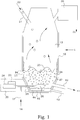
- Fig. 1 illustrates schematically an embodiment of an arrangement 1 for recovery of evaporable substances.
- the arrangement 1 comprises a furnace 10. Material 22 comprising evaporable metals and/or evaporable metal compounds is introduced through an inlet 21 into the furnace 10.
- a heating arrangement 20 is arranged for melting the material 22 introduced into the furnace 10 into a molten slag 24.
- the heating arrangement 20 comprises a plasma torch system 28 and a tuyere 29.
- the plasma torch 28 is thus arranged for supplying the energy necessary for melting the material 22, at least when it reaches the surface 25 of the slag bath.
- the plasma torch system 28 is designed to be capable of producing hot gas of a temperature of above 3000 °C, and most preferably above 4000 °C.
- the heating arrangement 20 may comprise other means turning the material 22 introduced into the furnace 10 into a molten slag 24.
- One example could be a pneumatic raw material feeding into the slag bath via a tuyere 29. Such heaters are then preferably combined with the effect of the plasma torch system 28 for achieving the melting.
- the material 22 could be molten before being entered into the furnace 10.
- the plasma torch system 28 is via a tuyere 29 submerged into the molten slag 24.
- the plasma torch system 28 is thereby also arranged for agitating the molten slag 24 by means of a submerged jet 26 of hot gas.
- the hot gas 27 creates bubbles in the molten slag 24, causing a violent stirring of the molten slag 24 on their way up to the surface 25 of the slag bath.
- the plasma torch is adapted to be operable to give the hot gas 27 an enthalpy of at least 200 MJ/kmol, and preferably of at least 300 MJ/kmol.
- the present embodiment further comprises a fume handling system 30.
- the fume handling system 30 is configured to collect the evaporable metals and/or evaporable metal compounds in the gas volume 12 that has been fuming off from the molten slag 24, either directly via the molten slag surface or via the bubbles of hot gas 27.
- the metals and/or metal compounds are handled in accordance with prior art methods for valuation of the final metals and/or metal compounds 31.
- the particular way in which the evaporable metals and/or evaporable metal compounds are handled is not crucial for the operation of the slag fuming arrangement as such and is therefore not further discussed.
- the present embodiment also comprises a slag outlet 40 allowing molten slag depleted in evaporable metals and/or evaporable metal compounds to be tapped off.
- the present embodiment of the arrangement 1 has a furnace that is arranged for performing a continuous process. In other words, the present embodiment is intended for a continuous operation, where the material 22 continuously or intermittently is introduced into the furnace 10. The material 22 melts when coming into contact with the hot gas in the gas volume 12 or when being contacted with the molten slag surface 25. During the agitation by the bubbles generated by the plasma torch gas jet 26, the molten slag becomes depleted in evaporable metals and/or evaporable metal compounds, that instead evaporates into the bubbles. The molten slag depleted in evaporable metals and/or evaporable metal compounds may continuously or intermittently be removed from the furnace 10 by the slag outlet 40.
- the furnace 10 can also be operated in a batch manner, where the material 22 first is entered into the furnace 10, then treated into a molten slag depleted in evaporable metals and/or evaporable metal compounds and finally removed from the furnace 10.
- the heating arrangement 20 comprises a controller 23 arranged for operating the heater arrangement 20 for keeping the molten slag 24 at a predetermined average temperature.
- the predetermined average temperature is preferably selected in dependence of the slag composition. Since most slags are composed to have a melting temperature of around 1100 °C, the predetermined average temperature should not exceed such value by too much.
- the controller 23 is preferably arranged for operating the heater arrangement 20 for keeping the molten slag 24 at an average temperature below 1200°C, and preferably below 1150°C.
- the controller 23 is preferably arranged for operating the heater arrangement 20 for keeping the molten slag 24 at an average temperature of less than 100°C above a melting temperature of the slag, and preferably less than 50°C above a melting temperature of the slag.
- the furnace 10 is equipped with a cooled wall 15, in order to create a freeze lining and be able to reduce the wear of the furnace wall.
- the predetermined average temperature of the slag is then also preferably selected in dependence of the performance of the cooled wall 15.
- the controller 23 is then arranged for balancing the predetermined average temperature of the slag to the reactor wall cooling to create a protective frozen slag layer 16 on the reactor wall 15.
- the arrangement 1 further comprises introduction means 17 arranged for adding carbon or hydrocarbon into the tuyeres 29 submerged into the slag bath transporting the hot gas from the plasma jet 26.
- introduction means 17 arranged for adding carbon or hydrocarbon into the tuyeres 29 submerged into the slag bath transporting the hot gas from the plasma jet 26.
- the oxygen potential is possible to be adjusted within the range of 10 -4 to 10 -14 atm. If the introduced reducing agents reduce the molten slag, such reactions are typically endothermic and further energy has typically to be provided to keep a constant temperature.
- the controller 23 is easily arranged for controlling the plasma torch to supply the necessary energy for reducing the molten slag.
- the introduction means 17 is arranged for adjusting an oxygen potential in the slag to be suitable for selectively reducing metal compounds in the slag into a molten metal phase.
- typical such metals that are possible to reduce from the slag are Cu, Ni, Ag, Au, Pt and Pd.
- the molten metal phase 44 is collected in the bottom of the furnace 10. The molten metal phase is removed, continuously or intermittently, via an outlet 42.
- the furnace 10 is for this purpose provided with a refractory 45 at the bottom.
- a matte phase can be obtained.
- the introduction means 17 is then arranged for adjusting an oxygen potential in the slag for preventing the sulphur from being oxidized.
- Metals may then be recovered in a molten matte phase. Examples of typical such metals that are possible to recover from the slag are Fe, Cu, Ni, Ag, Au, Pt and Pd.
- the molten matte phase is collected in the bottom of the furnace 10. The molten matte phase is removed, continuously or intermittently, via an outlet.
- both a metal phase and a matte phase can be obtained, by proper adjustment of the oxygen potential and the sulphur content.
- Au, Pt and Pd can be reduced into a metallic phase, whereas Cu and Ni form the matte phase.
- the matte phase typically appears on top of the metal phase, since it typically has a lower density than the metal phase and since the two phases are more or less unsolvable in each other.
- the matte phase and the metal phase can be extracted from the furnace by separate outlets or by a common outlet.
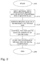
- Fig. 2 is a flow diagram of steps of an embodiment of a method for recovery of evaporable substances.
- the method begins in step 200.
- a material comprising evaporable metals and/or evaporable metal compounds is molten into a molten slag.
- the molten slag is in step 212 agitated by a submerged jet of hot gas.
- the energy for melting the material is supplied by the submerged jet of hot gas.
- the hot gas is controlled to have an enthalpy of at least 200 MJ/kmol, and preferably at least 300 MJ/kmol.
- the hot gas has a temperature upon entering the molten slag above 3000°C, and preferably above 4000°C.
- the molten slag At least for ordinary types of slag compositions, it is preferable to let control the molten slag to have an average temperature below 1200°C, and preferably below 1150°C. Since the slag melting temperature may differ with the actual slag composition, it is preferable to control the molten slag to an average temperature of less than 100°C above a melting temperature of the slag, and preferably less than 50°C above a melting temperature of the slag.
- One advantage of holding the molten slag at these temperatures is that a freeze lining is easier to maintain.
- At least a part of the evaporable metals and/or evaporable metal compounds is fumed off from the molten slag in step 216.
- a majority part of the evaporation takes place into the hot gas.
- the energy for fuming of the material is preferably supplied by the submerged jet of hot gas. The process ends in step 299.
- the process is illustrated as a single batch process.
- the method is operated as a continuous process.
- the different steps are preferably performed at least partially simultaneous and in a continuous or intermittent manner.
- the method further comprises adjustment of an oxygen potential of the hot gas by adding carbon or hydrocarbon into the hot gas.
- the oxygen potential can be adjusted within the range of 10 -4 to 10 -14 atm.
- the energy for reducing the molten slag is supplied by the submerged jet of hot gas.
- Test runs have been performed according to the above presented ideas.
- the slag was held at a temperature of 1100 °C and hot gas with an enthalpy of 280MJ/kmol was introduced submerged into the slag.
- 1000 kg of EAF dust, 100 kg of coke and 100 kg of sand was utilized in this test run as input material.
- the ingoing material was roasted Table 1.
- compositions of the components are given in Table 1. Note that the plasma gas and reducing agents are not included in the balance calculations. During the operation, a total of 701.5 kg of gas was extracted, from which 495.6 kg recovered products eventually was collected. In this particular experiment, the oxygen potential was held at a level appropriate for reducing the CuO into metallic copper, and Fe 2 O 3 into FeO, while Zn and Pb were extracted in the gas phase. Air was used as the plasma gas and the oxygen potential was controlled by introducing propane into the hot gas. The output of the experiment is shown in Table 2. As a conclusion, the level of ZnO was in the present test run reduced from 41.1 wt% in the EAF dust to 1.3 wt% in the final slag, which corresponds to an extraction degree of 98.4%. Such levels of Zn extraction has earlier only been achieved at slag temperatures over 1300 °C.
- the slag was again held at a temperature of 1100 °C and hot gas with an enthalpy of 280 MJ/kmol was introduced submerged into the slag.
- 1000 kg of EAF dust, 100 kg of coke and 100 kg of sand was utilized in this test run as input material.
- the compositions of the components are given in Table 3. S and SO 3 are present in the system. Note that the plasma gas and reducing agents are not included in the balance calculations.
- a total of 704.3 kg of gas was extracted, from which 485.5 kg recovered products, mainly ZnO, was collected.
- the oxygen potential was held at a level appropriate to prevent sulphur oxidation, therefore recovering the Cu and Ni, respectively, into copper-nickel matte, and Fe 2 O 3 into FeO and FeS, while Zn and Pb were extracted in the gas phase partially as metal vapours.
- Air was used as the plasma gas and the oxygen potential was controlled by introducing propane into the hot gas jet.
- the output of the experiment is shown in Table 4.
- the level of ZnO in the present test run was reduced from 40.3 wt% in the EAF dust to 1.3 wt% in the final slag, which corresponds to an extraction degree of 98.5%. Table 3.
Landscapes
- Engineering & Computer Science (AREA)
- Chemical & Material Sciences (AREA)
- Mechanical Engineering (AREA)
- Organic Chemistry (AREA)
- Manufacturing & Machinery (AREA)
- Materials Engineering (AREA)
- Metallurgy (AREA)
- General Life Sciences & Earth Sciences (AREA)
- Environmental & Geological Engineering (AREA)
- Life Sciences & Earth Sciences (AREA)
- Geology (AREA)
- General Engineering & Computer Science (AREA)
- Physics & Mathematics (AREA)
- Geochemistry & Mineralogy (AREA)
- Thermal Sciences (AREA)
- Chemical Kinetics & Catalysis (AREA)
- Plasma & Fusion (AREA)
- Manufacture And Refinement Of Metals (AREA)
- Plasma Technology (AREA)
Description
- The present invention relates in general to arrangements and methods for recovery of evaporable substances, and in particular to arrangements and methods for plasma induced fuming.
- During many years, recovery of metal values from metallurgical waste materials has been developed. Such recovery is beneficial for many reasons. One is that waste materials, e.g. EAF (Electric Arc Furnace) dust, and slag of different kinds often contains such high amounts of heavy metals that they are unsuitable for immediate deposition. Rest products comprising elements like Sn, Zn and Pb are preferably not returned in to the nature without any protective treatment. Furthermore, the value of these elements is also not negligible. By recovering these elements, the environment is saved at the same time as useful metals are obtained.
- It is since long known to use different types of fuming processes to recover evaporable substances both from primary sources, such as roasted Zn ores and from secondary sources, such as EAF dust, leaching residues and secondary slags. A typical simple slag fuming process produces a molten metallurgical slag. The slag is typically exposed to reducing agents and is heated to relative high temperatures. Vapours of volatile metals, such as e.g. zinc and lead, are transferred into the gas phase above the slag and the vapours are removed for further treatment to obtain the metallic components. One typical such example is found e.g. in the published patent application
GB 2 181 746 A US 5,942,023 . - In the US patent
US 4,571,260 , a method for recovering metal values from materials containing tin and/or zinc is disclosed. The method is basically a Kaldo process where a surface of a rotating slag bath is exposed for oxygen and fuel. Flux and coke are added to achieve a suitable viscosity and appropriate agitation. - A disadvantage with most early slag fuming arrangements is that the efficiency in removing the volatile metals was not always the best. Relatively high contents of hazardous substances were remaining in the final slag.
- Today literature and operational practice often mention and apply high temperature treatment of volatile containing materials. The high temperatures are necessary to ensure high fuming rates and high yields. As an example Zn fuming from fayalite slags can be used. Here the slag is superheated above its normal melting point of 1100 °C. This superheating of the slag results in excellent fuming, however, it results also in high refractory wear and higher energy consumption of the process.
- Water cooled vessels are typically used to overcome the short lifecycle of the refractory, however, at a high cost of heat loss that comes with it. Therefore the smelters typically have to compromise between high wear, low fuming rates and high heat losses.
- The above mentioned issues with high refractory wear and high energy cost were addressed in published international patent application
WO 2005/031014 . There, high Zn fuming rates without any need to superheat the slag are described. According to that approach, the melting point of the slag is increased to 1300 °C by adding suitable fluxes. By doing so, there is limited or no need for the slag to be superheated to obtain high fuming rates. The reason is that the desired temperature for high fuming rates is typically around 1300 °C, and since the melting point of the slag is around 1300 °C, superheating is typically not necessary. Such a slag is said to build a protective freeze lining on top of the refractory on water cooled walls and this approach therefore minimizing the wear of the lining. The fuming process according toWO 2005/031014 however comes at the cost of energy needed to heat all of the slag volume in the reactor up to 1300 °C, and at the cost for fluxes that need to be added to increase the melting point of the slag. Similar methods are disclosed also in the published US patent applicationUS 2010/0050814 A1 and the published international patent applicationWO 2008/052661 A1 . - Another approach is disclosed in the published US patent
US 4,252,563 . There it is described a continuous of slag fuming process where the slag is fumed in two consecutive slag treatment zones. In the first zone, the slag is subjected to heat treatment for fuming off volatile, preferably sulphide bound, constituents. In the subsequent second furnace zone, the slag is subjected to reduction treatment, where oxides are reduced to their elementary form and fumed off. If the slag is subjected to further separation after the fuming process, it can be subjected to a further 3rd zone for copper recovery. However this 3rd zone has again to be heated since the temperature of the slag after zone 2 drops considerably. The slag temperature is adjusted in the first zone so that the reduction and fuming treatment in the second zone can be carried out essentially without any further heating of the slag. Preheated air and pulverized coal is used for heating the slag, giving the process a need for a robust off-gas system. Utilization of coal as fuel gives the process limitations for energy input and oxygen potential. At relatively strong reduction conditions, huge amounts of coal have to be supplied to cover the energy demand for heating and reduction. This gives rise to very high amounts of exhausted greenhouse gases. - The use of submerged plasma torches generating a gas agitating the slag bath and for feeding of reducing agents is known, e.g. as disclosed in the published US patent application
US 2010/0050814 . - Despite the development in this technical area, there are still remaining problems. In particular, by solving the earlier problems with lining wear and fuming rate, the costs for fluxes, heating and cooling is increased, as well as, in some cases, the high emissions of carbon oxides.
- A general object of the present invention is to improve recovery of evaporable substances. A particular object of the present invention is to reduce the use of slag formers, to reduce the requested amount of supplied energy and still ensure a low wear on the refractories in the reactor.
- The above objects are achieved by a method according to the enclosed independent claim. Preferred embodiments are specified by the dependent claims. In general, in a first aspect, a method for recovery of evaporable substances comprises melting of a material comprising evaporable metals and/or evaporable metal compounds into a molten slag. The molten slag is agitated by a submerged jet of hot gas. The hot gas is controlled to have an enthalpy of at least 200 MJ/kmol, and preferably at least 300 MJ/kmol. At least a part of the evaporable metals and/or evaporable metal compounds are fumed off from the molten slag.
- One advantage with the present invention is that the required amount of energy for the plasma induced fuming is reduced, while keeping the extraction efficiency on a comparable level. Another advantage is that the need of slag formers is reduced and thereby also the final amount of slag that has to be disposed. Furthermore valuable compounds can be collected in a matte and/or metal phase. Other advantages are described in connection with the different embodiments in the detailed description section.
- The invention, together with further objects and advantages thereof, may best be understood by making reference to the following description taken together with the accompanying drawings, in which:
-
FIG. 1 is a schematic illustration of an arrangement for recovery of evaporable substances; and -
FIG. 2 is a flow diagram of steps of an embodiment of a method for recovery of evaporable substances. - Throughout the drawings, the same reference numbers are used for similar or corresponding elements.
- The invention stated in this patent describes recovery of volatile non-ferrous metals from secondary and primary materials.
- The use of submerged plasma torches generating a gas agitating the slag bath and for feeding of reducing agents is known since long. The introduced gas gives a thorough agitation of the melt at the same time as heat is added to the melt. Furthermore, additional substances can be added in the plasma gas, e.g. reducing agents.
- An advantage with the use of a submerged plasma torch is that the amount of heat added to the melt is independent of the amount of added reducing agents. In systems, where different carbon compounds are utilized for creating the heat, the oxygen potential and the heat generation will be intimately connected. By use of the plasma torch, virtually any oxygen potential can be combined with any amount of heat generation.
- In prior art slag fuming methods, development efforts have been driven by evaluating equilibrium or quasi-equilibrium homogeneous conditions in the slag bath. When the average temperature of the slag is high enough, the slag fuming rate becomes high. Volatile elements leave the slag bath by the upper slag bath surface and enter into the gas phase above the slag.
- One idea of the present approach is to instead to utilize dynamic effects and inhomogeneous conditions. If a submerged plasma torch is used, the agitation and the supply of gas into the slag bath cause conditions that are far from homogeneous or equilibrium-like. Such local conditions could be utilized to further improve the fuming properties.
- It has also surprisingly been found that by using a submerged plasma torch introducing gas with an extremely high enthalpy, high slag fuming rates are achievable far below the earlier indicated requested average slag temperatures. In other words, even if the average slag temperature is far below the prior art high fuming rate temperatures, volatile elements are efficiently extracted from the slag. This indicates that a completely new fuming mechanism must have been activated.
- The gas bubbles with the extreme high enthalpy have surprisingly been seen to extract evaporable substances at very high rate. The life time of a bubble is very short, nevertheless, large amounts of volatile elements anyway have managed to leave the slag to enter into the bubbles. It was found that the boosting effect of the plasma gas became noticeable when the gas entering the slag has an enthalpy of
minimum 200 MJ/kmol. Preferably, the gas entering the slag has an enthalpy of minimum 300 MJ/kmol. Enthalpies up to 369 MJ/kmol have been successfully tested. The temperature of the interface between the liquid slag and the gas bubble then becomes much higher than the average slag temperature is. Because of this hot interface, the mass transfer of the elements that are to be fumed is accelerated, giving high fuming rates of metallic and/or oxidic vapours. The high mass transfer of metallic and/or oxidic vapour may furthermore be enhanced by controlling the gas jet from the plasma system. The gas jet can thereby be adapted to give the most suitable oxygen potential and zero partial pressure of the elements/compounds which are to be fumed. - Since the average slag temperature no longer is the crucial critical parameter, the average slag temperature can be selected according to other preferences. For instance, the average slag temperature can be adapted to create a protective freeze lining on the water cooled walls. The average slag temperature can thereby be controlled in dependence of the slag composition to assume a value appropriate for freeze lining. The present approach thus opens an alternative process for high fuming rates at average slag temperatures, even as low as 1100 °C. If the slag composition is appropriate, a protective freeze lining will be created on the water cooled walls. Furthermore, no refractory is needed in such a setting, since such a slag is freezing promptly on the surface of the steel walls. The slag is heated to the temperatures needed to create freeze lining by controlling the gas flow of the submerged plasma jet having the mentioned high enthalpies.
- As mentioned further above, the plasma jet is also possible to utilize for ensuring strongly agitated slag and for providing ability to work at any oxygen potential at a same energy input.
-
Fig. 1 illustrates schematically an embodiment of anarrangement 1 for recovery of evaporable substances. Thearrangement 1 comprises afurnace 10.Material 22 comprising evaporable metals and/or evaporable metal compounds is introduced through aninlet 21 into thefurnace 10. Aheating arrangement 20 is arranged for melting thematerial 22 introduced into thefurnace 10 into amolten slag 24. In the present embodiment, theheating arrangement 20 comprises aplasma torch system 28 and atuyere 29. Theplasma torch 28 is thus arranged for supplying the energy necessary for melting thematerial 22, at least when it reaches thesurface 25 of the slag bath. Preferably, theplasma torch system 28 is designed to be capable of producing hot gas of a temperature of above 3000 °C, and most preferably above 4000 °C. - In alternative embodiments, the
heating arrangement 20 may comprise other means turning thematerial 22 introduced into thefurnace 10 into amolten slag 24. One example could be a pneumatic raw material feeding into the slag bath via atuyere 29. Such heaters are then preferably combined with the effect of theplasma torch system 28 for achieving the melting. Further alternatively, thematerial 22 could be molten before being entered into thefurnace 10. - In the embodiment of
Fig. 1 , theplasma torch system 28 is via atuyere 29 submerged into themolten slag 24. Theplasma torch system 28 is thereby also arranged for agitating themolten slag 24 by means of a submergedjet 26 of hot gas. Thehot gas 27 creates bubbles in themolten slag 24, causing a violent stirring of themolten slag 24 on their way up to thesurface 25 of the slag bath. The plasma torch is adapted to be operable to give thehot gas 27 an enthalpy of at least 200 MJ/kmol, and preferably of at least 300 MJ/kmol. By this high enthalpy evaporable metals and/or evaporable metal compounds are fumed off from themolten slag 24 into the bubbles ofhot gas 27. A smaller amount of evaporable metals and/or evaporable metal compounds are also fumed off directly into agas volume 12 above themolten slag surface 25. The bubbles ofhot gas 27 are rapidly transported to themolten slag surface 25, and there releasing the content in thehot gas 27 into thegas volume 12. - The present embodiment further comprises a
fume handling system 30. Thefume handling system 30 is configured to collect the evaporable metals and/or evaporable metal compounds in thegas volume 12 that has been fuming off from themolten slag 24, either directly via the molten slag surface or via the bubbles ofhot gas 27. The metals and/or metal compounds are handled in accordance with prior art methods for valuation of the final metals and/or metal compounds 31. The particular way in which the evaporable metals and/or evaporable metal compounds are handled is not crucial for the operation of the slag fuming arrangement as such and is therefore not further discussed. - The present embodiment also comprises a
slag outlet 40 allowing molten slag depleted in evaporable metals and/or evaporable metal compounds to be tapped off. The present embodiment of thearrangement 1 has a furnace that is arranged for performing a continuous process. In other words, the present embodiment is intended for a continuous operation, where thematerial 22 continuously or intermittently is introduced into thefurnace 10. The material 22 melts when coming into contact with the hot gas in thegas volume 12 or when being contacted with themolten slag surface 25. During the agitation by the bubbles generated by the plasmatorch gas jet 26, the molten slag becomes depleted in evaporable metals and/or evaporable metal compounds, that instead evaporates into the bubbles. The molten slag depleted in evaporable metals and/or evaporable metal compounds may continuously or intermittently be removed from thefurnace 10 by theslag outlet 40. - In an alternative embodiment, the
furnace 10 can also be operated in a batch manner, where the material 22 first is entered into thefurnace 10, then treated into a molten slag depleted in evaporable metals and/or evaporable metal compounds and finally removed from thefurnace 10. - In one preferred embodiment, the
heating arrangement 20 comprises acontroller 23 arranged for operating theheater arrangement 20 for keeping themolten slag 24 at a predetermined average temperature. The predetermined average temperature is preferably selected in dependence of the slag composition. Since most slags are composed to have a melting temperature of around 1100 °C, the predetermined average temperature should not exceed such value by too much. For systems having standard slag compositions, thecontroller 23 is preferably arranged for operating theheater arrangement 20 for keeping themolten slag 24 at an average temperature below 1200°C, and preferably below 1150°C. For other systems, having other slag melting temperatures, thecontroller 23 is preferably arranged for operating theheater arrangement 20 for keeping themolten slag 24 at an average temperature of less than 100°C above a melting temperature of the slag, and preferably less than 50°C above a melting temperature of the slag. - In a preferred embodiment, the
furnace 10 is equipped with a cooledwall 15, in order to create a freeze lining and be able to reduce the wear of the furnace wall. The predetermined average temperature of the slag is then also preferably selected in dependence of the performance of the cooledwall 15. Thecontroller 23 is then arranged for balancing the predetermined average temperature of the slag to the reactor wall cooling to create a protectivefrozen slag layer 16 on thereactor wall 15. - As briefly mentioned above, one of the advantages in using a plasma torch for supplying the energy into a slag bath is that one easily can obtain control of an amount of introduced reduction agents without putting constraints on the total supplied power. In one preferred embodiment, the
arrangement 1 further comprises introduction means 17 arranged for adding carbon or hydrocarbon into thetuyeres 29 submerged into the slag bath transporting the hot gas from theplasma jet 26. This enables adjusting of an oxygen potential of thehot gas 27. The oxygen potential is possible to be adjusted within the range of 10-4 to 10-14 atm. If the introduced reducing agents reduce the molten slag, such reactions are typically endothermic and further energy has typically to be provided to keep a constant temperature. When using a plasma torch, thecontroller 23 is easily arranged for controlling the plasma torch to supply the necessary energy for reducing the molten slag. - In combination with the recovery of the volatile metals, also other metals can be extracted from the material 22 introduced into the
furnace 10. In one embodiment, the introduction means 17 is arranged for adjusting an oxygen potential in the slag to be suitable for selectively reducing metal compounds in the slag into a molten metal phase. Examples of typical such metals that are possible to reduce from the slag are Cu, Ni, Ag, Au, Pt and Pd. Themolten metal phase 44 is collected in the bottom of thefurnace 10. The molten metal phase is removed, continuously or intermittently, via anoutlet 42. Thefurnace 10 is for this purpose provided with a refractory 45 at the bottom. - In another embodiment, where the
material 22 introduced into thefurnace 10 and thereby also the slag comprises sulphur or sulphur compounds, also a matte phase can be obtained. The introduction means 17 is then arranged for adjusting an oxygen potential in the slag for preventing the sulphur from being oxidized. Metals may then be recovered in a molten matte phase. Examples of typical such metals that are possible to recover from the slag are Fe, Cu, Ni, Ag, Au, Pt and Pd. The molten matte phase is collected in the bottom of thefurnace 10. The molten matte phase is removed, continuously or intermittently, via an outlet. - In yet another embodiment, both a metal phase and a matte phase can be obtained, by proper adjustment of the oxygen potential and the sulphur content. As a non-limiting example, Au, Pt and Pd can be reduced into a metallic phase, whereas Cu and Ni form the matte phase. The matte phase typically appears on top of the metal phase, since it typically has a lower density than the metal phase and since the two phases are more or less unsolvable in each other. The matte phase and the metal phase can be extracted from the furnace by separate outlets or by a common outlet.
-
Fig. 2 is a flow diagram of steps of an embodiment of a method for recovery of evaporable substances. The method begins instep 200. Instep 210, a material comprising evaporable metals and/or evaporable metal compounds is molten into a molten slag. The molten slag is instep 212 agitated by a submerged jet of hot gas. Preferably, the energy for melting the material is supplied by the submerged jet of hot gas. Instep 214, the hot gas is controlled to have an enthalpy of at least 200 MJ/kmol, and preferably at least 300 MJ/kmol. Preferably, the hot gas has a temperature upon entering the molten slag above 3000°C, and preferably above 4000°C. At least for ordinary types of slag compositions, it is preferable to let control the molten slag to have an average temperature below 1200°C, and preferably below 1150°C. Since the slag melting temperature may differ with the actual slag composition, it is preferable to control the molten slag to an average temperature of less than 100°C above a melting temperature of the slag, and preferably less than 50°C above a melting temperature of the slag. One advantage of holding the molten slag at these temperatures is that a freeze lining is easier to maintain. At least a part of the evaporable metals and/or evaporable metal compounds is fumed off from the molten slag instep 216. Preferably, a majority part of the evaporation takes place into the hot gas. The energy for fuming of the material is preferably supplied by the submerged jet of hot gas. The process ends instep 299. - In
Fig. 2 , the process is illustrated as a single batch process. However, in a preferred embodiment, the method is operated as a continuous process. In other words, the different steps are preferably performed at least partially simultaneous and in a continuous or intermittent manner. - Preferably, the method further comprises adjustment of an oxygen potential of the hot gas by adding carbon or hydrocarbon into the hot gas. The oxygen potential can be adjusted within the range of 10-4 to 10-14 atm. The energy for reducing the molten slag is supplied by the submerged jet of hot gas.
- Test runs have been performed according to the above presented ideas. In one particular experiment the slag was held at a temperature of 1100 °C and hot gas with an enthalpy of 280MJ/kmol was introduced submerged into the slag. 1000 kg of EAF dust, 100 kg of coke and 100 kg of sand was utilized in this test run as input material. The ingoing material was roasted
Table 1. Input quantities Material EAF dust Coke Sand Amount kg: 1000 100 100 Compound wt% wt% wt% SiO2 4.0 85.7 MnO 2.0 P2O5 0.4 Cr2O3 0.3 NiO 1.0 MgO 1.9 CuO 0.4 Cu 0.0 TiO2 0.1 Al2O3 0.9 9.8 FeO 0.0 2.0 Fe2O3 24.7 CaO 4.8 2.5 Na2O 1.1 K2O 0.3 ZnO 41.1 Zn 0.0 PbO 4.7 Pb 0.0 C 2.2 99.6 S 0.0 0.4 H2O 5.1 0.0 KCl 2.9 NaCl 1.5 SO3 0.0 O 0.5 SUM 100.0 100.0 100.0 Table 2. Output quantities Material Metal Slag Gas Recovered product Amount kg: 6.9 491.6 701.5 495.6 Compound wt% wt% wt% wt% SiO2 25.5 I MnO 4.0 P2O5 0.7 Cr2O3 0.7 NiO 0.8 Ni 68.7 MgO 3.9 CuO 0.2 Cu 31.3 TiO2 0.1 Al2O3 3.9 FeO 45.6 Fe2O3 0.0 CaO 10.2 Na2O 2.3 K2O 0.7 ZnO 1.3 81.6 Zn 46.3 PbO 0.0 9.5 Pb 6.2 C 17.4 H2O (vapour) 3.7 KCl 4.1 5.8 NaCl 2.2 3.0 O 19.6 SO2 0.1 H 0.4 SUM 100 100 100 100 - In another particular experiment the slag was again held at a temperature of 1100 °C and hot gas with an enthalpy of 280 MJ/kmol was introduced submerged into the slag. 1000 kg of EAF dust, 100 kg of coke and 100 kg of sand was utilized in this test run as input material. The compositions of the components are given in Table 3. S and SO3 are present in the system. Note that the plasma gas and reducing agents are not included in the balance calculations. During the operation, a total of 704.3 kg of gas was extracted, from which 485.5 kg recovered products, mainly ZnO, was collected. In this particular experiment, the oxygen potential was held at a level appropriate to prevent sulphur oxidation, therefore recovering the Cu and Ni, respectively, into copper-nickel matte, and Fe2O3 into FeO and FeS, while Zn and Pb were extracted in the gas phase partially as metal vapours. Air was used as the plasma gas and the oxygen potential was controlled by introducing propane into the hot gas jet. The output of the experiment is shown in Table 4. As a conclusion, the level of ZnO in the present test run was reduced from 40.3 wt% in the EAF dust to 1.3 wt% in the final slag, which corresponds to an extraction degree of 98.5%.
Table 3. Input quantities Material EAF dust Coke Sand Amount kg: 1000 100 100 Compound wt% wt% wt% SiO2 3.9 85.7 MnO 1.9 P2O5 0.3 Cr2O3 0.3 NiO 1.0 MgO 1.9 CuO 0.4 Cu 0.0 TiO2 0.1 Al2O3 0.9 9.8 FeO 0.0 2.0 Fe2O3 24.2 CaO 4.7 2.5 Na2O 1.1 K2O 0.3 ZnO 40.3 Zn 0.0 PbO 4.6 Pb 0.0 C 2.2 99.6 s 0.6 0.4 H2O 5.0 0.0 KCl 2.8 NaCl 1.5 SO3 1.5 O 0.5 SUM 100.0 100.0 100.0 Table 4. Output quantities Material Matte Slag Gas Recovered product Amount kg: 17.1 478.6 704.3 485.5 Compound wt% wt% wt% wt% SiO2 26.0 MnO 4.0 P2O5 0.7 Cr2O3 0.7 NiO 0.8 NiS 42.2 MgO 3.9 CuO 0.2 Cu2S 15.3 TiO2 0.1 Al2O3 4.0 FeO 44.7 FeS 42.5 CaO 10.3 Na2O 2.3 K2O 0.7 ZnO 1.3 81.6 ZnS 0.0 Zn 45.2 PbO 0.0 9.5 PbS 0.0 Pb 6.1 C 17.3 H2O (vapour) 3.6 KCl 4.0 5.8 NaCl 2.1 3.0 O 19.8 SO2 1.5 S 0.2 H 0.4 SUM 100 100 100 100 - Minor amounts of platinum group metals and noble metals were also present in the experiments presented above. It was found that at least 98% of the Au, Pt and Pd were recovered into the metal or matte phase. The Ag was collected to 50-60% in the metal or matte phase, while 40-50% ended up in the filter cake.
- The embodiments described above are to be understood as a few illustrative examples of the present invention. It will be understood by those skilled in the art that various modifications, combinations and changes may be made to the embodiments without departing from the scope of the present invention. In particular, different part solutions in the different embodiments can be combined in other configurations, where technically possible. The scope of the present invention is, however, defined by the appended claims.
Claims (17)
- A method for recovery of evaporable substances, comprising the steps of:melting (210) a material comprising at least one of evaporable metals and evaporable metal compounds into a molten slag;agitating (212) said molten slag by a submerged jet of hot gas from a submerged plasma torch; andfuming off (216) at least a part of said at least one of evaporable metals and evaporable metal compounds from said molten slag, characterized by the further step ofcontrolling (214) said hot gas to have an enthalpy of at least 200 MJ/kmol.
- The method according to claim 1, characterized in that said step of controlling (214) said hot gas comprises controlling (214) said hot gas to have an enthalpy of at least 300 MJ/kmol.
- The method according to claim 1 or 2, characterized in that said step of fuming off (216) at least a part of said at least one of evaporable metals and evaporable metal compounds from said molten slag comprises evaporation of said at least one of evaporable metals and evaporable metal compounds are fumed off into said hot gas.
- The method according to any of the claims 1 to 3, characterized in that said molten slag has an average temperature of less than 100°C above a melting temperature of said slag.
- The method according to any of the claims 1 to 3, characterized in that said molten slag has an average temperature of less than 50°C above said melting temperature of said slag.
- The method according to any of the claims 1 to 5, characterized in that said molten slag has an average temperature below 1200°C.
- The method according to any of the claims 1 to 5, characterized in that said molten slag has an average temperature below 1150°C.
- The method according to any of the claims 1 to 7, characterized in that said hot gas has a temperature upon entering said molten slag above 3000°C.
- The method according to any of the claims 1 to 7, characterized in that said hot gas has a temperature upon entering said molten slag above 4000°C.
- The method according to any of the claims 1 to 9, characterized in that the energy for melting and/or fuming of said material is supplied by said submerged jet of hot gas.
- The method according to any of the claims 1 to 10, characterized by adjusting an oxygen potential of said hot gas by adding carbon or hydrocarbon into said hot gas.
- The method according to any of the claims 1 to 11, characterized by adjusting an oxygen potential in said slag by adding solid carbon and/or hydrocarbon into said slag.
- The method according to claim 11 or 12, characterized in that said oxygen potential is adjusted within the range of 10-4 to 10-14 atm.
- The method according to any of the claims 11 to 13, characterized in that said step of adjusting an oxygen potential in said slag comprises adjusting an oxygen potential in said slag for reducing metal compounds in said slag into a molten metal phase;
and by the further step of removing said molten metal phase. - The method according to any of the claims 11 to 14, characterized in that
said slag comprises sulphur or sulphur compounds;
said step of adjusting an oxygen potential in said slag comprises adjusting an oxygen potential in said slag for preventing sulphur from being oxidized, collecting metal compounds in said slag into a molten matte phase; and by the further step of removing said molten matte phase. - The method according to any of the claims 1 to 15, characterized in that the energy for reducing said molten slag is supplied by said submerged jet of hot gas.
- The method according to any of the claims 1 to 16, characterized in that the method is a continuous process.
Applications Claiming Priority (2)
| Application Number | Priority Date | Filing Date | Title |
|---|---|---|---|
| SE1251067A SE537235C2 (en) | 2012-09-21 | 2012-09-21 | Process and arrangement for the recovery of vaporizable substances from a slag by means of plasma induced vaporization |
| PCT/SE2013/051014 WO2014046593A1 (en) | 2012-09-21 | 2013-08-29 | Plasma induced fuming |
Publications (3)
| Publication Number | Publication Date |
|---|---|
| EP2898106A1 EP2898106A1 (en) | 2015-07-29 |
| EP2898106A4 EP2898106A4 (en) | 2016-06-15 |
| EP2898106B1 true EP2898106B1 (en) | 2019-02-20 |
Family
ID=50342516
Family Applications (1)
| Application Number | Title | Priority Date | Filing Date |
|---|---|---|---|
| EP13838833.5A Active EP2898106B1 (en) | 2012-09-21 | 2013-08-29 | Plasma induced fuming |
Country Status (7)
| Country | Link |
|---|---|
| US (1) | US10006100B2 (en) |
| EP (1) | EP2898106B1 (en) |
| JP (1) | JP6378683B2 (en) |
| KR (1) | KR102176989B1 (en) |
| ES (1) | ES2726818T3 (en) |
| SE (1) | SE537235C2 (en) |
| WO (1) | WO2014046593A1 (en) |
Families Citing this family (9)
| Publication number | Priority date | Publication date | Assignee | Title |
|---|---|---|---|---|
| FR3020663B1 (en) * | 2014-04-30 | 2016-05-27 | Commissariat Energie Atomique | ARRANGEMENT OF THE OUTLET PIPE OF AN IMMERSION PLASMA TORCH DEDICATED TO THE TREATMENT OF WASTE |
| MA40377B1 (en) * | 2014-11-19 | 2018-12-31 | Umicore Nv | Plasma and oxygen furnace |
| MX2017012477A (en) | 2015-04-03 | 2018-06-18 | Metallo Belgium | IMPROVED ESCORIES FROM THE PRODUCTION OF NON-FERROUS METALS. |
| WO2016164636A1 (en) | 2015-04-09 | 2016-10-13 | The Regents Of The University Of California | Engineered bacteria for production and release of therapeutics |
| FI127188B (en) * | 2015-04-10 | 2018-01-15 | Outotec Finland Oy | PROCEDURES AND ARRANGEMENTS FOR USING A METALLURGICAL OVEN AND COMPUTER PROGRAM PRODUCT |
| KR101617167B1 (en) * | 2015-08-12 | 2016-05-03 | 한국수력원자력 주식회사 | Plasma melter having side discharge gates |
| CA3102955A1 (en) | 2018-06-08 | 2019-12-12 | The Regents Of The University Of California | Multistrain population control systems and methods |
| KR102832980B1 (en) * | 2019-11-22 | 2025-07-15 | 오루비스 비어스 | Improved plasma induced combustion |
| US12594307B2 (en) | 2019-12-13 | 2026-04-07 | The Regents Of The University Of California | Compositions and methods of using inducible signaling for tunable dynamics in microbial communities |
Family Cites Families (22)
| Publication number | Priority date | Publication date | Assignee | Title |
|---|---|---|---|---|
| BE653612A (en) * | 1963-09-30 | |||
| US3891428A (en) * | 1966-03-24 | 1975-06-24 | Za Zvetni Metali Dimiter Blago | Method for treating non-ferrous metal slag |
| US3892559A (en) * | 1969-09-18 | 1975-07-01 | Bechtel Int Corp | Submerged smelting |
| SE396967B (en) | 1975-08-25 | 1977-10-10 | Boliden Ab | PROCEDURE FOR CONTINUOUS SMOKING TREATMENT OF METALLURGIC SLAGS |
| DE3029741A1 (en) * | 1980-08-06 | 1982-04-01 | Metallgesellschaft Ag, 6000 Frankfurt | METHOD FOR CONTINUOUSLY DIRECT MELTING OF METAL LEAD FROM SULFURED LEAD MATERIALS |
| SE500352C2 (en) * | 1982-04-07 | 1994-06-06 | Nordic Distributor Supply Ab | Ways of extracting metals from liquid slag |
| AU565803B2 (en) | 1984-02-07 | 1987-10-01 | Boliden Aktiebolag | Refining of lead by recovery of materials containing tin or zinc |
| US4655437A (en) * | 1985-05-03 | 1987-04-07 | Huron Valley Steel Corp. | Apparatus for simultaneously separating volatile and non-volatile metals |
| GB8523397D0 (en) | 1985-09-21 | 1985-10-23 | Commw Smelting Ltd | Recovery of meal values from slags |
| WO1988001654A1 (en) * | 1986-08-27 | 1988-03-10 | Commonwealth Scientific And Industrial Research Or | Process for the treatment of lead-zinc ores, concentrates or residues |
| WO1991008317A1 (en) * | 1989-12-05 | 1991-06-13 | Mount Isa Mines Limited | Zinc smelting |
| DE69125021T2 (en) * | 1990-11-14 | 1997-06-12 | Minproc Technology Pty Ltd | DISTILLATION BY DIRECT SULFIDISATION OF ZINC |
| US5203908A (en) | 1992-03-02 | 1993-04-20 | Plasma Processing Corporation | Process for recovery of free aluminum from aluminum dross or aluminum scrap using plasma energy at high enthalpy |
| AUPM657794A0 (en) * | 1994-06-30 | 1994-07-21 | Commonwealth Scientific And Industrial Research Organisation | Copper converting |
| GB9502222D0 (en) * | 1995-02-04 | 1995-03-22 | Imp Smelting Processes | Smelting process |
| US5942023A (en) | 1997-02-12 | 1999-08-24 | Exide Corporation | Process for recovering metals from electric arc furnace (EAF) dust |
| AT406474B (en) * | 1998-03-17 | 2000-05-25 | Holderbank Financ Glarus | METHOD FOR CONVERTING SLAG FROM NON-IRON METALLURGY |
| AUPP554098A0 (en) * | 1998-08-28 | 1998-09-17 | Technological Resources Pty Limited | A process and an apparatus for producing metals and metal alloys |
| DE602004007154T2 (en) * | 2003-09-29 | 2008-02-21 | Umicore | METHOD AND DEVICE FOR OBTAINING NON-STEEL METALS FROM ZINC RESIDUES |
| JP5183638B2 (en) * | 2006-11-02 | 2013-04-17 | ユミコア ソシエテ アノニム | Recovery of non-ferrous metals from zinc and lead industry byproducts using electrothermal smelting in submerged plasma |
| KR101383521B1 (en) * | 2006-11-02 | 2014-04-08 | 유미코르 | Recovery of non-ferrous metals from by-products of the zinc and lead industry using electric smelting with submerged plasma |
| EP2053137A1 (en) * | 2007-10-19 | 2009-04-29 | Paul Wurth S.A. | Recovery of waste containing copper and other valuable metals |
-
2012
- 2012-09-21 SE SE1251067A patent/SE537235C2/en unknown
-
2013
- 2013-08-29 KR KR1020157010317A patent/KR102176989B1/en active Active
- 2013-08-29 US US14/429,561 patent/US10006100B2/en active Active
- 2013-08-29 WO PCT/SE2013/051014 patent/WO2014046593A1/en not_active Ceased
- 2013-08-29 ES ES13838833T patent/ES2726818T3/en active Active
- 2013-08-29 EP EP13838833.5A patent/EP2898106B1/en active Active
- 2013-08-29 JP JP2015533013A patent/JP6378683B2/en active Active
Non-Patent Citations (1)
| Title |
|---|
| None * |
Also Published As
| Publication number | Publication date |
|---|---|
| KR102176989B1 (en) | 2020-11-10 |
| JP6378683B2 (en) | 2018-08-22 |
| EP2898106A1 (en) | 2015-07-29 |
| US10006100B2 (en) | 2018-06-26 |
| SE1251067A1 (en) | 2014-03-22 |
| US20150232961A1 (en) | 2015-08-20 |
| WO2014046593A1 (en) | 2014-03-27 |
| JP2015535883A (en) | 2015-12-17 |
| ES2726818T3 (en) | 2019-10-09 |
| SE537235C2 (en) | 2015-03-10 |
| KR20150076168A (en) | 2015-07-06 |
| EP2898106A4 (en) | 2016-06-15 |
Similar Documents
| Publication | Publication Date | Title |
|---|---|---|
| US10006100B2 (en) | Plasma induced fuming | |
| US9611520B2 (en) | Base metal recovery | |
| KR102412765B1 (en) | Lithium-enriched metallurgical slag | |
| US8088192B2 (en) | Recovery of residues containing copper and other valuable metals | |
| US8110019B2 (en) | Modified induction furnace and process for removing zinc-containing metallurgical waste, with recovery of the metals therefrom | |
| TWI874497B (en) | Improved copper smelting process | |
| JP5183638B2 (en) | Recovery of non-ferrous metals from zinc and lead industry byproducts using electrothermal smelting in submerged plasma | |
| PL135369B1 (en) | Method of reclaiming volatile metals form materials containing metal oxides | |
| Errington et al. | The ISA-YMG lead smelting process | |
| MXPA04011345A (en) | Continuous steelmaking process in an eaf and plant slag composition for use therein. | |
| US20160186291A1 (en) | Continuous Ore Process and Apparatus Using Plasma | |
| ES3026670T3 (en) | Process for the smelting of a metalliferous feedstock material | |
| JP2023503236A (en) | Improved plasma-induced fuming furnace | |
| Verscheure et al. | Investigation of zinc fuming processes for the treatment of zinc-containing residues | |
| JP5614056B2 (en) | Method of operating copper smelting furnace and copper smelting furnace | |
| JP2009167469A (en) | Processing method for copper-containing dross | |
| Errington, WJ*, Edwards, JS* & Hawkins | Isamelt technology-current status and future development | |
| Abdellatif | Review of the development work on the Mintek Thermal Magnesium Process (MTMP) | |
| Moosavi-Khoonsari et al. | Technology selection for slag zinc fuming process | |
| WO2020149777A1 (en) | Treatment of ferric iron based material comprising zinc and sulphur | |
| EA053300B1 (en) | METHOD OF OXIDATIVE PRE-MELTING AND MELTING OF AGGLOMERATE OF METAL-CONTAINING RAW MATERIAL | |
| Barcza et al. | " University of Missouri-Rolla, MO 65401-0249, USA+ The Doe Run Company, 881 Main Street, Herculaneum, MO 63048, USA | |
| MXPA97008321A (en) | Process to reduce powders in electric steel structures and installation for implement |
Legal Events
| Date | Code | Title | Description |
|---|---|---|---|
| PUAI | Public reference made under article 153(3) epc to a published international application that has entered the european phase |
Free format text: ORIGINAL CODE: 0009012 |
|
| 17P | Request for examination filed |
Effective date: 20150421 |
|
| AK | Designated contracting states |
Kind code of ref document: A1 Designated state(s): AL AT BE BG CH CY CZ DE DK EE ES FI FR GB GR HR HU IE IS IT LI LT LU LV MC MK MT NL NO PL PT RO RS SE SI SK SM TR |
|
| AX | Request for extension of the european patent |
Extension state: BA ME |
|
| DAX | Request for extension of the european patent (deleted) | ||
| RA4 | Supplementary search report drawn up and despatched (corrected) |
Effective date: 20160512 |
|
| RIC1 | Information provided on ipc code assigned before grant |
Ipc: C22B 19/30 20060101ALI20160506BHEP Ipc: C22B 19/12 20060101ALI20160506BHEP Ipc: C22B 9/22 20060101ALI20160506BHEP Ipc: F27B 1/16 20060101ALI20160506BHEP Ipc: C22B 5/16 20060101AFI20160506BHEP |
|
| STAA | Information on the status of an ep patent application or granted ep patent |
Free format text: STATUS: EXAMINATION IS IN PROGRESS |
|
| 17Q | First examination report despatched |
Effective date: 20170713 |
|
| GRAP | Despatch of communication of intention to grant a patent |
Free format text: ORIGINAL CODE: EPIDOSNIGR1 |
|
| STAA | Information on the status of an ep patent application or granted ep patent |
Free format text: STATUS: GRANT OF PATENT IS INTENDED |
|
| INTG | Intention to grant announced |
Effective date: 20181002 |
|
| GRAS | Grant fee paid |
Free format text: ORIGINAL CODE: EPIDOSNIGR3 |
|
| GRAA | (expected) grant |
Free format text: ORIGINAL CODE: 0009210 |
|
| STAA | Information on the status of an ep patent application or granted ep patent |
Free format text: STATUS: THE PATENT HAS BEEN GRANTED |
|
| RIN1 | Information on inventor provided before grant (corrected) |
Inventor name: IMRIS, MATEJ Inventor name: HEEGAARD, BROR MAGNUS Inventor name: SANTEN, SVEN |
|
| AK | Designated contracting states |
Kind code of ref document: B1 Designated state(s): AL AT BE BG CH CY CZ DE DK EE ES FI FR GB GR HR HU IE IS IT LI LT LU LV MC MK MT NL NO PL PT RO RS SE SI SK SM TR |
|
| REG | Reference to a national code |
Ref country code: GB Ref legal event code: FG4D |
|
| REG | Reference to a national code |
Ref country code: CH Ref legal event code: EP |
|
| REG | Reference to a national code |
Ref country code: DE Ref legal event code: R096 Ref document number: 602013051168 Country of ref document: DE |
|
| REG | Reference to a national code |
Ref country code: AT Ref legal event code: REF Ref document number: 1098255 Country of ref document: AT Kind code of ref document: T Effective date: 20190315 |
|
| REG | Reference to a national code |
Ref country code: IE Ref legal event code: FG4D |
|
| REG | Reference to a national code |
Ref country code: NL Ref legal event code: FP |
|
| REG | Reference to a national code |
Ref country code: LT Ref legal event code: MG4D |
|
| REG | Reference to a national code |
Ref country code: NO Ref legal event code: T2 Effective date: 20190220 |
|
| PG25 | Lapsed in a contracting state [announced via postgrant information from national office to epo] |
Ref country code: SE Free format text: LAPSE BECAUSE OF FAILURE TO SUBMIT A TRANSLATION OF THE DESCRIPTION OR TO PAY THE FEE WITHIN THE PRESCRIBED TIME-LIMIT Effective date: 20190220 Ref country code: PT Free format text: LAPSE BECAUSE OF FAILURE TO SUBMIT A TRANSLATION OF THE DESCRIPTION OR TO PAY THE FEE WITHIN THE PRESCRIBED TIME-LIMIT Effective date: 20190620 Ref country code: LT Free format text: LAPSE BECAUSE OF FAILURE TO SUBMIT A TRANSLATION OF THE DESCRIPTION OR TO PAY THE FEE WITHIN THE PRESCRIBED TIME-LIMIT Effective date: 20190220 |
|
| PG25 | Lapsed in a contracting state [announced via postgrant information from national office to epo] |
Ref country code: IS Free format text: LAPSE BECAUSE OF FAILURE TO SUBMIT A TRANSLATION OF THE DESCRIPTION OR TO PAY THE FEE WITHIN THE PRESCRIBED TIME-LIMIT Effective date: 20190620 Ref country code: LV Free format text: LAPSE BECAUSE OF FAILURE TO SUBMIT A TRANSLATION OF THE DESCRIPTION OR TO PAY THE FEE WITHIN THE PRESCRIBED TIME-LIMIT Effective date: 20190220 Ref country code: GR Free format text: LAPSE BECAUSE OF FAILURE TO SUBMIT A TRANSLATION OF THE DESCRIPTION OR TO PAY THE FEE WITHIN THE PRESCRIBED TIME-LIMIT Effective date: 20190521 Ref country code: BG Free format text: LAPSE BECAUSE OF FAILURE TO SUBMIT A TRANSLATION OF THE DESCRIPTION OR TO PAY THE FEE WITHIN THE PRESCRIBED TIME-LIMIT Effective date: 20190520 Ref country code: RS Free format text: LAPSE BECAUSE OF FAILURE TO SUBMIT A TRANSLATION OF THE DESCRIPTION OR TO PAY THE FEE WITHIN THE PRESCRIBED TIME-LIMIT Effective date: 20190220 Ref country code: HR Free format text: LAPSE BECAUSE OF FAILURE TO SUBMIT A TRANSLATION OF THE DESCRIPTION OR TO PAY THE FEE WITHIN THE PRESCRIBED TIME-LIMIT Effective date: 20190220 |
|
| REG | Reference to a national code |
Ref country code: ES Ref legal event code: FG2A Ref document number: 2726818 Country of ref document: ES Kind code of ref document: T3 Effective date: 20191009 |
|
| PG25 | Lapsed in a contracting state [announced via postgrant information from national office to epo] |
Ref country code: DK Free format text: LAPSE BECAUSE OF FAILURE TO SUBMIT A TRANSLATION OF THE DESCRIPTION OR TO PAY THE FEE WITHIN THE PRESCRIBED TIME-LIMIT Effective date: 20190220 Ref country code: RO Free format text: LAPSE BECAUSE OF FAILURE TO SUBMIT A TRANSLATION OF THE DESCRIPTION OR TO PAY THE FEE WITHIN THE PRESCRIBED TIME-LIMIT Effective date: 20190220 Ref country code: AL Free format text: LAPSE BECAUSE OF FAILURE TO SUBMIT A TRANSLATION OF THE DESCRIPTION OR TO PAY THE FEE WITHIN THE PRESCRIBED TIME-LIMIT Effective date: 20190220 Ref country code: CZ Free format text: LAPSE BECAUSE OF FAILURE TO SUBMIT A TRANSLATION OF THE DESCRIPTION OR TO PAY THE FEE WITHIN THE PRESCRIBED TIME-LIMIT Effective date: 20190220 Ref country code: SK Free format text: LAPSE BECAUSE OF FAILURE TO SUBMIT A TRANSLATION OF THE DESCRIPTION OR TO PAY THE FEE WITHIN THE PRESCRIBED TIME-LIMIT Effective date: 20190220 Ref country code: EE Free format text: LAPSE BECAUSE OF FAILURE TO SUBMIT A TRANSLATION OF THE DESCRIPTION OR TO PAY THE FEE WITHIN THE PRESCRIBED TIME-LIMIT Effective date: 20190220 |
|
| REG | Reference to a national code |
Ref country code: DE Ref legal event code: R097 Ref document number: 602013051168 Country of ref document: DE |
|
| PG25 | Lapsed in a contracting state [announced via postgrant information from national office to epo] |
Ref country code: SM Free format text: LAPSE BECAUSE OF FAILURE TO SUBMIT A TRANSLATION OF THE DESCRIPTION OR TO PAY THE FEE WITHIN THE PRESCRIBED TIME-LIMIT Effective date: 20190220 Ref country code: PL Free format text: LAPSE BECAUSE OF FAILURE TO SUBMIT A TRANSLATION OF THE DESCRIPTION OR TO PAY THE FEE WITHIN THE PRESCRIBED TIME-LIMIT Effective date: 20190220 |
|
| PLBE | No opposition filed within time limit |
Free format text: ORIGINAL CODE: 0009261 |
|
| STAA | Information on the status of an ep patent application or granted ep patent |
Free format text: STATUS: NO OPPOSITION FILED WITHIN TIME LIMIT |
|
| 26N | No opposition filed |
Effective date: 20191121 |
|
| PG25 | Lapsed in a contracting state [announced via postgrant information from national office to epo] |
Ref country code: SI Free format text: LAPSE BECAUSE OF FAILURE TO SUBMIT A TRANSLATION OF THE DESCRIPTION OR TO PAY THE FEE WITHIN THE PRESCRIBED TIME-LIMIT Effective date: 20190220 |
|
| PG25 | Lapsed in a contracting state [announced via postgrant information from national office to epo] |
Ref country code: TR Free format text: LAPSE BECAUSE OF FAILURE TO SUBMIT A TRANSLATION OF THE DESCRIPTION OR TO PAY THE FEE WITHIN THE PRESCRIBED TIME-LIMIT Effective date: 20190220 |
|
| PG25 | Lapsed in a contracting state [announced via postgrant information from national office to epo] |
Ref country code: LI Free format text: LAPSE BECAUSE OF NON-PAYMENT OF DUE FEES Effective date: 20190831 Ref country code: CH Free format text: LAPSE BECAUSE OF NON-PAYMENT OF DUE FEES Effective date: 20190831 Ref country code: MC Free format text: LAPSE BECAUSE OF FAILURE TO SUBMIT A TRANSLATION OF THE DESCRIPTION OR TO PAY THE FEE WITHIN THE PRESCRIBED TIME-LIMIT Effective date: 20190220 Ref country code: LU Free format text: LAPSE BECAUSE OF NON-PAYMENT OF DUE FEES Effective date: 20190829 |
|
| PG25 | Lapsed in a contracting state [announced via postgrant information from national office to epo] |
Ref country code: IE Free format text: LAPSE BECAUSE OF NON-PAYMENT OF DUE FEES Effective date: 20190829 |
|
| PG25 | Lapsed in a contracting state [announced via postgrant information from national office to epo] |
Ref country code: CY Free format text: LAPSE BECAUSE OF FAILURE TO SUBMIT A TRANSLATION OF THE DESCRIPTION OR TO PAY THE FEE WITHIN THE PRESCRIBED TIME-LIMIT Effective date: 20190220 |
|
| PG25 | Lapsed in a contracting state [announced via postgrant information from national office to epo] |
Ref country code: HU Free format text: LAPSE BECAUSE OF FAILURE TO SUBMIT A TRANSLATION OF THE DESCRIPTION OR TO PAY THE FEE WITHIN THE PRESCRIBED TIME-LIMIT; INVALID AB INITIO Effective date: 20130829 Ref country code: MT Free format text: LAPSE BECAUSE OF FAILURE TO SUBMIT A TRANSLATION OF THE DESCRIPTION OR TO PAY THE FEE WITHIN THE PRESCRIBED TIME-LIMIT Effective date: 20190220 |
|
| REG | Reference to a national code |
Ref country code: AT Ref legal event code: UEP Ref document number: 1098255 Country of ref document: AT Kind code of ref document: T Effective date: 20190220 |
|
| PG25 | Lapsed in a contracting state [announced via postgrant information from national office to epo] |
Ref country code: MK Free format text: LAPSE BECAUSE OF FAILURE TO SUBMIT A TRANSLATION OF THE DESCRIPTION OR TO PAY THE FEE WITHIN THE PRESCRIBED TIME-LIMIT Effective date: 20190220 |
|
| REG | Reference to a national code |
Ref country code: DE Ref legal event code: R081 Ref document number: 602013051168 Country of ref document: DE Owner name: SCANARC PLASMA TECHNOLOGIES AB, SE Free format text: FORMER OWNER: VAL'EAS RECYCLING SOLUTIONS AB, HOFORS, SE |
|
| REG | Reference to a national code |
Ref country code: NO Ref legal event code: CREP Representative=s name: AWA NORWAY AS, HOFFSVEIEN 1A, 0275 OSLO, NORGE Ref country code: NO Ref legal event code: CHAD Owner name: SCANARC PLASMA TECHNOLOGIES AB, SE |
|
| REG | Reference to a national code |
Ref country code: GB Ref legal event code: 732E Free format text: REGISTERED BETWEEN 20221103 AND 20221109 |
|
| REG | Reference to a national code |
Ref country code: NL Ref legal event code: PD Owner name: SCANARC PLASMA TECHNOLOGIES AB; SE Free format text: DETAILS ASSIGNMENT: CHANGE OF OWNER(S), ASSIGNMENT; FORMER OWNER NAME: VAL'EAS RECYCLING SOLUTIONS AB Effective date: 20221221 |
|
| REG | Reference to a national code |
Ref country code: AT Ref legal event code: PC Ref document number: 1098255 Country of ref document: AT Kind code of ref document: T Owner name: SCANARC PLASMA TECHNOLOGIES AB, SE Effective date: 20221122 |
|
| REG | Reference to a national code |
Ref country code: BE Ref legal event code: PD Owner name: SCANARC PLASMA TECHNOLOGIES AB; SE Free format text: DETAILS ASSIGNMENT: CHANGE OF OWNER(S), ASSIGNMENT; FORMER OWNER NAME: VAL'EAS RECYCLING SOLUTIONS AB Effective date: 20221219 |
|
| REG | Reference to a national code |
Ref country code: ES Ref legal event code: PC2A Owner name: SCANARC PLASMA TECHNOLOGIES AB Effective date: 20230315 |
|
| P01 | Opt-out of the competence of the unified patent court (upc) registered |
Effective date: 20230508 |
|
| PGFP | Annual fee paid to national office [announced via postgrant information from national office to epo] |
Ref country code: NL Payment date: 20250715 Year of fee payment: 13 |
|
| PGFP | Annual fee paid to national office [announced via postgrant information from national office to epo] |
Ref country code: FI Payment date: 20250708 Year of fee payment: 13 Ref country code: ES Payment date: 20250901 Year of fee payment: 13 |
|
| PGFP | Annual fee paid to national office [announced via postgrant information from national office to epo] |
Ref country code: DE Payment date: 20250716 Year of fee payment: 13 |
|
| PGFP | Annual fee paid to national office [announced via postgrant information from national office to epo] |
Ref country code: NO Payment date: 20250801 Year of fee payment: 13 |
|
| PGFP | Annual fee paid to national office [announced via postgrant information from national office to epo] |
Ref country code: IT Payment date: 20250714 Year of fee payment: 13 |
|
| PGFP | Annual fee paid to national office [announced via postgrant information from national office to epo] |
Ref country code: BE Payment date: 20250715 Year of fee payment: 13 Ref country code: GB Payment date: 20250708 Year of fee payment: 13 |
|
| PGFP | Annual fee paid to national office [announced via postgrant information from national office to epo] |
Ref country code: AT Payment date: 20250716 Year of fee payment: 13 Ref country code: FR Payment date: 20250708 Year of fee payment: 13 |