EP2897875B1 - Container handle with spout attachment - Google Patents
Container handle with spout attachment Download PDFInfo
- Publication number
- EP2897875B1 EP2897875B1 EP12766945.5A EP12766945A EP2897875B1 EP 2897875 B1 EP2897875 B1 EP 2897875B1 EP 12766945 A EP12766945 A EP 12766945A EP 2897875 B1 EP2897875 B1 EP 2897875B1
- Authority
- EP
- European Patent Office
- Prior art keywords
- container
- spout
- handle
- base
- passage
- Prior art date
- Legal status (The legal status is an assumption and is not a legal conclusion. Google has not performed a legal analysis and makes no representation as to the accuracy of the status listed.)
- Active
Links
Images


Classifications
-
- B—PERFORMING OPERATIONS; TRANSPORTING
- B65—CONVEYING; PACKING; STORING; HANDLING THIN OR FILAMENTARY MATERIAL
- B65D—CONTAINERS FOR STORAGE OR TRANSPORT OF ARTICLES OR MATERIALS, e.g. BAGS, BARRELS, BOTTLES, BOXES, CANS, CARTONS, CRATES, DRUMS, JARS, TANKS, HOPPERS, FORWARDING CONTAINERS; ACCESSORIES, CLOSURES, OR FITTINGS THEREFOR; PACKAGING ELEMENTS; PACKAGES
- B65D25/00—Details of other kinds or types of rigid or semi-rigid containers
- B65D25/38—Devices for discharging contents
- B65D25/40—Nozzles or spouts
- B65D25/48—Separable nozzles or spouts
-
- B—PERFORMING OPERATIONS; TRANSPORTING
- B65—CONVEYING; PACKING; STORING; HANDLING THIN OR FILAMENTARY MATERIAL
- B65D—CONTAINERS FOR STORAGE OR TRANSPORT OF ARTICLES OR MATERIALS, e.g. BAGS, BARRELS, BOTTLES, BOXES, CANS, CARTONS, CRATES, DRUMS, JARS, TANKS, HOPPERS, FORWARDING CONTAINERS; ACCESSORIES, CLOSURES, OR FITTINGS THEREFOR; PACKAGING ELEMENTS; PACKAGES
- B65D25/00—Details of other kinds or types of rigid or semi-rigid containers
- B65D25/20—External fittings
- B65D25/24—External fittings for spacing bases of containers from supporting surfaces, e.g. legs
-
- B—PERFORMING OPERATIONS; TRANSPORTING
- B65—CONVEYING; PACKING; STORING; HANDLING THIN OR FILAMENTARY MATERIAL
- B65D—CONTAINERS FOR STORAGE OR TRANSPORT OF ARTICLES OR MATERIALS, e.g. BAGS, BARRELS, BOTTLES, BOXES, CANS, CARTONS, CRATES, DRUMS, JARS, TANKS, HOPPERS, FORWARDING CONTAINERS; ACCESSORIES, CLOSURES, OR FITTINGS THEREFOR; PACKAGING ELEMENTS; PACKAGES
- B65D25/00—Details of other kinds or types of rigid or semi-rigid containers
- B65D25/28—Handles
- B65D25/2802—Handles fixed, i.e. non-swingable, handles
-
- B—PERFORMING OPERATIONS; TRANSPORTING
- B65—CONVEYING; PACKING; STORING; HANDLING THIN OR FILAMENTARY MATERIAL
- B65D—CONTAINERS FOR STORAGE OR TRANSPORT OF ARTICLES OR MATERIALS, e.g. BAGS, BARRELS, BOTTLES, BOXES, CANS, CARTONS, CRATES, DRUMS, JARS, TANKS, HOPPERS, FORWARDING CONTAINERS; ACCESSORIES, CLOSURES, OR FITTINGS THEREFOR; PACKAGING ELEMENTS; PACKAGES
- B65D25/00—Details of other kinds or types of rigid or semi-rigid containers
- B65D25/28—Handles
- B65D25/2882—Integral handles
- B65D25/2885—Integral handles provided on the side wall
-
- B—PERFORMING OPERATIONS; TRANSPORTING
- B65—CONVEYING; PACKING; STORING; HANDLING THIN OR FILAMENTARY MATERIAL
- B65D—CONTAINERS FOR STORAGE OR TRANSPORT OF ARTICLES OR MATERIALS, e.g. BAGS, BARRELS, BOTTLES, BOXES, CANS, CARTONS, CRATES, DRUMS, JARS, TANKS, HOPPERS, FORWARDING CONTAINERS; ACCESSORIES, CLOSURES, OR FITTINGS THEREFOR; PACKAGING ELEMENTS; PACKAGES
- B65D25/00—Details of other kinds or types of rigid or semi-rigid containers
- B65D25/28—Handles
- B65D25/2882—Integral handles
- B65D25/2894—Integral handles provided on the top or upper wall
-
- B—PERFORMING OPERATIONS; TRANSPORTING
- B65—CONVEYING; PACKING; STORING; HANDLING THIN OR FILAMENTARY MATERIAL
- B65D—CONTAINERS FOR STORAGE OR TRANSPORT OF ARTICLES OR MATERIALS, e.g. BAGS, BARRELS, BOTTLES, BOXES, CANS, CARTONS, CRATES, DRUMS, JARS, TANKS, HOPPERS, FORWARDING CONTAINERS; ACCESSORIES, CLOSURES, OR FITTINGS THEREFOR; PACKAGING ELEMENTS; PACKAGES
- B65D25/00—Details of other kinds or types of rigid or semi-rigid containers
- B65D25/28—Handles
- B65D25/2882—Integral handles
- B65D25/2897—Integral handles formed in the wall(s), e.g. roughenings, cavities or projections
-
- B—PERFORMING OPERATIONS; TRANSPORTING
- B65—CONVEYING; PACKING; STORING; HANDLING THIN OR FILAMENTARY MATERIAL
- B65D—CONTAINERS FOR STORAGE OR TRANSPORT OF ARTICLES OR MATERIALS, e.g. BAGS, BARRELS, BOTTLES, BOXES, CANS, CARTONS, CRATES, DRUMS, JARS, TANKS, HOPPERS, FORWARDING CONTAINERS; ACCESSORIES, CLOSURES, OR FITTINGS THEREFOR; PACKAGING ELEMENTS; PACKAGES
- B65D85/00—Containers, packaging elements or packages, specially adapted for particular articles or materials
- B65D85/70—Containers, packaging elements or packages, specially adapted for particular articles or materials for materials not otherwise provided for
-
- B—PERFORMING OPERATIONS; TRANSPORTING
- B65—CONVEYING; PACKING; STORING; HANDLING THIN OR FILAMENTARY MATERIAL
- B65D—CONTAINERS FOR STORAGE OR TRANSPORT OF ARTICLES OR MATERIALS, e.g. BAGS, BARRELS, BOTTLES, BOXES, CANS, CARTONS, CRATES, DRUMS, JARS, TANKS, HOPPERS, FORWARDING CONTAINERS; ACCESSORIES, CLOSURES, OR FITTINGS THEREFOR; PACKAGING ELEMENTS; PACKAGES
- B65D2525/00—Details of other kinds or types of rigid or semi-rigid containers
- B65D2525/28—Handles
- B65D2525/281—Details relating to handles
- B65D2525/282—Details relating to handles combined with content- dispensing means, e.g. spouts
Definitions
- This invention relates to containers for liquid, particularly although non-exclusively for containing fuels.
- the internal combustion engine is ubiquitous in modern society, and brings with it the need to fuel such engines. Whilst it is relatively easy to drive a road vehicle powered by such an engine to a filling station, for garden-based vehicles not adapted for road use, and for petrol driven garden equipment such as lawnmowers, it is inconvenient to do so. As such, it is necessary to use a container, such as a jerry can to transport the fuel from a dispensing point such as a filling station to the equipment in question.
- Typical fuels include hydrocarbon based fuels such as petrol/gasoline, diesel or ethanol.
- a container is known from FR 438 566 A in which the handle piece of a top handle is formed with two through holes at its wings serving as a fixture for a spout that is inserted into them along the extend of the handle.
- the size of the two holes is adopted to the circumference of the spout in its front and back region, with the spout being tapered toward its front.
- a storage position of a spout on a container in the vicinity of a handle is known from DE 20 2005 006 134 U1 .
- the handle is formed on the top wall of the container.
- a bedding for the spout is formed exhibiting a back taper used to fix a spout that is snapped into this bedding.
- a spout itself forming part of the handle piece of a handle for a container is described with DE 20 2011 050 981 U1 . Whereby the spout forms part of the handle piece in its storage position and is mounted to the container's orifice in working position when pouring liquid.
- a container provided with a plurality of handles for ergonomic handling is shown with US 2010/059536 A1 .
- the container is having a top and a base with an orifice to connect a spout for discharging liquid from the container lying at one side of its top.
- a first gripping handle is lying on the base of the container.
- a lifting-handle lies on the top.
- the container has a plurality of side walls, including a front wall neighbouring the top at the side with the orifice and a rear wall.
- a second lifting handle is attached to the rear wall.
- the gripping handle on the base of the container is formed as a ladder handle that is an arrangement of a set of three single handles spaced on the bottom about a pouring axis of the container. To discharge liquid from the container the user lifts the canister and makes use of the ladder handle in a ladder action by lifting successive handles.
- a container to spread grid is known from DE 297 02 273 U1 that exhibits handles at its front side neighbouring the orifice on its top and at its rear side.
- the handles at the top and the rear side of the container is formed of a through passage through the body of the container, leaving a generally tubular part which can be grasped by a user for the container to be carried.
- the handle at the front side is formed as a recessed grip to support the container with one hand from underneath during the spreading action when being carried under the arm, being held on the handle at the container's rear side with the hand of the other arm.
- US 4,069,946 discloses a container and a spout according to the preamble of claim 1.
- a container for liquid comprising a body defining a void in which liquid can be stored, in which the body has a orifice allowing access into the void, the body being provided with a handle arranged to be grasped by a user, the container being provided with an elongate spout that removably engages the orifice, the handle being provided with a location for storage of the spout, characterized in that the location comprises a first portion of the handle sufficiently wide such that the spout can pass through along its length and a second portion adjacent to the first portion, the spout being able to move from the first portion into the second portion at at least one position along its length, the second portion being narrower than the first portion such that once moved into the second portion, the spout can no longer be removed from the second portion along the length of the spout, and in that the spout comprises a waist providing a local minimum in a width of the spout perpendicular
- this provides a convenient storage location for the spout.
- the handle may comprise a through passage through the body of the container, within which are the first and second positions. With the spout in the second portion, the through passage may be sufficiently large to allow the passage of a user' s hand; as such, the cross-sectional area of the through passage remaining with the spout in the second position preferably may be at least 80 mm by 35mm.
- the body may have a base on which the container can be stably stood, two opposing side faces extending away from the base, the side faces being joined by first and second opposing side walls extending away from the base, the side faces and the side walls being capped by a top wall opposing the base.
- the orifice may be in the top wall adjacent to one of the side walls with both the first and second side walls being provided with handles arranged to be grasped by a user, the location being in one of the handles.
- the orifice may extend substantially perpendicular to the base.
- the top wall may also be provided with a handle; this will help with lifting the container, particularly when full of a dense liquid.
- Each of the handles may comprise a recess in the body.
- the recess may be a blind recess, which does not pass through the body, or a through recess, which forms a passage through the body.
- the handle in the first side wall will be a through recess
- the handle in the second side wall will be a blind
- At least one of the side walls may be provided with a plurality of feet, on which the container may be stably stood.
- the feet may also extend into, and act to stiffen the side faces.
- the second side wall may be provided with the feet.
- the handle in the second side wall may be provided in one of the feet; this has the advantage that the handle will be located in a particularly sturdy portion of the side wall.
- the liquid may be a hydrocarbon-based fuel, such as petrol (otherwise known as gasoline), diesel fuel or ethanol.
- the container may contain the liquid.
- a container for liquid comprising a body defining a void in which liquid can be stored, the body having a base on which the container can be stably stood, two opposing side faces extending away from the base, the side faces being joined by first and second opposing side walls extending away from the base, the side faces and the side walls being capped by a top wall opposing the base, in which the top wall has an orifice adjacent to the first side wall, the orifice allowing access into the void, in which both the first and second side walls are provided with handles arranged to be grasped by a user.
- the complete emptying of the container has been found to be more ergonomic, particularly with the orifice provided adjacent to the first side wall, therefore being easier to place adjacent to a filler orifice or other such desired location for the liquid when it is being poured out of the container.
- the top wall may also be provided with a handle; this will help with lifting the container, particularly when full of a dense liquid.
- Each of the handles may comprise a recess in the body.
- the recess may be a blind recess, which does not pass through the body, or a through recess, which forms a passage through the body.
- the handle in the first side wall will be a through recess
- the handle in the second side wall will be a blind recess.
- the container is provided with an elongate spout that can removably engage the orifice. This will assist in dispensing the liquid.
- One of the handles is provided with a location for storage of the spout, particularly a handle provided as a through recess such as that in the first side wall.
- the orifice may extend substantially perpendicular to the base. This has the advantages that:
- the location comprises a first portion of the handle sufficiently wide such that the spout can pass through along its length and a second portion adjacent to the first portion, the spout being able to move from the first portion into the second portion at at least one position along its length, the second portion being narrower than the first portion such that once moved into the second portion, the spout can no longer be removed from the second portion along the length of the spout.
- the spout comprises a waist providing a local minimum in a width of the spout perpendicular to its length, the waist defining the position at which the spout can be moved into the second portion of the handle.
- At least one of the side walls may be provided with a plurality of feet, on which the container may be stably stood.
- the feet may also extend into, and act to stiffen the side faces.
- the second side wall may be provided with the feet.
- the handle in the second side wall may be provided in one of the feet; this has the advantage that the handle will be located in a particularly sturdy portion of the side wall.
- the liquid may be a hydrocarbon-based fuel, such as petrol (otherwise known as gasoline), diesel fuel or ethanol.
- the container may contain the liquid.
- the container of this example or of the claimed invention may be provided with a stopper, arranged so as to block the orifice when the spout is not being used.
- the orifice of this example or the claimed invention may be the only access into the void.
- a container for a hydrocarbon-based fuel such as petrol, otherwise known as gasoline, diesel fuel or ethanol, such as may be used with a ride-on mower or other petrol-driven garden equipment in accordance with an example which does not form part of the present invention is shown in Figures 1 to 6 of the accompanying drawings.
- the container 1 has a base 2 (on which the container 1 can be stood) and two opposing side faces 3 (only one of which can be seen in the drawings - the container is generally symmetric about a central plane parallel to the side faces, and so the side face 3 furthest from the viewpoints of the drawings corresponds to that which can be seen) extending from the base 2.
- the side faces 3 are joined by opposing first side wall 4 and second side wall 5 which both also extend from base 2.
- the side faces 3 and side walls 4, 5 are capped by a top wall 6.
- the side faces 3, side walls 4, 5, base 2 and top wall 6 therefore define a body having a void 7 therein in which petroleum spirit can be stored.
- the top wall 6 has an orifice 8 which allows the container to be filled or emptied.
- the orifice 8 is adjacent to the first side wall 4 and extends perpendicularly to the base 2.
- the container 1 is also provided with a removable spout 9 which can engage this orifice 8.
- the side walls 4, 5 are both provided with handles 10, 11.
- the handle 10 in the first side wall 4 is of the form of a through passage through the body of the container 1, leaving a generally tubular part which can be grasped by a user 12.
- the handle 11 in the second side wall 5 is of the form of a recess sufficiently close to the base 2 that the user 12 can place his fingers in the recess whilst grasping onto the base 2 (as shown in Figure 4 of the accompanying drawings).
- a further handle 13 provided as a through passage in the top wall 6; again, a through passage is provided in the body of the container, leaving a tubular part for the user to grasp.
- the handles 10, 11, 13 provide an ergonomic solution to the manual handling of the container.
- the container can contain up to 15 litres of petroleum spirit, the mass of the full container can easily be in the region of 15 kg, which unless handled correctly can be quite unwieldy.
- the handles 10, 11 in the side walls 4, 5 make it much easier for the user 12 to invert the container (as shown in Figures 3 and 4 of the accompanying drawings) whilst still providing the container with support whilst it is emptied.
- the top wall 6 is elongate in the direction from the first side wall 4 to the second side wall 5, having the orifice 8 at an edge of the top wall 6 adjacent to the first side wall 4 means that it will be easier to offer up the orifice and/or the spout 9 to a filling cap in a small vehicle such as ride-on mower, where the filling cap is often in an awkward position such as immediately adjacent to the seat.
- the handle 13 in the top wall 6 provides a convenient way that the container can be carried, as shown in Figure 5 of the accompanying drawings, whilst Figure 6 shows that the handle 10 in the first side wall 4 can also be used in a rotated orientation of the container 1.
- the second side wall 5 is also provided with two feet 14, which serve several purposes. Firstly, the container 1 can be stood on the feet 14, so that the container is stable with the second side wall 5 downwards. Secondly, the feet 14 can serve to stiffen the container 1, and in particular the side faces 3. Thirdly, the foot 14 adjacent to the base 2 can house the handle 11 in the second side wall 5; this is advantageous as it allows the handle 11 to be in a particularly sturdy portion of the container 1.
- Feet 22 are also provided on the base 2 for stability.
- a container 51 in accordance with the first embodiment of the invention is shown in Figures 8 to 11 of the accompanying drawings.
- Equivalent integers to the first example have been referenced with equivalent reference numerals, raised by 50.
- the container 51 with its handles 60, 61, 63 are almost identical in shape and function to the first example.
- This first embodiment differs in that the spout 59 can be stored in the handle 60 in the first side wall 54.
- the through passage of handle 60 is provided with two adjacent passages 70, 71 for the spout 59.
- the first, larger passage 70 through the handle 60 is large enough that the spout 59 can pass along the entirety of its length through the passage 70.
- the second, smaller passage 71 can surround a narrow waist of the spout 59 but will not otherwise allow the spout 59 to move along its length.
- the spout 59 can be introduced into the first passage 70, as shown in Figure 9 of the accompanying drawings. It is passed through until the narrow waist is in the first passage 70; the spout 59 is then slid sideways, perpendicular to the length of the spout 59, until the narrow waist is in the second passage 71 (as shown in Figures 10 and 11 of the accompanying drawings). Because the narrow waist cannot escape the second passage 71 lengthways, the spout 59 is now securely stored in the handle 60. Furthermore, the handle 60 is still wide enough so that the user can pass his hand through the handle 60, in order to pick up the container.
- Feet 65 are also provided on the base 52 for stability.
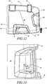
- FIG. 12 and 13 of the accompanying drawings A container in accordance with the second embodiment of the invention is shown in Figures 12 and 13 of the accompanying drawings. This functions in the same manner as the previous example and first embodiment, and equivalent reference numerals have been given to features of the first embodiment.
- a single passage 81 is provided. This corresponds to the second passage 71 of the first embodiment.
- the first passage 70 of the first embodiment is provided by the passage through handle 60 itself - there is no specific passage 70, but the spout 59 can pass through the handle 60 passage and be placed adjacent to the single passage 81, before being slid securely into place.
- Feet 73 are again provided on base 72 for stability.
Landscapes
- Engineering & Computer Science (AREA)
- Mechanical Engineering (AREA)
- Details Of Rigid Or Semi-Rigid Containers (AREA)
Description
- This invention relates to containers for liquid, particularly although non-exclusively for containing fuels.
- The internal combustion engine is ubiquitous in modern society, and brings with it the need to fuel such engines. Whilst it is relatively easy to drive a road vehicle powered by such an engine to a filling station, for garden-based vehicles not adapted for road use, and for petrol driven garden equipment such as lawnmowers, it is inconvenient to do so. As such, it is necessary to use a container, such as a jerry can to transport the fuel from a dispensing point such as a filling station to the equipment in question. Typical fuels include hydrocarbon based fuels such as petrol/gasoline, diesel or ethanol.
- Once full, such containers can be unwieldy - a full 15 litre container will have a mass of around 15 kilograms. As such, it is desirable to provide an ergonomic solution to the handling of such containers.
- It is also known to provide a removable spout to aid in the emptying of such containers. However, this provides a further item that must be carried, and there is a risk that the separate spout can be mislaid.
- A container is known from
FR 438 566 A - A storage position of a spout on a container in the vicinity of a handle is known from
DE 20 2005 006 134 U1 . Here the handle is formed on the top wall of the container. - Into this top wall a bedding for the spout is formed exhibiting a back taper used to fix a spout that is snapped into this bedding.
- A spout itself forming part of the handle piece of a handle for a container is described with
DE 20 2011 050 981 U1 . Whereby the spout forms part of the handle piece in its storage position and is mounted to the container's orifice in working position when pouring liquid. - A container provided with a plurality of handles for ergonomic handling is shown with
US 2010/059536 A1 . The container is having a top and a base with an orifice to connect a spout for discharging liquid from the container lying at one side of its top. A first gripping handle is lying on the base of the container. A lifting-handle lies on the top. The container has a plurality of side walls, including a front wall neighbouring the top at the side with the orifice and a rear wall. A second lifting handle is attached to the rear wall. The gripping handle on the base of the container is formed as a ladder handle that is an arrangement of a set of three single handles spaced on the bottom about a pouring axis of the container. To discharge liquid from the container the user lifts the canister and makes use of the ladder handle in a ladder action by lifting successive handles. - A container to spread grid is known from
DE 297 02 273 U1 that exhibits handles at its front side neighbouring the orifice on its top and at its rear side. The handles at the top and the rear side of the container is formed of a through passage through the body of the container, leaving a generally tubular part which can be grasped by a user for the container to be carried. The handle at the front side is formed as a recessed grip to support the container with one hand from underneath during the spreading action when being carried under the arm, being held on the handle at the container's rear side with the hand of the other arm. -
US 4,069,946 discloses a container and a spout according to the preamble of claim 1. - According to the claimed invention, there is provided a container for liquid, comprising a body defining a void in which liquid can be stored, in which the body has a orifice allowing access into the void, the body being provided with a handle arranged to be grasped by a user, the container being provided with an elongate spout that removably engages the orifice, the handle being provided with a location for storage of the spout, characterized in that the location comprises a first portion of the handle sufficiently wide such that the spout can pass through along its length and a second portion adjacent to the first portion, the spout being able to move from the first portion into the second portion at at least one position along its length, the second portion being narrower than the first portion such that once moved into the second portion, the spout can no longer be removed from the second portion along the length of the spout, and in that the spout comprises a waist providing a local minimum in a width of the spout perpendicular to its length, the waist defining the position at which the spout can be moved into the second portion of the handle.
- As such, this provides a convenient storage location for the spout.
- The handle may comprise a through passage through the body of the container, within which are the first and second positions. With the spout in the second portion, the through passage may be sufficiently large to allow the passage of a user' s hand; as such, the cross-sectional area of the through passage remaining with the spout in the second position preferably may be at least 80 mm by 35mm.
- The body may have a base on which the container can be stably stood, two opposing side faces extending away from the base, the side faces being joined by first and second opposing side walls extending away from the base, the side faces and the side walls being capped by a top wall opposing the base. The orifice may be in the top wall adjacent to one of the side walls with both the first and second side walls being provided with handles arranged to be grasped by a user, the location being in one of the handles. The orifice may extend substantially perpendicular to the base.
- The top wall may also be provided with a handle; this will help with lifting the container, particularly when full of a dense liquid. Each of the handles may comprise a recess in the body. The recess may be a blind recess, which does not pass through the body, or a through recess, which forms a passage through the body. Typically, the handle in the first side wall will be a through recess, and the handle in the second side wall will be a blind
- At least one of the side walls may be provided with a plurality of feet, on which the container may be stably stood. The feet may also extend into, and act to stiffen the side faces. Typically, the second side wall may be provided with the feet. The handle in the second side wall may be provided in one of the feet; this has the advantage that the handle will be located in a particularly sturdy portion of the side wall.
- Typically, the liquid may be a hydrocarbon-based fuel, such as petrol (otherwise known as gasoline), diesel fuel or ethanol. The container may contain the liquid.
- In another example, there is provided a container for liquid, comprising a body defining a void in which liquid can be stored, the body having a base on which the container can be stably stood, two opposing side faces extending away from the base, the side faces being joined by first and second opposing side walls extending away from the base, the side faces and the side walls being capped by a top wall opposing the base, in which the top wall has an orifice adjacent to the first side wall, the orifice allowing access into the void, in which both the first and second side walls are provided with handles arranged to be grasped by a user.
- By providing both handles, the complete emptying of the container has been found to be more ergonomic, particularly with the orifice provided adjacent to the first side wall, therefore being easier to place adjacent to a filler orifice or other such desired location for the liquid when it is being poured out of the container.
- The top wall may also be provided with a handle; this will help with lifting the container, particularly when full of a dense liquid.
- Each of the handles may comprise a recess in the body. The recess may be a blind recess, which does not pass through the body, or a through recess, which forms a passage through the body. Typically, the handle in the first side wall will be a through recess, and the handle in the second side wall will be a blind recess.
- The container is provided with an elongate spout that can removably engage the orifice. This will assist in dispensing the liquid. One of the handles is provided with a location for storage of the spout, particularly a handle provided as a through recess such as that in the first side wall.
- The orifice may extend substantially perpendicular to the base. This has the advantages that:
- when filling liquid into a tank the position of the spout can still be observed, as it is not obstructed by the body, as in the case of a 45° angled spout
- the filling of liquid is still possible even if the orifice of a tank is close to a wall
- when positioning the spout at the orifice of a tank, the spout's position can easily be seen; with a 45° spout one would have to turn the canister for positioning.
- The location comprises a first portion of the handle sufficiently wide such that the spout can pass through along its length and a second portion adjacent to the first portion, the spout being able to move from the first portion into the second portion at at least one position along its length, the second portion being narrower than the first portion such that once moved into the second portion, the spout can no longer be removed from the second portion along the length of the spout. This provides a convenient storage for the spout.
- The spout comprises a waist providing a local minimum in a width of the spout perpendicular to its length, the waist defining the position at which the spout can be moved into the second portion of the handle.
- At least one of the side walls may be provided with a plurality of feet, on which the container may be stably stood. The feet may also extend into, and act to stiffen the side faces. Typically, the second side wall may be provided with the feet. The handle in the second side wall may be provided in one of the feet; this has the advantage that the handle will be located in a particularly sturdy portion of the side wall.
- Typically, the liquid may be a hydrocarbon-based fuel, such as petrol (otherwise known as gasoline), diesel fuel or ethanol. The container may contain the liquid.
- The container of this example or of the claimed invention may be provided with a stopper, arranged so as to block the orifice when the spout is not being used.
- The orifice of this example or the claimed invention may be the only access into the void.
- There now follows, by way of example only, description of embodiments of the invention, described with reference to the accompanying drawings, in which:
-
Figure 1 shows a side elevation of a container for petroleum spirit which is not part of the present invention; -
Figure 2 shows a perspective view of the container ofFigure 1 ; -
Figure 3 shows a view of a user emptying the container ofFigure 1 ; -
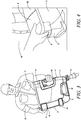
Figure 4 shows a close up view ofFigure 3 , showing one of the handles; -
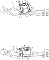
Figure 5 shows a view of the user carrying the container ofFigure 1 in an upright position; -
Figure 6 shows a view of the user carrying the container ofFigure 1 in a rotated position; -
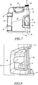
Figure 7 show a side view of a container for petroleum spirit in accordance with a first embodiment of the invention; -
Figure 8 shows a close up perspective view of the handles of the container ofFigure 7 ; -
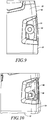
Figure 9 shows a side view of the handle ofFigure 8 , with a spout inserted therethrough; -
Figure 10 shows a perspective view of the handle ofFigure 8 , with the spout stowed in the handle; -
Figure 11 shows a side view of the container ofFigure 7 (from a position rotated through 90 degrees with respect toFigure 9 ), with the spout stowed in the handle; -
Figure 12 shows a side view of a container for petroleum spirit in accordance with a second embodiment of the invention; and -
Figure 13 shows a perspective view of the handle of the container ofFigure 12 . - A container for a hydrocarbon-based fuel, such as petrol, otherwise known as gasoline, diesel fuel or ethanol, such as may be used with a ride-on mower or other petrol-driven garden equipment in accordance with an example which does not form part of the present invention is shown in
Figures 1 to 6 of the accompanying drawings. The container 1 has a base 2 (on which the container 1 can be stood) and two opposing side faces 3 (only one of which can be seen in the drawings - the container is generally symmetric about a central plane parallel to the side faces, and so theside face 3 furthest from the viewpoints of the drawings corresponds to that which can be seen) extending from thebase 2. The side faces 3 are joined by opposing first side wall 4 andsecond side wall 5 which both also extend frombase 2. The side faces 3 andside walls 4, 5 are capped by atop wall 6. The side faces 3,side walls 4, 5,base 2 andtop wall 6 therefore define a body having a void 7 therein in which petroleum spirit can be stored. - The
top wall 6 has anorifice 8 which allows the container to be filled or emptied. Theorifice 8 is adjacent to the first side wall 4 and extends perpendicularly to thebase 2. The container 1 is also provided with aremovable spout 9 which can engage thisorifice 8. - The
side walls 4, 5 are both provided withhandles handle 10 in the first side wall 4 is of the form of a through passage through the body of the container 1, leaving a generally tubular part which can be grasped by auser 12. Thehandle 11 in thesecond side wall 5 is of the form of a recess sufficiently close to thebase 2 that theuser 12 can place his fingers in the recess whilst grasping onto the base 2 (as shown inFigure 4 of the accompanying drawings). - There is also a
further handle 13 provided as a through passage in thetop wall 6; again, a through passage is provided in the body of the container, leaving a tubular part for the user to grasp. - As such, the
handles - The
handles side walls 4, 5 make it much easier for theuser 12 to invert the container (as shown inFigures 3 and 4 of the accompanying drawings) whilst still providing the container with support whilst it is emptied. Furthermore, given that thetop wall 6 is elongate in the direction from the first side wall 4 to thesecond side wall 5, having theorifice 8 at an edge of thetop wall 6 adjacent to the first side wall 4 means that it will be easier to offer up the orifice and/or thespout 9 to a filling cap in a small vehicle such as ride-on mower, where the filling cap is often in an awkward position such as immediately adjacent to the seat. - The
handle 13 in thetop wall 6 provides a convenient way that the container can be carried, as shown inFigure 5 of the accompanying drawings, whilstFigure 6 shows that thehandle 10 in the first side wall 4 can also be used in a rotated orientation of the container 1. - The
second side wall 5 is also provided with twofeet 14, which serve several purposes. Firstly, the container 1 can be stood on thefeet 14, so that the container is stable with thesecond side wall 5 downwards. Secondly, thefeet 14 can serve to stiffen the container 1, and in particular the side faces 3. Thirdly, thefoot 14 adjacent to thebase 2 can house thehandle 11 in thesecond side wall 5; this is advantageous as it allows thehandle 11 to be in a particularly sturdy portion of the container 1. -
Feet 22 are also provided on thebase 2 for stability. - A
container 51 in accordance with the first embodiment of the invention is shown inFigures 8 to 11 of the accompanying drawings. Equivalent integers to the first example have been referenced with equivalent reference numerals, raised by 50. Thecontainer 51 with itshandles spout 59 can be stored in thehandle 60 in thefirst side wall 54. - As such, the through passage of
handle 60 is provided with twoadjacent passages spout 59. The first,larger passage 70 through thehandle 60 is large enough that thespout 59 can pass along the entirety of its length through thepassage 70. The second,smaller passage 71 can surround a narrow waist of thespout 59 but will not otherwise allow thespout 59 to move along its length. - As such, the
spout 59 can be introduced into thefirst passage 70, as shown inFigure 9 of the accompanying drawings. It is passed through until the narrow waist is in thefirst passage 70; thespout 59 is then slid sideways, perpendicular to the length of thespout 59, until the narrow waist is in the second passage 71 (as shown inFigures 10 and11 of the accompanying drawings). Because the narrow waist cannot escape thesecond passage 71 lengthways, thespout 59 is now securely stored in thehandle 60. Furthermore, thehandle 60 is still wide enough so that the user can pass his hand through thehandle 60, in order to pick up the container. -
Feet 65 are also provided on thebase 52 for stability. - A container in accordance with the second embodiment of the invention is shown in
Figures 12 and 13 of the accompanying drawings. This functions in the same manner as the previous example and first embodiment, and equivalent reference numerals have been given to features of the first embodiment. - In this embodiment, rather than having two
passages single passage 81 is provided. This corresponds to thesecond passage 71 of the first embodiment. Thefirst passage 70 of the first embodiment is provided by the passage throughhandle 60 itself - there is nospecific passage 70, but thespout 59 can pass through thehandle 60 passage and be placed adjacent to thesingle passage 81, before being slid securely into place. -
Feet 73 are again provided onbase 72 for stability.
Claims (7)
- A container (51) for liquid,
comprising a body defining a void (57) in which liquid can be stored, in which the body has an orifice (58) allowing access into the void (57),
the body being provided with a handle (60, 63) arranged to be grasped by a user (12),
the container (51) being provided with an elongate spout (59) that can removably engage the orifice (58),
the handle (60) being provided with a location for storage of the spout (59),
the location comprising a first portion (70) of the handle (60) sufficiently wide such that the spout (59) can pass through along its length and a second portion (71; 81) adjacent to the first portion (70), the spout (59) being able to move from the first portion (70) into the second portion (71; 81) at at least one position along its length, the second portion (71; 81) being narrower than the first portion (70), spout (59) comprising a waist providing a local minimum in a width of the spout (59) perpendicular to its length, the waist defining the position at which the spout (59) can be moved into the second portion (71; 81) of the handle, characterized in that once moved into the second portion (71; 81), the spout (59) can no longer be removed from the second portion (71; 81) along the length of the spout (59). - The container of claim 1, in which the handle (60) comprises a through passage through the body of the container (51), within which are the first and second positions (70, 71; 81), in which, with the spout (59) in the second position (71; 81), the through passage is sufficiently large to allow the passage of a user's hand.
- The container of any preceding claim, in which the body has a base (52; 72) on which the container (51) can be stably stood and two opposing side faces (53) extending away from the base (52; 72), the side faces (53) being joined by first and second opposing side walls (54, 55) extending away from the base (52; 72), the side faces (53) and the side walls (54, 55) being capped by a top wall (56) opposing the base (52; 72), the orifice (58) being in the top wall (56) adjacent to one of the side walls (54, 55) with both the first and second side walls (54, 55) being provided with handles (60, 61) arranged to be grasped by a user (12), the location being in one of the handles (60, 61) in the first and second side walls (54, 55).
- The container of claim 3, in which the top wall (56) is provided with a handle (63).
- The container of claim 3 or claim 4, in which at least one of the side walls (55) is provided with a plurality of feet (64), on which the container can be stably stood.
- The container of claim 5, in which the feet (64) extend into, and act to stiffen, the side faces (53).
- The container of claim 5 or claim 6 in which the second side wall (55) is provided with the feet (64), the handle (61) in the second side wall (55) being provided in one of the feet (64).
Applications Claiming Priority (1)
| Application Number | Priority Date | Filing Date | Title |
|---|---|---|---|
| PCT/EP2012/068439 WO2014044306A1 (en) | 2012-09-19 | 2012-09-19 | Containers for liquid |
Publications (2)
| Publication Number | Publication Date |
|---|---|
| EP2897875A1 EP2897875A1 (en) | 2015-07-29 |
| EP2897875B1 true EP2897875B1 (en) | 2017-02-01 |
Family
ID=46968184
Family Applications (1)
| Application Number | Title | Priority Date | Filing Date |
|---|---|---|---|
| EP12766945.5A Active EP2897875B1 (en) | 2012-09-19 | 2012-09-19 | Container handle with spout attachment |
Country Status (5)
| Country | Link |
|---|---|
| US (1) | US9334085B2 (en) |
| EP (1) | EP2897875B1 (en) |
| CN (1) | CN104661926B (en) |
| AU (1) | AU2012390584B2 (en) |
| WO (1) | WO2014044306A1 (en) |
Families Citing this family (14)
| Publication number | Priority date | Publication date | Assignee | Title |
|---|---|---|---|---|
| MX374650B (en) * | 2013-11-15 | 2025-03-06 | Johnson & Son Inc S C | BOWL. |
| DE102014212601A1 (en) | 2014-06-30 | 2015-12-31 | Henkel Ag & Co. Kgaa | Liquid detergent container and method for metered dispensing of detergent from the container |
| US9669959B2 (en) * | 2015-03-26 | 2017-06-06 | Bway Corporation | Container with integrated handles |
| US10131467B2 (en) | 2015-03-26 | 2018-11-20 | Bway Corporation | Container with integrated handles |
| USD778519S1 (en) | 2015-03-26 | 2017-02-07 | Bway Corporation | Container with integrated handles |
| US9834371B2 (en) * | 2015-09-28 | 2017-12-05 | Lucy Pet Products, Llc | Cat litter container with two handles and a pouring spout |
| ITUB201586582U1 (en) * | 2015-10-22 | 2017-04-22 | Ali Group S R L | "TRANSPORTABLE TECHNICAL CONTAINER FOR CHEMICAL LIQUIDS" |
| USD839098S1 (en) * | 2016-03-09 | 2019-01-29 | Sk Lubricants Co., Ltd. | Lubricant container |
| SG10201811165VA (en) | 2018-12-13 | 2020-07-29 | Proof & Company Spirits Pte Ltd | Vessel assembly |
| USD887277S1 (en) * | 2020-01-31 | 2020-06-16 | Phillips 66 Company | Oil bottle |
| US12497211B2 (en) * | 2021-02-26 | 2025-12-16 | Regent Aubin | Stackable fluid container with double top handle |
| US12583648B2 (en) | 2024-01-17 | 2026-03-24 | Black & Decker Inc. | Portable fluid tank system with mounting assembly |
| US12654908B2 (en) | 2024-01-17 | 2026-06-16 | Black & Decker Inc. | Portable fluid tank system with angled spill face |
| US12565885B2 (en) | 2024-01-17 | 2026-03-03 | Black & Decker Inc. | Portable fluid tank system with multi-state control interface and remote operation |
Citations (1)
| Publication number | Priority date | Publication date | Assignee | Title |
|---|---|---|---|---|
| US4069946A (en) * | 1977-01-03 | 1978-01-24 | Justrite Manufacturing Company | Consumer safety container for inflammables |
Family Cites Families (35)
| Publication number | Priority date | Publication date | Assignee | Title |
|---|---|---|---|---|
| FR438566A (en) * | 1911-12-30 | 1912-05-21 | Sylvain Wolf | Burette can |
| US2517115A (en) | 1946-03-02 | 1950-08-01 | Keily Henry Joseph | Crossword puzzle book |
| US3250434A (en) * | 1964-07-06 | 1966-05-10 | Dunlop Rubber Australia Ltd | Electrolyte container for dry charge batteries |
| US3845884A (en) | 1973-06-05 | 1974-11-05 | Hall & Myers | Bottle with an inverted portion support and sealing ring |
| JPS5533946Y2 (en) * | 1976-07-22 | 1980-08-12 | ||
| US4392594A (en) * | 1980-08-27 | 1983-07-12 | Dart Industries Inc. | Watering can |
| USD271113S (en) | 1981-07-09 | 1983-10-25 | Minnesota Mining & Manufacturing Company | Chemical container |
| FR2549012B1 (en) | 1983-07-11 | 1985-10-31 | Seprosy | BOTTLE EQUIPPED WITH A SPOUT |
| US4541529A (en) * | 1983-07-19 | 1985-09-17 | Bomatic, Inc. | Blow molded container and supplemental handle therefor |
| US4658975A (en) | 1985-08-30 | 1987-04-21 | Cone Robert L | Liquid container with handle |
| US4834269A (en) * | 1985-08-30 | 1989-05-30 | Cone Robert L | Liquid container |
| US4804119A (en) | 1985-12-06 | 1989-02-14 | Goodall Donald T | Liquid dispenser |
| USD303496S (en) | 1986-09-11 | 1989-09-19 | Bmr Investments, Inc. | Bottle |
| US4923098A (en) | 1987-03-30 | 1990-05-08 | Schoonover Michael I | Fluid container |
| US4969571A (en) | 1988-06-14 | 1990-11-13 | Innovative Technology Inc. | Container for fluids |
| CH680064A5 (en) * | 1989-12-04 | 1992-06-15 | Wolfram Dr Schiemann | |
| US5226574A (en) | 1991-08-16 | 1993-07-13 | Durinzi Jr Armando F | Portable dispensing container for liquid fuel |
| DE29702273U1 (en) * | 1997-02-10 | 1997-04-10 | COMPO GmbH, 48157 Münster | Device for storing and distributing particles on a surface |
| US6237792B1 (en) | 1999-01-19 | 2001-05-29 | State Industrial Products | Reinforced bottle having integral handles |
| US6397902B1 (en) | 2001-04-25 | 2002-06-04 | Michael J. Murphy | High speed nozzle with vapor recovery |
| US6832705B2 (en) | 2002-09-19 | 2004-12-21 | Nathan Hollander | Liquid container with handles |
| US7097061B2 (en) * | 2003-08-14 | 2006-08-29 | Graham Packaging Pet Technologies Inc. | Plastic container which is hot-fillable and/or having neck finish adapted for receipt of handle |
| USD528424S1 (en) | 2004-02-20 | 2006-09-19 | Graham Packaging Company, L.P. | Container |
| JP2005289513A (en) | 2004-04-05 | 2005-10-20 | Junichi Yamada | Portable polyethylene tank |
| US7182214B2 (en) * | 2004-08-19 | 2007-02-27 | Plastipak Packaging, Inc. | Plastic container including an upper grip portion |
| DE202005006134U1 (en) * | 2005-04-15 | 2005-06-23 | Dienes Packaging Gmbh | Jerrycan for storing and transporting of free flowing material such as engine oil has on upper side a slot accessible from outside and with shape conforming at least in sections to pouring out aid |
| DE202005013559U1 (en) | 2005-08-27 | 2006-01-05 | Kriebelt, Johann | Petrol can has recess near its base, into which additional handle is welded |
| USD573885S1 (en) | 2007-07-12 | 2008-07-29 | Berlin Packaging, Llc | Container |
| US20100059536A1 (en) * | 2008-09-09 | 2010-03-11 | Terry Stolk | Multi-handled jerry can |
| USD595583S1 (en) | 2008-12-03 | 2009-07-07 | Plastipak Packaging, Inc. | Plastic container |
| US20100155434A1 (en) | 2008-12-23 | 2010-06-24 | Bart Bradford | Portable Container for Dispensing Fuel |
| MX2010003170A (en) | 2009-03-23 | 2010-09-27 | Dean Intellectual Property Ser | Liquid container: system and method for use and distribution thereof. |
| EP2363348A1 (en) * | 2010-03-04 | 2011-09-07 | Marco Camoli | Tank for fuel, oil and similar with pivoting handle and angled, flexible and steerable pourer |
| KR20110009074U (en) * | 2010-03-17 | 2011-09-23 | 씨제이제일제당 (주) | Fluid storage tank |
| DE202011050981U1 (en) * | 2011-08-12 | 2011-10-13 | Dienes Packaging Gmbh | Canister with detachable spout |
-
2012
- 2012-09-19 WO PCT/EP2012/068439 patent/WO2014044306A1/en not_active Ceased
- 2012-09-19 AU AU2012390584A patent/AU2012390584B2/en active Active
- 2012-09-19 US US14/429,569 patent/US9334085B2/en active Active
- 2012-09-19 CN CN201280075882.7A patent/CN104661926B/en active Active
- 2012-09-19 EP EP12766945.5A patent/EP2897875B1/en active Active
Patent Citations (1)
| Publication number | Priority date | Publication date | Assignee | Title |
|---|---|---|---|---|
| US4069946A (en) * | 1977-01-03 | 1978-01-24 | Justrite Manufacturing Company | Consumer safety container for inflammables |
Also Published As
| Publication number | Publication date |
|---|---|
| US20150225124A1 (en) | 2015-08-13 |
| AU2012390584A1 (en) | 2015-03-12 |
| CN104661926B (en) | 2017-05-24 |
| EP2897875A1 (en) | 2015-07-29 |
| US9334085B2 (en) | 2016-05-10 |
| CN104661926A (en) | 2015-05-27 |
| WO2014044306A1 (en) | 2014-03-27 |
| AU2012390584B2 (en) | 2017-06-01 |
Similar Documents
| Publication | Publication Date | Title |
|---|---|---|
| AU2012390584B2 (en) | Containers for liquid | |
| US4125207A (en) | Chain saw servicing kit | |
| US4811870A (en) | Liquid container with rotatable spout | |
| CA2588740C (en) | Apparatus for secure transport of containers | |
| US5139278A (en) | Versatile fuel container | |
| US20090045226A1 (en) | Fuel dispenser system | |
| US20100155434A1 (en) | Portable Container for Dispensing Fuel | |
| US20180346177A1 (en) | Baffled cross-through liquid container | |
| NO340153B1 (en) | Container with lid | |
| US7344052B2 (en) | Apparatus for storing and dispensing liquids | |
| US20130334254A1 (en) | Portable Fuel Container with Attachment Means | |
| US9242843B2 (en) | Funnel for transferring fluids | |
| US9302809B1 (en) | Stackable, stabilized fuel containers | |
| US9527650B2 (en) | Chambered container for the mixing and storage of fluids | |
| US9199770B2 (en) | Portable fuel container system with attachment means and associated methods | |
| CN204126993U (en) | A kind of portable fuel tank handle | |
| US20100059536A1 (en) | Multi-handled jerry can | |
| US6663152B2 (en) | Detachable extension handle | |
| US10676335B1 (en) | Diesel exhaust fluid funnel | |
| US20210039939A1 (en) | Funnel system for a gas tank | |
| JP3069156U (en) | Plastic tank | |
| US20250187754A1 (en) | Pre-Flight Caddy | |
| US20100051634A1 (en) | Container suspension device | |
| WO2019023734A1 (en) | Portable liquid container and method of use | |
| US20140034687A1 (en) | Pour spout and dispensing device |
Legal Events
| Date | Code | Title | Description |
|---|---|---|---|
| PUAI | Public reference made under article 153(3) epc to a published international application that has entered the european phase |
Free format text: ORIGINAL CODE: 0009012 |
|
| 17P | Request for examination filed |
Effective date: 20150319 |
|
| AK | Designated contracting states |
Kind code of ref document: A1 Designated state(s): AL AT BE BG CH CY CZ DE DK EE ES FI FR GB GR HR HU IE IS IT LI LT LU LV MC MK MT NL NO PL PT RO RS SE SI SK SM TR |
|
| AX | Request for extension of the european patent |
Extension state: BA ME |
|
| DAX | Request for extension of the european patent (deleted) | ||
| 17Q | First examination report despatched |
Effective date: 20160324 |
|
| GRAP | Despatch of communication of intention to grant a patent |
Free format text: ORIGINAL CODE: EPIDOSNIGR1 |
|
| INTG | Intention to grant announced |
Effective date: 20160901 |
|
| GRAS | Grant fee paid |
Free format text: ORIGINAL CODE: EPIDOSNIGR3 |
|
| GRAA | (expected) grant |
Free format text: ORIGINAL CODE: 0009210 |
|
| AK | Designated contracting states |
Kind code of ref document: B1 Designated state(s): AL AT BE BG CH CY CZ DE DK EE ES FI FR GB GR HR HU IE IS IT LI LT LU LV MC MK MT NL NO PL PT RO RS SE SI SK SM TR |
|
| REG | Reference to a national code |
Ref country code: GB Ref legal event code: FG4D |
|
| REG | Reference to a national code |
Ref country code: CH Ref legal event code: EP Ref country code: AT Ref legal event code: REF Ref document number: 865353 Country of ref document: AT Kind code of ref document: T Effective date: 20170215 |
|
| REG | Reference to a national code |
Ref country code: IE Ref legal event code: FG4D |
|
| REG | Reference to a national code |
Ref country code: DE Ref legal event code: R096 Ref document number: 602012028318 Country of ref document: DE |
|
| REG | Reference to a national code |
Ref country code: SE Ref legal event code: TRGR |
|
| REG | Reference to a national code |
Ref country code: NL Ref legal event code: MP Effective date: 20170201 |
|
| REG | Reference to a national code |
Ref country code: LT Ref legal event code: MG4D |
|
| REG | Reference to a national code |
Ref country code: AT Ref legal event code: MK05 Ref document number: 865353 Country of ref document: AT Kind code of ref document: T Effective date: 20170201 |
|
| PG25 | Lapsed in a contracting state [announced via postgrant information from national office to epo] |
Ref country code: LT Free format text: LAPSE BECAUSE OF FAILURE TO SUBMIT A TRANSLATION OF THE DESCRIPTION OR TO PAY THE FEE WITHIN THE PRESCRIBED TIME-LIMIT Effective date: 20170201 Ref country code: HR Free format text: LAPSE BECAUSE OF FAILURE TO SUBMIT A TRANSLATION OF THE DESCRIPTION OR TO PAY THE FEE WITHIN THE PRESCRIBED TIME-LIMIT Effective date: 20170201 Ref country code: FI Free format text: LAPSE BECAUSE OF FAILURE TO SUBMIT A TRANSLATION OF THE DESCRIPTION OR TO PAY THE FEE WITHIN THE PRESCRIBED TIME-LIMIT Effective date: 20170201 Ref country code: IS Free format text: LAPSE BECAUSE OF FAILURE TO SUBMIT A TRANSLATION OF THE DESCRIPTION OR TO PAY THE FEE WITHIN THE PRESCRIBED TIME-LIMIT Effective date: 20170601 Ref country code: GR Free format text: LAPSE BECAUSE OF FAILURE TO SUBMIT A TRANSLATION OF THE DESCRIPTION OR TO PAY THE FEE WITHIN THE PRESCRIBED TIME-LIMIT Effective date: 20170502 Ref country code: NO Free format text: LAPSE BECAUSE OF FAILURE TO SUBMIT A TRANSLATION OF THE DESCRIPTION OR TO PAY THE FEE WITHIN THE PRESCRIBED TIME-LIMIT Effective date: 20170501 |
|
| REG | Reference to a national code |
Ref country code: FR Ref legal event code: PLFP Year of fee payment: 6 |
|
| PG25 | Lapsed in a contracting state [announced via postgrant information from national office to epo] |
Ref country code: PT Free format text: LAPSE BECAUSE OF FAILURE TO SUBMIT A TRANSLATION OF THE DESCRIPTION OR TO PAY THE FEE WITHIN THE PRESCRIBED TIME-LIMIT Effective date: 20170601 Ref country code: PL Free format text: LAPSE BECAUSE OF FAILURE TO SUBMIT A TRANSLATION OF THE DESCRIPTION OR TO PAY THE FEE WITHIN THE PRESCRIBED TIME-LIMIT Effective date: 20170201 Ref country code: LV Free format text: LAPSE BECAUSE OF FAILURE TO SUBMIT A TRANSLATION OF THE DESCRIPTION OR TO PAY THE FEE WITHIN THE PRESCRIBED TIME-LIMIT Effective date: 20170201 Ref country code: AT Free format text: LAPSE BECAUSE OF FAILURE TO SUBMIT A TRANSLATION OF THE DESCRIPTION OR TO PAY THE FEE WITHIN THE PRESCRIBED TIME-LIMIT Effective date: 20170201 Ref country code: RS Free format text: LAPSE BECAUSE OF FAILURE TO SUBMIT A TRANSLATION OF THE DESCRIPTION OR TO PAY THE FEE WITHIN THE PRESCRIBED TIME-LIMIT Effective date: 20170201 Ref country code: NL Free format text: LAPSE BECAUSE OF FAILURE TO SUBMIT A TRANSLATION OF THE DESCRIPTION OR TO PAY THE FEE WITHIN THE PRESCRIBED TIME-LIMIT Effective date: 20170201 Ref country code: ES Free format text: LAPSE BECAUSE OF FAILURE TO SUBMIT A TRANSLATION OF THE DESCRIPTION OR TO PAY THE FEE WITHIN THE PRESCRIBED TIME-LIMIT Effective date: 20170201 Ref country code: BG Free format text: LAPSE BECAUSE OF FAILURE TO SUBMIT A TRANSLATION OF THE DESCRIPTION OR TO PAY THE FEE WITHIN THE PRESCRIBED TIME-LIMIT Effective date: 20170501 |
|
| PG25 | Lapsed in a contracting state [announced via postgrant information from national office to epo] |
Ref country code: SK Free format text: LAPSE BECAUSE OF FAILURE TO SUBMIT A TRANSLATION OF THE DESCRIPTION OR TO PAY THE FEE WITHIN THE PRESCRIBED TIME-LIMIT Effective date: 20170201 Ref country code: IT Free format text: LAPSE BECAUSE OF FAILURE TO SUBMIT A TRANSLATION OF THE DESCRIPTION OR TO PAY THE FEE WITHIN THE PRESCRIBED TIME-LIMIT Effective date: 20170201 Ref country code: RO Free format text: LAPSE BECAUSE OF FAILURE TO SUBMIT A TRANSLATION OF THE DESCRIPTION OR TO PAY THE FEE WITHIN THE PRESCRIBED TIME-LIMIT Effective date: 20170201 Ref country code: EE Free format text: LAPSE BECAUSE OF FAILURE TO SUBMIT A TRANSLATION OF THE DESCRIPTION OR TO PAY THE FEE WITHIN THE PRESCRIBED TIME-LIMIT Effective date: 20170201 Ref country code: CZ Free format text: LAPSE BECAUSE OF FAILURE TO SUBMIT A TRANSLATION OF THE DESCRIPTION OR TO PAY THE FEE WITHIN THE PRESCRIBED TIME-LIMIT Effective date: 20170201 |
|
| REG | Reference to a national code |
Ref country code: DE Ref legal event code: R097 Ref document number: 602012028318 Country of ref document: DE |
|
| PG25 | Lapsed in a contracting state [announced via postgrant information from national office to epo] |
Ref country code: SM Free format text: LAPSE BECAUSE OF FAILURE TO SUBMIT A TRANSLATION OF THE DESCRIPTION OR TO PAY THE FEE WITHIN THE PRESCRIBED TIME-LIMIT Effective date: 20170201 Ref country code: DK Free format text: LAPSE BECAUSE OF FAILURE TO SUBMIT A TRANSLATION OF THE DESCRIPTION OR TO PAY THE FEE WITHIN THE PRESCRIBED TIME-LIMIT Effective date: 20170201 |
|
| PLBE | No opposition filed within time limit |
Free format text: ORIGINAL CODE: 0009261 |
|
| STAA | Information on the status of an ep patent application or granted ep patent |
Free format text: STATUS: NO OPPOSITION FILED WITHIN TIME LIMIT |
|
| 26N | No opposition filed |
Effective date: 20171103 |
|
| PG25 | Lapsed in a contracting state [announced via postgrant information from national office to epo] |
Ref country code: SI Free format text: LAPSE BECAUSE OF FAILURE TO SUBMIT A TRANSLATION OF THE DESCRIPTION OR TO PAY THE FEE WITHIN THE PRESCRIBED TIME-LIMIT Effective date: 20170201 |
|
| REG | Reference to a national code |
Ref country code: CH Ref legal event code: PL |
|
| PG25 | Lapsed in a contracting state [announced via postgrant information from national office to epo] |
Ref country code: MC Free format text: LAPSE BECAUSE OF FAILURE TO SUBMIT A TRANSLATION OF THE DESCRIPTION OR TO PAY THE FEE WITHIN THE PRESCRIBED TIME-LIMIT Effective date: 20170201 |
|
| REG | Reference to a national code |
Ref country code: IE Ref legal event code: MM4A |
|
| REG | Reference to a national code |
Ref country code: BE Ref legal event code: MM Effective date: 20170930 |
|
| PG25 | Lapsed in a contracting state [announced via postgrant information from national office to epo] |
Ref country code: LU Free format text: LAPSE BECAUSE OF NON-PAYMENT OF DUE FEES Effective date: 20170919 |
|
| PG25 | Lapsed in a contracting state [announced via postgrant information from national office to epo] |
Ref country code: IE Free format text: LAPSE BECAUSE OF NON-PAYMENT OF DUE FEES Effective date: 20170919 Ref country code: LI Free format text: LAPSE BECAUSE OF NON-PAYMENT OF DUE FEES Effective date: 20170930 Ref country code: CH Free format text: LAPSE BECAUSE OF NON-PAYMENT OF DUE FEES Effective date: 20170930 |
|
| REG | Reference to a national code |
Ref country code: FR Ref legal event code: PLFP Year of fee payment: 7 |
|
| PG25 | Lapsed in a contracting state [announced via postgrant information from national office to epo] |
Ref country code: BE Free format text: LAPSE BECAUSE OF NON-PAYMENT OF DUE FEES Effective date: 20170930 |
|
| PG25 | Lapsed in a contracting state [announced via postgrant information from national office to epo] |
Ref country code: MT Free format text: LAPSE BECAUSE OF NON-PAYMENT OF DUE FEES Effective date: 20170919 |
|
| PG25 | Lapsed in a contracting state [announced via postgrant information from national office to epo] |
Ref country code: HU Free format text: LAPSE BECAUSE OF FAILURE TO SUBMIT A TRANSLATION OF THE DESCRIPTION OR TO PAY THE FEE WITHIN THE PRESCRIBED TIME-LIMIT; INVALID AB INITIO Effective date: 20120919 |
|
| PG25 | Lapsed in a contracting state [announced via postgrant information from national office to epo] |
Ref country code: CY Free format text: LAPSE BECAUSE OF FAILURE TO SUBMIT A TRANSLATION OF THE DESCRIPTION OR TO PAY THE FEE WITHIN THE PRESCRIBED TIME-LIMIT Effective date: 20170201 |
|
| PG25 | Lapsed in a contracting state [announced via postgrant information from national office to epo] |
Ref country code: MK Free format text: LAPSE BECAUSE OF FAILURE TO SUBMIT A TRANSLATION OF THE DESCRIPTION OR TO PAY THE FEE WITHIN THE PRESCRIBED TIME-LIMIT Effective date: 20170201 |
|
| PG25 | Lapsed in a contracting state [announced via postgrant information from national office to epo] |
Ref country code: TR Free format text: LAPSE BECAUSE OF FAILURE TO SUBMIT A TRANSLATION OF THE DESCRIPTION OR TO PAY THE FEE WITHIN THE PRESCRIBED TIME-LIMIT Effective date: 20170201 |
|
| PG25 | Lapsed in a contracting state [announced via postgrant information from national office to epo] |
Ref country code: AL Free format text: LAPSE BECAUSE OF FAILURE TO SUBMIT A TRANSLATION OF THE DESCRIPTION OR TO PAY THE FEE WITHIN THE PRESCRIBED TIME-LIMIT Effective date: 20170201 |
|
| P01 | Opt-out of the competence of the unified patent court (upc) registered |
Effective date: 20230419 |
|
| PGFP | Annual fee paid to national office [announced via postgrant information from national office to epo] |
Ref country code: DE Payment date: 20250806 Year of fee payment: 14 |
|
| PGFP | Annual fee paid to national office [announced via postgrant information from national office to epo] |
Ref country code: GB Payment date: 20250805 Year of fee payment: 14 |
|
| PGFP | Annual fee paid to national office [announced via postgrant information from national office to epo] |
Ref country code: FR Payment date: 20250807 Year of fee payment: 14 |
|
| PGFP | Annual fee paid to national office [announced via postgrant information from national office to epo] |
Ref country code: SE Payment date: 20250805 Year of fee payment: 14 |