EP2897392A1 - Mobile communication system, data communication method, gateway device, and base station - Google Patents
Mobile communication system, data communication method, gateway device, and base station Download PDFInfo
- Publication number
- EP2897392A1 EP2897392A1 EP13837842.7A EP13837842A EP2897392A1 EP 2897392 A1 EP2897392 A1 EP 2897392A1 EP 13837842 A EP13837842 A EP 13837842A EP 2897392 A1 EP2897392 A1 EP 2897392A1
- Authority
- EP
- European Patent Office
- Prior art keywords
- data
- bearer
- transmits
- transmitting
- gateway device
- Prior art date
- Legal status (The legal status is an assumption and is not a legal conclusion. Google has not performed a legal analysis and makes no representation as to the accuracy of the status listed.)
- Withdrawn
Links
Images


















Classifications
-
- H—ELECTRICITY
- H04—ELECTRIC COMMUNICATION TECHNIQUE
- H04W—WIRELESS COMMUNICATION NETWORKS
- H04W4/00—Services specially adapted for wireless communication networks; Facilities therefor
- H04W4/70—Services for machine-to-machine communication [M2M] or machine type communication [MTC]
-
- H—ELECTRICITY
- H04—ELECTRIC COMMUNICATION TECHNIQUE
- H04W—WIRELESS COMMUNICATION NETWORKS
- H04W28/00—Network traffic management; Network resource management
- H04W28/02—Traffic management, e.g. flow control or congestion control
- H04W28/0215—Traffic management, e.g. flow control or congestion control based on user or device properties, e.g. MTC-capable devices
-
- H—ELECTRICITY
- H04—ELECTRIC COMMUNICATION TECHNIQUE
- H04W—WIRELESS COMMUNICATION NETWORKS
- H04W92/00—Interfaces specially adapted for wireless communication networks
- H04W92/16—Interfaces between hierarchically similar devices
- H04W92/24—Interfaces between hierarchically similar devices between backbone network devices
-
- H—ELECTRICITY
- H04—ELECTRIC COMMUNICATION TECHNIQUE
- H04W—WIRELESS COMMUNICATION NETWORKS
- H04W4/00—Services specially adapted for wireless communication networks; Facilities therefor
- H04W4/20—Services signaling; Auxiliary data signalling, i.e. transmitting data via a non-traffic channel
-
- H—ELECTRICITY
- H04—ELECTRIC COMMUNICATION TECHNIQUE
- H04W—WIRELESS COMMUNICATION NETWORKS
- H04W88/00—Devices specially adapted for wireless communication networks, e.g. terminals, base stations or access point devices
- H04W88/08—Access point devices
-
- H—ELECTRICITY
- H04—ELECTRIC COMMUNICATION TECHNIQUE
- H04W—WIRELESS COMMUNICATION NETWORKS
- H04W88/00—Devices specially adapted for wireless communication networks, e.g. terminals, base stations or access point devices
- H04W88/16—Gateway arrangements
Definitions
- a mobile communication system includes a first gateway device that transmits user data with a base station, and a second gateway device that transmits the user data with the first gateway device and an external network, wherein the first gateway device and the second gateway device transmit a small amount of data autonomously transmitted from a terminal device through the base station by using a communication resource for transmitting a control signal, not a communication resource for transmitting user data, between the first gateway device and the second gateway device.
- the configuration of the mobile communication system shown in Fig. 1 is an example of using LTE (Long Term Evolution) specified in the 3GPP for an access network.
- the mobile communication system shown in Fig. 1 includes UE (User Equipment) 10, eNodeB (enhanced Node B) 20, MME (Mobility Management Entity) 30, SGW (Serving Gateway) 40 and PGW (Packet Data Network Gateway) 50.
- UE User Equipment
- eNodeB enhanced Node B
- MME Mobility Management Entity
- SGW Serving Gateway
- PGW Packet Data Network Gateway
- a dedicated bearer for transmitting a large amount of data is set between the SGW 40 and the PGW 50, and by transmitting the Bearer Setup Request/Response signal, a dedicated bearer is set also between the eNodeB 20 and the SGW 40.
- the dedicated bearer is deleted when transmission of a large amount of data ends between the eNodeB 20 and the PGW 50.
- the dedicated bearer may be deleted when the fact that a large amount of data is not transmitted for a certain period of time is detected in the eNodeB 20 or the PGW 50.
- PDP Context is communication resources that are used for transmitting user data between the SGSN 45 and the GGSN 55. Further, an example in which a small amount of data is transmitted as user data is described in this figure.
- FIG. 30 A flow of a process in the case of transmitting a small amount of data from the UE 10 is described hereinafter with reference to Fig. 30 . Note that the process shown in Fig. 30 is used also as the process which is executed by the UE 10 that has received the Page signal in Fig. 29 .
- a dedicated bearer for transmitting a large amount of data is newly set between the eNodeB 20 and the PGW 50 in order to transmit a large amount of data from the UE 10.
- Steps S412 and S413 in Fig. 42 is transmitted only when Pseudo-U treatment (2) is set between the RNC 25 and the SGSN 45.
- the pseudo-U bearer that is already set between the RNC 25 and the PGW 50 may be changed to a general GTP-U bearer or a dedicated bearer.
- a Modify Bearer Request/Response signal is used instead of the Create Bearer Request/Response signal in Steps S423 and S426 in Fig. 43 .
- the dedicated bearer is deleted when transmission of a large amount of data ends between the RNC 25 and the PGW 50.
- the dedicated bearer may be deleted when the fact that a large amount of data is not transmitted for a certain period of time is detected in the RNC 25 or the PGW 50.
Landscapes
- Engineering & Computer Science (AREA)
- Computer Networks & Wireless Communication (AREA)
- Signal Processing (AREA)
- Mobile Radio Communication Systems (AREA)
Abstract
Description
- The present invention relates to a mobile communication system, a data communication method, a gateway device and a base station and, particularly, to a mobile communication system that accommodates an MTC device and a data communication method in the mobile communication system.
- In the current mobile phone system network that is specified in the 3GPP (3rd Generation Partnership Project) standardization group or the like, a protocol called GTP (GPRS Tunnelling Protocol) or PMIP (Proxy Mobile IP) is applied. Such a protocol reserves resources necessary to implement communication requested by users and thereby provide transmission channels to the users. The necessary resources need to be prepared in accordance with the number of users and the number of connections requested by each user. Such a protocol is composed of a control signal (Control Plane or C-Plane) for communication control and a user data signal (User Plane or U-Plane) for transmission of user data. Further, a plurality of transmission channels (GTP tunnel for GTP, and IP tunnel for PMIP) to be used for user data signal transmission can be reserved in response to users' requests.
- On the other hand, as the latest technological trends, communication intended not only for general mobile phones but also for devices that do not require human operations (which is referred to hereinafter as "non-human") such as data terminals, sensors, automatic vending machines and automobiles using a general mobile phone system is under review. The communication intended for non-human devices is generally called MTC (Machine Type Communication). One characteristic of the MTC is to perform data communication in a relatively small size. For example, in the case where a temperature sensor reports the temperature at regular intervals, the amount of data required for one-time communication is only several bytes. Further, another characteristic of a device used for the MTC (which is referred to hereinafter as "MTC device") is to implement communication during late night hours where the mobile phone system is not in heavy use, avoiding busy hours where it is in heavy use. By utilizing such characteristics, mobile operators envision the mobile phone system to accommodate several hundred times more MTC devices than those in a general mobile terminal.
- When an MTC device is connected to a mobile phone system (ATTACH process is done), a node device in the mobile phone system reserves a user data transmission channel for MTC. The reservation of the user data transmission channel intends to reserve necessary resources for the user data transmission channel for the MTC device by the node device in the mobile phone system.
-
Non Patent Literature 1 discloses a procedure to reserve necessary resources for a user data transmission channel in the network specified in the 3GPP. - NPL 1: 3GPP TS 23.401 V11.1.0 "GPRS enhancements for E-UTRAN access (Release 11)", clauses 5.3.2 and 5.10.2, 2012-03
- However, as described above, mobile operators envision the mobile phone system to accommodate several hundred times more MTC devices than those in a general mobile terminal. Therefore, if necessary resources are reserved for the MTC device in the same manner as for a general mobile terminal in the node device in the mobile phone system, resource load (memory load) in the mobile phone system becomes a major issue.
- To solve the above problem, an exemplary object of the present invention is to provide a mobile communication system, a data communication method, a gateway device and a base station that can reduce resource load in a mobile phone system.
- A mobile communication system according to a first aspect of the invention includes a first gateway device that transmits user data with a base station, and a second gateway device that transmits the user data with the first gateway device and an external network, wherein the first gateway device and the second gateway device transmit a small amount of data autonomously transmitted from a terminal device through the base station by using a communication resource for transmitting a control signal, not a communication resource for transmitting user data, between the first gateway device and the second gateway device.
- A data communication method according to a second aspect of the invention is a data communication method between a first gateway device that transmits user data with a base station and a second gateway device that transmits the user data with an external network, the method including transmitting a small amount of data autonomously transmitted from a terminal device through the base station by using a communication resource for transmitting a control signal, not a communication resource for transmitting user data, between the first gateway device and the second gateway device.
- According to the exemplary aspects of the present invention, it is possible to provide a mobile communication system, a data communication method, a gateway device and a base station that can reduce resource load in a mobile phone system.
-
-
Fig. 1 is a block diagram of a mobile communication system according to a first exemplary embodiment. -
Fig. 2 is a block diagram of a mobile communication system according to the first exemplary embodiment. -
Fig. 3 is a block diagram of a mobile communication system according to the first exemplary embodiment. -
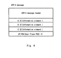
Fig. 4 is a block diagram of a GTP-C message according to the first exemplary embodiment. -
Fig. 5 is a diagram illustrating a flow of an ATTACH process according to the first exemplary embodiment. -
Fig. 6 is a diagram illustrating a flow of a process when performing TAU according to the first exemplary embodiment. -
Fig. 7 is a diagram illustrating a flow of a process when transmitting a small amount of data from UE according to the first exemplary embodiment. -
Fig. 8 is a diagram illustrating a flow of a handover process according to the first exemplary embodiment. -
Fig. 9 is a diagram illustrating a flow of a handover process according to the first exemplary embodiment. -
Fig. 10 is a diagram illustrating a flow of a process when receiving a small amount of data by PGW according to the first exemplary embodiment. -
Fig. 11 is a diagram illustrating a flow of a process when transmitting a small amount of data from UE according to the first exemplary embodiment. -
Fig. 12 is a diagram illustrating a flow of a process when transmitting a large amount of data according to the first exemplary embodiment. -
Fig. 13 is a diagram illustrating a flow of a process when transmitting a large amount of data according to the first exemplary embodiment. -
Fig. 14 is a diagram illustrating a flow of a process when deleting a dedicated bearer according to the first exemplary embodiment. -
Fig. 15 is a diagram illustrating a flow of a process when deleting a dedicated bearer according to the first exemplary embodiment. -
Fig. 16 is a diagram illustrating a flow of an ATTACH process according to a second exemplary embodiment. -
Fig. 17 is a diagram illustrating a flow of an ATTACH process according to the second exemplary embodiment. -
Fig. 18 is a diagram illustrating a flow of a process when performing TAU according to the second exemplary embodiment. -
Fig. 19 is a diagram illustrating a flow of a handover process according to the second exemplary embodiment. -
Fig. 20 is a block diagram of a mobile communication system according to a third exemplary embodiment. -
Fig. 21 is a block diagram of a mobile communication system according to the third exemplary embodiment. -
Fig. 22 is a block diagram of a mobile communication system according to the third exemplary embodiment. -
Fig. 23 is a block diagram of a RANAP message according to the third exemplary embodiment. -
Fig. 24 is a diagram illustrating a flow of an ATTACH process according to the third exemplary embodiment. -
Fig. 25 is a diagram illustrating a flow of a process when transmitting a small amount of data from UE according to the third exemplary embodiment. -
Fig. 26 is a diagram illustrating a flow of a process when performing RAU according to the third exemplary embodiment. -
Fig. 27 is a diagram illustrating a flow of a process when RNC and SGSN are changed according to the third exemplary embodiment. -
Fig. 28 is a diagram illustrating a flow of a process when RNC and SGSN are changed according to the third exemplary embodiment. -
Fig. 29 is a diagram illustrating a flow of a process when receiving a small amount of data by GGSN according to the third exemplary embodiment. -
Fig. 30 is a diagram illustrating a flow of a process when transmitting a small amount of data from UE according to the third exemplary embodiment. -
Fig. 31 is a diagram illustrating a flow of a process when transmitting and receiving a large amount of data according to the third exemplary embodiment. -
Fig. 32 is a diagram illustrating a flow of a process when transmitting and receiving a large amount of data according to the third exemplary embodiment. -
Fig. 33 is a diagram illustrating a flow of a process when deleting a dedicated bearer according to the third exemplary embodiment. -
Fig. 34 is a diagram illustrating a flow of a process when deleting a dedicated bearer according to the third exemplary embodiment. -
Fig. 35 is a diagram illustrating a flow of an ATTACH process according to a fourth exemplary embodiment. -
Fig. 36 is a diagram illustrating a flow of a process when performing RAU according to the fourth exemplary embodiment. -
Fig. 37 is a diagram illustrating a flow of a process when transmitting a small amount of data from UE according to the fourth exemplary embodiment. -
Fig. 38 is a diagram illustrating a flow of a handover process according to the fourth exemplary embodiment. -
Fig. 39 is a diagram illustrating a flow of a handover process according to the fourth exemplary embodiment. -
Fig. 40 is a diagram illustrating a flow of a process when receiving a small amount of data by GGSN according to the fourth exemplary embodiment. -
Fig. 41 is a diagram illustrating a flow of a process when transmitting a small amount of data from UE according to the fourth exemplary embodiment. -
Fig. 42 is a diagram illustrating a flow of a process when transmitting and receiving a large amount of data according to the fourth exemplary embodiment. -
Fig. 43 is a diagram illustrating a flow of a process when transmitting and receiving a large amount of data according to the fourth exemplary embodiment. -
Fig. 44 is a diagram illustrating a flow of a process when deleting a dedicated bearer according to the fourth exemplary embodiment. -
Fig. 45 is a diagram illustrating a flow of a process when deleting a dedicated bearer according to the fourth exemplary embodiment. - Exemplary embodiments of the present invention are described hereinafter with reference to the drawings. Firstly, a configuration example of a mobile communication system according to a first exemplary embodiment of the invention is described hereinafter with reference to
Fig 1 . The configuration of the mobile communication system shown inFig. 1 is an example of using LTE (Long Term Evolution) specified in the 3GPP for an access network. The mobile communication system shown inFig. 1 includes UE (User Equipment) 10, eNodeB (enhancedNode B) 20, MME (Mobility Management Entity) 30, SGW (Serving Gateway) 40 and PGW (Packet Data Network Gateway) 50. - The
UE 10 is communication equipment or a mobile station that performs wireless communication, and it may be a mobile phone or a smartphone terminal, for example. Further, theUE 10 may be an MTC device (machine-type-communication device). TheeNodeB 20 is a base station that performs wireless communication with a base station. TheUE 10 and theeNodeB 20 perform wireless communication using LTE, which is the wireless communication standard specified in the 3GPP. - The
SGW 40 is used as a data relay device that transmits and receives user data between theeNodeB 20 and thePGW 50. The user data is packet data including voice data or the like that is transmitted from theUE 10. - The
PGW 50 is used as a gateway device that transmits and receives user data with an external network. The external network is a network different from the network that includes the eNodeB20, the MME30, the SGW40 and the PGW50. The external network is a network that is managed by a mobile operator different from the mobile operator that manages the eNodeB20, the MME30, the SGW40 and the PGW50, for example. However, the external network is not limited thereto, and when the mobile operator is the same, it may be the same network as the network that includes the eNodeB20, the MME30, the SGW40 and the PGW50. - The
MME 30 is a device that performs a call control process. For example, theMME 30 designates SGW which is the destination of user data transmitted from theeNodeB 20 and notifies the designated SGW to theeNodeB 20. TheMME 30 transmits and receives a control signal to and from theeNodeB 20 and also transmits and receives a control signal to and from theSGW 40. - Protocols that are specified between the respective node devices are described hereinbelow. The control signal between the
UE 10 and theeNodeB 20 is transmitted and received using the protocol specified as RRC (Radio Resource Control). The user data in theUE 10 and theeNodeB 20 is transmitted and received using Traffic channel. - The user data between the
eNodeB 20 and theSGW 40 and the user data between theSGW 40 and thePGW 50 are transmitted and received using the protocol specified as GTP-U. - The control signal between the
eNodeB 20 and theMME 30 is transmitted and received using the protocol specified as SLAP (S1 Application Protocol). The control signal between theMME 30 and theSGW 40 and the control signal between theSGW 40 and thePGW 50 are transmitted and received using the protocol specified as GTP-C. - A configuration of transmitting and receiving a small amount of data between the
SGW 40 and thePGW 50 by using communication resources for transmitting and receiving a control signal is described hereinafter with reference toFig. 2 . The small amount of data is data that is transmitted from the MTC device, for example. Specific examples include measurement values of a sensor and a meter, sales of an automatic vending machine and the like. Further, the small amount of data may be user data that is autonomously transmitted and received between communication equipment without user operation. The small amount of data is specified as Small Data in the 3GPP (3GPP TS 22.368 V11.5.0 "Service requirements for Machine-Type Communications (MTC)", clause 7.2.5, 2012-06 etc.). The communication equipment is an automatic vending machine, a sensor terminal or the like, for example. The communication between the communication equipments is specified as MTC (Machine Type Communication) in the 3GPP. In other words, the small amount of data is data that is transmitted between MTC devices or between an MTC device and a server device or the like. In general, the MTC indicates communication that is autonomously performed without user operation. The communication resources are parameters that are set for transmitting and receiving user data or a control signal, resources necessary for transmitting and receiving user data or a control signal on a memory that stores parameters or a communication channel or the like, for example. -
Fig. 2 shows transmitting and receiving a small amount of data between theSGW 40 and thePGW 50 by using the protocol specified as GTP-C. For example, theSGW 40 transmits a small amount of data from theUE 10 that is transmitted from theeNodeB 20 through GTP-U to thePGW 50 through GTP-C. On the other hand, when thePGW 50 receives a small amount of data addressed to theUE 10, thePGW 50 transmits the small amount of data to theSGW 40 through GTP-C. In this manner, by transmitting and receiving a small amount of data between theSGW 40 and thePGW 50 by using GTP-C, it is not necessary to reserve communication resources for user data (for example, GTP-U) in theSGW 40 and thePGW 50 and thereby reduce resource load. -
Fig. 3 shows an example of transmitting a small amount of data, which has been transmitted using GTP-U, between theeNodeB 20 and theSGW 40 by using the protocol for transmitting and receiving a control signal. TheeNodeB 20 transmits a small amount of data that is transmitted through Traffic channel to theMME 30 through S1 AP. Further, theMME 30 transmits a small amount of data that is transmitted from theeNodeB 20 to theSGW 40 through GTP-C. On the other hand, when theSGW 40 receives a small amount of data addressed to theUE 10 from thePGW 50, theSGW 40 transmits the small amount of data to theMME 30 through GTP-C. Further, theMME 30 transmits the received small amount of data to theeNodeB 20 through S1 AP. Transmitting and receiving between theSGW 40 and thePGW 50 are the same as shown inFig. 2 and not redundantly described in detail. - A configuration example of a GTP-C message is described hereinafter with reference to
Fig. 4 . A GTP-C message that is transmitted through GTP-C includes a GTP-C message header and IE (Information Element) A to C. Further, in the GTP-C message, UP-PDU (User Plane-Protocol Date Unit) IE is specified in order to transmit a small amount of data. Further, in a S1 AP message that is used between the eNodeB 20 to theMME 30 also, UP-PDU IE is specified just like in the GTP-C message. - In this manner, by transmitting and receiving a small amount of data between the eNodeB 20 to the
SGW 40, in addition to between theSGW 40 and thePGW 50, using S1 AP and GTP-C that are used for transmitting a control signal, it is not necessary to reserve communication resources for user data in theeNodeB 20 and thereby reduce resource load. - Further, in the configuration of
Fig. 2 , the processing operation of theUE 10 and theeNodeB 20 is the same as that of theUE 10 and theeNodeB 20 shown inFig. 1 . Therefore, it is not necessary to incorporate a novel feature into theUE 10 and theeNodeB 20 in order to implement the present invention. On the other hand, in the configuration ofFig. 3 , the processing operation of theUE 10 is the same as that of theUE 10 shown inFig. 1 . Therefore, it is not necessary to incorporate a novel feature into theUE 10 in order to implement the present invention. The novel feature is a feature that receives a small amount of data transmitted through a user data bearer and transmitting the received small amount of data through a control signal bearer, for example. - A flow of a process (ATTACH) for UE location registration is described hereinafter with reference to
Fig. 5 . ATTACH is performed when power is supplied to the UE, for example, for registering the location of the UE in the mobile communication network. Further, inFig. 5 , eNodeB is denoted as eNB. In the following description, eNodeB and eNB are the same device. - First, the
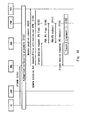
UE 10 transmits an ATTACH signal to the MME 30 (S1). Next, authentication and security setting are performed between theUE 10 and HSS (Home Subscriber Server) (S2). Then, theMME 30 transmits an Update Location request signal to the HSS (S3). Then, the HSS transmits an Update Location Ack signal to theMME 30. The Update Location Ack signal contains pseudo-U/Size attribution that is set per APN. The pseudo-U/Size attribution may be set per IMSI, IMEISV or the like, other than per APN. The HSS manages pseudo-U/Size attribution as subscriber data that is associated with theUE 10. Thus, the HSS can add pseudo-U/Size attribution to the Update Location Ack signal, which is an acknowledgement signal to the Update Location request signal transmitted from theUE 10. - The pseudo-U/Size attribution is used for setting a pseudo-U bearer. The pseudo-U bearer is a GTP-U bearer that is set in a pseudo or virtual manner. The bearer is a communication channel between devices. The bearer may be communication resources that is reserved for setting a communication channel between devices. Because the pseudo-U bearer is a bearer that is set in a pseudo or virtual manner, communication resources is not reserved or a minimum necessary communication resource is reserved. Specifically, when the
UE 10 performs the ATTACH process, reservation of communication resources is performed generally in order to set a GTP-U bearer. Instead of setting the GTP-U bearer, by setting the pseudo-U bearer for which reservation of communication resources is not actually performed, it is possible to avoid useless reservation of communication resources without changing the processing sequence between devices. To be specific, when transmitting a small amount of data through the GTP-C bearer, setting of the pseudo-U bearer is performed instead of setting of the GTP-U bearer, which is generally performed. In this manner, it is possible to accommodate communication equipment that transmits a small amount of data into a mobile communication system without allocating communication resources for setting a GTP-U bearer to the communication equipment. - Further, in the pseudo-U/Size attribution, information about a size that is defined as a small amount of data is specified as well. Data that is larger than the defined size is not treated as a small amount of data. Thus, data that is smaller than the defined size is treated as a small amount of data.
- The
MME 30 that has received the pseudo-U/Size attribution transmits a Create Session request signal containing PU (pseudo-U) flag to theSGW 40. Further, theSGW 40 transmits the Create Session request signal containing PU (pseudo-U) flag to the PGW 50 (S5). The PU flag is a parameter that notifies setting of a pseudo-U bearer, not a general GTP-U bearer, between theSGW 40 and thePGW 50. Further, the PU flag may be a parameter that notifies setting of a pseudo-U bearer, not a general GTP-U bearer, between theeNodeB 20 and theSGW 40. - Then, the
PGW 50 transmits a Create Session response signal containingPU status 1 to theSGW 40. Further, theSGW 40 transmits the Create Session response signal containingPU status 1 to the MME 30 (S6). ThePU status 1 is a parameter that indicates the status where the pseudo-U bearer is set between theSGW 40 and thePGW 50. The Create Session response signal is transmitted from thePGW 50 to theSGW 40 and further from theSGW 40 to theMME 30, and then thePU status 1 is stored in theSGW 40, and thereby setting of the pseudo-U bearer (which is referred to hereinafter as Pseudo-U treatment (1)) between theSGW 40 and thePGW 50 is done (S7). - Then, the
MME 30 transmits an Initial Context Setup Request/Attach Accept signal containing PU flag to the eNodeB 20 (S8). TheMME 30 thereby notifies setting of a pseudo-U bearer, not a GTP-U bearer, between theeNodeB 20 and theSGW 40. Then, theeNodeB 20 transmits a RRC Connection Reconfiguration signal to the UE 10 (S9). TheUE 10 then transmits a RRC Connection Reconfiguration Complete signal to the eNodeB 20 (S10). - Then, the
eNodeB 20 transmits an Initial Context Setup Response signal containingPU status 2 to the MME 30 (S11). ThePU status 2 is a parameter that indicates the status where the pseudo-U bearer is set between theeNodeB 20 and theSGW 40. Setting of the pseudo-U bearer (which is referred to hereinafter as Pseudo-U treatment (2)) between theeNodeB 20 and theSGW 40 is thereby done (S12). - Then, the
MME 30 transmits a Modify bearer request signal containing PU flag andPU status 2 to the SGW 40 (S13). TheMME 30 thereby notifies the status of Pseudo-U treatment (2) to theSGW 40. TheSGW 40 then transmits a Modify bearer response signal to the MME 30 (S14). - The
SGW 40stores PU status 1 andPU status 2. Therefore, theSGW 40 can determine which bearer the received small amount of data is to be set to and transmitted. For example, it is assumed that theSGW 40stores PU status 2 indicating that the pseudo-U bearer is set between theeNodeB 20 and theSGW 40. In this state, when theSGW 40 receives a small amount of data from thePGW 50, it transmits the small amount of data to theMME 30 through the GTP-C bearer. For example, in the case where theSGW 40 does not storePU status 2, theSGW 40 transmits the small amount of data received from thePGW 50 to theeNodeB 20 through the GTP-U bearer. The case where theSGW 40 does not storePU status 2 occurs when theeNodeB 20 and theSGW 40 do not have the feature to set the pseudo-U bearer between theeNodeB 20 and theSGW 40, for example. - In the above description, the example of setting Pseudo-U treatment (1) and Pseudo-U treatment (2) is described. In other words, the example of transmitting a small amount of data from the
eNodeB 20 to thePGW 50 by using the bearer for transmitting a control signal is described. Note that, however, the procedure of setting Pseudo-U treatment (2) may be omitted for the case of transmitting a small amount of data only between theSGW 40 and thePGW 50 by using the bearer for transmitting a control signal. This is the same in the following description as well. - Hereinafter, a flow of a process in the case where TAU (Tracking Area Update) is performed is described with reference to
Fig. 6 . Tracking Area (TA) is location information of theUE 10 that is managed on the mobile communication network, such as a core network, for example. Tracking Area (TA) may be an area composed of a plurality of cells. TAU is processing that is performed when TA where theUE 10 is located is changed. - First, the
UE 10 transmits a TAU request signal to the new MME 30 (New MME) that is going to manage theUE 10 after TA is changed (S21). Next, the New MME transmits a Context Request signal to the MME 30 (Old MME) that has been managing theUE 10 before TA is changed (S22). Then, the Old MME transmits a Context Response signal to the New MME (S23). The Context Response signal contains PU flag. Thus, the Old MME notifies the New MME that the pseudo-U bearer, instead of GTP-U, is to be set for theUE 10. After that, authentication and security setting are performed between theUE 10 and HSS (Home Subscriber Server) (S24). The New MME then transmits a Context Request Ack signal to the Old MME (S25). - Then, the New MME transmits a Create Session request signal containing PU flag to the SGW 40 (New SGW) that is newly allocated to transmit a small amount of data transmitted from the
UE 10 after change in TA (S26). Then, the pseudo-U bearer that has been set between the SGW 40 (Old SGW) that has been allocated before change in TA and thePGW 50 is to be set between the New SGW and thePGW 50. To make this setting, the New SGW transmits a Modify bearer request signal containing PU flag to the PGW 50 (S27). Next, thePGW 50 transmits a Modify bearer response signal containingPU status 1 to the New SGW (S28). The New SGW then transmits a Create Session response signal containingPU status 1 to the New MME (S29). Pseudo-U treatment (1) is thereby set between the New SGW and the PGW 50 (S30). - Then, the New MME transmits an Update Location request signal to the HSS (S31). The HSS then transmits an Update Location Ack signal to the New MME. The Update Location Ack signal contains pseudo-U/Size attribution that is set per APN (S32). The pseudo-U/Size attribution may be set per IMSI, IMEISV or the like, other than per APN. Then, the New MME transmits a TAU accept signal to the UE 10 (S33).
- A flow of a process in the case of transmitting a small amount of data from the
UE 10 is described hereinafter with reference toFig. 7 . First, theUE 10 transmits a PDN Connectivity Request (APN) signal to the MME 30 (S41). Next, theMME 30 transmits an Initial Context Setup Request signal containing PU flag to the eNodeB 20 (S42). Processing of Steps S43 to S48 is the same as that of Steps S9 to S14 inFig. 5 and thus not redundantly described in detail. - A flow of a handover process is described hereinafter with reference to
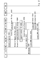
Figs. 8 and9 . In the handover shown inFigs. 8 and9 , the case where the eNodeB, the MME and the SGW to which theUE 10 belongs are changed is described. First, the eNodeB 20 (Old eNB) from which handover is made transmits a Handover required signal to the MME (Old MME) that manages the Old eNB (S51). Next, the Old MME transmits a Forward relocation request signal to the MME (New MME) that manages the eNodeB 20 (New eNB) to which handover is made (S52). The Forward relocation request signal contains PU flag. Then, the New MME transmits a Create Session request signal to the New SGW to be connected to the New eNB (S53). The Create Session request signal contains PU flag. Then, the New SGW transmits a Create Session response signal to the New MME (S54). - Then, the New MME transmits a Handover request signal containing PU flag to the New eNB (S55). The New eNB then transmits a Handover request ack signal containing
PU status 2 to the New MME (S56). Pseudo-U treatment (2) is thereby set between the New eNB and the New SGW (S57). Then, the New MME transmits a Forward relocation response signal to the Old MME (S58). The Old MME then transmits a Handover command signal to the Old eNB (S59). Then, the Old eNB transmits a Handover command signal to the UE 10 (S60). - A handover process after Step S60 is described hereinafter with reference to
Fig. 9 . After Step S60, theUE 10 transmits a Handover confirm signal to the New eNB (S61). Then, the New eNB transmits a Handover Notify signal to the New MME (S62). The New MME then transmits a Forward relocation complete Notification signal to the Old MME (S63). Then, the Old MME transmits a Forward relocation complete Ack signal to the New MME (S64). Then, the New MME transmits a Modify bearer request signal to the New SGW (S65). The Modify bearer request signal contains PU flag andPU status 2. - Then, the New SGW transmits a Modify bearer request signal containing PU flag to the PGW 50 (S66). Next, the
PGW 50 transmits a Modify bearer response signal containingPU status 1 to the New SGW (S67). Further, the New SGW transmits a Modify bearer response signal containingPU status 1 to the New MME (S68). Pseudo-U treatment (1) is thereby set between the New SGW and the PGW 50 (S69). - A flow of a process in the case where the
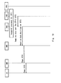
PGW 50 receives a small amount of data addressed to theUE 10 is described hereinafter with reference toFig. 10 . It is assumed that Pseudo-U treatment (1) is set between theSGW 40 and the PGW 50 (S71). When thePGW 50 receives a small amount of data addressed to theUE 10 that is associated with Pseudo-U treatment (1), it transmits the received small amount of data to theSGW 40 through GTP-C (S72). Next, theSGW 40 transmits a Downlink Data Notification signal to theMME 30 to notify that the small amount of data is received (S73). The Downlink Data Notification signal may contain a small amount of data. Then, theMME 30 transmits a Page signal to the eNodeB 20 (S74), and further theeNodeB 20 transmits the Page signal to the UE 10 (S75). Note that, in order to determine whether the received data is a small amount of data or not, thePGW 50 may determine whether the size of the data exceeds the size that is defined as a small amount of data. - A flow of a process in the case of transmitting a small amount of data from the
UE 10 is described hereinafter with reference toFig. 11 . Note that the process shown inFig. 11 is used also as the process which is executed by theUE 10 that has received the Page signal inFig. 10 . - First, the
UE 10 transmits a Service Request signal to the MME 30 (S76). Next, authentication and security setting are performed between theUE 10 and HSS (Home Subscriber Server) (S77). Then, theMME 30 transmits a S1-AP:Initial Context Setup Request signal containing PU flag to the eNodeB 20 (S78). The S1-AP:Initial Context Setup Request signal may contain a small amount of data. Then, theeNodeB 20 sets a radio bearer with the UE 10 (S79). TheeNodeB 20 may transmit the small amount of data received with the S1-AP:Initial Context Setup Request signal to theUE 10 by using the set radio bearer. Then, theeNodeB 20 transmits a S1-AP:Initial Context Setup Complete signal containingPU status 2 to the MME 30 (S80). Pseudo-U treatment (2) is thereby set between theeNodeB 20 and the SGW 40 (S81). - Then, the
MME 30 transmits a Modify bearer request signal containing PU flag and PU status 2 (S82). TheSGW 40 then transmits a Modify bearer response signal to the MME 30 (S83). - The case of transmitting and receiving a large amount of data that is larger than the data size (or the amount of data) defined as a small amount of data in the environment of transmitting and receiving a small amount of data using GTP-C is described hereinafter with reference to
Fig. 12 . For example, in the case where a temperature sensor is used as communication equipment that is used for the MTC, the temperature sensor notifies temperature information to a server device or the like at regular time intervals. The temperature information in this case is treated as a small amount of data. On the other hand, when a request for software update of the temperature sensor is made, the temperature sensor transmits data (which is referred to hereinafter as a large amount of data) that is larger than the small amount of data in some cases. A method of transmitting the large amount of data in such a case is described hereinbelow. The large amount of data is data that is larger than the data size defined in pseudo-U/Size attribution. - In the case where the GTP-C bearer is set between the
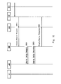
SGW 40 and thePGW 50 in order to transmit a small amount of data, when a large amount of data addressed to theUE 10 arrives at thePGW 50, thePGW 50 newly sets a dedicated bearer for transmitting a large amount of data with theSGW 40. The dedicated bearer may be a GTP-U bearer, for example. To make this setting, thePGW 50 transmits a Create Bearer Request signal to theSGW 40. Further, theSGW 40 transmits the Create Bearer Request signal to the MME 30 (S91). Then, theMME 30 transmits a Bearer Setup Request signal to the eNodeB 20 (S92). TheeNodeB 20 then transmits a Bearer Setup Response signal to the MME 30 (S93). TheMME 30 then transmits a Create Bearer Response signal to theSGW 40. TheSGW 40 then transmits the Create Bearer Response signal to the PGW 50 (S94). - In this manner, by transmitting the Create Bearer Request/Response signal, a dedicated bearer for transmitting a large amount of data is set between the
SGW 40 and thePGW 50, and by transmitting the Bearer Setup Request/Response signal, a dedicated bearer is set also between theeNodeB 20 and theSGW 40. - Further, in the case where GTP-C is set between the
SGW 40 and thePGW 50 in order to transmit a small amount of data, when a large amount of data arrives at thePGW 50, thePGW 50 may change the pseudo-U bearer that is already set between theSGW 40 and thePGW 50 to a general GTP-U bearer or a dedicated bearer. In this case, an Update Bearer Request/Response signal is used instead of the Create Bearer Request/Response signal in Steps S91 and S94 inFig. 12 . Further, a Bearer Modify Request/Response is used instead of the Bearer Setup Request/Response signal in Steps S92 and S93 inFig 12 . - Further, the Bearer Modify Request/Response signal is transmitted only when Pseudo-U treatment(2) is set between the
eNodeB 20 and theSGW 40. - The case of transmitting a large amount of data from the
UE 10 in the environment of transmitting and receiving a small amount of data using GTP-C and S1-AP is described hereinafter with reference toFig. 13 . - In the case where S1-AP is set between the
eNodeB 20 and theMME 30 and GTP-C is set between theMME 30 and thePGW 50 for transmitting a small amount of data, a dedicated bearer for transmitting a large amount of data is newly set between theeNodeB 20 and thePGW 50 in order to transmit a large amount of data from theUE 10. - First, when the
eNodeB 20 receives a large amount of data from theUE 10, theeNodeB 20 transmits a Bearer Resource Command signal to the MME 30 (S111). TheMME 30 then transmits the Bearer Resource Command signal to theSGW 40, and further theSGW 40 transmits the Bearer Resource Command signal to the PGW 50 (S112). Then, thePGW 50 transmits a Create Bearer Request signal to theSGW 40, and further theSGW 40 transmits the Create Bearer Request signal to the MME 30 (S113). - Then, the
MME 30 transmits a Bearer Setup Request signal to the eNodeB 20 (S114). TheeNodeB 20 then transmits a Bearer Setup Response to the MME 30 (S115). TheMME 30 then transmits a Create Bearer Response signal to the SGW 40 (S116). - In this manner, by transmitting the Create Bearer Request/Response signal between the
MME 30 and thePGW 50, a dedicated bearer for transmitting a large amount of data is set between theSGW 40 and thePGW 50, and by transmitting the Bearer Setup Request/Response signal between theMME 30 and theeNodeB 20, a dedicated bearer is set also between theeNodeB 20 and theSGW 40. - In the case of transmitting a small amount of data using the GTP-C bearer between the
SGW 40 and thePGW 50 and transmitting a small amount of data using the GTP-U bearer between theSGW 40 and theeNodeB 20, a large amount of data is transmitted through the GTP-U bearer from theUE 10 to theSGW 40. In such a case, a Bearer Resource Command signal is transmitted from theSGW 40 to thePGW 50. Further, a Create Bearer Request/Response signal is transmitted between thePGW 50 and theMME 30. A dedicated bearer that is used for transmitting a large amount of data is thereby set between theSGW 40 and thePGW 50. Further, in this case, the Bearer Setup Request/Response signal inFig. 13 is not transmitted. - Further, in the case where GTP-C is set between the
SGW 40 and thePGW 50 and between theMME 30 and theSGW 40 for transmitting a small amount of data, and S1 AP is set between theeNodeB 20 and theMME 30, when theeNodeB 20 receives a large amount of data from theUE 10, the pseudo-U bearer that is already set between theeNodeB 20 and thePGW 50 may be changed to a general GTP-U bearer or a dedicated bearer. In this case, a Modify Bearer Request signal is used instead of the Create Bearer Request/Response signal in Steps S113 and S116 inFig. 13 . Further, a Bearer Modify Request/Response signal is used instead of the Bearer Setup Request/Response signal in Steps S114 and S115 inFig 13 . - Further, the Bearer Modify Request/Response signal is transmitted only when Pseudo-U treatment (2) is set between the
eNodeB 20 and theSGW 40. - In the case of transmitting a small amount of data using the GTP-C bearer between the
SGW 40 and thePGW 50 and transmitting a small amount of data using the GTP-U bearer between theSGW 40 and theeNodeB 20, a large amount of data is transmitted through the GTP-U bearer from theUE 10 to theSGW 40. In such a case, a Bearer Resource Command signal is transmitted from theSGW 40 to thePGW 50. Further, a Modify Bearer Request/Response signal is transmitted between thePGW 50 and theMME 30. The pseudo-U bearer that is already set between theSGW 40 and thePGW 50 can be thereby changed to a dedicated bearer or a GTP-U bearer that is used for transmitting a large amount of data. Further, in this case, the Bearer Modify Request/Response signal inFig. 13 is not transmitted. - A flow of a process in the case of deleting a dedicated bearer that is set for transmitting a large amount of data is described hereinafter with reference to
Fig. 14 . The dedicated bearer is deleted when transmission of a large amount of data ends between theeNodeB 20 and thePGW 50. To be specific, the dedicated bearer may be deleted when the fact that a large amount of data is not transmitted for a certain period of time is detected in theeNodeB 20 or thePGW 50. - First, when the
PGW 50 detects the fact that a large amount of data is not transmitted for a certain period of time, it transmits a Delete Bearer Request signal to theSGW 40, and further theSGW 40 transmits the Delete Bearer Request signal to the MME 30 (S131). Then, in order to delete the dedicated bearer that is set between theeNodeB 20 and theSGW 40, theMME 30 transmits a Deactivate Bearer Request signal to the eNodeB 20 (S132). - Next, the
eNodeB 20 transmits a Deactivate Bearer Response signal to the MME 30 (S133). TheMME 30 then transmits a Delete Bearer Response signal to theSGW 40, and further theSGW 40 transmits the Delete Bearer Response signal to the PGW 50 (S134). The dedicated bearer that is set between theeNodeB 20 and thePGW 50 is thereby deleted. - Further, in the case where the pseudo-U bearer has been changed to the GTP-U bearer or the dedicated bearer in order to transmit a large amount of data, a flow of a process of setting the bearer back to the pseudo-U bearer at the end of transmission of a large amount of data is described hereinafter. To be specific, an Update Bearer Request/Response signal is used instead of the Delete Bearer Request/Response signal in Steps S131 and S134 in
Fig. 14 . Further, a Bearer Modify Request/Response signal is used instead of the Deactivate Bearer Request/Response signal in Steps S132 and S133 inFig. 14 . Using those signals, the process of setting the GTP-U bearer or the dedicated bearer back to the pseudo-U bearer is performed. - A flow of a process in the case of deleting a dedicated bearer when the
eNodeB 20 detects the fact that a large amount of data is not transmitted for a certain period of time is described hereinafter with reference toFig. 15 . First, when theeNodeB 20 detects the fact that transmission of a large amount of data is not performed for a certain period of time, it transmits a Bearer Resource Command signal to the MME 30 (S141). - Then, the
MME 30 transmits a Delete Bearer Command signal to theSGW 40, and further theSGW 40 transmits the Delete Bearer Command signal to the PGW 50 (S142). Then, thePGW 50 transmits a Delete Bearer Request signal to theSGW 40, and further theSGW 40 transmits the Delete Bearer Request signal to the MME 30 (S143). Then, theMME 30 transmits a Deactivate Bearer Request signal to the eNodeB 20 (S144). Then, theeNodeB 20 transmits a Deactivate Bearer Response signal to the MME 30 (S145). TheMME 30 then transmits a Delete Bearer Response signal to theSGW 40, and further theSGW 40 transmits the Delete Bearer Response signal to the PGW 50 (S146). - In this manner, by transmitting the Delete Bearer Request/Response signal, the dedicated bearer for transmitting a large amount of data between the
SGW 40 and thePGW 50 is deleted, and by transmitting the Deactivate Bearer Request/Response signal, the dedicated bearer between theeNodeB 20 and theSGW 40 is deleted. - Further, in the case where the pseudo-U bearer has been changed to the GTP-U bearer or the dedicated bearer in order to transmit a large amount of data, a flow of a process of setting the bearer back to the pseudo-U bearer at the end of transmission of a large amount of data is described hereinafter. To be specific, a Modify Bearer Request/Response signal is used instead of the Delete Bearer Request/Response signal in Steps S143 and S146 in
Fig. 15 . Further, a Bearer Modify Request/Response signal is used instead of the Deactivate Bearer Request/Response signal in Steps S144 and S145 inFig. 15 . Using those signals, the process of setting the GTP-U bearer or the dedicated bearer back to the pseudo-U bearer is performed. - In the case of transmitting a small amount of data using the GTP-C bearer between the
SGW 40 and thePGW 50 and transmitting a small amount of data using the GTP-U bearer between theSGW 40 and theeNodeB 20, the fact that a large amount of data is not transmitted may be detected in theSGW 40. In this case, a Delete Bearer Command signal is transmitted from theSGW 40 to thePGW 50. Further, a Delete Bearer Request/Response signal is transmitted between thePGW 50 and theMME 30. The dedicated bearer that is set between theSGW 40 and thePGW 50 to be used for transmitting a large amount of data is thereby deleted. Further, in this case, the Deactivate Bearer Request/Response inFig. 15 is not transmitted. - As described above, by using the mobile communication system according to the first exemplary embodiment of the invention, it is possible to set the pseudo-U bearer that does not require reservation of communication resources between the
eNodeB 20 and thePGW 50. It is thereby possible to transmit a small amount of data by using communication resources that are used for transmitting a control signal such as GTP-C and S1-AP, in the same process flow as in the case of using the GTP-U bearer for transmission of a small amount of data. - An example in which transfer of a control signal and user data between the
SGW 40 and thePGW 50 is performed using a transfer method that is specified as PMIP (Proxy Mobile IP) according to a second exemplary embodiment of the invention is described hereinbelow. The control signal between theSGW 40 and thePGW 50 is transmitted and received by using the protocol that is specified in PMIP (which is referred to hereinafter as PMIP). The user data between theSGW 40 and thePGW 50 is transferred as a general IP packet. - In the case where PMIP is used between the
SGW 40 and thePGW 50, a PMIP bearer is used instead of the GTP-C bearer between theSGW 40 and thePGW 50 inFig. 2 for transmission of a small amount of data. - Further, in a PMIP message that is transmitted through PMIP, a PMIP message header is used instead of the GTP-C message header in
Fig. 4 , and it has IE A to C just like shown inFig. 4 . Further, in the PMIP message, UP-PDU IE is specified to transmit a small amount of data. - A flow of an ATTACH process of the
UE 10 in the case where PMIP is used between theSGW 40 and thePGW 50 is described hereinafter with reference toFigs. 16 and17 . Steps S151 to S154 are the same as Steps S1 to S4 inFig. 5 and thus not redundantly described in detail. In Step S154, when theMME 30 receives an Update Location Ack signal, it transmits a Create Session request signal containing PU flag to the SGW 40 (S155). - Next, the
SGW 40 transmits a PBU (Proxy Binding Update) signal to the PGW 50 (S156). The PBU signal contains PU flag. Then, thePGW 50 transmits a PBA (Proxy Binding Ack) signal (S157). The PBA signal containsPU status 1. Then, theSGW 40 transmits a Create Session response signal to the MME 30 (S158). The Create Session response signal containsPU status 1. Pseudo-U treatment (1) is thereby set between theSGW 40 and the PGW 50 (S159). Steps S160 to S166 inFig. 17 are the same as Steps S8 to S14 inFig. 5 and thus not redundantly described in detail. - A flow of a process of TAU (Tracking Area Update) in the case where PMIP is used between the
SGW 40 and thePGW 50 is described hereinafter with reference toFig. 18 . Steps S171 to S176 are the same as Steps S21 to S26 inFig. 6 and thus not redundantly described in detail. In Step S 176, the New SGW that has received a Create Session request signal transmits a PBU signal containing PU flag to the PGW 50 (S177). Next, thePGW 50 transmits a PBA signal containingPU status 1 to the New SGW (S178). Steps S179 to S183 are the same as Steps S29 to S33 inFig. 6 and thus not redundantly described in detail. - A flow of a handover process after Handover command is transmitted to the
UE 10 is described hereinafter with reference toFig. 19 . Steps S191 to S195 are the same as Steps S61 to S65 inFig. 9 and thus not redundantly described in detail. In Step S195, the New SGW that has received a Modify bearer request signal transmits a PBU signal containing PU flag to the PGW 50 (S196). ThePGW 50 then transmits a PBA signal containingPU status 1 to the New SGW (S197). Steps S198 and S199 are the same as Steps S68 and S69 inFig. 9 and thus not redundantly described in detail. - As described above, by using the mobile communication system according to the second exemplary embodiment of the invention, it is possible to set the pseudo-U bearer that does not require reservation of communication resources between the
eNodeB 20 and thePGW 50 also in the case of using the transfer method that is specified as PMIP between theSGW 40 and thePGW 50. It is thereby possible to transmit a small amount of data by using communication resources that are used for transmitting a control signal such as PMIP, in the same process flow as in the case of using the GTP-U bearer for transmission of a small amount of data. - A configuration example of a mobile communication system according to a third exemplary embodiment of the invention is described hereinafter with reference to
Fig. 20 . The configuration of the mobile communication system shown inFig. 20 is an example of using GPRS that is specified as the second generation or the third generation specified in the 3GPP for a core network. Devices that constitute GPRS includeSGSN 45 andGGSN 55. Further,RNC 25 is used for an access network or RAN (Radio Area Network), and theUE 10 is connected to theRNC 25. - The
UE 10 is the same as that inFig. 1 and not redundantly described in detail. TheRNC 25 is a device that integrates base stations and performs communication with a UE (mobile station) through a base station. For example, theRNC 25 specifies theSGSN 45 that is a destination of user data transmitted from theUE 10 and transmits the user data to the specifiedSGSN 45. - The
SGSN 45 is used as a data relay device that transmits and receives user data between theRNC 25 and theGGSN 55. The user data is packet data containing voice data or the like transmitted from theUE 10. - The
GGSN 55 is used as a gateway device that transmits and receives user data with an external network. The external network is a different network from a network that has theRNC 25, theSGSN 45 and theGGSN 55. In some cases, the external network is a network that is managed by a mobile operator different from the mobile operator that manages theRNC 25, theSGSN 45 and theGGSN 55, for example. - Protocols that are specified between the respective node devices are described hereinafter with reference to
Fig. 20 . The control signal between theUE 10 and theRNC 25 is transmitted and received using the protocol defined as RRC. The user data in theUE 10 and theRNC 25 is transmitted and received using Traffic channel. - The user data between the
RNC 25 and theSGSN 45 and the user data between theSGSN 45 and theGGSN 55 are transmitted and received using the protocol specified as GTP-U. - The control signal between the
RNC 25 and theSGSN 45 is transmitted and received using the protocol specified as RANAP. The control signal between theSGSN 45 and theGGSN 55 is transmitted and received using the protocol specified as GTP-C. - A configuration of transmitting and receiving a small amount of data between the
SGSN 45 and theGGSN 55 by using communication resources for transmitting and receiving a control signal is described hereinafter with reference toFig. 21 . -
Fig. 21 shows transmitting and receiving a small amount of data between theSGSN 45 and theGGSN 55 by using the protocol specified as GTP-C. For example, theSGSN 45 transmits a small amount of data that is transmitted from theRNC 25 through GTP-U to theGGSN 55 through GTP-C. Alternatively, when theGGSN 55 receives a small amount of data addressed to theUE 10, theGGSN 55 transmits the small amount of data to theSGSN 45 through GTP-C. In this manner, by transmitting and receiving a small amount of data between theSGSN 45 and theGGSN 55 by using GTP-C, it is not necessary to reserve communication resources for user data in theSGSN 45 and theGGSN 55 and thereby reduce resource load. -
Fig. 22 shows an example of transmitting a small amount of data, which has been transmitted using GTP-U, between theRNC 25 and theSGSN 45 by using the protocol for transmitting and receiving a control signal. TheRNC 25 transmits a small amount of data that is transmitted through Traffic channel to theSGSN 45 through RANAP. Alternatively, when theSGSN 45 receives a small amount of data addressed to theUE 10 from theGGSN 55, theSGSN 45 transmits the small amount of data to theRNC 25 through RANAP. Transmitting and receiving between theSGSN 45 and theGGSN 55 are the same as shown inFig. 21 and not redundantly described in detail. - In this manner, by transmitting and receiving a small amount of data between the
RNC 25 to theSGSN 45, in addition to between theSGSN 45 and theGGSN 55, by using RANAP that is used for transmitting a control signal, it is not necessary to reserve communication resources for user data in theRNC 25 and thereby reduce resource load. - A configuration example of RANAP is described hereinafter with reference to
Fig. 23 . A RANAP message that is transmitted through RANAP has a RANAP message header and IE A to C. Further, in the RANAP message, UP-PDU IE is specified to transmit a small amount of data. - Further, in the configuration of
Fig. 21 , the processing operation of theUE 10 and theRNC 25 is the same as that of theUE 10 and theRNC 25 shown inFig. 20 . Therefore, it is not necessary to incorporate a novel feature into theUE 10 and theRNC 25 in order to implement the present invention. On the other hand, in the configuration ofFig. 22 , the processing operation of theUE 10 is the same as that of theUE 10 shown inFig. 20 . Therefore, it is not necessary to incorporate a novel feature into theUE 10 in order to implement the present invention. - A flow of an ATTACH process in the network according to the second exemplary embodiment of the invention is described hereinafter with reference to
Fig. 24 . First, theUE 10 transmits an ATTACH signal to the SGSN 45 (S201). Next, authentication and security setting are performed between theUE 10 and HSS (Home Subscriber Server) (S202). Then, theSGSN 45 transmits an Update Location request signal to the HSS (S203). Then, the HSS transmits an Insert subscriber data signal to the SGSN 45 (S204). The Insert subscriber data signal contains pseudo-U/Size attribution that is set per APN. The pseudo-U/Size attribution may be set per IMSI, IMEISV or the like, other than per APN. - Then, the
SGSN 45 transmits an Insert subscriber data Ack signal to the HSS (S205). The HSS then transmits an Update Location ACK signal to theSGSN 45. TheSGSN 45 thereby acquires and manages pseudo-U attribution information that is set per APN or the like. Then, theSGSN 45 transmits an ATTACH accept signal to the UE 10 (S207). - A flow of a PDP Context Activation process is described hereinafter with reference to
Fig. 25 . PDP Context is communication resources that are used for transmitting user data between theSGSN 45 and theGGSN 55. Further, an example in which a small amount of data is transmitted as user data is described in this figure. - First, the
UE 10 transmits an Activate PDP Context Request (APN) signal to the SGSN 45 (S211). TheSGSN 45 then transmits a Create PDP Context Request signal containing PU flag to the GGSN 55 (S212). Then, theGGSN 55 transmits a Create PDP Context Response signal containingPU status 1 to the SGSN 45 (S213). In this manner, by sharingPU status 1 between theSGSN 45 and theGGSN 55, Pseudo-U treatment (1) is set between theSGSN 45 and the GGSN 55 (S214). - Next, in order to set a pseudo-U bearer between the
RNC 25 and theSGSN 45, theSGSN 45 transmits a RAB assignment Request signal containing PU flag to the RNC 25 (S215). TheRNC 25 then sets a Radio bearer with the UE 10 (S216). Then, theRNC 25 transmits a RAB assignment Response signal containingPU status 2 to the SGSN 45 (S217). In this manner, by sharingPU status 2 between theRNC 25 and theSGSN 45, Pseudo-U treatment (2) is set between theRNC 25 and the SGSN 45 (S218). Then, theSGSN 45 transmits an Activate PDP Context Accept signal to the UE 10 (S219). - A flow of a RAU (Routing Area Update) process that accompanies change in SGSN is described hereinafter with reference to
Fig. 26 . Routing Area (RA) is location information of theUE 10 that is managed on a GPRS network. RA may be an area composed of a plurality of cells. RAU is processing that is performed when RA where theUE 10 is located is changed. - First, the
UE 10 transmits a RAU signal to the SGSN (which is referred to hereinafter as New SGSN) that manages RA after change (S221). Next, the New SGSN transmits a SGSN Context request signal to the SGSN (which is referred to hereinafter as Old SGSN) that manages RA before change (S222). Then, the Old SGSN transmits a SGSN Context response signal to the New SGSN (S223). The SGSN Context response signal contains pseudo-U/Size attribution that is associated with theUE 10. After that, authentication and security setting are performed between theUE 10 and HSS (Home Subscriber Server) (S224). - Then, the New SGSN transmits a SGSN Context Ack signal to the Old SGSN (S225). The New SGSN then transmits an Update PDP Context Request signal to the
GGSN 55 in order to set a pseudo-U bearer with the GGSN 55 (S226). The Update PDP Context Request signal contains PU flag. Then, theGGSN 55 transmits an Update PDP Context Response signal containingPU status 1 to the New SGSN (S227). Pseudo-U treatment (1) is thereby set between the New SGSN and the GGSN 55 (S228). - Steps S229 to S232 are the same as Steps S203 to S206 in
Fig. 24 and thus not redundantly described in detail. In Step S232, the New SGSN that has received an Update Location Ack signal transmits a RAU accept signal to the UE 10(S233). - A flow of a process in the case where the RNC and the SGSN to which the
UE 10 is connected are changed is described hereinafter with reference toFigs. 27 and28 . - First, the RNC before change (which is referred to hereinafter Old RNC) transmits a Relocation Required signal to the SGSN before change (which is referred to hereinafter Old SGSN) (S241). Next, the Old SGSN transmits a Forward Relocation Request signal containing PU flag to the SGSN after change (which is referred to hereinafter New SGSN) (S242). Then, the New SGSN transmits a Relocation Request signal containing PU flag to the New RNC (S243). Then, the New RNC transmits a Relocation Request Acknowledge signal containing
PU status 2 to the New SGSN (S244). Pseudo-U treatment (2) is thereby set between the New RNC and the New SGSN (S245). - Then, the New SGSN transmits a Forward Relocation Response signal to the Old SGSN(S246). The Old SGSN then transmits a Relocation command signal to the Old RNC (S247). The Old RNC then transmits a RRC message signal to the UE 10(S248). Then, the Old RNC transmits a Forward SRNS Context signal to the Old SGSN (S249). The Old SGSN then transmits a Forward SRNS Context signal to the New SGSN (S250). The New SGSN transmits a Forward SRNS Context Ack signal to the Old SGSN (S251) and further transmits a Forward SRNS Context signal to the New RNC (S252).
- Referring then to
Fig. 28 , when theUE 10 is detected by the New RNC (S253), the New RNC transmits a Relocation detect signal to the New SGSN (S254). TheUE 10 then transmits a RRC message signal to the New RNC (S255). The New RNC then transmits a Relocation complete signal to the New SGSN (S256). The New SGSN then transmits a Forward relocation complete signal to the Old SGSN (S257). The Old SGSN then transmits a Forward relocation complete Ack signal to the New SGSN (S258). The New SGSN then transmits an Update PDP Context request signal containing PU flag to the GGSN 55 (S259). TheGGSN 55 then transmits an Update PDP Context Response signal containingPU status 1 to the New SGSN (S260). Pseudo-U treatment (1) is thereby set between the New SGSN and the GGSN 55 (S261). - Further, in order to release communication resources that are reserved between the Old SGSN and the Old RNC, the Old SGSN transmits an Iu release command signal to the Old RNC (S262). The Old RNC then transmits an Iu release command complete signal to the Old SGSN(S263).
- A flow of a process in the case where the
GGSN 55 receives a small amount of data addressed to theUE 10 is described hereinafter with reference toFig. 29 . - It is assumed that Pseudo-U treatment (1) is set between the
SGSN 45 and the GGSN 55 (S271). When theGGSN 55 receives a small amount of data addressed to theUE 10 that is associated with Pseudo-U treatment (1), it transmits the received small amount of data to theSGSN 45 through GTP-C (S272). Next, theSGSN 45 transmits a Page signal to the RNC 25 (S273), and further theRNC 25 transmits the Page signal to the UE 10 (S274). - A flow of a process in the case of transmitting a small amount of data from the
UE 10 is described hereinafter with reference toFig. 30 . Note that the process shown inFig. 30 is used also as the process which is executed by theUE 10 that has received the Page signal inFig. 29 . - First, the
UE 10 transmits a Service Request signal to the SGSN 45 (S275). Next, theSGSN 45 transmits a RAB assignment Request signal containing PU flag to the RNC 25 (S276). The RAB assignment Request signal may contain a small amount of data. Then, theRNC 25 sets a radio bearer with the UE 10 (S277). TheRNC 25 may transmit the small amount of data received with the RAB assignment Request signal to theUE 10 by using the set radio bearer. Then, theRNC 25 transmits a RAB assignment Response signal containingPU status 2 to the SGSN 45 (S278). Pseudo-U treatment (2) is thereby set between theRNC 25 and the SGSN 45 (S279). - The case of transmitting and receiving a large amount of data addressed to the
UE 10 in the environment of transmitting and receiving a small amount of data using GTP-C is described hereinafter with reference toFig. 31 . - In the case where GTP-C is set between the
SGSN 45 and theGGSN 55 in order to transmit a small amount of data, when a large amount of data addressed to theUE 10 arrives at theGGSN 55, theGGSN 55 newly sets a dedicated bearer (PDP Context) for transmitting a large amount of data with theSGSN 45. The dedicated bearer may be referred to as Secondary PDP Context if a pseudo bearer is Primary PDP Context. To set the dedicated bearer, theGGSN 55 transmits an Initiate PDP Context Activation Request signal to the SGSN 45 (S281). TheSGSN 45 then transmits a RAB assignment Request signal to the RNC 25 (S282). TheRNC 25 then transmits a RAB assignment Response signal to the SGSN 45 (S283). TheSGSN 45 then transmits a Create PDP context Request signal to the GGSN 55 (S284). TheGGSN 55 then transmits a Create PDP context Response signal to the SGSN 45 (S285). TheSGSN 45 then transmits an Initiate PDP Context Activation Response signal to the GGSN 55 (S286). - In this manner, by transmitting the Create PDP Context Request/Response signal, a dedicated bearer for transmitting a large amount of data is set between the
SGSN 45 and theGGSN 55, and by transmitting the RAB assignment Request/Response signal, a dedicated bearer is set also between theRNC 25 and theSGSN 45. After this process, theGGSN 55 can transmit the received large amount of data to theSGSN 45, and further theSGSN 45 can transmit the received large amount of data to theRNC 25, both by using the dedicated bearer. - Further, in the case where GTP-C is set between the
SGSN 45 and theGGSN 55 in order to transmit a small amount of data, when a large amount of data arrives at theGGSN 55, theGGSN 55 may change the pseudo-U bearer that is already set between theSGSN 45 and theGGSN 55 to a general GTP-U bearer or a dedicated bearer. In this case, an Update PDP Context Request/Response signal is used instead of the Initiate PDP Context Activation Request signal in Steps S281 and S286 inFig. 31 . Further, the processing of Steps S284 and S285 inFig. 31 is omitted in this case. - Further, the RAB assignment Request/Response signal is transmitted only when Pseudo-U treatment(2) is set between the
RNC 25 and theSGSN 45. - The case of transmitting a large amount of data from the
UE 10 in the environment of transmitting and receiving a small amount of data using GTP-C is described hereinafter with reference toFig. 32 . In the case where RANAP is set between theRNC 25 and theSGSN 45 and GTP-C is set between theSGSN 45 and theGGSN 55 for transmitting a small amount of data, a dedicated bearer for transmitting a large amount of data is newly set between theeNodeB 20 and thePGW 50 in order to transmit a large amount of data from theUE 10. - First, when the
RNC 25 receives a large amount of data from theUE 10, theRNC 25 transmits a RAB assignment Request signal to the SGSN 45 (S291). TheSGSN 45 then transmits the RAB assignment Request signal to the RNC 25 (S292). Then, theRNC 25 transmits a RAB assignment Response signal to the SGSN 45 (S293). TheSGSN 45 then transmits a Create PDP Context Request signal to the GGSN 55 (S294). TheGGSN 55 then transmits a Create PDP Context Response signal to the SGSN 45 (S295). - In this manner, by transmitting the Create PDP Context Request/Response signal, a dedicated bearer for transmitting a large amount of data is set between the
SGSN 45 and theGGSN 55, and by transmitting the RAB assignment Request/Response signal, a dedicated bearer is set also between theRNC 25 and theSGSN 45. After this process, theRNC 25 can transmit the received large amount of data to theSGSN 45, and further theSGSN 45 can transmit the received large amount of data to theGGSN 55, both by using the dedicated bearer. - In the case of transmitting a small amount of data using the GTP-C bearer between the
SGSN 45 and theGGSN 55 and transmitting a small amount of data using the GTP-U bearer between theSGSN 45 and theRNC 25, a large amount of data is transmitted through the GTP-U bearer from theUE 10 to theSGSN 45. In such a case, a Create PDP Context Request/Response signal is transmitted between theSGSN 45 and theGGSN 55. A dedicated bearer is thereby set between theSGSN 45 and theGGSN 55. Further, in this case, the RAB assignment Request/Response signal inFig. 32 is not transmitted. - Further, in the case where RANAP is set between the
RNC 25 and theSGSN 45 for transmitting a small amount of data, and GTP-C is set between theSGSN 45 and theGGSN 55 for transmitting a small amount of data, when theRNC 25 receives a large amount of data from theUE 10, the pseudo-U bearer that is already set between theRNC 25 and theGGSN 55 may be changed to a general GTP-U bearer or a dedicated bearer. In this case, a RAB modify Request/Response signal is used instead of the RAB assignment Request signal in Step S291 inFig. 32 . Further, an Update PDP Context Request/Response signal is used instead of the Create PDP Context Request/Response signal in Steps S294 and S295 inFig 32 . The pseudo-U bearer that is already set between theRNC 25 and theGGSN 55 can be thereby changed to a general GTP-U bearer or a dedicated bearer. - In the case of transmitting a small amount of data using the GTP-C bearer between the
SGSN 45 and theGGSN 55 and transmitting a small amount of data using the GTP-U bearer between theSGSN 45 and theRNC 25, a large amount of data is transmitted through the GTP-U bearer from theUE 10 to theSGSN 45. In such a case, an Update PDP Context Request/Response signal is transmitted from theSGSN 45 to theGGSN 55. The pseudo-U bearer that is already set between theSGSN 45 and theGGSN 55 can be thereby changed to a dedicated bearer. Further, in this case, the RAB assignment Request/Response signal inFig. 32 is not transmitted. - A flow of a process in the case of deleting a dedicated bearer that is set for transmitting a large amount of data is described hereinafter with reference to
Fig. 33 . The dedicated bearer is deleted when transmission of a large amount of data ends between theRNC 25 and theGGSN 55. To be specific, the dedicated bearer may be deleted when the fact that a large amount of data is not transmitted for a certain period of time is detected in theRNC 25 or theGGSN 55. - First, when the
GGSN 55 detects the fact that a large amount of data is not transmitted for a certain period of time, it transmits a Delete PDP Context Request signal to the SGSN 45 (S301). Then, in order to delete the dedicated bearer that is set between theRNC 25 and theSGSN 45, theRNC 25 transmits a RAB assignment Request signal to the RNC 25 (S302). - Next, the
RNC 25 transmits a RAB assignment Response signal to the SGSN 45 (S303). TheSGSN 45 then transmits a Delete PDP Context Response signal to the GGSN 55 (S304). The dedicated bearer that is set between theRNC 25 and theGGSN 55 is thereby deleted. - Further, in the case where the pseudo-U bearer has been changed to the GTP-U bearer or the dedicated bearer in order to transmit a large amount of data, a flow of a process of setting the GTP-U bearer or the dedicated bearer back to the pseudo-U bearer at the end of transmission of a large amount of data is described hereinafter. To be specific, an Update PDP Context Request/Response signal is used instead of the Delete Bearer Request/Response signal in Steps S301 and S304 in
Fig. 33 . Using those signals, the process of setting the GTP-U bearer or the dedicated bearer back to the pseudo-U bearer is performed. - A flow of a process in the case of deleting a dedicated bearer when the
RNC 25 detects the fact that a large amount of data is not transmitted is described hereinafter with reference toFig. 34 . First, when theRNC 25 detects the fact that transmission of a large amount of data is not performed for a certain period of time, it transmits a RAB Release Request signal to the SGSN 45 (S311). - Then, the
SGSN 45 transmits a RAB assignment Request signal to the RNC 25 (S312). Then, theRNC 25 transmits a RAB assignment Response signal to the SGSN 45 (S313). Then, theSGSN 45 transmits a Delete PDP Context Request signal to the GGSN 55 (S314). Then, theGGSN 55 transmits a Delete PDP Context Response signal to the SGSN 45(S315). - In this manner, by transmitting the Delete PDP Context Request/Response signal, the dedicated bearer for transmitting a large amount of data between the
SGSN 45 and theGGSN 55 is deleted, and by transmitting the RAB assignment Request/Response signal, the dedicated bearer between theRNC 25 and theSGSN 45 is deleted. - Further, in the case where the pseudo-U bearer has been changed to the GTP-U bearer or the dedicated bearer in order to transmit a large amount of data, a flow of a process of setting the bearer back to the pseudo-U bearer at the end of transmission of a large amount of data is described hereinafter. To be specific, a RAB modify Request signal is used instead of the RAB Release Request signal in Steps S311 in
Fig. 33 . Further, an Update PDP Context Request/Response signal is used instead of the Delete PDP Context Request/Response signal in Steps S314 and S315 inFig. 33 . Using those signals, the process of setting the GTP-U bearer or the dedicated bearer back to the pseudo-U bearer is performed. - In the case of transmitting a small amount of data using the GTP-C bearer between the
SGSN 45 and theGGSN 55 and transmitting a small amount of data using the GTP-U bearer between theSGSN 45 and theRNC 25, the fact that a large amount of data is not transmitted may be detected in theSGSN 45. In this case, a Delete PDP Context Request/Response signal is transmitted between theSGSN 45 and theGGSN 55, and thereby the dedicated bearer that is set between theSGSN 45 and theGGSN 55 can be deleted. Further, in this case, the RAB Release Request signal and the RAB assignment Request/Response signal inFig. 34 are not transmitted. - Further, in the case where the pseudo-U bearer has been changed to the GTP-U bearer or the dedicated bearer in order to transmit a large amount of data, a flow of a process of setting the bearer back to the pseudo-U bearer at the end of transmission of a large amount of data is described hereinafter. The process in the case where the end of transmission of a large amount of data is detected in the
SGSN 45 is described hereinafter. In this case, by transmitting an Update PDP Context Request/Response signal between theSGSN 45 and theGGSN 55, the process of setting the GTP-U bearer or the dedicated bearer back to the pseudo-U bearer is performed. - As described above, by using the mobile communication system according to the third exemplary embodiment of the invention, it is possible to set the pseudo-U bearer that does not require reservation of communication resources between the
RNC 25 and theGGSN 55. It is thereby possible to transmit a small amount of data by using communication resources that are used for transmitting a control signal such as GTP-C and RANAP, in the same process flow as in the case of using the GTP-U bearer for transmission of a small amount of data. - A flow of an ATTCH process according to a fourth exemplary embodiment of the invention is desribed hereinafter with reference to
Fig. 35 . The network described in the fourth exemplary embodiment hasRNC 25 that is used as 3G access in an access network and has SGW 40 andPGW 50 that are used as EPC in a core network. Further,SGSN 45 is placed between the access network and the core network. TheUE 10 that transmits and receives a small amount of data is connected to theRNC 25. Such a network configuration is assumed in the following description as well. - Steps S321 to S327 in
Fig. 35 are the same as Steps S1 to S7 inFig. 5 and thus not redundantly described in detail. Note that, however, theSGSN 45 is used inFig. 35 instead of theMME 30 inFig. 5 . Further, Steps S328 to S331 inFig. 35 are the same as Steps S215 to S218 inFig. 25 and thus not redundantly described in detail. When Pseudo-U treatment (2) is set in Step S331, theSGSN 45 transmits a Modify bearer request signal to the SGW 40 (S332). The Modify bearer request signal contains PU flag andPU status 2. Then, theSGW 40 transmits a Modify bearer response signal to the SGSN 45 (S333). TheSGSN 45 then transmits an ATTACH accept signal to the UE 10 (S334). - Note that Pseudo-U treatment (2) in
Fig. 35 may be set between theRNC 25, theSGSN 45 and theSGW 40, or may be set between theRNC 25 and theSGSN 45 without through theSGSN 45. This is the same in the following description as well. - A flow of a RAU (Routing Area Update) process that accompanies change in SGSN and SGW is described hereinafter with reference to
Fig. 36 . Steps S341 to S345 are the same as Steps S221 to S225 inFig. 26 and thus not redundantly described in detail. Further, Steps S346 to S352 are the same as Steps S26 to S32 inFig. 6 and thus not redundantly described in detail. Note that, however, the SGSN is used inFig. 36 instead of the MME inFig. 6 . In Step S352, the New SGSN that has received an Update Location Ack signal transmits a RAU accept signal to the UE 10 (S353). - A flow of a process in the case of transmitting a small amount of data from the
UE 10 is described hereinafter with reference toFig. 37 . Steps S361 to S365 inFig. 37 are the same as Steps S275 to S279 inFig. 30 and thus not redundantly described in detail. Further, Steps S366 and S367 inFig. 37 are the same as Steps S332 and S333 inFig. 35 and thus not redundantly described in detail. - A flow of a handover process is described hereinafter with reference to
Figs. 38 and39 . InFigs. 38 and39 , Old RNC and New RNC are used instead of the Old eNB and the New eNB inFigs. 8 and9 , and further Old SGSN and New SGSN are used instead of the Old MME and the New MME inFigs. 8 and9 . Further, Steps S371 to S389 inFigs. 38 and39 are the same as Steps S51 to S69 inFigs. 8 and9 and thus not redundantly described in detail. - A flow of a process in the case where the
PGW 50 receives a small amount of data addressed to theUE 10 is described hereinafter with reference toFig. 40 . InFig. 40 , SGSN is used instead of the MME inFig. 10 , and RNC is used instead of the eNB inFig. 10 . Steps S391 to S395 inFig. 40 are the same as Steps S71 to S75 inFig. 10 and thus not redundantly described in detail. - A flow of a process in the case of transmitting a small amount of data from the
UE 10 is described hereinafter with reference toFig. 41 . Note that the process shown inFig. 41 is used also as the process which is executed by theUE 10 that has received the Page signal inFig. 40 . - First, the
UE 10 transmits a Service Request signal to the SGSN 45 (S401). Next, authentication and security setting of theUE 10 are performed between theUE 10 and HSS (Home Subscriber Server) (S402). Then, theSGSN 45 transmits a RAB assignment Request signal containing PU flag to the RNC 25 (S403). TheRNC 25 then sets a radio bearer with the UE 10 (S404). Then, theRNC 25 transmits a RAB assignment Response signal containingPU status 2 to the SGSN 45 (S405). Pseudo-U treatment (2) is thereby set between theRNC 25 and the SGW40(S406). - The case of transmitting and receiving a large amount of data addressed to the
UE 10 in the environment of transmitting and receiving a small amount of data using GTP-C is described hereinafter with reference toFig. 42 . - In the case where GTP-C is set between the
SGW 40 and thePGW 50 in order to transmit a small amount of data, when a large amount of data arrives at thePGW 50, thePGW 50 newly sets a dedicated bearer for transmitting a large amount of data with theSGW 40. For this setting, thePGW 50 transmits a Create Bearer Request signal to theSGW 40. Further, theSGW 40 transmits the Create Bearer Request to the SGSN 45 (S411). TheSGSN 45 then transmits a RAB assignment Request signal to the RNC 25 (S412). TheRNC 25 then transmits a RAB assignment Response signal to the SGSN 45 (S413). TheSGSN 45 then transmits a Create Bearer Response signal to theSGW 40. Further, theSGW 40 transmits the Create Bearer Response signal to the PGW 50 (S414). - In this manner, by transmitting and receiving the Create Bearer Request/Response signal, a dedicated bearer for transmitting a large amount of data is set between the
SGW 40 and thePGW 50, and by transmitting and receiving the RAB assignment Request/Response signal, a dedicated bearer is set also between theRNC 25 and theSGSN 45 and between theSGSN 45 and theSGW 40. Alternatively, a dedicated bearer may be set between theRNC 25 and theSGW 40. After this process, thePGW 50 can transmit the received large amount of data to theSGW 40, and further theSGW 40 can transmit the received large amount of data to theRNC 25, or to theRNC 25 through theSGSN 45, by using the dedicated bearer. - Further, in the case where GTP-C is set between the
SGW 40 and thePGW 50 in order to transmit a small amount of data, when a large amount of data arrives at thePGW 50, thePGW 50 may change the pseudo-U bearer that is already set to a general GTP-U bearer or a dedicated bearer. In this case, an Update Bearer Request/Response signal is used instead of the Create Bearer Request/Response signal in Steps S411 and S414 inFig. 42 . - Further, the RAB assignment Request/Response signal in Steps S412 and S413 in
Fig. 42 is transmitted only when Pseudo-U treatment (2) is set between theRNC 25 and theSGSN 45. - The case of transmitting a large amount of data from the
UE 10 in the environment of transmitting and receiving a small amount of data using GTP-C or RANAP is described hereinafter with reference toFig. 43 . - In the case where RANAP is set between the
RNC 25 and theSGSN 45 and GTP-C is set between theSGSN 45 and thePGW 50 for transmitting a small amount of data, a dedicated bearer for transmitting a large amount of data is newly set between theRNC 25 and thePGW 50 in order to transmit a large amount of data from theUE 10. - First, when the
RNC 25 receives a large amount of data from theUE 10, theRNC 25 transmits a RAB assignment Request signal to the SGSN 45 (S421). TheSGSN 45 then transmits a Bearer Resource Command signal to theSGW 40, and further theSGW 40 transnits the Bearer Resource Command signal to the PGW 50 (S422). Then, thePGW 50 transmits a Create Bearer Request signal to theSGW 40, and further theSGW 40 transmits the Create Bearer Request signal to the SGSN 45 (S423). - Then, the
SGSN 45 transmits a RAB assignment Request signal to the RNC 25 (S424). TheRNC 25 then transmits a RAB assignment Response signal to the SGSN 45 (S425). Then, theSGSN 45 transmits a Create Bearer Response signal to theSGW 40, and further theSGW 40 transmits the Create Bearer Response signal to the PGW 50 (S426). - In this manner, by transmitting the Create Bearer Request/Response signal, a dedicated bearer for transmitting a large amount of data is set between the
SGW 40 and thePGW 50, and by transmitting the Bearer Setup Request/Response signal, a dedicated bearer is set also between theRNC 25 and theSGSN 45 and between theSGSN 45 and theSGW 40. Alternatively, by transmitting the Bearer Setup Request/Response signal, a dedicated bearer may be set between theRNC 25 and theSGW 40. After this process, theRNC 25 can transmit the received large amount of data to theSGW 40, or to theSGW 40 through theSGSN 45, and further theSGW 40 can transmit it to thePGW 50, by using the dedicated bearer. - In the case of transmitting a small amount of data using the GTP-C bearer between the
SGSN 45 and thePGW 50 and transmitting a small amount of data using the GTP-U bearer between theSGSN 45 and theRNC 25, a large amount of data is transmitted through the GTP-U bearer from theUE 10 to theSGSN 45. In such a case, a Bearer Resource Command signal is transmitted from theSGSN 45 to thePGW 50. Further, a Create Bearer Request/Response signal is transmitted between thePGW 50 and theSGSN 45. A dedicated bearer is thereby set between theSGSN 45 and thePGW 50. Further, in this case, the RAB assignment Request/Response signal inFig. 43 is not transmitted. - Further, in the case where GTP-C and RANAP are set between the
RNC 25 and thePGW 50 for transmitting a small amount of data, when theRNC 25 receives a large amount of data from theUE 10, the pseudo-U bearer that is already set between theRNC 25 and thePGW 50 may be changed to a general GTP-U bearer or a dedicated bearer. In this case, a Modify Bearer Request/Response signal is used instead of the Create Bearer Request/Response signal in Steps S423 and S426 inFig. 43 . - In the case of transmitting a small amount of data using the GTP-C bearer between the
SGW 40 and thePGW 50 and transmitting a small amount of data using the GTP-U bearer between theSGW 40 and theeNodeB 20, a large amount of data is transmitted through the GTP-U bearer from theUE 10 to theSGW 40. In such a case, the pseudo-U bearer that is already set between theSGW 40 and thePGW 50 may be changed to a general GTP-U or dedicated bearer. In this case, a Bearer Resource Command signal is transmitted from theSGW 40 to thePGW 50. Further, a Modify Bearer Request/Response signal is transmitted between thePGW 50 and theMME 30. Further, in this case, a RAB assignment Request/Response signal inFig. 43 is not transmitted. - A flow of a process in the case of deleting a dedicated bearer that is set for transmitting a large amount of data is described hereinafter with reference to
Fig. 44 . The dedicated bearer is deleted when transmission of a large amount of data ends between theRNC 25 and thePGW 50. To be specific, the dedicated bearer may be deleted when the fact that a large amount of data is not transmitted for a certain period of time is detected in theRNC 25 or thePGW 50. - First, when the
PGW 50 detects the fact that a large amount of data is not transmitted for a certain period of time, it transmits a Delete Bearer Request signal to theSGW 40, and further theSGW 40 transmits the Delete Bearer Request signal to the SGSN 45 (S431). Then, in order to delete the dedicated bearer that is set between theRNC 25, theSGSN 45 and theSGW 40 or between theRNC 25 and theSGW 40, theSGSN 45 transmits a RAB assignment Request signal to the RNC 25 (S432). - Next, the
RNC 25 transmits a RAB assignment Response signal to the SGSN 45 (S433). TheSGSN 45 then transmits a Delete Bearer Response signal to theSGW 40, and further theSGW 40 transmits the Delete Bearer Response signal to the PGW 50 (S434). The dedicated bearer that is set between theRNC 25 and thePGW 50 is thereby deleted. - Further, in the case where the pseudo-U bearer has been changed to the GTP-U bearer or the dedicated bearer in order to transmit a large amount of data, a flow of a process of setting the GTP-U bearer or the dedicated bearer back to the pseudo-U bearer at the end of transmission of a large amount of data is described hereinafter. To be specific, an Update Bearer Request/Response signal is used instead of the Delete Bearer Request/Response signal in Steps S431 and S434 in
Fig. 44 . In this manner, the process of setting the GTP-U bearer or the dedicated bearer back to the pseudo-U bearer is performed. - A flow of a process in the case of deleting a dedicated bearer when the
RNC 25 detects the fact that a large amount of data is not transmitted is described hereinafter with reference toFig. 45 . First, when theRNC 25 detects the fact that transmission of a large amount of data is not performed for a certain period of time, it transmits a RAB Release Request signal to the SGSN 45 (S441). - Then, the
SGSN 45 transmits a Delete Bearer Command signal to theSGW 40, and further theSGW 40 transmits the Delete Bearer Command signal to the PGW 50 (S442). Then, thePGW 50 transmits a Delete Bearer Request signal to theSGW 40, and further theSGW 40 transmits the Delete Bearer Request signal to the SGSN 45 (S443). Then, theSGSN 45 transmits a RAB assignment Request signal to the RNC 25 (S444). TheRNC 25 then transmits a RAB assignment Response signal to the SGSN 45 (S445). TheSGSN 45 then transmits a Delete Bearer Response signal to theSGW 40, and further theSGW 40 transmits the Delete Bearer Response signal to the PGW 50 (S446). - In this manner, by transmitting the Delete Bearer Request/Response signal, the dedicated bearer for transmitting a large amount of data between the
SGW 40 and thePGW 50 is deleted, and by transmitting the Deactivate Bearer Request/Response signal, the dedicated bearer between theRNC 25, theSGSN 45 and theSGW 40 or between theRNC 25 and theSGW 40 is deleted. - Further, in the case where the pseudo-U bearer has been changed to the GTP-U bearer or the dedicated bearer in order to transmit a large amount of data, a flow of a process of setting the bearer back to the pseudo-U bearer at the end of transmission of a large amount of data is described hereinafter. To be specific, a Modify Bearer Request/Response signal is used instead of the Delete Bearer Request/Response signal in Steps S443 and S446 in
Fig. 45 . Using those signals, the process of setting the GTP-U bearer or the dedicated bearer back to the pseudo-U bearer is performed. - In the case of transmitting a small amount of data using the GTP-C bearer between the
SGSN 45 and thePGW 50 and transmitting a small amount of data using the GTP-U bearer between theSGSN 45 and theRNC 25, the fact that a large amount of data is not transmitted may be detected in theSGSN 45. In this case, a Delete Bearer Command signal is transmitted from theSGSN 45 to thePGW 50 in order to delete the dedicated bearer. Further, a Delete Bearer Request/Response signal is transmitted between thePGW 50 and theSGSN 45. Further, in this case, the Deactivate Bearer Request/Response signal inFig. 45 is not transmitted. - Further, in the case where the pseudo-U bearer has been changed to the GTP-U bearer or the dedicated bearer in order to transmit a large amount of data, a flow of a process of setting the bearer back to the pseudo-U bearer at the end of transmission of a large amount of data is described hereinafter. The process in the case where the end of transmission of a large amount of data is detected in the
SGSN 45 is described hereinafter. In this case, by transmitting a Modify Bearer Request/Response signal between theSGSN 45 and theGGSN 55, the process of setting the GTP-U bearer or the dedicated bearer back to the pseudo-U bearer is performed. - As described above, by using the mobile communication system according to the fourth exemplary embodiment of the invention, it is possible to set the pseudo-U bearer that does not require reservation of communication resources between the
RNC 25 and thePGW 50. It is thereby possible to transmit a small amount of data by using communication resources that are used for transmitting a control signal such as GTP-C, S1-AP or RANAP, in the same process flow as in the case of using the GTP-U bearer for transmission of a small amount of data. - It should be noted that the present invention is not limited to the above-described exemplary embodiment and may be varied in many ways within the scope of the present invention.
- While the invention has been particularly shown and described with reference to exemplary embodiments thereof, the invention is not limited to these embodiments. It will be understood by those of ordinary skill in the art that various changes in form and details may be made therein without departing from the spirit and scope of the present invention as defined by the claims.
- This application is based upon and claims the benefit of priority from Japanese patent application No.
2012-200731, filed on September 12, 2012 -
- 10
- UE
- 20
- eNodeB
- 25
- RNC
- 30
- MME
- 40
- SGW
- 45
- SGSN
- 50
- PGW
- 55
- GGSN
Claims (16)
- A mobile communication system comprising:a first gateway device that transmits user data with a base station; anda second gateway device that transmits the user data with the first gateway device and an external network, whereinthe first gateway device and the second gateway device transmit a small amount of data autonomously transmitted from a terminal device through the base station by using a communication resource for transmitting a control signal, not a communication resource for transmitting user data, between the first gateway device and the second gateway device.
- The mobile communication system according to Claim 1, wherein
the terminal device is a machine type. - The mobile communication system according to Claim 1 or 2, wherein
the first gateway device determines whether data transmitted from the terminal device is the small amount of data or not, and when the data is determined to be the small amount of data, the first gateway device transmits the data transmitted from the terminal device to the second gateway device by using the communication resource for transmitting the control signal. - The mobile communication system according to any one of Claims 1 to 3, wherein
when the data transmitted from the terminal device is determined not to be the small amount of data, the first gateway device sets a communication resource to be used for transmitting the user data between the first gateway device and the second gateway device. - The mobile communication system according to any one of Claims 1 to 4, wherein
the second gateway device determines whether data addressed to the terminal device is the small amount of data or not, and when the data is determined to be the small amount of data, the second gateway device transmits the data addressed to the terminal device to the first gateway device by using the communication resource for transmitting the control signal. - The mobile communication system according to any one of Claims 1 to 5, wherein
when the data addressed to the terminal device is determined not to be the small amount of data, the second gateway device sets a communication resource to be used for transmitting the user data between the first gateway device and the second gateway device. - The mobile communication system according to any one of Claims 1 to 6, wherein
the first gateway device and the second gateway device acquire information as to whether the terminal device transmits the small amount of data from a service control device that manages subscriber data. - The mobile communication system according to any one of Claims 1 to 7, wherein
when an instruction to reserve a communication resource for transmitting the user data is given from a call control device that performs call control in the mobile communication system upon execution of a location registration process of the terminal device, the first gateway device and the second gateway device perform a process of reserving a pseudo communication resource for transmitting the user data that does not actually reserve a communication resource. - The mobile communication system according to Claim 8, wherein
when the data transmitted from the terminal device is determined not to be the small amount of data, the first gateway device changes the reserved pseudo communication resource for transmitting the user data to a general communication resource to be used for transmitting the data transmitted from the terminal device. - The mobile communication system according to Claim 8, wherein
when the data addressed to the terminal device is determined not to be the small amount of data, the second gateway device changes the reserved pseudo communication resource for transmitting the user data to a general communication resource to be used for transmitting the data transmitted from the terminal device. - The mobile communication system according to Claim 1, wherein
the base station and the first gateway device further transmit the small amount of data transmitted from the terminal device by using the communication resource for transmitting and receiving the control signal between the base station and the first gateway device. - The mobile communication system according to any one of Claims 1 to 11, wherein
the first gateway device is SGW (Serving Gateway) specified in 3GPP, and the second gateway device is PGW (Packet Data Network Gateway) specified in 3GPP. - The mobile communication system according to any one of Claims 1 to 11, wherein
the first gateway device is SGSN (Serving GPRS Support Node) specified in 3GPP, and the second gateway device is GGSN (Gateway GPRS Support Node) specified in 3GPP. - A data communication method between a first gateway device that transmits user data with a base station and a second gateway device that transmits the user data with an external network, comprising:transmitting a small amount of data autonomously transmitted from a terminal device through the base station by using a communication resource for transmitting a control signal, not a communication resource for transmitting user data, between the first gateway device and the second gateway device.
- A gateway device that transmits user data with a base station and an external network, wherein
the gateway device transmits a small amount of data autonomously transmitted from a terminal device through the base station by using a communication resource for transmitting a control signal, not a communication resource for transmitting user data. - A base station that transmits user data with a terminal device and a gateway device, wherein
the base station transmits a small amount of data autonomously transmitted from the terminal device by using a communication resource for transmitting a control signal, not a communication resource for transmitting user data.
Applications Claiming Priority (2)
| Application Number | Priority Date | Filing Date | Title |
|---|---|---|---|
| JP2012200731 | 2012-09-12 | ||
| PCT/JP2013/005397 WO2014041805A1 (en) | 2012-09-12 | 2013-09-12 | Mobile communication system, data communication method, gateway device, and base station |
Publications (2)
| Publication Number | Publication Date |
|---|---|
| EP2897392A1 true EP2897392A1 (en) | 2015-07-22 |
| EP2897392A4 EP2897392A4 (en) | 2016-03-09 |
Family
ID=50277946
Family Applications (1)
| Application Number | Title | Priority Date | Filing Date |
|---|---|---|---|
| EP13837842.7A Withdrawn EP2897392A4 (en) | 2012-09-12 | 2013-09-12 | Mobile communication system, data communication method, gateway device, and base station |
Country Status (7)
| Country | Link |
|---|---|
| US (1) | US20150237458A1 (en) |
| EP (1) | EP2897392A4 (en) |
| JP (1) | JP5900629B2 (en) |
| KR (1) | KR101654491B1 (en) |
| CN (1) | CN104604266A (en) |
| IN (1) | IN2015DN01108A (en) |
| WO (1) | WO2014041805A1 (en) |
Families Citing this family (4)
| Publication number | Priority date | Publication date | Assignee | Title |
|---|---|---|---|---|
| CN107637145B (en) * | 2015-06-11 | 2022-04-22 | 英特尔公司 | Cellular IoT Network Architecture |
| CN107852596A (en) * | 2015-07-24 | 2018-03-27 | 日本电气株式会社 | GSM, MME, terminal and communication means |
| JP6696580B2 (en) | 2016-02-17 | 2020-05-20 | 日本電気株式会社 | Control plane and user plane selection for data transmission |
| WO2018061920A1 (en) * | 2016-09-30 | 2018-04-05 | 株式会社Nttドコモ | Communication control method and communication system |
Family Cites Families (19)
| Publication number | Priority date | Publication date | Assignee | Title |
|---|---|---|---|---|
| US8547969B2 (en) * | 2009-03-31 | 2013-10-01 | Interdigital Patent Holdings, Inc. | Method and apparatus for providing non-packet switched service in a target radio access technology network |
| CN101931898B (en) * | 2009-06-26 | 2014-03-05 | 华为技术有限公司 | Method, device and system for transmitting user plane data |
| CN106028273B (en) * | 2010-03-23 | 2020-01-14 | Iot控股公司 | Method for machine type communication and WTRU |
| US9445215B2 (en) * | 2010-04-21 | 2016-09-13 | Telefonaktiebolaget Lm Ericsson (Publ) | MTC device bandwidth reduction |
| CN102238520B (en) * | 2010-04-26 | 2014-12-31 | 中兴通讯股份有限公司 | Method and system for transmitting small data packets |
| EP2385734A1 (en) * | 2010-05-03 | 2011-11-09 | Alcatel Lucent | Managing the operation of a machine type communication device in a mobile communication system |
| US9769287B2 (en) * | 2010-05-10 | 2017-09-19 | Telefonaktiebolaget Lm Ericsson (Publ) | Reducing protocol overhead in single-block packet access procedures |
| KR20130123395A (en) * | 2010-10-12 | 2013-11-12 | 삼성전자주식회사 | Method and system of transmitting packet data units of machine type communication devices over a network interface in a long term evolution network |
| CN102457871B (en) * | 2010-10-26 | 2014-06-11 | 电信科学技术研究院 | Method and system for saving network resource |
| US20120254890A1 (en) * | 2011-04-01 | 2012-10-04 | Renesas Mobile Corporation | Small Data Transmission For Detached Mobile Devices |
| US8879667B2 (en) * | 2011-07-01 | 2014-11-04 | Intel Corporation | Layer shifting in open loop multiple-input, multiple-output communications |
| CN102316521B (en) * | 2011-09-15 | 2014-04-16 | 电信科学技术研究院 | Data transmission method, system and device |
| CN102340754B (en) * | 2011-09-23 | 2014-07-23 | 电信科学技术研究院 | Data transmission and receiving methods and equipment |
| JP5944004B2 (en) * | 2011-10-03 | 2016-07-05 | インテル・コーポレーション | Device-to-device communication (D2D communication) mechanism |
| US9241351B2 (en) * | 2011-11-04 | 2016-01-19 | Intel Corporation | Techniques and configurations for triggering a plurality of wireless devices |
| CN106507332B (en) * | 2011-11-04 | 2020-01-10 | 华为技术有限公司 | Data transmission method, mobility management entity and mobile terminal |
| WO2013118978A1 (en) * | 2012-02-06 | 2013-08-15 | 삼성전자 주식회사 | Method and apparatus for efficiently transmitting small amounts of data in wireless communication systems |
| US20130265937A1 (en) * | 2012-04-09 | 2013-10-10 | Puneet Jain | Machine type communication (mtc) via non-access stratum layer |
| US9363835B2 (en) * | 2013-05-14 | 2016-06-07 | Telefonaktiebolaget Lm Ericsson (Publ) | Methods and nodes for improved network signaling |
-
2013
- 2013-09-12 US US14/426,615 patent/US20150237458A1/en not_active Abandoned
- 2013-09-12 CN CN201380046603.9A patent/CN104604266A/en active Pending
- 2013-09-12 WO PCT/JP2013/005397 patent/WO2014041805A1/en not_active Ceased
- 2013-09-12 JP JP2014535381A patent/JP5900629B2/en active Active
- 2013-09-12 KR KR1020157005702A patent/KR101654491B1/en active Active
- 2013-09-12 EP EP13837842.7A patent/EP2897392A4/en not_active Withdrawn
- 2013-09-12 IN IN1108DEN2015 patent/IN2015DN01108A/en unknown
Also Published As
| Publication number | Publication date |
|---|---|
| CN104604266A (en) | 2015-05-06 |
| KR20150040345A (en) | 2015-04-14 |
| WO2014041805A1 (en) | 2014-03-20 |
| EP2897392A4 (en) | 2016-03-09 |
| US20150237458A1 (en) | 2015-08-20 |
| JPWO2014041805A1 (en) | 2016-08-12 |
| IN2015DN01108A (en) | 2015-06-26 |
| JP5900629B2 (en) | 2016-04-06 |
| KR101654491B1 (en) | 2016-09-05 |
Similar Documents
| Publication | Publication Date | Title |
|---|---|---|
| US11871462B2 (en) | Inter-MeNB handover method and device in a small cell system | |
| EP2523505B1 (en) | An access implementing method and device for machine to machine core network | |
| US9363658B2 (en) | Data transmission method, mobility management entity, and mobile terminal | |
| KR101519547B1 (en) | Method and apparatus for updating location information of user equipment | |
| EP3338485B1 (en) | User equipment, base station and associated methods | |
| EP2375849B1 (en) | Connection management for M2M device in a mobile communication network | |
| EP2259657B1 (en) | Method for indicating the bearer management of a serving gateway | |
| KR102200821B1 (en) | Methods, systems and devices for supporting local breakout in small cell architecture | |
| EP3634041A1 (en) | Communication terminal, method for requesting a connection, network component and method for serving a communication terminal | |
| EP4044685A1 (en) | Network access method and communication apparatus | |
| CN110446274B (en) | Method and device for tunnel establishment | |
| EP2897392A1 (en) | Mobile communication system, data communication method, gateway device, and base station | |
| US20150237495A1 (en) | Method and system for differentiating between subscribers | |
| CN104284321A (en) | Route switching method and equipment and user equipment | |
| CN110651523B (en) | User device | |
| US10524163B2 (en) | Base station, communication terminal, communication method, communication system, and storage medium | |
| US11057764B2 (en) | Communication device, communication method, communication system, and storage medium | |
| CN101690346A (en) | Call reception control method and radio control device | |
| CN101778388A (en) | Communication system, access control entity and method for controlling access of user equipment |
Legal Events
| Date | Code | Title | Description |
|---|---|---|---|
| PUAI | Public reference made under article 153(3) epc to a published international application that has entered the european phase |
Free format text: ORIGINAL CODE: 0009012 |
|
| 17P | Request for examination filed |
Effective date: 20150216 |
|
| AK | Designated contracting states |
Kind code of ref document: A1 Designated state(s): AL AT BE BG CH CY CZ DE DK EE ES FI FR GB GR HR HU IE IS IT LI LT LU LV MC MK MT NL NO PL PT RO RS SE SI SK SM TR |
|
| AX | Request for extension of the european patent |
Extension state: BA ME |
|
| DAX | Request for extension of the european patent (deleted) | ||
| RA4 | Supplementary search report drawn up and despatched (corrected) |
Effective date: 20160209 |
|
| RIC1 | Information provided on ipc code assigned before grant |
Ipc: H04W 4/00 20090101ALI20160203BHEP Ipc: H04W 4/20 20090101AFI20160203BHEP Ipc: H04W 92/24 20090101ALI20160203BHEP |
|
| STAA | Information on the status of an ep patent application or granted ep patent |
Free format text: STATUS: THE APPLICATION HAS BEEN WITHDRAWN |
|
| 18W | Application withdrawn |
Effective date: 20170324 |