EP2897211A1 - Sodium-sulfur battery - Google Patents
Sodium-sulfur battery Download PDFInfo
- Publication number
- EP2897211A1 EP2897211A1 EP13836927.7A EP13836927A EP2897211A1 EP 2897211 A1 EP2897211 A1 EP 2897211A1 EP 13836927 A EP13836927 A EP 13836927A EP 2897211 A1 EP2897211 A1 EP 2897211A1
- Authority
- EP
- European Patent Office
- Prior art keywords
- heat
- casing
- sodium
- resisting
- sulfur battery
- Prior art date
- Legal status (The legal status is an assumption and is not a legal conclusion. Google has not performed a legal analysis and makes no representation as to the accuracy of the status listed.)
- Granted
Links
Images



Classifications
-
- H—ELECTRICITY
- H01—ELECTRIC ELEMENTS
- H01M—PROCESSES OR MEANS, e.g. BATTERIES, FOR THE DIRECT CONVERSION OF CHEMICAL ENERGY INTO ELECTRICAL ENERGY
- H01M10/00—Secondary cells; Manufacture thereof
- H01M10/36—Accumulators not provided for in groups H01M10/05-H01M10/34
- H01M10/39—Accumulators not provided for in groups H01M10/05-H01M10/34 working at high temperature
- H01M10/3909—Sodium-sulfur cells
-
- H—ELECTRICITY
- H01—ELECTRIC ELEMENTS
- H01M—PROCESSES OR MEANS, e.g. BATTERIES, FOR THE DIRECT CONVERSION OF CHEMICAL ENERGY INTO ELECTRICAL ENERGY
- H01M10/00—Secondary cells; Manufacture thereof
- H01M10/36—Accumulators not provided for in groups H01M10/05-H01M10/34
- H01M10/39—Accumulators not provided for in groups H01M10/05-H01M10/34 working at high temperature
- H01M10/3909—Sodium-sulfur cells
- H01M10/3981—Flat cells
-
- H—ELECTRICITY
- H01—ELECTRIC ELEMENTS
- H01M—PROCESSES OR MEANS, e.g. BATTERIES, FOR THE DIRECT CONVERSION OF CHEMICAL ENERGY INTO ELECTRICAL ENERGY
- H01M10/00—Secondary cells; Manufacture thereof
- H01M10/60—Heating or cooling; Temperature control
- H01M10/65—Means for temperature control structurally associated with the cells
- H01M10/658—Means for temperature control structurally associated with the cells by thermal insulation or shielding
-
- H—ELECTRICITY
- H01—ELECTRIC ELEMENTS
- H01M—PROCESSES OR MEANS, e.g. BATTERIES, FOR THE DIRECT CONVERSION OF CHEMICAL ENERGY INTO ELECTRICAL ENERGY
- H01M50/00—Constructional details or processes of manufacture of the non-active parts of electrochemical cells other than fuel cells, e.g. hybrid cells
- H01M50/20—Mountings; Secondary casings or frames; Racks, modules or packs; Suspension devices; Shock absorbers; Transport or carrying devices; Holders
- H01M50/204—Racks, modules or packs for multiple batteries or multiple cells
-
- H—ELECTRICITY
- H01—ELECTRIC ELEMENTS
- H01M—PROCESSES OR MEANS, e.g. BATTERIES, FOR THE DIRECT CONVERSION OF CHEMICAL ENERGY INTO ELECTRICAL ENERGY
- H01M50/00—Constructional details or processes of manufacture of the non-active parts of electrochemical cells other than fuel cells, e.g. hybrid cells
- H01M50/20—Mountings; Secondary casings or frames; Racks, modules or packs; Suspension devices; Shock absorbers; Transport or carrying devices; Holders
- H01M50/218—Mountings; Secondary casings or frames; Racks, modules or packs; Suspension devices; Shock absorbers; Transport or carrying devices; Holders characterised by the material
- H01M50/22—Mountings; Secondary casings or frames; Racks, modules or packs; Suspension devices; Shock absorbers; Transport or carrying devices; Holders characterised by the material of the casings or racks
- H01M50/222—Inorganic material
-
- H—ELECTRICITY
- H01—ELECTRIC ELEMENTS
- H01M—PROCESSES OR MEANS, e.g. BATTERIES, FOR THE DIRECT CONVERSION OF CHEMICAL ENERGY INTO ELECTRICAL ENERGY
- H01M50/00—Constructional details or processes of manufacture of the non-active parts of electrochemical cells other than fuel cells, e.g. hybrid cells
- H01M50/20—Mountings; Secondary casings or frames; Racks, modules or packs; Suspension devices; Shock absorbers; Transport or carrying devices; Holders
- H01M50/218—Mountings; Secondary casings or frames; Racks, modules or packs; Suspension devices; Shock absorbers; Transport or carrying devices; Holders characterised by the material
- H01M50/22—Mountings; Secondary casings or frames; Racks, modules or packs; Suspension devices; Shock absorbers; Transport or carrying devices; Holders characterised by the material of the casings or racks
- H01M50/227—Organic material
-
- H—ELECTRICITY
- H01—ELECTRIC ELEMENTS
- H01M—PROCESSES OR MEANS, e.g. BATTERIES, FOR THE DIRECT CONVERSION OF CHEMICAL ENERGY INTO ELECTRICAL ENERGY
- H01M50/00—Constructional details or processes of manufacture of the non-active parts of electrochemical cells other than fuel cells, e.g. hybrid cells
- H01M50/20—Mountings; Secondary casings or frames; Racks, modules or packs; Suspension devices; Shock absorbers; Transport or carrying devices; Holders
- H01M50/218—Mountings; Secondary casings or frames; Racks, modules or packs; Suspension devices; Shock absorbers; Transport or carrying devices; Holders characterised by the material
- H01M50/22—Mountings; Secondary casings or frames; Racks, modules or packs; Suspension devices; Shock absorbers; Transport or carrying devices; Holders characterised by the material of the casings or racks
- H01M50/229—Composite material consisting of a mixture of organic and inorganic materials
-
- H—ELECTRICITY
- H01—ELECTRIC ELEMENTS
- H01M—PROCESSES OR MEANS, e.g. BATTERIES, FOR THE DIRECT CONVERSION OF CHEMICAL ENERGY INTO ELECTRICAL ENERGY
- H01M50/00—Constructional details or processes of manufacture of the non-active parts of electrochemical cells other than fuel cells, e.g. hybrid cells
- H01M50/20—Mountings; Secondary casings or frames; Racks, modules or packs; Suspension devices; Shock absorbers; Transport or carrying devices; Holders
- H01M50/233—Mountings; Secondary casings or frames; Racks, modules or packs; Suspension devices; Shock absorbers; Transport or carrying devices; Holders characterised by physical properties of casings or racks, e.g. dimensions
- H01M50/24—Mountings; Secondary casings or frames; Racks, modules or packs; Suspension devices; Shock absorbers; Transport or carrying devices; Holders characterised by physical properties of casings or racks, e.g. dimensions adapted for protecting batteries from their environment, e.g. from corrosion
-
- H—ELECTRICITY
- H01—ELECTRIC ELEMENTS
- H01M—PROCESSES OR MEANS, e.g. BATTERIES, FOR THE DIRECT CONVERSION OF CHEMICAL ENERGY INTO ELECTRICAL ENERGY
- H01M50/00—Constructional details or processes of manufacture of the non-active parts of electrochemical cells other than fuel cells, e.g. hybrid cells
- H01M50/20—Mountings; Secondary casings or frames; Racks, modules or packs; Suspension devices; Shock absorbers; Transport or carrying devices; Holders
- H01M50/271—Lids or covers for the racks or secondary casings
-
- H—ELECTRICITY
- H01—ELECTRIC ELEMENTS
- H01M—PROCESSES OR MEANS, e.g. BATTERIES, FOR THE DIRECT CONVERSION OF CHEMICAL ENERGY INTO ELECTRICAL ENERGY
- H01M2200/00—Safety devices for primary or secondary batteries
-
- Y—GENERAL TAGGING OF NEW TECHNOLOGICAL DEVELOPMENTS; GENERAL TAGGING OF CROSS-SECTIONAL TECHNOLOGIES SPANNING OVER SEVERAL SECTIONS OF THE IPC; TECHNICAL SUBJECTS COVERED BY FORMER USPC CROSS-REFERENCE ART COLLECTIONS [XRACs] AND DIGESTS
- Y02—TECHNOLOGIES OR APPLICATIONS FOR MITIGATION OR ADAPTATION AGAINST CLIMATE CHANGE
- Y02E—REDUCTION OF GREENHOUSE GAS [GHG] EMISSIONS, RELATED TO ENERGY GENERATION, TRANSMISSION OR DISTRIBUTION
- Y02E60/00—Enabling technologies; Technologies with a potential or indirect contribution to GHG emissions mitigation
- Y02E60/10—Energy storage using batteries
Definitions
- the present invention relates to a sodium-sulfur battery capable of preventing fire from spreading to an adjacent module, even when a high-temperature molten material is generated in a module at the time of an accident.
- a power storage system using a sodium-sulfur battery includes the required number of module batteries that are combined depending on the storage capacity.
- Each module has a large number such as hundreds of cells contained inside a heat-insulating container.
- the module batteries are housed in multiple vertical tiers within a rack, and are installed as a sodium-sulfur battery package.
- a sodium-sulfur battery module is a cell assembly contained inside a housing that is a heat-insulating module container.
- the cell has a structure in which molten metallic sodium serving as a negative-electrode active material is located in one part and molten sulfur serving as a positive-electrode active material is located in another part, and in which the both active materials are separated by a ⁇ -alumina solid electrolyte selectively permeable to sodium ions.
- the cell is heat controlled for each module at 300 to 350°C. Since the cell is a high-temperature cell which operates in such high temperature conditions, various safety measures have been taken.
- the cell be broken to cause a high-temperature molten material to flow into the inside of the heat-insulating container and cross an inter-block sand layer to reach an adjacent block of the cells which short-circuit, and a large number of the cells be broken by heat generated by short-circuit current to cause fire to spread to the entire module.
- the fire be not confined to the inside of the casing which is hermetically sealed, and fire spread to horizontally and vertically adjacent modules within the package to cause the extensive fire.
- Patent Literature 1 it has been proposed to place a heat-resisting plate such as carbon cloth in the upper inside of a casing which included in a module, in order to prevent a flame from going outside at the time of fire.
- the heat-resisting plate since the heat-resisting plate has a low strength, the heat-resisting plate easily deforms by pressure of a high-temperature molten material generated at the time of fire.
- a top lid be broken by such pressure to cause the high-temperature molten material to spout and fire spread to an upper module.
- the high-temperature molten material melt and penetrate the top lid by heat thereof to spout together with a combustion flame.
- Patent Literature 1 JP 3253888 B1
- a sodium-sulfur battery is a sodium-sulfur battery having a plurality of cells contained in a casing provided with a top lid and including a heat-insulating layer, wherein a reservoir space is formed to retain and solidify a high-temperature molten material having flowed out of the cells.
- the reservoir space is formed by a reservoir container including a composite member of a rigid member, a heat-insulating material, and a heat-resisting material, the reservoir container is laid between the casing and a casing pallet which supports the casing, and the reservoir container has a side wall standing with a gap between the side wall and an outer wall surface of the casing.
- the reservoir space is formed by the composite member of the rigid member, the heat-insulating material, and the heat-resisting material that is laid between the casing and the casing pallet which supports the casing, and a steel member standing with a gap between the steel member and the outer wall surface of the casing.
- the reservoir space is formed by a reservoir container including a composite member of the heat-insulating material and the heat-resisting material, and the reservoir space is located in a space containing the cells within the casing.
- the reservoir space is formed by a reservoir container including the composite member of the heat-insulating material and the heat-resisting material, and the reservoir space is located within the heat-insulating layer included in the casing.
- the heat-insulating material preferably includes a ceramic fiber blanket or a mica material
- the heat-resisting material preferably includes a carbon material
- a heat-resisting guide is disposed in a gap between a casing body and the top lid on an inner surface of the top lid of the casing.
- the heat-resisting guide can include a heat-insulating material and a fire-resisting material, and, according to a ninth aspect of the invention, the heat-resisting guide can include a mica plate and a carbon material.
- the reservoir space is formed to retain and solidify the high-temperature molten material having flowed out of the cells. Therefore, even when the high-temperature molten material is generated at the time of fire, the high-temperature molten material is retained inside the reservoir space. Although the high-temperature molten material may reach a temperature of more than 2000°C, the material solidifies while retained within the reservoir space, without leaking out of the reservoir space. Accordingly, the spread of fire to an adjacent module can reliably be prevented. Note that a position and a form of the reservoir space can adopt various aspects as described in the second aspect to the fifth aspect.
- the high-temperature molten material flows along the heat-resisting guide into the reservoir space via the side of the casing. Therefore, the high-temperature molten material does not penetrate the top lid to spout upward.
- Fig. 1 shows a heat-insulating casing (a module container) 1 including a casing body 2 and a top lid 3. A plurality of cells 4 is contained inside the casing.
- the casing body 2 and the top lid 3 each have a heat-insulating structure in which a heat-insulating layer is formed inside a stainless-steel outer covering.
- the casing 1 is supported on a casing pallet 5.
- the casing pallet 5 is a steel structure also called a slide base.
- each cell 4 has a structure in which molten metallic sodium serving as a negative-electrode active material is located in one part, and molten sulfur serving as a positive-electrode active material is located in another part and in which the both active materials are separated by a beta-alumina solid electrolyte selectively permeable to sodium ions.
- Sodium ions pass through a wall surface of a beta-alumina tube serving as the solid electrolyte, whereby charging and discharging are performed.
- molten metallic sodium serving as the negative-electrode active material and molten sulfur serving as the positive-electrode active material may react to generate a high-temperature molten material having a temperature that exceeds 2000°C.
- molten metallic sodium serving as the negative-electrode active material and molten sulfur serving as the positive-electrode active material may react to generate a high-temperature molten material having a temperature that exceeds 2000°C.
- the adjacent cell 4 be also affected and that, in the worst case, the high-temperature molten material flow out of the casing 1 together with a combustion flame to cause fire to spread to the upper or laterally adjacent casing 1.
- a reservoir space 100 is formed to retain and solidify the high-temperature molten material having flowed out of the cells 4. Specific configurations of the reservoir space 100 will be described below.
- FIG. 2 is a cross-sectional view showing an embodiment according to the second aspect of the invention.
- a reservoir container 10 includes a composite member 15 of a rigid member 11, a heat-insulating material 12, and a heat-resisting material 13.
- the rigid member 11 is preferably a steel plate, and is a member for giving mechanical strength to the reservoir container 10.
- the heat-insulating material 12 is a ceramic fiber blanket or a mica material.
- the heat-resisting material 13 is a carbon material such as a carbon sheet which withstands contact with the high-temperature molten material.
- the reservoir container 10 is laid between the casing body 2 and the casing pallet 5 which supports the casing body.
- the reservoir container 10 has a side wall 14 standing with a gap between an outer wall surface of the casing body 2 and an inner wall surface of the reservoir container 10, and the reservoir space 100 is formed outside the casing body 2.
- the side wall 14 is set to have a height of approximately 5 to 10 cm, and the reservoir space is set to have a volume that can retain the high-temperature molten material having flowed out of a lower part of the casing body 2. Since the reservoir space 100 is in constant contact with the ambient air, the high-temperature molten material retained therein rapidly solidifies without leaking out of the reservoir space 100. When the reservoir space 100 for the high-temperature molten material is formed along a perimeter of a bottom of the casing 1 in this way, the high-temperature molten material that has flowed out of the lower part of the casing body 2 does not reach the adjacent casing 1, and a fire can be confined within a single module battery. Therefore, the extent of accidental damage is limited.
- Fig. 3 is a cross-sectional view showing an embodiment according to the third aspect of the invention.
- the reservoir container 10 has the side wall 14 standing with the gap between the side wall 14 and the outer wall surface of the casing body 2, and the reservoir space 100 is formed outside the casing 1.
- the composite member 15 of the rigid member 11, the heat-insulating material 12, and the heat-resisting material 13 is laid between the casing body 2 and the casing pallet 5 which supports the casing 1 while a steel member 16 stands with a gap between the steel member and the outer wall surface of the casing body 2, and the reservoir space 100 is formed.
- This reservoir space 100 serves a similar function to that of the reservoir space 100 shown in Fig. 2 .
- Fig. 4 is a cross-sectional view showing an embodiment according to the fourth aspect of the invention.
- a reservoir container 18 including a composite member 17 of the heat-insulating material 12 and the heat-resisting material 13 is disposed in a space containing the cells 4 inside the casing 1, and the reservoir space 100 is formed inside the casing body 2.
- the composite member 17 of the heat-insulating material 12 and the heat-resisting material 13 is used because an inner wall of the casing body 2 fulfils a function as the rigid member 11.
- Fig. 5 is a cross-sectional view showing an embodiment according to the fifth aspect of the invention.
- the reservoir space 100 is formed in the space containing the cells 4 inside the casing 1.
- the reservoir space 100 is formed within the heat-insulating layer included in the casing body 2. That is, a reservoir container 19 including the composite member 17 of the heat-insulating material 12 and the heat-resisting material 13 is arranged on an inner surface of the outer covering of the casing body 2, and the reservoir space 100 is formed within the heat-insulating layer.
- the high-temperature molten material is retained within the reservoir space 100 inside the casing 1. Therefore, the high-temperature molten material does not melt the bottom of the casing body 2 to flow downward out of the casing 1.
- Fig. 6 is a cross-sectional view showing an embodiment according to the seventh aspect of the invention.
- a heat-resisting guide 20 is disposed in a gap between the casing body 2 and the top lid 3 on an inner surface of the top lid of the casing 1.
- the heat-resisting guide 20 includes a heat-insulating material and a fire-resisting material.
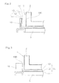
- the heat-resisting guide includes a mica plate and a carbon material. While the heat-resisting guide 20 is arranged only in a corner in Fig.
- the heat-resisting guide may be formed on an entire back surface of the lid 3.
- a fire-spread-prevention plate 21 covers the back surface of the lid 3 and is a laminate of a mica plate 22, a heat-insulating material 23, a fire-resisting material 24, and a mica plate 25.
- the mica plates 22, 25 are resistant to heat at about 1400°C.
- the high-temperature molten material that has spouted upward out of the cell 4 is blocked by the fire-spread-prevention plate 21, and flows downward along an inner surface of the heat-resisting guide 20 as indicated by arrows, to be introduced to the reservoir space 100 formed along the perimeter of the casing 1. Accordingly, an accident in which the high-temperature molten material penetrates the top lid 3 to spout together with a combustion flame can be prevented.
- the present invention even when an accident occurs to generate a high-temperature molten material inside the casing 1, the high-temperature molten material does not leak out of the casing 1, and therefore the safety is attained.
Landscapes
- Chemical & Material Sciences (AREA)
- Chemical Kinetics & Catalysis (AREA)
- Electrochemistry (AREA)
- General Chemical & Material Sciences (AREA)
- Engineering & Computer Science (AREA)
- Manufacturing & Machinery (AREA)
- Inorganic Chemistry (AREA)
- Composite Materials (AREA)
- Materials Engineering (AREA)
- Secondary Cells (AREA)
- Battery Mounting, Suspending (AREA)
Abstract
Description
- The present invention relates to a sodium-sulfur battery capable of preventing fire from spreading to an adjacent module, even when a high-temperature molten material is generated in a module at the time of an accident.
- A power storage system using a sodium-sulfur battery includes the required number of module batteries that are combined depending on the storage capacity. Each module has a large number such as hundreds of cells contained inside a heat-insulating container. The module batteries are housed in multiple vertical tiers within a rack, and are installed as a sodium-sulfur battery package.
- A sodium-sulfur battery module is a cell assembly contained inside a housing that is a heat-insulating module container. The cell has a structure in which molten metallic sodium serving as a negative-electrode active material is located in one part and molten sulfur serving as a positive-electrode active material is located in another part, and in which the both active materials are separated by a β-alumina solid electrolyte selectively permeable to sodium ions. The cell is heat controlled for each module at 300 to 350°C. Since the cell is a high-temperature cell which operates in such high temperature conditions, various safety measures have been taken.
- However, there remains a possibility that the cell be broken to cause a high-temperature molten material to flow into the inside of the heat-insulating container and cross an inter-block sand layer to reach an adjacent block of the cells which short-circuit, and a large number of the cells be broken by heat generated by short-circuit current to cause fire to spread to the entire module. Moreover, there remains a possibility that, once a fire occurs, the fire be not confined to the inside of the casing which is hermetically sealed, and fire spread to horizontally and vertically adjacent modules within the package to cause the extensive fire.
- Thus, as described in
Patent Literature 1, it has been proposed to place a heat-resisting plate such as carbon cloth in the upper inside of a casing which included in a module, in order to prevent a flame from going outside at the time of fire. However, since the heat-resisting plate has a low strength, the heat-resisting plate easily deforms by pressure of a high-temperature molten material generated at the time of fire. As a result, there has remained a possibility that a top lid be broken by such pressure to cause the high-temperature molten material to spout and fire spread to an upper module. Furthermore, there has remained a possibility that the high-temperature molten material melt and penetrate the top lid by heat thereof to spout together with a combustion flame. - Patent Literature 1:
JP 3253888 B1 - Therefore, it is an objective of the present invention to solve the above described problems and to provide a highly safe sodium-sulfur battery capable of preventing fire from spreading to an adjacent module owing to a high-temperature molten material even when an accident occurs due to some cause to generate the high-temperature molten material inside a casing which is a module container.
- To solve the above problems, a sodium-sulfur battery according to an aspect of the present invention is a sodium-sulfur battery having a plurality of cells contained in a casing provided with a top lid and including a heat-insulating layer, wherein a reservoir space is formed to retain and solidify a high-temperature molten material having flowed out of the cells.
- According to a second aspect of the invention, the reservoir space is formed by a reservoir container including a composite member of a rigid member, a heat-insulating material, and a heat-resisting material, the reservoir container is laid between the casing and a casing pallet which supports the casing, and the reservoir container has a side wall standing with a gap between the side wall and an outer wall surface of the casing.
- According to a third aspect of the invention, the reservoir space is formed by the composite member of the rigid member, the heat-insulating material, and the heat-resisting material that is laid between the casing and the casing pallet which supports the casing, and a steel member standing with a gap between the steel member and the outer wall surface of the casing.
- According to a fourth aspect of the invention, the reservoir space is formed by a reservoir container including a composite member of the heat-insulating material and the heat-resisting material, and the reservoir space is located in a space containing the cells within the casing.
- According to a fifth aspect of the invention, the reservoir space is formed by a reservoir container including the composite member of the heat-insulating material and the heat-resisting material, and the reservoir space is located within the heat-insulating layer included in the casing.
- Note that, according to a sixth aspect of the invention, the heat-insulating material preferably includes a ceramic fiber blanket or a mica material, and the heat-resisting material preferably includes a carbon material.
- According to a seventh aspect of the invention, a heat-resisting guide is disposed in a gap between a casing body and the top lid on an inner surface of the top lid of the casing.
- According to an eighth aspect of the invention, the heat-resisting guide can include a heat-insulating material and a fire-resisting material, and, according to a ninth aspect of the invention, the heat-resisting guide can include a mica plate and a carbon material.
- In the sodium-sulfur battery according to the present invention, the reservoir space is formed to retain and solidify the high-temperature molten material having flowed out of the cells. Therefore, even when the high-temperature molten material is generated at the time of fire, the high-temperature molten material is retained inside the reservoir space. Although the high-temperature molten material may reach a temperature of more than 2000°C, the material solidifies while retained within the reservoir space, without leaking out of the reservoir space. Accordingly, the spread of fire to an adjacent module can reliably be prevented. Note that a position and a form of the reservoir space can adopt various aspects as described in the second aspect to the fifth aspect.
- Furthermore, as described in the seventh aspect, when the heat-resisting guide is disposed in the gap between the casing body and the top lid on the inner surface of the top lid of the casing, the high-temperature molten material flows along the heat-resisting guide into the reservoir space via the side of the casing. Therefore, the high-temperature molten material does not penetrate the top lid to spout upward.
-
-
Fig. 1 is a cross-sectional view showing an entire configuration of a module battery. -
Fig. 2 is a cross-sectional view showing an embodiment according to the second aspect of the invention. -
Fig. 3 is a cross-sectional view showing an embodiment according to the third aspect of the invention. -
Fig. 4 is a cross-sectional view showing an embodiment according to the fourth aspect of the invention. -
Fig. 5 is a cross-sectional view showing an embodiment according to the fifth aspect of the invention. -
Fig. 6 is a cross-sectional view showing an embodiment according to the sixth aspect of the invention. - Preferred embodiments of the present invention are described below.
-
Fig. 1 shows a heat-insulating casing (a module container) 1 including acasing body 2 and atop lid 3. A plurality ofcells 4 is contained inside the casing. Thecasing body 2 and thetop lid 3 each have a heat-insulating structure in which a heat-insulating layer is formed inside a stainless-steel outer covering. Thecasing 1 is supported on acasing pallet 5. Thecasing pallet 5 is a steel structure also called a slide base. - As described above, each
cell 4 has a structure in which molten metallic sodium serving as a negative-electrode active material is located in one part, and molten sulfur serving as a positive-electrode active material is located in another part and in which the both active materials are separated by a beta-alumina solid electrolyte selectively permeable to sodium ions. Sodium ions pass through a wall surface of a beta-alumina tube serving as the solid electrolyte, whereby charging and discharging are performed. - When the beta-alumina tube in the
cell 4 is broken due to some cause, molten metallic sodium serving as the negative-electrode active material and molten sulfur serving as the positive-electrode active material may react to generate a high-temperature molten material having a temperature that exceeds 2000°C. When such a high-temperature molten material spreads inside thecasing 1, there is a possibility that theadjacent cell 4 be also affected and that, in the worst case, the high-temperature molten material flow out of thecasing 1 together with a combustion flame to cause fire to spread to the upper or laterallyadjacent casing 1. Thus, in the present invention, areservoir space 100 is formed to retain and solidify the high-temperature molten material having flowed out of thecells 4. Specific configurations of thereservoir space 100 will be described below. -
Fig. 2 is a cross-sectional view showing an embodiment according to the second aspect of the invention. Areservoir container 10 includes acomposite member 15 of arigid member 11, a heat-insulatingmaterial 12, and a heat-resistingmaterial 13. Therigid member 11 is preferably a steel plate, and is a member for giving mechanical strength to thereservoir container 10. The heat-insulatingmaterial 12 is a ceramic fiber blanket or a mica material. The heat-resistingmaterial 13 is a carbon material such as a carbon sheet which withstands contact with the high-temperature molten material. Thereservoir container 10 is laid between thecasing body 2 and thecasing pallet 5 which supports the casing body. Thereservoir container 10 has aside wall 14 standing with a gap between an outer wall surface of thecasing body 2 and an inner wall surface of thereservoir container 10, and thereservoir space 100 is formed outside thecasing body 2. - The
side wall 14 is set to have a height of approximately 5 to 10 cm, and the reservoir space is set to have a volume that can retain the high-temperature molten material having flowed out of a lower part of thecasing body 2. Since thereservoir space 100 is in constant contact with the ambient air, the high-temperature molten material retained therein rapidly solidifies without leaking out of thereservoir space 100. When thereservoir space 100 for the high-temperature molten material is formed along a perimeter of a bottom of thecasing 1 in this way, the high-temperature molten material that has flowed out of the lower part of thecasing body 2 does not reach theadjacent casing 1, and a fire can be confined within a single module battery. Therefore, the extent of accidental damage is limited. -
Fig. 3 is a cross-sectional view showing an embodiment according to the third aspect of the invention. In the embodiment shown inFig. 2 , thereservoir container 10 has theside wall 14 standing with the gap between theside wall 14 and the outer wall surface of thecasing body 2, and thereservoir space 100 is formed outside thecasing 1. On the other hand, in the embodiment shown inFig. 3 , thecomposite member 15 of therigid member 11, the heat-insulatingmaterial 12, and the heat-resistingmaterial 13 is laid between thecasing body 2 and thecasing pallet 5 which supports thecasing 1 while asteel member 16 stands with a gap between the steel member and the outer wall surface of thecasing body 2, and thereservoir space 100 is formed. Thisreservoir space 100 serves a similar function to that of thereservoir space 100 shown inFig. 2 . -
Fig. 4 is a cross-sectional view showing an embodiment according to the fourth aspect of the invention. According to this embodiment, areservoir container 18 including acomposite member 17 of the heat-insulatingmaterial 12 and the heat-resistingmaterial 13 is disposed in a space containing thecells 4 inside thecasing 1, and thereservoir space 100 is formed inside thecasing body 2. With such a structure, at the time of accident, the high-temperature molten material is retained within thereservoir space 100 inside thecasing body 2. Therefore, the high-temperature molten material does not melt a bottom of thecasing body 2 to flow downward out of thecasing body 2. In contrast to the above-described embodiments, thecomposite member 17 of the heat-insulatingmaterial 12 and the heat-resistingmaterial 13 is used because an inner wall of thecasing body 2 fulfils a function as therigid member 11. -
Fig. 5 is a cross-sectional view showing an embodiment according to the fifth aspect of the invention. According to the embodiment shown inFig. 4 , thereservoir space 100 is formed in the space containing thecells 4 inside thecasing 1. On the other hand, according to the embodiment shown inFig. 5 , thereservoir space 100 is formed within the heat-insulating layer included in thecasing body 2. That is, areservoir container 19 including thecomposite member 17 of the heat-insulatingmaterial 12 and the heat-resistingmaterial 13 is arranged on an inner surface of the outer covering of thecasing body 2, and thereservoir space 100 is formed within the heat-insulating layer. Again with the structure of this embodiment, the high-temperature molten material is retained within thereservoir space 100 inside thecasing 1. Therefore, the high-temperature molten material does not melt the bottom of thecasing body 2 to flow downward out of thecasing 1. -
Fig. 6 is a cross-sectional view showing an embodiment according to the seventh aspect of the invention. According to this embodiment, in order to prevent an accident in which the high-temperature molten material melts thetop lid 3 by heat thereof and penetrates thetop lid 3 of thecasing 1 to spout together with a combustion flame, a heat-resistingguide 20 is disposed in a gap between thecasing body 2 and thetop lid 3 on an inner surface of the top lid of thecasing 1. The heat-resistingguide 20 includes a heat-insulating material and a fire-resisting material. Specifically, the heat-resisting guide includes a mica plate and a carbon material. While the heat-resistingguide 20 is arranged only in a corner inFig. 6 , the heat-resisting guide may be formed on an entire back surface of thelid 3. Note that a fire-spread-prevention plate 21 covers the back surface of thelid 3 and is a laminate of amica plate 22, a heat-insulatingmaterial 23, a fire-resistingmaterial 24, and amica plate 25. Themica plates - With such a structure, the high-temperature molten material that has spouted upward out of the
cell 4 is blocked by the fire-spread-prevention plate 21, and flows downward along an inner surface of the heat-resistingguide 20 as indicated by arrows, to be introduced to thereservoir space 100 formed along the perimeter of thecasing 1. Accordingly, an accident in which the high-temperature molten material penetrates thetop lid 3 to spout together with a combustion flame can be prevented. - As heretofore described, according to the present invention, even when an accident occurs to generate a high-temperature molten material inside the
casing 1, the high-temperature molten material does not leak out of thecasing 1, and therefore the safety is attained. -
- 1 casing
- 2 casing body
- 3 top lid
- 4 cell
- 5 casing pallet
- 10 reservoir container
- 11 rigid member
- 12 heat-insulating material
- 13 heat-resisting material
- 14 side wall
- 15 composite member
- 16 steel member
- 17 composite member
- 18 reservoir container
- 19 reservoir container
- 20 heat-resisting guide
- 21 fire-spread-prevention plate
- 22 mica plate
- 23 heat-insulating material
- 24 fire-resisting material
- 25 mica plate
- 100 reservoir space
Claims (9)
- A sodium-sulfur battery having a plurality of cells contained in a casing provided with a top lid and including a heat-insulating layer,
wherein a reservoir space is formed to retain and solidify a high-temperature molten material having flowed out of the cells. - The sodium-sulfur battery according to claim 1,
wherein the reservoir space is formed by a reservoir container including a composite member of a rigid member, a heat-insulating material, and a heat-resisting material,
the reservoir container is laid between the casing and a casing pallet which supports the casing, and
the reservoir container has a side wall standing with a gap between the side wall and an outer wall surface of the casing. - The sodium-sulfur battery according to claim 1,
wherein the reservoir space is formed by the composite member of the rigid member, the heat-insulating material, and the heat-resisting material that is laid between the casing and the casing pallet which supports the casing, and a steel member standing with a gap between the steel member and the outer wall surface of the casing. - The sodium-sulfur battery according to claim 1,
wherein the reservoir space is formed by a reservoir container including a composite member of the heat-insulating material and the heat-resisting material, and
the reservoir space is located in a space containing the cells within the casing. - The sodium-sulfur battery according to claim 1,
wherein the reservoir space is formed by a reservoir container including the composite member of the heat-insulating material and the heat-resisting material, and
the reservoir space is located within the heat-insulating layer included in the casing. - The sodium-sulfur battery according to any one of claims 2 to 5,
wherein the heat-insulating material comprises a ceramic fiber blanket or a mica material, and
the heat-resisting material comprises a carbon material. - The sodium-sulfur battery according to any one of claims 1 to 6,
wherein a heat-resisting guide is disposed in a gap between a casing body and the top lid on an inner surface of the top lid of the casing. - The sodium-sulfur battery according to claim 7,
wherein the heat-resisting guide comprises a heat-insulating material and a fire-resisting material. - The sodium-sulfur battery according to claim 7,
wherein the heat-resisting guide comprises a mica plate and a carbon material.
Applications Claiming Priority (2)
| Application Number | Priority Date | Filing Date | Title |
|---|---|---|---|
| JP2012200335 | 2012-09-12 | ||
| PCT/JP2013/074384 WO2014042149A1 (en) | 2012-09-12 | 2013-09-10 | Sodium-sulfur battery |
Publications (3)
| Publication Number | Publication Date |
|---|---|
| EP2897211A1 true EP2897211A1 (en) | 2015-07-22 |
| EP2897211A4 EP2897211A4 (en) | 2016-04-06 |
| EP2897211B1 EP2897211B1 (en) | 2018-01-03 |
Family
ID=50278260
Family Applications (1)
| Application Number | Title | Priority Date | Filing Date |
|---|---|---|---|
| EP13836927.7A Active EP2897211B1 (en) | 2012-09-12 | 2013-09-10 | Sodium-sulfur battery |
Country Status (5)
| Country | Link |
|---|---|
| US (1) | US9742040B2 (en) |
| EP (1) | EP2897211B1 (en) |
| JP (1) | JP6021028B2 (en) |
| CN (1) | CN104508900B (en) |
| WO (1) | WO2014042149A1 (en) |
Families Citing this family (6)
| Publication number | Priority date | Publication date | Assignee | Title |
|---|---|---|---|---|
| JP6461674B2 (en) * | 2015-03-30 | 2019-01-30 | エスペック株式会社 | Containment |
| CN107394254B (en) * | 2016-05-16 | 2022-05-13 | 松下知识产权经营株式会社 | Battery with a battery cell |
| CN208690353U (en) * | 2018-09-20 | 2019-04-02 | 宁德时代新能源科技股份有限公司 | Battery case |
| DE102019211088A1 (en) * | 2019-07-25 | 2021-01-28 | Audi Ag | Battery case, battery and automobile |
| CN113386589A (en) * | 2020-03-11 | 2021-09-14 | 华晨宝马汽车有限公司 | Upper guard for electric vehicle battery |
| DE102021101234A1 (en) * | 2021-01-21 | 2022-07-21 | Bayerische Motoren Werke Aktiengesellschaft | Energy storage device and motor vehicle |
Family Cites Families (12)
| Publication number | Priority date | Publication date | Assignee | Title |
|---|---|---|---|---|
| GB1582845A (en) * | 1976-11-22 | 1981-01-14 | Chloride Silent Power Ltd | Electrochemical cells |
| US4110515A (en) * | 1977-02-28 | 1978-08-29 | Ford Motor Company | Method of preparing composite body and secondary battery or cell incorporating such composite body |
| JPS557428A (en) * | 1978-06-30 | 1980-01-19 | Yuasa Battery Co Ltd | Multilayer heat insulator |
| US4895776A (en) * | 1987-03-12 | 1990-01-23 | Ceramatec, Inc. | Electrochemical cell utilizing selenium as an electrode-reactant |
| JP2561764B2 (en) * | 1991-08-30 | 1996-12-11 | 日本碍子株式会社 | Sodium-sulfur battery |
| JP2667772B2 (en) * | 1993-01-21 | 1997-10-27 | 日本碍子株式会社 | Storage structure of sodium-sulfur cell |
| JP2937789B2 (en) * | 1995-02-24 | 1999-08-23 | 日本碍子株式会社 | Vacuum insulated container for sodium-sulfur battery and method of manufacturing the same |
| JPH10294128A (en) * | 1997-02-24 | 1998-11-04 | Hitachi Ltd | High temperature sodium secondary battery module and battery system |
| JP3253888B2 (en) * | 1997-04-09 | 2002-02-04 | 日本碍子株式会社 | Sodium-sulfur battery |
| CN202395065U (en) * | 2011-12-16 | 2012-08-22 | 日本碍子株式会社 | Module cell |
| JP3177969U (en) * | 2012-06-14 | 2012-08-23 | 日本碍子株式会社 | Sodium sulfur battery package |
| JP3177968U (en) * | 2012-06-14 | 2012-08-23 | 日本碍子株式会社 | Sodium sulfur battery module |
-
2013
- 2013-09-10 WO PCT/JP2013/074384 patent/WO2014042149A1/en not_active Ceased
- 2013-09-10 JP JP2014535549A patent/JP6021028B2/en active Active
- 2013-09-10 CN CN201380040404.7A patent/CN104508900B/en active Active
- 2013-09-10 EP EP13836927.7A patent/EP2897211B1/en active Active
-
2015
- 2015-02-25 US US14/630,861 patent/US9742040B2/en active Active
Also Published As
| Publication number | Publication date |
|---|---|
| CN104508900A (en) | 2015-04-08 |
| EP2897211A4 (en) | 2016-04-06 |
| JP6021028B2 (en) | 2016-11-02 |
| US20150194706A1 (en) | 2015-07-09 |
| CN104508900B (en) | 2017-02-22 |
| WO2014042149A1 (en) | 2014-03-20 |
| JPWO2014042149A1 (en) | 2016-08-18 |
| EP2897211B1 (en) | 2018-01-03 |
| US9742040B2 (en) | 2017-08-22 |
Similar Documents
| Publication | Publication Date | Title |
|---|---|---|
| US9742040B2 (en) | Sodium-sulfur battery | |
| JP3177969U (en) | Sodium sulfur battery package | |
| JP2022523777A (en) | Battery module and battery pack | |
| ES2772725T3 (en) | Device for storing electrical energy, as well as the procedure for its assembly and commissioning and for its operation | |
| JP5703504B2 (en) | Sodium sulfur battery package | |
| KR20220013575A (en) | Batteries and related devices, manufacturing methods and manufacturing facilities | |
| US12431557B2 (en) | Battery pack with cooling circuit | |
| EP2579380B9 (en) | Solid electrolyte secondary battery | |
| WO2019107560A1 (en) | Partition member and battery pack | |
| CN115149152A (en) | Battery with a battery cell | |
| CN106654114A (en) | Power battery structure and car | |
| JP2009070628A (en) | Lead storage battery | |
| EP3096373A1 (en) | Liquid electrolyte lithium accumulator and a method of making the same | |
| JP2024518275A (en) | Can-type battery module including liquid immersion cooling section | |
| JP7043813B2 (en) | Partition members and assembled batteries | |
| KR101585841B1 (en) | Core catcher having enhanced core cooling performance | |
| WO2021024664A1 (en) | Battery module | |
| CN118236653A (en) | Fireproof partition fire extinguishing device, fire extinguishing method and lithium battery energy storage system | |
| EP3297065B1 (en) | High capacity lithium accumulator with enhanced safety | |
| CN214957157U (en) | Fireproof battery pack and battery module | |
| RU2717076C1 (en) | Device for protection of lithium-ion battery from ignition | |
| JP6647803B2 (en) | Air battery system and parts for liquid injection | |
| CN224104776U (en) | Storage facilities and battery production systems | |
| CZ33343U1 (en) | Lithium battery safety system and a lithium battery with this system | |
| JP2014137953A (en) | Molten salt battery system, and operation method of molten salt battery system |
Legal Events
| Date | Code | Title | Description |
|---|---|---|---|
| PUAI | Public reference made under article 153(3) epc to a published international application that has entered the european phase |
Free format text: ORIGINAL CODE: 0009012 |
|
| 17P | Request for examination filed |
Effective date: 20150305 |
|
| AK | Designated contracting states |
Kind code of ref document: A1 Designated state(s): AL AT BE BG CH CY CZ DE DK EE ES FI FR GB GR HR HU IE IS IT LI LT LU LV MC MK MT NL NO PL PT RO RS SE SI SK SM TR |
|
| AX | Request for extension of the european patent |
Extension state: BA ME |
|
| DAX | Request for extension of the european patent (deleted) | ||
| RA4 | Supplementary search report drawn up and despatched (corrected) |
Effective date: 20160304 |
|
| RIC1 | Information provided on ipc code assigned before grant |
Ipc: H01M 2/10 20060101ALI20160229BHEP Ipc: H01M 10/39 20060101AFI20160229BHEP |
|
| REG | Reference to a national code |
Ref country code: DE Ref legal event code: R079 Ref document number: 602013031777 Country of ref document: DE Free format text: PREVIOUS MAIN CLASS: H01M0010390000 Ipc: H01M0010658000 |
|
| GRAP | Despatch of communication of intention to grant a patent |
Free format text: ORIGINAL CODE: EPIDOSNIGR1 |
|
| RIC1 | Information provided on ipc code assigned before grant |
Ipc: H01M 2/10 20060101ALI20170508BHEP Ipc: H01M 10/39 20060101ALI20170508BHEP Ipc: H01M 10/658 20140101AFI20170508BHEP |
|
| INTG | Intention to grant announced |
Effective date: 20170609 |
|
| GRAJ | Information related to disapproval of communication of intention to grant by the applicant or resumption of examination proceedings by the epo deleted |
Free format text: ORIGINAL CODE: EPIDOSDIGR1 |
|
| INTC | Intention to grant announced (deleted) | ||
| GRAR | Information related to intention to grant a patent recorded |
Free format text: ORIGINAL CODE: EPIDOSNIGR71 |
|
| GRAS | Grant fee paid |
Free format text: ORIGINAL CODE: EPIDOSNIGR3 |
|
| GRAA | (expected) grant |
Free format text: ORIGINAL CODE: 0009210 |
|
| INTG | Intention to grant announced |
Effective date: 20171122 |
|
| AK | Designated contracting states |
Kind code of ref document: B1 Designated state(s): AL AT BE BG CH CY CZ DE DK EE ES FI FR GB GR HR HU IE IS IT LI LT LU LV MC MK MT NL NO PL PT RO RS SE SI SK SM TR |
|
| REG | Reference to a national code |
Ref country code: GB Ref legal event code: FG4D |
|
| REG | Reference to a national code |
Ref country code: CH Ref legal event code: EP Ref country code: AT Ref legal event code: REF Ref document number: 961080 Country of ref document: AT Kind code of ref document: T Effective date: 20180115 |
|
| REG | Reference to a national code |
Ref country code: IE Ref legal event code: FG4D |
|
| REG | Reference to a national code |
Ref country code: DE Ref legal event code: R096 Ref document number: 602013031777 Country of ref document: DE |
|
| REG | Reference to a national code |
Ref country code: NL Ref legal event code: MP Effective date: 20180103 |
|
| REG | Reference to a national code |
Ref country code: LT Ref legal event code: MG4D |
|
| REG | Reference to a national code |
Ref country code: AT Ref legal event code: MK05 Ref document number: 961080 Country of ref document: AT Kind code of ref document: T Effective date: 20180103 |
|
| PG25 | Lapsed in a contracting state [announced via postgrant information from national office to epo] |
Ref country code: NL Free format text: LAPSE BECAUSE OF FAILURE TO SUBMIT A TRANSLATION OF THE DESCRIPTION OR TO PAY THE FEE WITHIN THE PRESCRIBED TIME-LIMIT Effective date: 20180103 |
|
| PG25 | Lapsed in a contracting state [announced via postgrant information from national office to epo] |
Ref country code: CY Free format text: LAPSE BECAUSE OF FAILURE TO SUBMIT A TRANSLATION OF THE DESCRIPTION OR TO PAY THE FEE WITHIN THE PRESCRIBED TIME-LIMIT Effective date: 20180103 Ref country code: HR Free format text: LAPSE BECAUSE OF FAILURE TO SUBMIT A TRANSLATION OF THE DESCRIPTION OR TO PAY THE FEE WITHIN THE PRESCRIBED TIME-LIMIT Effective date: 20180103 Ref country code: ES Free format text: LAPSE BECAUSE OF FAILURE TO SUBMIT A TRANSLATION OF THE DESCRIPTION OR TO PAY THE FEE WITHIN THE PRESCRIBED TIME-LIMIT Effective date: 20180103 Ref country code: LT Free format text: LAPSE BECAUSE OF FAILURE TO SUBMIT A TRANSLATION OF THE DESCRIPTION OR TO PAY THE FEE WITHIN THE PRESCRIBED TIME-LIMIT Effective date: 20180103 Ref country code: FI Free format text: LAPSE BECAUSE OF FAILURE TO SUBMIT A TRANSLATION OF THE DESCRIPTION OR TO PAY THE FEE WITHIN THE PRESCRIBED TIME-LIMIT Effective date: 20180103 Ref country code: NO Free format text: LAPSE BECAUSE OF FAILURE TO SUBMIT A TRANSLATION OF THE DESCRIPTION OR TO PAY THE FEE WITHIN THE PRESCRIBED TIME-LIMIT Effective date: 20180403 |
|
| PG25 | Lapsed in a contracting state [announced via postgrant information from national office to epo] |
Ref country code: SE Free format text: LAPSE BECAUSE OF FAILURE TO SUBMIT A TRANSLATION OF THE DESCRIPTION OR TO PAY THE FEE WITHIN THE PRESCRIBED TIME-LIMIT Effective date: 20180103 Ref country code: LV Free format text: LAPSE BECAUSE OF FAILURE TO SUBMIT A TRANSLATION OF THE DESCRIPTION OR TO PAY THE FEE WITHIN THE PRESCRIBED TIME-LIMIT Effective date: 20180103 Ref country code: PL Free format text: LAPSE BECAUSE OF FAILURE TO SUBMIT A TRANSLATION OF THE DESCRIPTION OR TO PAY THE FEE WITHIN THE PRESCRIBED TIME-LIMIT Effective date: 20180103 Ref country code: AT Free format text: LAPSE BECAUSE OF FAILURE TO SUBMIT A TRANSLATION OF THE DESCRIPTION OR TO PAY THE FEE WITHIN THE PRESCRIBED TIME-LIMIT Effective date: 20180103 Ref country code: IS Free format text: LAPSE BECAUSE OF FAILURE TO SUBMIT A TRANSLATION OF THE DESCRIPTION OR TO PAY THE FEE WITHIN THE PRESCRIBED TIME-LIMIT Effective date: 20180503 Ref country code: BG Free format text: LAPSE BECAUSE OF FAILURE TO SUBMIT A TRANSLATION OF THE DESCRIPTION OR TO PAY THE FEE WITHIN THE PRESCRIBED TIME-LIMIT Effective date: 20180403 Ref country code: GR Free format text: LAPSE BECAUSE OF FAILURE TO SUBMIT A TRANSLATION OF THE DESCRIPTION OR TO PAY THE FEE WITHIN THE PRESCRIBED TIME-LIMIT Effective date: 20180404 Ref country code: RS Free format text: LAPSE BECAUSE OF FAILURE TO SUBMIT A TRANSLATION OF THE DESCRIPTION OR TO PAY THE FEE WITHIN THE PRESCRIBED TIME-LIMIT Effective date: 20180103 |
|
| REG | Reference to a national code |
Ref country code: DE Ref legal event code: R097 Ref document number: 602013031777 Country of ref document: DE |
|
| PG25 | Lapsed in a contracting state [announced via postgrant information from national office to epo] |
Ref country code: AL Free format text: LAPSE BECAUSE OF FAILURE TO SUBMIT A TRANSLATION OF THE DESCRIPTION OR TO PAY THE FEE WITHIN THE PRESCRIBED TIME-LIMIT Effective date: 20180103 Ref country code: IT Free format text: LAPSE BECAUSE OF FAILURE TO SUBMIT A TRANSLATION OF THE DESCRIPTION OR TO PAY THE FEE WITHIN THE PRESCRIBED TIME-LIMIT Effective date: 20180103 Ref country code: RO Free format text: LAPSE BECAUSE OF FAILURE TO SUBMIT A TRANSLATION OF THE DESCRIPTION OR TO PAY THE FEE WITHIN THE PRESCRIBED TIME-LIMIT Effective date: 20180103 Ref country code: EE Free format text: LAPSE BECAUSE OF FAILURE TO SUBMIT A TRANSLATION OF THE DESCRIPTION OR TO PAY THE FEE WITHIN THE PRESCRIBED TIME-LIMIT Effective date: 20180103 |
|
| PLBE | No opposition filed within time limit |
Free format text: ORIGINAL CODE: 0009261 |
|
| STAA | Information on the status of an ep patent application or granted ep patent |
Free format text: STATUS: NO OPPOSITION FILED WITHIN TIME LIMIT |
|
| PG25 | Lapsed in a contracting state [announced via postgrant information from national office to epo] |
Ref country code: SK Free format text: LAPSE BECAUSE OF FAILURE TO SUBMIT A TRANSLATION OF THE DESCRIPTION OR TO PAY THE FEE WITHIN THE PRESCRIBED TIME-LIMIT Effective date: 20180103 Ref country code: CZ Free format text: LAPSE BECAUSE OF FAILURE TO SUBMIT A TRANSLATION OF THE DESCRIPTION OR TO PAY THE FEE WITHIN THE PRESCRIBED TIME-LIMIT Effective date: 20180103 Ref country code: DK Free format text: LAPSE BECAUSE OF FAILURE TO SUBMIT A TRANSLATION OF THE DESCRIPTION OR TO PAY THE FEE WITHIN THE PRESCRIBED TIME-LIMIT Effective date: 20180103 Ref country code: SM Free format text: LAPSE BECAUSE OF FAILURE TO SUBMIT A TRANSLATION OF THE DESCRIPTION OR TO PAY THE FEE WITHIN THE PRESCRIBED TIME-LIMIT Effective date: 20180103 |
|
| 26N | No opposition filed |
Effective date: 20181005 |
|
| PG25 | Lapsed in a contracting state [announced via postgrant information from national office to epo] |
Ref country code: SI Free format text: LAPSE BECAUSE OF FAILURE TO SUBMIT A TRANSLATION OF THE DESCRIPTION OR TO PAY THE FEE WITHIN THE PRESCRIBED TIME-LIMIT Effective date: 20180103 |
|
| PG25 | Lapsed in a contracting state [announced via postgrant information from national office to epo] |
Ref country code: MC Free format text: LAPSE BECAUSE OF FAILURE TO SUBMIT A TRANSLATION OF THE DESCRIPTION OR TO PAY THE FEE WITHIN THE PRESCRIBED TIME-LIMIT Effective date: 20180103 |
|
| REG | Reference to a national code |
Ref country code: CH Ref legal event code: PL |
|
| REG | Reference to a national code |
Ref country code: BE Ref legal event code: MM Effective date: 20180930 |
|
| REG | Reference to a national code |
Ref country code: IE Ref legal event code: MM4A |
|
| PG25 | Lapsed in a contracting state [announced via postgrant information from national office to epo] |
Ref country code: LU Free format text: LAPSE BECAUSE OF NON-PAYMENT OF DUE FEES Effective date: 20180910 |
|
| PG25 | Lapsed in a contracting state [announced via postgrant information from national office to epo] |
Ref country code: IE Free format text: LAPSE BECAUSE OF NON-PAYMENT OF DUE FEES Effective date: 20180910 |
|
| PG25 | Lapsed in a contracting state [announced via postgrant information from national office to epo] |
Ref country code: BE Free format text: LAPSE BECAUSE OF NON-PAYMENT OF DUE FEES Effective date: 20180930 Ref country code: LI Free format text: LAPSE BECAUSE OF NON-PAYMENT OF DUE FEES Effective date: 20180930 Ref country code: CH Free format text: LAPSE BECAUSE OF NON-PAYMENT OF DUE FEES Effective date: 20180930 Ref country code: FR Free format text: LAPSE BECAUSE OF NON-PAYMENT OF DUE FEES Effective date: 20180930 |
|
| PG25 | Lapsed in a contracting state [announced via postgrant information from national office to epo] |
Ref country code: MT Free format text: LAPSE BECAUSE OF NON-PAYMENT OF DUE FEES Effective date: 20180910 |
|
| PG25 | Lapsed in a contracting state [announced via postgrant information from national office to epo] |
Ref country code: TR Free format text: LAPSE BECAUSE OF FAILURE TO SUBMIT A TRANSLATION OF THE DESCRIPTION OR TO PAY THE FEE WITHIN THE PRESCRIBED TIME-LIMIT Effective date: 20180103 |
|
| PG25 | Lapsed in a contracting state [announced via postgrant information from national office to epo] |
Ref country code: PT Free format text: LAPSE BECAUSE OF FAILURE TO SUBMIT A TRANSLATION OF THE DESCRIPTION OR TO PAY THE FEE WITHIN THE PRESCRIBED TIME-LIMIT Effective date: 20180103 |
|
| PG25 | Lapsed in a contracting state [announced via postgrant information from national office to epo] |
Ref country code: HU Free format text: LAPSE BECAUSE OF FAILURE TO SUBMIT A TRANSLATION OF THE DESCRIPTION OR TO PAY THE FEE WITHIN THE PRESCRIBED TIME-LIMIT; INVALID AB INITIO Effective date: 20130910 Ref country code: MK Free format text: LAPSE BECAUSE OF NON-PAYMENT OF DUE FEES Effective date: 20180103 |
|
| PGFP | Annual fee paid to national office [announced via postgrant information from national office to epo] |
Ref country code: DE Payment date: 20250730 Year of fee payment: 13 |
|
| PGFP | Annual fee paid to national office [announced via postgrant information from national office to epo] |
Ref country code: GB Payment date: 20250731 Year of fee payment: 13 |