EP2897150A1 - Unit for controlling electromagnetic relay, and method for controlling electromagnetic relay - Google Patents
Unit for controlling electromagnetic relay, and method for controlling electromagnetic relay Download PDFInfo
- Publication number
- EP2897150A1 EP2897150A1 EP13837310.5A EP13837310A EP2897150A1 EP 2897150 A1 EP2897150 A1 EP 2897150A1 EP 13837310 A EP13837310 A EP 13837310A EP 2897150 A1 EP2897150 A1 EP 2897150A1
- Authority
- EP
- European Patent Office
- Prior art keywords
- electromagnetic relay
- relay
- accordance
- exciting coil
- electromagnetic
- Prior art date
- Legal status (The legal status is an assumption and is not a legal conclusion. Google has not performed a legal analysis and makes no representation as to the accuracy of the status listed.)
- Granted
Links
Images








Classifications
-
- H—ELECTRICITY
- H01—ELECTRIC ELEMENTS
- H01H—ELECTRIC SWITCHES; RELAYS; SELECTORS; EMERGENCY PROTECTIVE DEVICES
- H01H47/00—Circuit arrangements not adapted to a particular application of the relay and designed to obtain desired operating characteristics or to provide energising current
- H01H47/22—Circuit arrangements not adapted to a particular application of the relay and designed to obtain desired operating characteristics or to provide energising current for supplying energising current for relay coil
-
- H—ELECTRICITY
- H01—ELECTRIC ELEMENTS
- H01H—ELECTRIC SWITCHES; RELAYS; SELECTORS; EMERGENCY PROTECTIVE DEVICES
- H01H47/00—Circuit arrangements not adapted to a particular application of the relay and designed to obtain desired operating characteristics or to provide energising current
- H01H47/02—Circuit arrangements not adapted to a particular application of the relay and designed to obtain desired operating characteristics or to provide energising current for modifying the operation of the relay
- H01H2047/025—Circuit arrangements not adapted to a particular application of the relay and designed to obtain desired operating characteristics or to provide energising current for modifying the operation of the relay with taking into account of the thermal influences, e.g. change in resistivity of the coil or being adapted to high temperatures
-
- H—ELECTRICITY
- H01—ELECTRIC ELEMENTS
- H01H—ELECTRIC SWITCHES; RELAYS; SELECTORS; EMERGENCY PROTECTIVE DEVICES
- H01H47/00—Circuit arrangements not adapted to a particular application of the relay and designed to obtain desired operating characteristics or to provide energising current
- H01H47/02—Circuit arrangements not adapted to a particular application of the relay and designed to obtain desired operating characteristics or to provide energising current for modifying the operation of the relay
- H01H47/04—Circuit arrangements not adapted to a particular application of the relay and designed to obtain desired operating characteristics or to provide energising current for modifying the operation of the relay for holding armature in attracted position, e.g. when initial energising circuit is interrupted; for maintaining armature in attracted position, e.g. with reduced energising current
Definitions
- the present invention relates to a unit and a method each for controlling an electromagnetic relay which opens and closes a contact point by applying an electric current to an exciting coil.
- the unit is a relay drive circuit which turns on an electromagnetic relay by applying, to an exciting coil, a voltage equal to or higher than an operating voltage by use of a collector current with which a semiconductor switching element has been turned on.
- the unit is configured so as to, after turning on the electromagnetic relay, control the voltage, applied to the exciting coil, to be equal to or lower than the operating voltage and equal to or higher than a return voltage, in order to keep the electromagnetic relay turned on.
- the unit thus configured is capable of suppressing electric power consumption while keeping an electromagnetic relay turned on after turning the electromagnetic relay on.
- the unit having the aforementioned configuration, undesirably has difficulty in controlling the electromagnetic relay more suitably depending on the change in environment around the electromagnetic relay.
- the present invention has been made in view of the above problem, and an object of the present invention is to provide a unit and a method each for controlling an electromagnetic relay, each of which is capable of controlling an electromagnetic relay more suitably depending on a change in environment around the electromagnetic relay.
- a unit for controlling an electromagnetic relay in accordance with the present invention is a unit for controlling one or more electromagnetic relays each having a contact point and an exciting coil to which rated power is supplied so as to open and close the contact point, the unit including: a control circuit which carries out PWM control so as to keep an electromagnetic relay turned on, after turning on the electromagnetic relay by causing rated power to be supplied to an exciting coil of the electromagnetic relay, the control circuit changing, depending on external information, a controlling value in accordance with which the PWM control is carried out with respect to the electromagnetic relay.
- a method for controlling an electromagnetic relay in accordance with the present invention is a method for controlling one or more electromagnetic relays each having a contact point and an exciting coil to which rated power is supplied so as to open and close the contact point, the method including the step of: (a) carrying out PWM control so as to keep an electromagnetic relay turned on, after turning on the electromagnetic relay by causing rated power to be supplied to an exciting coil of the electromagnetic relay, in the step (a), a controlling value in accordance with which the PWM control is carried out with respect to the electromagnetic relay being changed depending on external information.
- a unit for controlling an electromagnetic relay in accordance with the present invention changes, depending on external information, a controlling value in accordance with which PWM control is carried out with respect to an electromagnetic relay.
- a control characteristic of an electromagnetic relay is affected by a temperature, vibration, an on- or off-state(s) of other electromagnetic relay(s) adjacent to the electromagnetic relay, a voltage applied to an exciting coil, and/or the like. Therefore, by changing, depending on such external information, the controlling value in accordance with which PWM control is carried out with respect to the electromagnetic relay, it is possible to control the electromagnetic relay more suitably depending on a change in environment around the electromagnetic relay.
- Fig. 1 is a block diagram illustrating a configuration of a relay control unit 1 (unit for controlling an electromagnetic relay) in accordance with Embodiment 1.
- the relay control unit 1 includes a communication section 12.
- the communication section 12 transmits/receives a command and data to/from a host controller 15.
- the relay control unit 1 further includes a control circuit 2.
- the control circuit 2 drives a plurality of relays 6 (electromagnetic relays), included in a relay unit 16, via respective drive circuits 10 in accordance with a command which the communication section 12 has received from the host controller 15.
- the control circuit 2 detects temperatures of the plurality of relays 6 via respective temperature detecting circuits 11.
- Each of the plurality of relays 6 has a movable contact point 8, a fixed contact point 9, and an exciting coil 7 to which rated power is supplied from a corresponding one of the drive circuits 10 so as to turn on/off the movable contact point 8.
- the relay control unit 1 includes a display section 13.
- the display section 13 displays how the control circuit 2 controls the plurality of relays 6.
- the relay control unit 1 further includes a memory 14.
- the memory 14 stores therein control data which the communication section 12 has received from the host controller 15 for control of each of the plurality of relays 6.
- Fig. 2 is a block diagram illustrating a configuration of a drive circuit 10 included in the relay control unit 1.
- the drive circuit 10 has a transistor TR1.
- the transistor TR1 supplies a drive current (rated power) to an exciting coil 7 of a corresponding relay 6 in response to a drive signal supplied from the control circuit 2.
- Fig. 3 is a block diagram illustrating a configuration of a temperature detecting circuit 11 included in the relay control unit 1.
- the temperature detecting circuit 11 has (i) a fixed resistor R1 connected to an exciting coil 7 of a corresponding relay 6 and (ii) a transistor TR2 connected to the fixed resistor R1.
- the control circuit 2 detects a temperature of the relay 6 in accordance with a change in resistance component of the exciting coil 7 which change is caused by a temperature of the exciting coil 7. While a corresponding drive circuit 10 is being turned off, the control circuit 2 turns on the transistor TR2, then measures a value of a voltage at an exciting coil 7 side of the fixed resistor R1, and converts the value into a temperature.
- the temperature detecting circuit 11 can be used to detect presence of a weld on a movable contact point 8 of the relay 6. That is, the control circuit 2 detects presence of a weld on the movable contact point 8 of the relay 6 in accordance with a change in inductance of the exciting coil 7 which change is caused by the presence of the weld on the movable contact point 8 the relay 6.
- the control circuit 2 detects the presence of the weld on the movable contact point 8 of the relay 6 in accordance with a transient response signal based on the exciting coil 7 and the fixed resistor R1.
- the transistor TR1 illustrated in Fig. 2 and the transistor TR2 illustrated in Fig. 3 are each not limited to a transistor.
- each of the transistors TR1 and TR2 can be replaced with a switching element which is turned on or off in response to an input signal supplied from outside.
- Examples of the switching element encompass an FET, a photo-coupler, and a relay.
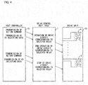
- Fig. 4 is a block diagram illustrating how the relay control unit 1 carries out PWM control.
- the host controller 15 transmits, to the relay control unit 1, (i) an action command which specifies each operation of the plurality of relays 6 and (ii) channel selecting data in accordance with which one of the plurality of relays 6, included in the relay unit 16, is selected.
- the relay control unit 1 selects the one of the plurality of relays 6 in accordance with the channel selecting data received from the host controller 15.
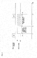
- Fig. 5 is a waveform chart illustrating how the PWM control is carried out.
- the relay control unit 1 operates a corresponding drive circuit 10, connected to an exciting coil 7 of a selected relay 6, so as to, during a time period T1 between a time t1 and a time t2, supply rated power to the exciting coil 7 of the relay 6 and accordingly turn on a movable contact point 8 of the relay 6. Then, during a time period T2 between the time t2 and a time t3, the relay control unit 1 carries out the PWM control, while supplying electric power approximately half of the rated power to the exciting coil 7, so as to keep the movable contact point 8 turned on.
- the host controller 15 transmits, to the relay control unit 1, (i) a return command (action command for turning off each relay) which instructs each return of the plurality of relays 6 and (ii) a channel selecting data.
- the relay control unit 1 stops operation of a corresponding drive circuit 10, connected to a relay 6 selected in accordance with the channel selecting data, by turning off a drive signal at the time t3.
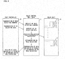
- Fig. 6 is a block diagram illustrating how the relay control unit 1 detects a weld.
- the host controller 15 transmits, to the relay control unit 1, (i) a weld detecting command which instructs detection of a weld on a movable contact point 8 of an exciting coil 7 and (ii) channel selecting data in accordance with which one of the plurality of relays 6 is selected.
- the relay control unit 1 receives the weld detecting command and the channel selecting data, and selects the one of the plurality of relays 6 in accordance with the channel selecting data thus received.
- the relay control unit 1 operates a corresponding temperature detecting circuit (weld detecting circuit) 11 so as to determine whether or not a weld is present on a movable contact point 8 of a selected relay 6. Thereafter, the relay control unit 1 transmits, to the host controller 15, a result of the determination made by the temperature detecting circuit (weld detecting circuit) 11 on whether or not a weld is present on the movable contact point 8. The host controller 15 receives, from the relay control unit 1, the result of the determination made on whether or not a weld is present on the movable contact point 8.
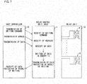
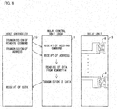
- Fig. 7 is a block diagram illustrating how the relay control unit 1 conducts memory writing operation.
- the relay control unit 1 writes, in the memory 14, each setting value of the plurality of relays 6.
- the host controller 15 transmits, to the relay control unit 1, (i) control data in accordance with which the plurality of relays 6 are controlled and which is to be written in the memory 14, (ii) a writing command which instructs writing of the control data in the memory 14, and (iii) an address of the memory 14 in which the control data is to be written.
- the relay control unit 1 receives the control data, the writing command, and the address each transmitted from the host controller 15.
- the relay control unit 1 then writes, in the memory 14, the control data received from the host controller 15, with reference to the address received from the host controller 15.
- the relay control unit 1 next transmits, to the host controller 15, data indicative of a result of the writing of the control data.
- the host controller 15 receives the data from the relay control unit 1.
- Fig, 8 is a block diagram illustrating how the relay control unit 1 conducts setting value reading operation.
- the relay control unit 1 reads out each setting value of the plurality of relays 6 which is stored in the memory 14.
- the host controller 15 transmits, to the relay control unit 1, (i) a reading command which instructs reading of control data, in accordance with which the plurality of relays 6 are controlled, from the memory 14, and (ii) an address of the memory 14 from which the control data is to be read out.
- the relay control unit 1 receives the reading command and the address transmitted from the host controller 15.
- the relay control unit 1 next reads out the control data from the memory 14 with reference to the address transmitted from the host controller 15. Thereafter, the relay control unit 1 transmits, to the host controller 15, the control data thus read out from the memory 14.
- the host controller 15 receives the control data transmitted from the relay control unit 1.
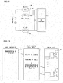
- Fig. 9 is a circuit diagram illustrating in what order the relay control unit 1 operates the relays.
- Fig. 10 is a view illustrating in what order the relays are operated.
- Fig. 11 illustrates a series of action commands in accordance with which the relay control unit operates the relays.
- one end of a relay 6b is connected to a positive electrode terminal of a power source, and the other end of the relay 6b is connected to the relay control unit 1.
- one end of the relay 6a is connected to the positive electrode terminal of the power source, and the other end of the relay 6a is connected to one end of a resistor. The other end of the resistor is connected to the relay control unit 1.
- One end of a relay 6c is connected to a negative electrode terminal of the power source, and the other end of the relay 6c is connected to the relay control unit 1.
- a capacitor is connected between the other end of the relay 6b and the other end of the relay 6c.
- the host controller 15 first transmits, to the relay control unit 1, a command which instructs the relay control unit 1 to operate the relays 6a, 6b, and 6b in a predetermined order.
- the relay control unit 1 receives the command transmitted from the host controller 15.
- the relay control unit 1 then read out, from the memory 14, a table stored in advance in the memory 14, and operates the relays 6a, 6b, and 6c in the following procedure.
- the relay control unit 1 operates the relay 6c, and then stands by for 1 (one) second.
- the relay control unit 1 operates the relay 6a, and then stands by for 5 seconds.
- the relay control unit 1 operates the relay 6b, and then stands by for 5 seconds.
- the relay control unit 1 returns the relay 6a, and then stands by for 1 (one) second.
- the relay control unit 1 carries out the PWM control with respect to the relays 6b and 6c. Thereafter, the relay control unit 1 ends the process.
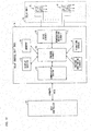
- Fig. 12 is a block diagram illustrating a configuration of a relay control unit 1a (electromagnetic relay) in accordance with Embodiment 2. Note that identical reference numerals are given to respective members identical to those in Embodiment 1, and the members will not be described below in detail.
- the relay control unit 1a includes a communication section 12.
- the communication section 12 transmits/receives a command and data to/from a host controller 15.
- the relay control unit 1a further includes a control circuit 2a.
- the control circuit 2a drives a plurality of relays 6 (electromagnetic relays), included in a relay unit 16, via respective drive circuits 10 in accordance with a command which the communication section 12 has received from the host controller 15.
- the control circuit 2 detects a weld on the plurality of relays 6 via respective temperature detecting circuits (weld detecting circuits) 11.
- Each of the plurality of relays 6 has a movable contact point 8, a fixed contact point 9, and an exciting coil 7 to which rated power is supplied from a corresponding one of the drive circuits 10 so as to turn on/off the movable contact point 8.
- the relay control unit 1a includes a display section 13.
- the display section 13 displays how the control circuit 2a controls the plurality of relays 6.
- the relay control unit 1a further includes a memory 14.
- the memory 14 stores therein control data which the communication section 12 has received from the host controller 15 for control of each of the plurality of relays 6.
- the relay control unit 1a further includes a vibration sensor 4 and voltage monitoring circuits 5, in addition to the temperature detecting circuits 11.
- Each of the temperature detecting circuits (weld detecting circuit) 11 converts, into a voltage, a resistance value which varies depending on a change in temperature of an exciting coil 7 of a corresponding one of the plurality of relays 6.
- the control circuit 2a converts the voltage into a temperature of the corresponding one of the plurality of relays 6.
- the control circuit 2a changes, depending on the temperature thus obtained, a controlling value in accordance with which the PWM control is carried out with respect to the corresponding one of the plurality of relays 6.
- the vibration sensor 4 detects vibration applied to each of the plurality of relays 6.
- the control circuit 2a changes, depending on a value of the vibration thus detected by the vibration sensor 4, a controlling value in accordance with which the PWM control is carried out with respect to the each of the plurality of relays 6.
- Each of the voltage monitoring circuits 5 monitors a coil voltage applied to an exciting coil 7 of a corresponding one of the plurality of relays 6.
- the control circuit 2a changes, depending on the coil voltage monitored by the each of the voltage monitoring circuit 5, a controlling value in accordance with which the PWM control is carried out with respect to the corresponding one of the plurality of relays 6.
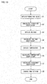
- Fig. 13 is a flowchart illustrating how the relay control unit 1a operates.
- the vibration sensor 4 detects vibration applied to a relay 6 (step S1).
- the control circuit 2a changes, depending on the vibration thus detected by the vibration sensor 4, a controlling value in accordance with which the PWM control is carried out with respect to the relay 6 (step S2).
- Fig. 14 is a graph illustrating how the relay control unit changes, depending on a value of vibration applied to a relay 6 (vibration value), a controlling value in accordance with which the PWM control is carried out (PWM controlling value).
- a region where a value of vibration, applied to the relay 6 and detected by the vibration sensor 4, is smaller than a vibration value ST1 is a stable region where the relay 6 stably operates.
- a region where a value of vibration applied to the relay 6 is not less than the vibration value ST1 and not more than a vibration value ST2, which is a rated vibration value, is an unstable region where the relay 6 does not stably operate.
- the control circuit 2a sets, to 1 (one), a vibration coefficient SK based on which the PWM controlling value is determined.
- the control circuit 2a linearly increases, depending on an increase in vibration value, the vibration coefficient SK, based on which the PWM controlling value is determined (see Fig. 14 ). For example, in a case where a vibration value increases to the vibration value ST2, the control circuit 2a increases the vibration coefficient SK to 1.5.
- the control circuit 2a thus changes the controlling value in accordance with which the PWM control is carried out with respect to the relay 6, depending on vibration which is applied to the relay 6 and which is detected by the vibration sensor 4.
- a corresponding voltage monitoring circuit 5 monitors a coil voltage applied to an exciting coil 7 of a relay 6.
- the control circuit 2a obtains data of the coil voltage monitored by the voltage monitoring circuit 5 (step S3).
- the control circuit 2a then calculates and changes, depending on the coil voltage, a voltage coefficient based on which the PWM controlling value, in accordance with which the PWM control is carried out with respect to the relay 6, is determined (step S4).
- Fig. 15 is a graph illustrating how the relay control unit 1a changes a PWM controlling value depending on a coil voltage.
- a horizontal axis indicates a voltage applied to an exciting coil 7 of a relay 6.
- a vertical axis indicates a voltage coefficient VK based on which the PWM controlling value, in accordance with which the PWM control is carried out with respect to the relay 6, is determined.
- the control circuit 2a sets the voltage coefficient VK, based on which the PWM controlling value is determined, to 1 (one). In a case where a voltage Vhigh of 14.4 V (standard upper limit voltage) is applied to the exciting coil 7, the control circuit 2a sets the voltage coefficient VK, based on which the PWM controlling value is determined, to 0.8. In a case where a voltage Vlow of 9.6V (standard lower limit voltage) is applied to the exciting coil 7, the control circuit 2a sets the voltage coefficient VK, based on which the PWM controlling value is determined, to 1.2.
- the control circuit 2a thus changes the controlling value in accordance with which the PWM control is carried out, depending on a voltage applied to the exciting coil 7. In a case where a voltage decreases, the control circuit 2a increases the voltage coefficient so that a time period during which PWM is turned on becomes longer.
- a corresponding temperature detecting circuit 11 detects a resistance value of an exciting coil 7 of a relay 6, and the control circuit 2a obtains data of a temperature of the relay 6 (step S5).
- the control circuit 2a then changes, depending on the temperature of the relay 6 thus obtained, a temperature coefficient TK based on which the PWM controlling value, in accordance with which the PWM control is carried out with respect to the relay 6, is determined (step S6).
- Fig. 16 is a circuit diagram illustrating configurations of a temperature detecting circuit (weld detecting circuit) 11 and a drive circuit 10 each of which is provided in the relay control unit 1a.
- the drive circuit 10 has a transistor TR1.
- the transistor TR1 supplies a drive current (rated power) to an exciting coil 7 of a corresponding relay 6 in response to a drive signal supplied from the control circuit 2a.
- the temperature detecting circuit (weld detecting circuit) 11 has (i) a fixed resistor R1 connected to the exciting coil 7 and (ii) a transistor TR2 connected to the fixed resistor R1.
- the control circuit 2a detects presence of a weld on a movable contact point 8 of the relay 6 in accordance with a change in inductance of the exciting coil 7 which change is caused by the presence of the weld on the movable contact point 8 of the relay 6.
- a step input signal is supplied to the transistor TR2 from the control circuit 2a while the drive circuit 10 is being turned off, the control circuit 2a detects the presence of the weld on the movable contact point 8 of the relay 6 in accordance with a transient response signal based on the exciting coil 7 and the fixed resistor R1.
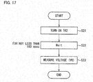
- Fig, 17 is a flowchart illustrating how the temperature detecting circuit (weld detecting circuit) 11 detects a resistance value of the exciting coil 7 and the control circuit 2a calculates a temperature of the exciting coil 7.
- Fig. 17 illustrates an example case where, before causing the drive circuit 10 to drive the relay 6, the control circuit 2a measures the temperature of the exciting coil 7.
- control circuit 2a turns on the transistor TR2 (step S21).
- the control circuit 2a then stands by for not less than 100 msec (step S22).
- the control circuit 2a measures a voltage VR at a point P positioned between the fixed resistor R1 and the exciting coil 7 (step S23).
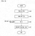
- Fig. 18 is a flowchart illustrating how, alternatively, the temperature detecting circuit (weld detecting circuit) 11 detects a resistance value of the exciting coil 7 and the control circuit 2a calculates a temperature of the exciting coil 7.
- Fig. 18 illustrates an example case where, while the relay 6 is in operation, the control circuit 2a measures the temperature of the exciting coil 7.
- control circuit 2a turns on the transistor TR2 (step S24).
- the control circuit 2a then turns off the transistor TR1 of the drive circuit 10 (step S25).
- the fixed resistor R1 is necessary to have a resistance value with which the relay 6 can be kept turned on.
- the control circuit 2a stands by for not less than 100 msec (step S26).
- the control circuit 2a measures a voltage VR at the point P positioned between the fixed resistor R1 and the exciting coil 7 (step S27).
- standby time of not less than 100 msec in each of the step S22 illustrated in Fig. 17 and the step S26 illustrated in Fig. 18 is a mere example.
- the standby time can be changed, provided that time can be secured which allows the voltage VR, at the point P positioned between the fixed resistor R1 and the exciting coil 7, to be in a steady state so that a resistance component of the exciting coil 7 is measured.
- the transistors TR1 and TR2 illustrated in Figs. 16 and 18 are each not limited to a transistor.
- each of the transistors TR1 and TR2 can be replaced with a switching element which is turned on or off in response to an input signal supplied from outside.
- the switching element encompass an FET, a photo-coupler, and a relay.
- Fig. 19 is a view illustrating a calculation expression by which a temperature of the exciting coil 7 is calculated.
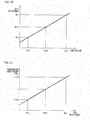
- Fig. 20 is a graph illustrating a relationship between a resistance value RL and a temperature of the exciting coil 7 of the relay 6, which resistance value RL and temperature are detected by the relay control unit 1a.
- a resistance value of the exciting coil 7, which is made up of a copper wire and which is provided to the relay 6, has a linear relationship with a temperature of the relay 6 (see Fig. 20 ).
- the relay 6 has a reference temperature Tref of 23°C.
- the relay 6 has a temperature TE1 of 85°C.
- the relay 6 has a temperature TE2 of -20°C.
- a temperature of the exciting coil 7 in accordance with a ratio between (i) the resistance value Rref of 25 ⁇ in a case where the relay 6 has the temperature Tref of 23°C and (ii) a resistance value of the exciting coil 7 which resistance value is detected by the temperature detecting circuit 11.
- Fig. 21 is a graph illustrating how the relay control unit 1a changes a PWM controlling value depending on a resistance value of the exciting coil 7.
- the control circuit 2a changes the temperature coefficient TK, based on which the PWM controlling value, in accordance with which the PWM control is carried out with respect to the relay 6, is determined, depending on a resistance value of the exciting coil 7 which resistance value is detected by the temperature detecting circuit 11 (see Fig. 21 ),
- the control circuit 2a sets the temperature coefficient TK, based on which the PWM controlling value is determined, to 1 (one).
- the control circuit 2a sets the temperature coefficient TK, based on which the PWM controlling value is determined, to 1.24.
- the control circuit 2a sets the temperature coefficient TK, based on which the PWM controlling value is determined, to 0.83.
- the control circuit 2a thus changes the controlling value in accordance with which the PWM control is carried out with respect to the relay 6, depending on a resistance value of the exciting coil 7 which resistance value is detected by the temperature detecting circuit 11.
- control circuit 2a changes a controlling value in accordance with which the PWM control is carried out with respect to one of the plurality of relays 6, depending on an on- or off-state(s) of other one(s) of the plurality of relays 6 which other one(s) is/are adjacent to the one of the plurality of relays 6.
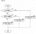
- Fig. 22 is a flowchart illustrating how the relay control unit 1a calculates an adjacency coefficient.
- (a) of Fig. 23 is a perspective view illustrating an external appearance of a relay 6 which the relay control unit 1a controls.
- (b) of Fig. 23 is a perspective view illustrating external appearances of relays 6 arranged so as to be adjacent to each other.
- the relays 6, included in the relay unit 16, are arranged so as to be adjacent to each other.
- a control characteristic of each of the relays 6 varies depending on an on- or off-state(s) of other one(s) of the relays 6 which other one(s) is/are adjacent to the each of the relays 6.
- the control circuit 2a first determines whether or not two of the plurality of relays 6, which two are adjacent to respective both sides of one of the plurality of relays 6, are tuned off (step S11). In a case where the control circuit 2a determines that the two of the plurality of relays 6 are turned off (Yes, in the step S11), the control circuit 2a sets, to 1 (one), an adjacency coefficient RK based on which the PWM controlling value is determined (step S13).
- control circuit 2a determines whether or not only one of the two of the plurality of relays 6 is turned on (step S12). In a case where the control circuit 2a determines that only one of the two of the plurality of relays 6 is turned on (Yes, in the step S12), the control circuit 2a sets the adjacency coefficient RK, based on which the PWM controlling value is determined, to 0.99 (step S14).
- control circuit 2a determines that only one of the two of the plurality of relays 6 is not turned on (No, in the step S12), the control circuit 2a determines that both of the two of the plurality of relays 6 are turned on, and sets the adjacency coefficient RK, based on which the PWM controlling value is determined, to 0.985 (step S15).
- control circuit 2a sets the adjacency coefficient RK, based on which the PWM controlling value is determined, to 1 (one) (in the step S13), to 0.99 (in the step S14), or to 0.985 (in the step S15), the control circuit 2a ends the process.
- the control circuit 2a sets the adjacency coefficient (in the step S7) and then changes the controlling value in accordance with which the PWM control is carried out with respect to one of the plurality of relays 6 (in the step S8), depending on an on- or off-state(s) of other one(s) of the plurality of relays 6 which other one(s) is/are adjacent to the one of the plurality of relays 6.
- Fig. 24 is view illustrating how the relay control unit 1a calculates a PWM value.
- the control circuit 2a controls the relay 6 in accordance with a PWM value obtained by multiplying a PWM reference value by a voltage coefficient VK, a vibration coefficient SK, a temperature coefficient TK, and an adjacency coefficient RK, which are changed by the above methods described with reference to Figs. 14 through 22 .
- Embodiment 2 has described an example case where the PWM reference value is multiplied by the voltage coefficient VK, the vibration coefficient SK, the temperature coefficient TK, and the adjacency coefficient RK.
- the PWM reference value can be alternatively multiplied by one of the voltage coefficient VK, the vibration coefficient SK, the temperature coefficient TK, and the adjacency coefficient RK.
- the PWM reference value can be multiplied by a combination of any of the voltage coefficient VK, the vibration coefficient SK, the temperature coefficient TK, and the adjacency coefficient RK.
- a unit for controlling an electromagnetic relay in accordance with the present invention is a unit for controlling one or more electromagnetic relays each having a contact point and an exciting coil to which rated power is supplied so as to open and close the contact point, the unit including: a control circuit which carries out PWM control so as to keep an electromagnetic relay turned on, after turning on the electromagnetic relay by causing rated power to be supplied to an exciting coil of the electromagnetic relay, the control circuit changing, depending on external information, a controlling value in accordance with which the PWM control is carried out with respect to the electromagnetic relay.
- the electromagnetic relay suitably depending on a change in environment around the electromagnetic relay, such as a temperature of the electromagnetic relay, vibration of the electromagnetic relay, operation of an electromagnetic relay(s) adjacent to the electromagnetic relay, and a voltage applied to the exciting coil of the electromagnetic relay.
- the unit for controlling an electromagnetic relay in accordance with the present invention is preferably arranged so as to further include: a temperature detecting circuit for detecting a resistance value of the exciting coil so as to allow the control circuit to calculate a temperature of the electromagnetic relay, the control circuit (i) detecting, from the temperature detecting circuit, a voltage corresponding to the resistance value of the exciting coil, (ii) calculating the temperature of the electromagnetic relay, and (iii) changing, depending on the temperature of the electromagnetic relay thus calculated, the controlling value in accordance with which the PWM control is carried out with respect to the electromagnetic relay.
- the temperature detecting circuit detects a resistance value of the exciting coil to which rated power is supplied so as to open and close a contact point of the electromagnetic relay, and the control circuit calculates a temperature of the electromagnetic relay. It is therefore possible to more suitably control, with a simple configuration, the electromagnetic relay depending on the temperature of the electromagnetic relay.
- the unit for controlling an electromagnetic relay in accordance with the present invention is preferably arranged such that the temperature detecting circuit includes: a switching element which is controlled by the control circuit; and a fixed resistor provided between the switching element and the exciting coil.
- the switching element means a switch which is turned on or off in response to an input signal supplied from outside.
- Examples of the switching element encompass a transistor, an FET, a photo-coupler, and a relay.
- the unit for controlling an electromagnetic relay in accordance with the present invention is preferably arranged such that, after turning on the switching element, the control circuit measures a voltage at an exciting coil side of the fixed resistor, and calculates the temperature of the electromagnetic relay in accordance with the voltage thus measured.
- the temperature of the electromagnetic relay be detected before the electromagnetic relay is operated.
- the unit for controlling an electromagnetic relay in accordance with the present invention is preferably arranged such that, after turning on the switching element, the control circuit (i) measures a voltage at an exciting coil side of the fixed resistor, (ii) determines, in accordance with the voltage in a transient response state, whether or not a weld is present on a contact point of the electromagnetic relay, and (iii) calculates the temperature of the electromagnetic relay in accordance with the voltage in a steady state.
- the unit for controlling an electromagnetic relay in accordance with the present invention is preferably arranged so as to further include: a drive circuit having a drive switching element for supplying the rated power to the exciting coil, after turning on the switching element, the control circuit turning off the drive switching element, and calculating the temperature of the electromagnetic relay in accordance with the voltage which has been measured.
- the unit for controlling an electromagnetic relay in accordance with the present invention is preferably arranged such that the electromagnetic relay includes a plurality of electromagnetic relays connected in parallel to each other so as to be adjacent to each other; and the control circuit changes a controlling value in accordance with which the PWM control is carried out with respect to one of the plurality of electromagnetic relays, depending on an on- or off-state(s) of other one(s) of the plurality of electromagnetic relays which other one(s) is/are adjacent to the one of the plurality of electromagnetic relays.
- a controlling value, in accordance with which PWM control is carried out with respect to one of the plurality of electromagnetic relays, is changed depending on an on- or off-state(s) of other one(s) of the plurality of electromagnetic relays which other one(s) is/are adjacent to the one of the plurality of electromagnetic relays.
- a control characteristic of the electromagnetic relay is affected by an on- or off-state(s) of other electromagnetic relay(s) adjacent to the electromagnetic relay. It is therefore possible to more suitably control the electromagnetic relay depending on a change in environment around the electromagnetic relay, by changing, depending on the on- or off-state(s) of the other electromagnetic relay(s) adjacent to the electromagnetic relay, the controlling value in accordance with which the PWM control is carried out with respect to the electromagnetic relay.
- the unit for controlling an electromagnetic relay in accordance with the present invention is preferably arranged so as to further include a vibration sensor for detecting vibration applied to the electromagnetic relay, the control circuit changing, depending on a value of the vibration detected by the vibration sensor, the controlling value in accordance with which the PWM control is carried out with respect to the electromagnetic relay.
- the unit for controlling an electromagnetic relay in accordance with the present invention is preferably arranged so as to further include a voltage monitoring circuit for monitoring a voltage applied to the exciting coil, the control circuit changing, depending on the voltage monitored by the voltage monitoring circuit, the controlling value in accordance with which the PWM control is carried out with respect to the electromagnetic relay.
- a method of controlling an electromagnetic relay in accordance with the present invention is a method for controlling one or more electromagnetic relays each having a contact point and an exciting coil to which rated power is supplied so as to open and close the contact point, the method including the step of: (a) carrying out PWM control so as to keep an electromagnetic relay turned on, after turning on the electromagnetic relay by causing rated power to be supplied to an exciting coil of the electromagnetic relay, in the step (a), a controlling value in accordance with which the PWM control is carried out with respect to the electromagnetic relay being changed depending on external information.
- the method of controlling an electromagnetic relay in accordance with the present invention is preferably arranged so as to further include the step of: (b) detecting a resistance value of the exciting coil so as that a temperature of the electromagnetic relay is calculated, in the step (a), the temperature of the electromagnetic relay being calculated in accordance with a voltage corresponding to the resistance value of the exciting coil detected in the step (b), and the controlling value in accordance with which the PWM control is carried out with respect to the electromagnetic relay being changed depending on the temperature of the electromagnetic relay thus calculated.
- the method of controlling an electromagnetic relay in accordance with the present invention is preferably arranged such that: the electromagnetic relay includes a plurality of electromagnetic relays connected in parallel to each other so as to be adjacent to each other; and in the step (a), a controlling value in accordance with which the PWM control is carried out with respect to one of the plurality of electromagnetic relays is changed depending on an on- or off-state(s) of other one(s) of the plurality of electromagnetic relays which other one(s) is/are adjacent to the one of the plurality of electromagnetic relays.
- the method of controlling an electromagnetic relay in accordance with the present invention is preferably arranged so as to further include the step of: (c) detecting vibration applied to the electromagnetic relay, in the step (a), the controlling value in accordance with which the PWM control is carried out with respect to the electromagnetic relay being changed depending on a value of the vibration detected in the step (c).
- the method of controlling an electromagnetic relay in accordance with the present invention is preferably arranged so as to further include the step of: (d) monitoring a voltage applied to the exciting coil, in the step (a), the controlling value in accordance with which the PWM control is carried out with respect to the electromagnetic relay being changed depending on the voltage monitored in the step (d).
- the present invention is applicable to a unit for controlling an electromagnetic relay which opens and closes a contact point by applying an electric current to an exciting coil.
Landscapes
- Engineering & Computer Science (AREA)
- Power Engineering (AREA)
- Relay Circuits (AREA)
Description
- The present invention relates to a unit and a method each for controlling an electromagnetic relay which opens and closes a contact point by applying an electric current to an exciting coil.
- Conventionally, there has been known a unit for controlling an electromagnetic relay which unit turns on an electromagnetic relay by supplying rated power to the electromagnetic relay and then, in order to maintain an on-state of the electromagnetic relay, controls a voltage, applied to an exciting coil, to be equal to or lower than an operating voltage and equal to or higher than a return voltage (Patent Literature 1).
- The unit is a relay drive circuit which turns on an electromagnetic relay by applying, to an exciting coil, a voltage equal to or higher than an operating voltage by use of a collector current with which a semiconductor switching element has been turned on. The unit is configured so as to, after turning on the electromagnetic relay, control the voltage, applied to the exciting coil, to be equal to or lower than the operating voltage and equal to or higher than a return voltage, in order to keep the electromagnetic relay turned on.
- The unit thus configured is capable of suppressing electric power consumption while keeping an electromagnetic relay turned on after turning the electromagnetic relay on.
- Japanese Patent Application Publication, Tokukaihei No.
11-306943 A (Publication Date: November 5, 1999 - However, a control characteristic of an electromagnetic relay varies depending on a change in environment around the electromagnetic relay, such as a temperature and vibration. Therefore, the unit, having the aforementioned configuration, undesirably has difficulty in controlling the electromagnetic relay more suitably depending on the change in environment around the electromagnetic relay.
- The present invention has been made in view of the above problem, and an object of the present invention is to provide a unit and a method each for controlling an electromagnetic relay, each of which is capable of controlling an electromagnetic relay more suitably depending on a change in environment around the electromagnetic relay.
- A unit for controlling an electromagnetic relay in accordance with the present invention is a unit for controlling one or more electromagnetic relays each having a contact point and an exciting coil to which rated power is supplied so as to open and close the contact point, the unit including: a control circuit which carries out PWM control so as to keep an electromagnetic relay turned on, after turning on the electromagnetic relay by causing rated power to be supplied to an exciting coil of the electromagnetic relay, the control circuit changing, depending on external information, a controlling value in accordance with which the PWM control is carried out with respect to the electromagnetic relay.
- A method for controlling an electromagnetic relay in accordance with the present invention is a method for controlling one or more electromagnetic relays each having a contact point and an exciting coil to which rated power is supplied so as to open and close the contact point, the method including the step of: (a) carrying out PWM control so as to keep an electromagnetic relay turned on, after turning on the electromagnetic relay by causing rated power to be supplied to an exciting coil of the electromagnetic relay, in the step (a), a controlling value in accordance with which the PWM control is carried out with respect to the electromagnetic relay being changed depending on external information.
- A unit for controlling an electromagnetic relay in accordance with the present invention changes, depending on external information, a controlling value in accordance with which PWM control is carried out with respect to an electromagnetic relay. A control characteristic of an electromagnetic relay is affected by a temperature, vibration, an on- or off-state(s) of other electromagnetic relay(s) adjacent to the electromagnetic relay, a voltage applied to an exciting coil, and/or the like. Therefore, by changing, depending on such external information, the controlling value in accordance with which PWM control is carried out with respect to the electromagnetic relay, it is possible to control the electromagnetic relay more suitably depending on a change in environment around the electromagnetic relay.
-
-
Fig. 1 is a block diagram illustrating a configuration of a relay control unit in accordance withEmbodiment 1. -
Fig. 2 is a block diagram illustrating a configuration of a drive circuit included in the relay control unit. -
Fig. 3 is a block diagram illustrating a configuration of a temperature detecting circuit (weld detecting circuit) included in the relay control unit. -
Fig. 4 is a block diagram illustrating how the relay control unit carries out PWM control. -
Fig. 5 is a waveform chart illustrating how the PWM control is carried out. -
Fig. 6 is a block diagram illustrating how the relay control unit detects a weld. -
Fig. 7 is a block diagram illustrating how the relay control unit conducts memory writing operation. -
Fig. 8 is a block diagram illustrating how the relay control unit conducts setting value reading operation. -
Fig. 9 is a circuit diagram illustrating in what order the relay control unit operates relays. -
Fig. 10 is a block diagram illustrating in what order the relays are operated. -
Fig. 11 is a view illustrating a series of action commands in accordance with which the relay control unit operates the relays. -
Fig. 12 is a block diagram illustrating a configuration of a relay control unit in accordance withEmbodiment 2. -
Fig. 13 is a flowchart illustrating how the relay control unit operates. -
Fig. 14 is a graph illustrating how the relay control unit changes a PWM controlling value depending on a vibration value. -
Fig. 15 is a graph illustrating how the relay control unit changes a PWM controlling value depending on a voltage. -
Fig. 16 is a circuit diagram illustrating configurations of a temperature detecting circuit (weld detecting circuit) and a drive circuit each of which is provided in the relay control unit. -
Fig. 17 is a flowchart illustrating how the temperature detecting circuit (weld detecting circuit) detects a resistance value of an exciting coil and calculates a temperature of the exciting coil. -
Fig. 18 is a flowchart illustrating how the temperature detecting circuit (weld detecting circuit) alternatively detects a resistance value of the exciting coil and calculates a temperature of the exciting coil. -
Fig. 19 is a view illustrating a calculation expression by which a temperature of theexciting coil 7 is calculated. -
Fig. 20 is a graph illustrating a relationship between a resistance value and a temperature of a coil of a relay, which resistance value and temperature are detected by the relay control unit. -
Fig. 21 is a graph illustrating how the relay control unit changes a PWM controlling value depending on a resistance value. -
Fig. 22 is a flowchart illustrating how the relay control unit calculates an adjacency coefficient.- (a) of
Fig. 23 is a perspective view illustrating an external appearance of a relay which the relay control unit controls. (b) ofFig. 23 is a perspective view illustrating external appearances of relays arranged so as to be adjacent to each other.
- (a) of
-
Fig. 24 is a view illustrating how the relay control unit calculates a PWM value. - The following description will discuss, in detail, embodiments of the present invention.
-
Fig. 1 is a block diagram illustrating a configuration of a relay control unit 1 (unit for controlling an electromagnetic relay) in accordance withEmbodiment 1. Therelay control unit 1 includes acommunication section 12. Thecommunication section 12 transmits/receives a command and data to/from ahost controller 15. Therelay control unit 1 further includes acontrol circuit 2. Thecontrol circuit 2 drives a plurality of relays 6 (electromagnetic relays), included in arelay unit 16, viarespective drive circuits 10 in accordance with a command which thecommunication section 12 has received from thehost controller 15. Thecontrol circuit 2 detects temperatures of the plurality ofrelays 6 via respectivetemperature detecting circuits 11. - Each of the plurality of
relays 6 has amovable contact point 8, afixed contact point 9, and anexciting coil 7 to which rated power is supplied from a corresponding one of thedrive circuits 10 so as to turn on/off themovable contact point 8. - The
relay control unit 1 includes adisplay section 13. Thedisplay section 13 displays how thecontrol circuit 2 controls the plurality ofrelays 6. Therelay control unit 1 further includes amemory 14. Thememory 14 stores therein control data which thecommunication section 12 has received from thehost controller 15 for control of each of the plurality ofrelays 6. -
Fig. 2 is a block diagram illustrating a configuration of adrive circuit 10 included in therelay control unit 1. Thedrive circuit 10 has a transistor TR1. The transistor TR1 supplies a drive current (rated power) to anexciting coil 7 of acorresponding relay 6 in response to a drive signal supplied from thecontrol circuit 2. -
Fig. 3 is a block diagram illustrating a configuration of atemperature detecting circuit 11 included in therelay control unit 1. Thetemperature detecting circuit 11 has (i) a fixed resistor R1 connected to anexciting coil 7 of acorresponding relay 6 and (ii) a transistor TR2 connected to the fixed resistor R1. Thecontrol circuit 2 detects a temperature of therelay 6 in accordance with a change in resistance component of theexciting coil 7 which change is caused by a temperature of theexciting coil 7. While acorresponding drive circuit 10 is being turned off, thecontrol circuit 2 turns on the transistor TR2, then measures a value of a voltage at anexciting coil 7 side of the fixed resistor R1, and converts the value into a temperature. - Note that the
temperature detecting circuit 11 can be used to detect presence of a weld on amovable contact point 8 of therelay 6. That is, thecontrol circuit 2 detects presence of a weld on themovable contact point 8 of therelay 6 in accordance with a change in inductance of theexciting coil 7 which change is caused by the presence of the weld on themovable contact point 8 therelay 6. When a step input signal is supplied to the transistor TR2 from thecontrol circuit 2, thecontrol circuit 2 detects the presence of the weld on themovable contact point 8 of therelay 6 in accordance with a transient response signal based on theexciting coil 7 and the fixed resistor R1. - The transistor TR1 illustrated in
Fig. 2 and the transistor TR2 illustrated inFig. 3 are each not limited to a transistor. Alternatively, each of the transistors TR1 and TR2 can be replaced with a switching element which is turned on or off in response to an input signal supplied from outside. Examples of the switching element encompass an FET, a photo-coupler, and a relay. -
Fig. 4 is a block diagram illustrating how therelay control unit 1 carries out PWM control. First, thehost controller 15 transmits, to therelay control unit 1, (i) an action command which specifies each operation of the plurality ofrelays 6 and (ii) channel selecting data in accordance with which one of the plurality ofrelays 6, included in therelay unit 16, is selected. Therelay control unit 1 then selects the one of the plurality ofrelays 6 in accordance with the channel selecting data received from thehost controller 15. -
Fig. 5 is a waveform chart illustrating how the PWM control is carried out. Therelay control unit 1 operates acorresponding drive circuit 10, connected to anexciting coil 7 of a selectedrelay 6, so as to, during a time period T1 between a time t1 and a time t2, supply rated power to theexciting coil 7 of therelay 6 and accordingly turn on amovable contact point 8 of therelay 6. Then, during a time period T2 between the time t2 and a time t3, therelay control unit 1 carries out the PWM control, while supplying electric power approximately half of the rated power to theexciting coil 7, so as to keep themovable contact point 8 turned on. - Next, the
host controller 15 transmits, to therelay control unit 1, (i) a return command (action command for turning off each relay) which instructs each return of the plurality ofrelays 6 and (ii) a channel selecting data. Therelay control unit 1 stops operation of acorresponding drive circuit 10, connected to arelay 6 selected in accordance with the channel selecting data, by turning off a drive signal at the time t3. -
Fig. 6 is a block diagram illustrating how therelay control unit 1 detects a weld. Thehost controller 15 transmits, to therelay control unit 1, (i) a weld detecting command which instructs detection of a weld on amovable contact point 8 of anexciting coil 7 and (ii) channel selecting data in accordance with which one of the plurality ofrelays 6 is selected. Therelay control unit 1 receives the weld detecting command and the channel selecting data, and selects the one of the plurality ofrelays 6 in accordance with the channel selecting data thus received. - Next, the
relay control unit 1 operates a corresponding temperature detecting circuit (weld detecting circuit) 11 so as to determine whether or not a weld is present on amovable contact point 8 of a selectedrelay 6. Thereafter, therelay control unit 1 transmits, to thehost controller 15, a result of the determination made by the temperature detecting circuit (weld detecting circuit) 11 on whether or not a weld is present on themovable contact point 8. Thehost controller 15 receives, from therelay control unit 1, the result of the determination made on whether or not a weld is present on themovable contact point 8. -
Fig. 7 is a block diagram illustrating how therelay control unit 1 conducts memory writing operation. Therelay control unit 1 writes, in thememory 14, each setting value of the plurality ofrelays 6. - The
host controller 15 transmits, to therelay control unit 1, (i) control data in accordance with which the plurality ofrelays 6 are controlled and which is to be written in thememory 14, (ii) a writing command which instructs writing of the control data in thememory 14, and (iii) an address of thememory 14 in which the control data is to be written. - The
relay control unit 1 receives the control data, the writing command, and the address each transmitted from thehost controller 15. Therelay control unit 1 then writes, in thememory 14, the control data received from thehost controller 15, with reference to the address received from thehost controller 15. Therelay control unit 1 next transmits, to thehost controller 15, data indicative of a result of the writing of the control data. Thehost controller 15 receives the data from therelay control unit 1. -
Fig, 8 is a block diagram illustrating how therelay control unit 1 conducts setting value reading operation. Therelay control unit 1 reads out each setting value of the plurality ofrelays 6 which is stored in thememory 14. - The
host controller 15 transmits, to therelay control unit 1, (i) a reading command which instructs reading of control data, in accordance with which the plurality ofrelays 6 are controlled, from thememory 14, and (ii) an address of thememory 14 from which the control data is to be read out. Therelay control unit 1 receives the reading command and the address transmitted from thehost controller 15. Therelay control unit 1 next reads out the control data from thememory 14 with reference to the address transmitted from thehost controller 15. Thereafter, therelay control unit 1 transmits, to thehost controller 15, the control data thus read out from thememory 14. Thehost controller 15 receives the control data transmitted from therelay control unit 1. -
Fig. 9 is a circuit diagram illustrating in what order therelay control unit 1 operates the relays.Fig. 10 is a view illustrating in what order the relays are operated.Fig. 11 illustrates a series of action commands in accordance with which the relay control unit operates the relays. - According to
Fig. 9 , one end of arelay 6b is connected to a positive electrode terminal of a power source, and the other end of therelay 6b is connected to therelay control unit 1. Meanwhile, one end of therelay 6a is connected to the positive electrode terminal of the power source, and the other end of therelay 6a is connected to one end of a resistor. The other end of the resistor is connected to therelay control unit 1. - One end of a
relay 6c is connected to a negative electrode terminal of the power source, and the other end of therelay 6c is connected to therelay control unit 1. A capacitor is connected between the other end of therelay 6b and the other end of therelay 6c. - With this arrangement, the
host controller 15 first transmits, to therelay control unit 1, a command which instructs therelay control unit 1 to operate therelays relay control unit 1 receives the command transmitted from thehost controller 15. Therelay control unit 1 then read out, from thememory 14, a table stored in advance in thememory 14, and operates therelays - First, the
relay control unit 1 operates therelay 6c, and then stands by for 1 (one) second. Next, therelay control unit 1 operates therelay 6a, and then stands by for 5 seconds. Thereafter, therelay control unit 1 operates therelay 6b, and then stands by for 5 seconds. - Next, the
relay control unit 1 returns therelay 6a, and then stands by for 1 (one) second. Therelay control unit 1 carries out the PWM control with respect to therelays relay control unit 1 ends the process. -
Fig. 12 is a block diagram illustrating a configuration of arelay control unit 1a (electromagnetic relay) in accordance withEmbodiment 2. Note that identical reference numerals are given to respective members identical to those inEmbodiment 1, and the members will not be described below in detail. - The
relay control unit 1a includes acommunication section 12. Thecommunication section 12 transmits/receives a command and data to/from ahost controller 15. Therelay control unit 1a further includes acontrol circuit 2a. Thecontrol circuit 2a drives a plurality of relays 6 (electromagnetic relays), included in arelay unit 16, viarespective drive circuits 10 in accordance with a command which thecommunication section 12 has received from thehost controller 15. Thecontrol circuit 2 detects a weld on the plurality ofrelays 6 via respective temperature detecting circuits (weld detecting circuits) 11. - Each of the plurality of
relays 6 has amovable contact point 8, a fixedcontact point 9, and anexciting coil 7 to which rated power is supplied from a corresponding one of thedrive circuits 10 so as to turn on/off themovable contact point 8. - The
relay control unit 1a includes adisplay section 13. Thedisplay section 13 displays how thecontrol circuit 2a controls the plurality ofrelays 6. Therelay control unit 1a further includes amemory 14. Thememory 14 stores therein control data which thecommunication section 12 has received from thehost controller 15 for control of each of the plurality ofrelays 6. - The
relay control unit 1a further includes avibration sensor 4 andvoltage monitoring circuits 5, in addition to thetemperature detecting circuits 11. Each of the temperature detecting circuits (weld detecting circuit) 11 converts, into a voltage, a resistance value which varies depending on a change in temperature of anexciting coil 7 of a corresponding one of the plurality ofrelays 6. Thecontrol circuit 2a converts the voltage into a temperature of the corresponding one of the plurality ofrelays 6. Thecontrol circuit 2a changes, depending on the temperature thus obtained, a controlling value in accordance with which the PWM control is carried out with respect to the corresponding one of the plurality ofrelays 6. - The
vibration sensor 4 detects vibration applied to each of the plurality ofrelays 6. Thecontrol circuit 2a changes, depending on a value of the vibration thus detected by thevibration sensor 4, a controlling value in accordance with which the PWM control is carried out with respect to the each of the plurality ofrelays 6. - Each of the
voltage monitoring circuits 5 monitors a coil voltage applied to anexciting coil 7 of a corresponding one of the plurality ofrelays 6. Thecontrol circuit 2a changes, depending on the coil voltage monitored by the each of thevoltage monitoring circuit 5, a controlling value in accordance with which the PWM control is carried out with respect to the corresponding one of the plurality ofrelays 6. -
Fig. 13 is a flowchart illustrating how therelay control unit 1a operates. First, thevibration sensor 4 detects vibration applied to a relay 6 (step S1). Thecontrol circuit 2a changes, depending on the vibration thus detected by thevibration sensor 4, a controlling value in accordance with which the PWM control is carried out with respect to the relay 6 (step S2). -
Fig. 14 is a graph illustrating how the relay control unit changes, depending on a value of vibration applied to a relay 6 (vibration value), a controlling value in accordance with which the PWM control is carried out (PWM controlling value). A region where a value of vibration, applied to therelay 6 and detected by thevibration sensor 4, is smaller than a vibration value ST1 is a stable region where therelay 6 stably operates. Meanwhile, a region where a value of vibration applied to therelay 6 is not less than the vibration value ST1 and not more than a vibration value ST2, which is a rated vibration value, is an unstable region where therelay 6 does not stably operate. - In a case where a vibration value falls within the stable region, the
control circuit 2a sets, to 1 (one), a vibration coefficient SK based on which the PWM controlling value is determined. In a case where a vibration value falls within the unstable region, thecontrol circuit 2a linearly increases, depending on an increase in vibration value, the vibration coefficient SK, based on which the PWM controlling value is determined (seeFig. 14 ). For example, in a case where a vibration value increases to the vibration value ST2, thecontrol circuit 2a increases the vibration coefficient SK to 1.5. Thecontrol circuit 2a thus changes the controlling value in accordance with which the PWM control is carried out with respect to therelay 6, depending on vibration which is applied to therelay 6 and which is detected by thevibration sensor 4. - Again with reference to
Fig. 13 , a correspondingvoltage monitoring circuit 5 monitors a coil voltage applied to anexciting coil 7 of arelay 6. Thecontrol circuit 2a obtains data of the coil voltage monitored by the voltage monitoring circuit 5 (step S3). Thecontrol circuit 2a then calculates and changes, depending on the coil voltage, a voltage coefficient based on which the PWM controlling value, in accordance with which the PWM control is carried out with respect to therelay 6, is determined (step S4). -
Fig. 15 is a graph illustrating how therelay control unit 1a changes a PWM controlling value depending on a coil voltage. A horizontal axis indicates a voltage applied to anexciting coil 7 of arelay 6. A vertical axis indicates a voltage coefficient VK based on which the PWM controlling value, in accordance with which the PWM control is carried out with respect to therelay 6, is determined. - In a case where a voltage V of 12 V (rated voltage) is applied to the
exciting coil 7, thecontrol circuit 2a sets the voltage coefficient VK, based on which the PWM controlling value is determined, to 1 (one). In a case where a voltage Vhigh of 14.4 V (standard upper limit voltage) is applied to theexciting coil 7, thecontrol circuit 2a sets the voltage coefficient VK, based on which the PWM controlling value is determined, to 0.8. In a case where a voltage Vlow of 9.6V (standard lower limit voltage) is applied to theexciting coil 7, thecontrol circuit 2a sets the voltage coefficient VK, based on which the PWM controlling value is determined, to 1.2. Thecontrol circuit 2a thus changes the controlling value in accordance with which the PWM control is carried out, depending on a voltage applied to theexciting coil 7. In a case where a voltage decreases, thecontrol circuit 2a increases the voltage coefficient so that a time period during which PWM is turned on becomes longer. - Again with reference to
Fig. 13 , a correspondingtemperature detecting circuit 11 detects a resistance value of anexciting coil 7 of arelay 6, and thecontrol circuit 2a obtains data of a temperature of the relay 6 (step S5). Thecontrol circuit 2a then changes, depending on the temperature of therelay 6 thus obtained, a temperature coefficient TK based on which the PWM controlling value, in accordance with which the PWM control is carried out with respect to therelay 6, is determined (step S6). -
Fig. 16 is a circuit diagram illustrating configurations of a temperature detecting circuit (weld detecting circuit) 11 and adrive circuit 10 each of which is provided in therelay control unit 1a. Thedrive circuit 10 has a transistor TR1. The transistor TR1 supplies a drive current (rated power) to anexciting coil 7 of acorresponding relay 6 in response to a drive signal supplied from thecontrol circuit 2a. The temperature detecting circuit (weld detecting circuit) 11 has (i) a fixed resistor R1 connected to theexciting coil 7 and (ii) a transistor TR2 connected to the fixed resistor R1. Thecontrol circuit 2a detects presence of a weld on amovable contact point 8 of therelay 6 in accordance with a change in inductance of theexciting coil 7 which change is caused by the presence of the weld on themovable contact point 8 of therelay 6. When a step input signal is supplied to the transistor TR2 from thecontrol circuit 2a while thedrive circuit 10 is being turned off, thecontrol circuit 2a detects the presence of the weld on themovable contact point 8 of therelay 6 in accordance with a transient response signal based on theexciting coil 7 and the fixed resistor R1. -
Fig, 17 is a flowchart illustrating how the temperature detecting circuit (weld detecting circuit) 11 detects a resistance value of theexciting coil 7 and thecontrol circuit 2a calculates a temperature of theexciting coil 7.Fig. 17 illustrates an example case where, before causing thedrive circuit 10 to drive therelay 6, thecontrol circuit 2a measures the temperature of theexciting coil 7. - First, the
control circuit 2a turns on the transistor TR2 (step S21). Thecontrol circuit 2a then stands by for not less than 100 msec (step S22). Next, thecontrol circuit 2a measures a voltage VR at a point P positioned between the fixed resistor R1 and the exciting coil 7 (step S23). -
Fig. 18 is a flowchart illustrating how, alternatively, the temperature detecting circuit (weld detecting circuit) 11 detects a resistance value of theexciting coil 7 and thecontrol circuit 2a calculates a temperature of theexciting coil 7.Fig. 18 illustrates an example case where, while therelay 6 is in operation, thecontrol circuit 2a measures the temperature of theexciting coil 7. - First, the
control circuit 2a turns on the transistor TR2 (step S24). Thecontrol circuit 2a then turns off the transistor TR1 of the drive circuit 10 (step S25). Here, the fixed resistor R1 is necessary to have a resistance value with which therelay 6 can be kept turned on. Next, thecontrol circuit 2a stands by for not less than 100 msec (step S26). Thereafter, thecontrol circuit 2a measures a voltage VR at the point P positioned between the fixed resistor R1 and the exciting coil 7 (step S27). - Note that standby time of not less than 100 msec in each of the step S22 illustrated in
Fig. 17 and the step S26 illustrated inFig. 18 is a mere example. The standby time can be changed, provided that time can be secured which allows the voltage VR, at the point P positioned between the fixed resistor R1 and theexciting coil 7, to be in a steady state so that a resistance component of theexciting coil 7 is measured. - The transistors TR1 and TR2 illustrated in
Figs. 16 and18 are each not limited to a transistor. Alternatively, each of the transistors TR1 and TR2 can be replaced with a switching element which is turned on or off in response to an input signal supplied from outside. Examples of the switching element encompass an FET, a photo-coupler, and a relay. -
Fig. 19 is a view illustrating a calculation expression by which a temperature of theexciting coil 7 is calculated. A resistance value RL of theexciting coil 7 of therelay 6 is calculated from the followingExpression 1.
- R1 denotes a fixed resistance value of the temperature detecting circuit (weld detecting circuit) 11;
- VCC denotes a power source voltage;
- VL denotes a voltage corresponding to a resistance value RL (VL = VCC-VR); and
- VR denotes a voltage at the point P between the resistance value RL and the fixed resistor R1.
-
Fig. 20 is a graph illustrating a relationship between a resistance value RL and a temperature of theexciting coil 7 of therelay 6, which resistance value RL and temperature are detected by therelay control unit 1a. A resistance value of theexciting coil 7, which is made up of a copper wire and which is provided to therelay 6, has a linear relationship with a temperature of the relay 6 (seeFig. 20 ). For example, in a case where theexciting coil 7 has a resistance value Rref of 25 Ω (reference value), therelay 6 has a reference temperature Tref of 23°C. In a case where theexciting coil 7 has a resistance value RL1 of 31 Ω (reference value × 1.24), therelay 6 has a temperature TE1 of 85°C. In a case where theexciting coil 7 has a resistance value RL2 of 20.8 Ω (reference value × 0.83), therelay 6 has a temperature TE2 of -20°C. Thus, it is possible to calculate a temperature of theexciting coil 7 in accordance with a ratio between (i) the resistance value Rref of 25 Ω in a case where therelay 6 has the temperature Tref of 23°C and (ii) a resistance value of theexciting coil 7 which resistance value is detected by thetemperature detecting circuit 11. -
Fig. 21 is a graph illustrating how therelay control unit 1a changes a PWM controlling value depending on a resistance value of theexciting coil 7. Thecontrol circuit 2a changes the temperature coefficient TK, based on which the PWM controlling value, in accordance with which the PWM control is carried out with respect to therelay 6, is determined, depending on a resistance value of theexciting coil 7 which resistance value is detected by the temperature detecting circuit 11 (seeFig. 21 ), - For example, in a case where the
exciting coil 7 has the resistance value Rref of 25 Ω (reference value) which resistance value Rref is detected by thetemperature detecting circuit 11, thecontrol circuit 2a sets the temperature coefficient TK, based on which the PWM controlling value is determined, to 1 (one). In a case where theexciting coil 7 has the resistance RL1 of 31 Ω (reference value × 1.24), thecontrol circuit 2a sets the temperature coefficient TK, based on which the PWM controlling value is determined, to 1.24. In a case where theexciting coil 7 has the resistance value RL2 of 20.8 Ω (reference value × 0.83), thecontrol circuit 2a sets the temperature coefficient TK, based on which the PWM controlling value is determined, to 0.83. Thecontrol circuit 2a thus changes the controlling value in accordance with which the PWM control is carried out with respect to therelay 6, depending on a resistance value of theexciting coil 7 which resistance value is detected by thetemperature detecting circuit 11. - Again with reference to
Fig. 13 , thecontrol circuit 2a changes a controlling value in accordance with which the PWM control is carried out with respect to one of the plurality ofrelays 6, depending on an on- or off-state(s) of other one(s) of the plurality ofrelays 6 which other one(s) is/are adjacent to the one of the plurality ofrelays 6. -
Fig. 22 is a flowchart illustrating how therelay control unit 1a calculates an adjacency coefficient. (a) ofFig. 23 is a perspective view illustrating an external appearance of arelay 6 which therelay control unit 1a controls. (b) ofFig. 23 is a perspective view illustrating external appearances ofrelays 6 arranged so as to be adjacent to each other. - With reference to
Fig. 23 , therelays 6, included in therelay unit 16, are arranged so as to be adjacent to each other. A control characteristic of each of therelays 6 varies depending on an on- or off-state(s) of other one(s) of therelays 6 which other one(s) is/are adjacent to the each of therelays 6. - With reference to
Fig. 22 , thecontrol circuit 2a first determines whether or not two of the plurality ofrelays 6, which two are adjacent to respective both sides of one of the plurality ofrelays 6, are tuned off (step S11). In a case where thecontrol circuit 2a determines that the two of the plurality ofrelays 6 are turned off (Yes, in the step S11), thecontrol circuit 2a sets, to 1 (one), an adjacency coefficient RK based on which the PWM controlling value is determined (step S13). - In a case where the
control circuit 2a determines that at least one of the two of the plurality ofrelays 6 is turned on (No, in the step S11), thecontrol circuit 2a determines whether or not only one of the two of the plurality ofrelays 6 is turned on (step S12). In a case where thecontrol circuit 2a determines that only one of the two of the plurality ofrelays 6 is turned on (Yes, in the step S12), thecontrol circuit 2a sets the adjacency coefficient RK, based on which the PWM controlling value is determined, to 0.99 (step S14). - In a case where
control circuit 2a determines that only one of the two of the plurality ofrelays 6 is not turned on (No, in the step S12), thecontrol circuit 2a determines that both of the two of the plurality ofrelays 6 are turned on, and sets the adjacency coefficient RK, based on which the PWM controlling value is determined, to 0.985 (step S15). - In a case where the
control circuit 2a sets the adjacency coefficient RK, based on which the PWM controlling value is determined, to 1 (one) (in the step S13), to 0.99 (in the step S14), or to 0.985 (in the step S15), thecontrol circuit 2a ends the process. - In this manner, in a case where a plurality of
relays 6 are used, thecontrol circuit 2a sets the adjacency coefficient (in the step S7) and then changes the controlling value in accordance with which the PWM control is carried out with respect to one of the plurality of relays 6 (in the step S8), depending on an on- or off-state(s) of other one(s) of the plurality ofrelays 6 which other one(s) is/are adjacent to the one of the plurality ofrelays 6. -
Fig. 24 is view illustrating how therelay control unit 1a calculates a PWM value. Thecontrol circuit 2a controls therelay 6 in accordance with a PWM value obtained by multiplying a PWM reference value by a voltage coefficient VK, a vibration coefficient SK, a temperature coefficient TK, and an adjacency coefficient RK, which are changed by the above methods described with reference toFigs. 14 through 22 . - Note that
Embodiment 2 has described an example case where the PWM reference value is multiplied by the voltage coefficient VK, the vibration coefficient SK, the temperature coefficient TK, and the adjacency coefficient RK. However, the present invention is not limited to such an arrangement. The PWM reference value can be alternatively multiplied by one of the voltage coefficient VK, the vibration coefficient SK, the temperature coefficient TK, and the adjacency coefficient RK. Alternatively, the PWM reference value can be multiplied by a combination of any of the voltage coefficient VK, the vibration coefficient SK, the temperature coefficient TK, and the adjacency coefficient RK. - The present invention is not limited to the description of the embodiments, but may be altered by a skilled person in the art within the scope of the claims. An embodiment derived from a proper combination of technical means disclosed in different embodiments is also encompassed in the technical scope of the present invention.
- A unit for controlling an electromagnetic relay in accordance with the present invention is a unit for controlling one or more electromagnetic relays each having a contact point and an exciting coil to which rated power is supplied so as to open and close the contact point, the unit including: a control circuit which carries out PWM control so as to keep an electromagnetic relay turned on, after turning on the electromagnetic relay by causing rated power to be supplied to an exciting coil of the electromagnetic relay, the control circuit changing, depending on external information, a controlling value in accordance with which the PWM control is carried out with respect to the electromagnetic relay.
- With this feature, it is possible to control the electromagnetic relay suitably depending on a change in environment around the electromagnetic relay, such as a temperature of the electromagnetic relay, vibration of the electromagnetic relay, operation of an electromagnetic relay(s) adjacent to the electromagnetic relay, and a voltage applied to the exciting coil of the electromagnetic relay.
- The unit for controlling an electromagnetic relay in accordance with the present invention is preferably arranged so as to further include: a temperature detecting circuit for detecting a resistance value of the exciting coil so as to allow the control circuit to calculate a temperature of the electromagnetic relay, the control circuit (i) detecting, from the temperature detecting circuit, a voltage corresponding to the resistance value of the exciting coil, (ii) calculating the temperature of the electromagnetic relay, and (iii) changing, depending on the temperature of the electromagnetic relay thus calculated, the controlling value in accordance with which the PWM control is carried out with respect to the electromagnetic relay.
- With this feature, the temperature detecting circuit detects a resistance value of the exciting coil to which rated power is supplied so as to open and close a contact point of the electromagnetic relay, and the control circuit calculates a temperature of the electromagnetic relay. It is therefore possible to more suitably control, with a simple configuration, the electromagnetic relay depending on the temperature of the electromagnetic relay.
- The unit for controlling an electromagnetic relay in accordance with the present invention is preferably arranged such that the temperature detecting circuit includes: a switching element which is controlled by the control circuit; and a fixed resistor provided between the switching element and the exciting coil.
- Note that the switching element means a switch which is turned on or off in response to an input signal supplied from outside. Examples of the switching element encompass a transistor, an FET, a photo-coupler, and a relay.
- According to the above configuration, it is possible to detect, with a simple configuration, a voltage corresponding to the exciting coil.
- The unit for controlling an electromagnetic relay in accordance with the present invention is preferably arranged such that, after turning on the switching element, the control circuit measures a voltage at an exciting coil side of the fixed resistor, and calculates the temperature of the electromagnetic relay in accordance with the voltage thus measured.
- It is preferable that, with the above configuration, the temperature of the electromagnetic relay be detected before the electromagnetic relay is operated.
- The unit for controlling an electromagnetic relay in accordance with the present invention is preferably arranged such that, after turning on the switching element, the control circuit (i) measures a voltage at an exciting coil side of the fixed resistor, (ii) determines, in accordance with the voltage in a transient response state, whether or not a weld is present on a contact point of the electromagnetic relay, and (iii) calculates the temperature of the electromagnetic relay in accordance with the voltage in a steady state.
- According to the above configuration, it is possible to detect the temperature of the electromagnetic relay in accordance with a resistance component of the exciting coil, and possible to detect presence of a weld on the contact point in accordance with an inductive component of the exciting coil.
- The unit for controlling an electromagnetic relay in accordance with the present invention is preferably arranged so as to further include: a drive circuit having a drive switching element for supplying the rated power to the exciting coil, after turning on the switching element, the control circuit turning off the drive switching element, and calculating the temperature of the electromagnetic relay in accordance with the voltage which has been measured.
- According to the above configuration, it is possible to detect the temperature of the electromagnetic relay while the electromagnetic relay is in operation.
- The unit for controlling an electromagnetic relay in accordance with the present invention is preferably arranged such that the electromagnetic relay includes a plurality of electromagnetic relays connected in parallel to each other so as to be adjacent to each other; and the control circuit changes a controlling value in accordance with which the PWM control is carried out with respect to one of the plurality of electromagnetic relays, depending on an on- or off-state(s) of other one(s) of the plurality of electromagnetic relays which other one(s) is/are adjacent to the one of the plurality of electromagnetic relays.
- According the above configuration, a controlling value, in accordance with which PWM control is carried out with respect to one of the plurality of electromagnetic relays, is changed depending on an on- or off-state(s) of other one(s) of the plurality of electromagnetic relays which other one(s) is/are adjacent to the one of the plurality of electromagnetic relays. A control characteristic of the electromagnetic relay is affected by an on- or off-state(s) of other electromagnetic relay(s) adjacent to the electromagnetic relay. It is therefore possible to more suitably control the electromagnetic relay depending on a change in environment around the electromagnetic relay, by changing, depending on the on- or off-state(s) of the other electromagnetic relay(s) adjacent to the electromagnetic relay, the controlling value in accordance with which the PWM control is carried out with respect to the electromagnetic relay.
- The unit for controlling an electromagnetic relay in accordance with the present invention is preferably arranged so as to further include a vibration sensor for detecting vibration applied to the electromagnetic relay, the control circuit changing, depending on a value of the vibration detected by the vibration sensor, the controlling value in accordance with which the PWM control is carried out with respect to the electromagnetic relay.
- According to the above configuration, it is possible to more suitably control the electromagnetic relay depending on vibration applied to the electromagnetic relay.
- The unit for controlling an electromagnetic relay in accordance with the present invention is preferably arranged so as to further include a voltage monitoring circuit for monitoring a voltage applied to the exciting coil, the control circuit changing, depending on the voltage monitored by the voltage monitoring circuit, the controlling value in accordance with which the PWM control is carried out with respect to the electromagnetic relay.
- According to the above configuration, it is possible to more suitably control the electromagnetic relay depending on a voltage applied to the exciting coil to which rated power is supplied so as to open and close the contact point.
- A method of controlling an electromagnetic relay in accordance with the present invention is a method for controlling one or more electromagnetic relays each having a contact point and an exciting coil to which rated power is supplied so as to open and close the contact point, the method including the step of: (a) carrying out PWM control so as to keep an electromagnetic relay turned on, after turning on the electromagnetic relay by causing rated power to be supplied to an exciting coil of the electromagnetic relay, in the step (a), a controlling value in accordance with which the PWM control is carried out with respect to the electromagnetic relay being changed depending on external information.
- The method of controlling an electromagnetic relay in accordance with the present invention is preferably arranged so as to further include the step of: (b) detecting a resistance value of the exciting coil so as that a temperature of the electromagnetic relay is calculated, in the step (a), the temperature of the electromagnetic relay being calculated in accordance with a voltage corresponding to the resistance value of the exciting coil detected in the step (b), and the controlling value in accordance with which the PWM control is carried out with respect to the electromagnetic relay being changed depending on the temperature of the electromagnetic relay thus calculated.
- The method of controlling an electromagnetic relay in accordance with the present invention is preferably arranged such that: the electromagnetic relay includes a plurality of electromagnetic relays connected in parallel to each other so as to be adjacent to each other; and in the step (a), a controlling value in accordance with which the PWM control is carried out with respect to one of the plurality of electromagnetic relays is changed depending on an on- or off-state(s) of other one(s) of the plurality of electromagnetic relays which other one(s) is/are adjacent to the one of the plurality of electromagnetic relays.
- The method of controlling an electromagnetic relay in accordance with the present invention is preferably arranged so as to further include the step of: (c) detecting vibration applied to the electromagnetic relay, in the step (a), the controlling value in accordance with which the PWM control is carried out with respect to the electromagnetic relay being changed depending on a value of the vibration detected in the step (c).
- The method of controlling an electromagnetic relay in accordance with the present invention is preferably arranged so as to further include the step of: (d) monitoring a voltage applied to the exciting coil, in the step (a), the controlling value in accordance with which the PWM control is carried out with respect to the electromagnetic relay being changed depending on the voltage monitored in the step (d).
- The present invention is applicable to a unit for controlling an electromagnetic relay which opens and closes a contact point by applying an electric current to an exciting coil.
-
- 1
- Relay control unit (unit for controlling electromagnetic relay)
- 2
- Control circuit
- 4
- Vibration sensor
- 5
- Voltage monitoring circuit
- 6
- Relay (electromagnetic relay)
- 7
- Exciting coil
- 8
- Movable contact point
- 9
- Fixed contact point
- 10
- Drive circuit
- 11
- Temperature detecting circuit (weld detecting circuit)
- 12
- Communication section
- 13
- Display section
- 14
- Memory
- 15
- Host controller
- 16
- Relay unit
- TR1
- Transistor (drive switching element)
- TR2
- Transistor (switching element)
Claims (14)
- A unit for controlling one or more electromagnetic relays each having a contact point and an exciting coil to which rated power is supplied so as to open and close the contact point, the unit comprising:a control circuit which carries out PWM control so as to keep an electromagnetic relay turned on, after turning on the electromagnetic relay by causing rated power to be supplied to an exciting coil of the electromagnetic relay,the control circuit changing, depending on external information, a controlling value in accordance with which the PWM control is carried out with respect to the electromagnetic relay.
- A unit as set forth in claim 1, further comprising:a temperature detecting circuit for detecting a resistance value of the exciting coil so as to allow the control circuit to calculate a temperature of the electromagnetic relay,the control circuit (i) detecting, from the temperature detecting circuit, a voltage corresponding to the resistance value of the exciting coil, (ii) calculating the temperature of the electromagnetic relay, and (iii) changing, depending on the temperature of the electromagnetic relay thus calculated, the controlling value in accordance with which the PWM control is carried out with respect to the electromagnetic relay.
- The unit as set forth in claim 2, wherein the temperature detecting circuit includes:a switching element which is controlled by the control circuit; anda fixed resistor provided between the switching element and the exciting coil.
- The unit as set forth in claim 3, wherein, after turning on the switching element, the control circuit measures a voltage at an exciting coil side of the fixed resistor, and calculates the temperature of the electromagnetic relay in accordance with the voltage thus measured.
- The unit as set forth in claim 3, wherein, after turning on the switching element, the control circuit (i) measures a voltage at an exciting coil side of the fixed resistor, (ii) determines, in accordance with the voltage in a transient response state, whether or not a weld is present on a contact point of the electromagnetic relay, and (iii) calculates the temperature of the electromagnetic relay in accordance with the voltage in a steady state.
- A unit as set forth in claim 4, further comprising:a drive circuit having a drive switching element for supplying the rated power to the exciting coil,after turning on the switching element, the control circuit turning off the drive switching element, and calculating the temperature of the electromagnetic relay in accordance with the voltage which has been measured.
- The unit as set forth in claim 1 wherein:the electromagnetic relay includes a plurality of electromagnetic relays connected in parallel to each other so as to be adjacent to each other; andthe control circuit changes a controlling value in accordance with which the PWM control is carried out with respect to one of the plurality of electromagnetic relays, depending on an on- or off-state(s) of other one(s) of the plurality of electromagnetic relays which other one(s) is/are adjacent to the one of the plurality of electromagnetic relays.
- A unit as set forth in claim 1, further comprising
a vibration sensor for detecting vibration applied to the electromagnetic relay,
the control circuit changing, depending on a value of the vibration detected by the vibration sensor, the controlling value in accordance with which the PWM control is carried out with respect to the electromagnetic relay. - A unit as set forth in claim 1, further comprising:a voltage monitoring circuit for monitoring a voltage applied to the exciting coil,the control circuit changing, depending on the voltage monitored by the voltage monitoring circuit, the controlling value in accordance with which the PWM control is carried out with respect to the electromagnetic relay.
- A method for controlling one or more electromagnetic relays each having a contact point and an exciting coil to which rated power is supplied so as to open and close the contact point, the method comprising the step of:(a) carrying out PWM control so as to keep an electromagnetic relay turned on, after turning on the electromagnetic relay by causing rated power to be supplied to an exciting coil of the electromagnetic relay, in the step (a), a controlling value in accordance with which the PWM control is carried out with respect to the electromagnetic relay being changed depending on external information.
- A method as set forth in claim 10, further comprising the step of:(b) detecting a resistance value of the exciting coil so as that a temperature of the electromagnetic relay is calculated,
in the step (a), the temperature of the electromagnetic relay being calculated in accordance with a voltage corresponding to the resistance value of the exciting coil detected in the step (b), and the controlling value in accordance with which the PWM control is carried out with respect to the electromagnetic relay being changed depending on the temperature of the electromagnetic relay thus calculated. - The method as set forth in claim 10, wherein:the electromagnetic relay includes a plurality of electromagnetic relays connected in parallel to each other so as to be adjacent to each other; andin the step (a), a controlling value in accordance with which the PWM control is carried out with respect to one of the plurality of electromagnetic relays is changed depending on an on- or off-state(s) of other one(s) of the plurality of electromagnetic relays which other one(s) is/are adjacent to the one of the plurality of electromagnetic relays.
- A method as set forth in claim 10, further comprising the step of:(c) detecting vibration applied to the electromagnetic relay,
in the step (a), the controlling value in accordance with which the PWM control is carried out with respect to the electromagnetic relay being changed depending on a value of the vibration detected in the step (c). - A method as set forth in claim 10, further comprising the step of:(d) monitoring a voltage applied to the exciting coil,
in the step (a), the controlling value in accordance with which the PWM control is carried out with respect to the electromagnetic relay being changed depending on the voltage monitored in the step (d).
Applications Claiming Priority (2)
| Application Number | Priority Date | Filing Date | Title |
|---|---|---|---|
| JP2012199933A JP5408316B1 (en) | 2012-09-11 | 2012-09-11 | Electromagnetic relay control unit and electromagnetic relay control method |
| PCT/JP2013/068612 WO2014041883A1 (en) | 2012-09-11 | 2013-07-08 | Unit for controlling electromagnetic relay, and method for controlling electromagnetic relay |
Publications (3)
| Publication Number | Publication Date |
|---|---|
| EP2897150A1 true EP2897150A1 (en) | 2015-07-22 |
| EP2897150A4 EP2897150A4 (en) | 2016-04-27 |
| EP2897150B1 EP2897150B1 (en) | 2017-10-11 |
Family
ID=50202629
Family Applications (1)
| Application Number | Title | Priority Date | Filing Date |
|---|---|---|---|
| EP13837310.5A Active EP2897150B1 (en) | 2012-09-11 | 2013-07-08 | Unit for controlling electromagnetic relay, and method for controlling electromagnetic relay |
Country Status (6)
| Country | Link |
|---|---|
| US (1) | US9202651B2 (en) |
| EP (1) | EP2897150B1 (en) |
| JP (1) | JP5408316B1 (en) |
| KR (1) | KR101548906B1 (en) |
| CN (1) | CN104508786B (en) |
| WO (1) | WO2014041883A1 (en) |
Cited By (1)
| Publication number | Priority date | Publication date | Assignee | Title |
|---|---|---|---|---|
| EP3361491A1 (en) * | 2017-02-10 | 2018-08-15 | Pilz GmbH & Co. KG | Switching assembly for operating at least one relay |
Families Citing this family (16)
| Publication number | Priority date | Publication date | Assignee | Title |
|---|---|---|---|---|
| CN104253605A (en) * | 2013-06-27 | 2014-12-31 | 鸿富锦精密工业(深圳)有限公司 | Adjustment circuit and electronic device with same |
| CN103943410B (en) * | 2014-04-22 | 2016-01-20 | 宁波燎原电器集团股份有限公司 | Based on the auto-switch circuit of magnetic latching relay |
| US9807528B1 (en) * | 2015-09-21 | 2017-10-31 | Apple Inc. | Electronic devices and method for thermal monitoring of an electro-mechanical actuator |
| FR3054369B1 (en) * | 2016-07-20 | 2022-05-27 | Zodiac Aero Electric | ELECTROMAGNETIC CONTACTOR PROVIDED WITH MEANS FOR DETECTING THE OPEN OR CLOSED POSITION OF COMMAND SWITCHES |
| CN108933062B (en) * | 2017-05-24 | 2021-09-28 | 浙江正泰电器股份有限公司 | Relay setting system and intelligent relay |
| CN107170644B (en) * | 2017-06-16 | 2019-07-12 | 东南大学 | A kind of D.C. contactor energy-saving control device and control method |
| US10734177B2 (en) * | 2017-09-21 | 2020-08-04 | Moxa Inc. | Electromagnetic relay device and control method thereof |
| JP7096778B2 (en) * | 2019-02-08 | 2022-07-06 | 株式会社Subaru | Switch system |
| KR102154635B1 (en) | 2019-08-26 | 2020-09-10 | 엘에스일렉트릭(주) | Coil drive appatatus |
| US11004638B2 (en) * | 2019-09-26 | 2021-05-11 | Alstom Transport Technologies | System for monitoring an electromechanical relay, assembly and method for monitoring relay operation conditions |
| CN110571099B (en) * | 2019-10-11 | 2021-11-23 | 广东美的制冷设备有限公司 | Multi-relay control method, control circuit and air conditioner |
| JP7632322B2 (en) * | 2022-01-18 | 2025-02-19 | 株式会社デンソーエレクトロニクス | Relay control device, electronic control device, and relay temperature detection method |
| KR20230140894A (en) | 2022-03-30 | 2023-10-10 | 한국철도공사 | Vibratory relay contact test control system and method |
| JP2024077733A (en) * | 2022-11-29 | 2024-06-10 | オムロン株式会社 | Power circuit breaker, power circuit breaker system including the same, power circuit breaker protection method, and protection program |
| US20250023344A1 (en) * | 2023-07-10 | 2025-01-16 | Hamilton Sundstrand Corporation | ELECTRICAL LOAD CONTROL MONITORING UNITS (LCMUs) |
| US20260155325A1 (en) * | 2024-12-03 | 2026-06-04 | Allegro Microsystems, Llc | Contactor bounce reduction |
Family Cites Families (14)
| Publication number | Priority date | Publication date | Assignee | Title |
|---|---|---|---|---|
| JP3162827B2 (en) | 1992-09-18 | 2001-05-08 | 三洋電機株式会社 | Temperature control device |
| JPH11306943A (en) * | 1998-04-20 | 1999-11-05 | Hanshin Electric Co Ltd | Relay drive circuit |
| DE19935043B4 (en) | 1999-07-26 | 2005-12-01 | Moeller Gmbh | Circuit arrangement for the electronic control of a drive coil |
| JP2004178967A (en) * | 2002-11-27 | 2004-06-24 | Kayaba Ind Co Ltd | Relay control device |
| DE10341924A1 (en) * | 2003-09-11 | 2005-04-07 | Conti Temic Microelectronic Gmbh | Relay for car use has coil voltage and current sensor with microcontroller evaluation of temperature dependent impedance threshold |
| JP2005261039A (en) * | 2004-03-10 | 2005-09-22 | Fujitsu Ten Ltd | Switching power circuit |
| JP4525498B2 (en) * | 2005-07-08 | 2010-08-18 | オムロン株式会社 | Relay control device |
| JP2008192481A (en) * | 2007-02-06 | 2008-08-21 | Yazaki Corp | Relay control device |
| KR100802910B1 (en) | 2007-03-05 | 2008-02-13 | 엘에스산전 주식회사 | Coil Drive of Magnetic Contactor |
| JP5002332B2 (en) * | 2007-05-25 | 2012-08-15 | パナソニック株式会社 | Contact input terminal |
| JP2009289671A (en) * | 2008-05-30 | 2009-12-10 | Yazaki Corp | Relay control device |
| JP5225198B2 (en) * | 2009-05-20 | 2013-07-03 | 三菱電機株式会社 | Status monitoring device for switchgear or electromagnetic operating device |
| JP2011210385A (en) | 2010-03-29 | 2011-10-20 | Omron Automotive Electronics Co Ltd | Relay control device |
| WO2012069869A1 (en) * | 2010-11-26 | 2012-05-31 | Renault Trucks | Method for piloting a relay on-board an automotive vehicle |
-
2012
- 2012-09-11 JP JP2012199933A patent/JP5408316B1/en active Active
-
2013
- 2013-07-08 KR KR1020157002166A patent/KR101548906B1/en active Active
- 2013-07-08 WO PCT/JP2013/068612 patent/WO2014041883A1/en not_active Ceased
- 2013-07-08 EP EP13837310.5A patent/EP2897150B1/en active Active
- 2013-07-08 US US14/418,357 patent/US9202651B2/en active Active
- 2013-07-08 CN CN201380040104.9A patent/CN104508786B/en active Active
Cited By (2)
| Publication number | Priority date | Publication date | Assignee | Title |
|---|---|---|---|---|
| EP3361491A1 (en) * | 2017-02-10 | 2018-08-15 | Pilz GmbH & Co. KG | Switching assembly for operating at least one relay |
| US10896794B2 (en) | 2017-02-10 | 2021-01-19 | Pilz Gmbh & Co. Kg | Circuit arrangement for operating at least one relay |
Also Published As
| Publication number | Publication date |
|---|---|
| US9202651B2 (en) | 2015-12-01 |
| KR20150020715A (en) | 2015-02-26 |
| US20150200068A1 (en) | 2015-07-16 |
| EP2897150B1 (en) | 2017-10-11 |
| CN104508786A (en) | 2015-04-08 |
| WO2014041883A1 (en) | 2014-03-20 |
| EP2897150A4 (en) | 2016-04-27 |
| KR101548906B1 (en) | 2015-09-01 |
| JP2014056679A (en) | 2014-03-27 |
| JP5408316B1 (en) | 2014-02-05 |
| CN104508786B (en) | 2016-04-13 |
Similar Documents
| Publication | Publication Date | Title |
|---|---|---|
| EP2897150B1 (en) | Unit for controlling electromagnetic relay, and method for controlling electromagnetic relay | |
| KR101195758B1 (en) | Load tracking type non-contact power supplier and method for supplying power using the same | |
| TW200721652A (en) | A switching regulator, and a circuit and method for controlling the switching regulator | |
| EP3147923A1 (en) | Electromagnet drive device | |
| CN108417441B (en) | Circuit arrangement for operating at least one relay | |
| RU2013110831A (en) | DEVICE AND METHOD OF POWER SUPPLY IN THE SWITCHED MODE | |
| US9425012B2 (en) | Electromagnetic operation device for vacuum circuit breaker | |
| JP2022545484A (en) | coil drive | |
| JP2019125568A (en) | Pulse controller | |
| JP5101660B2 (en) | Programmable controller | |
| CN101090042A (en) | Power switching control apparatus | |
| US8645000B2 (en) | Temperature controller having phase control and zero-cross cycle control functionality | |
| CN111051898A (en) | Pin-Configurable Smart Current Sensor | |
| KR100850632B1 (en) | Electronic contactor | |
| KR20180079727A (en) | System and method for reducing the current consumption of temperature sensing device | |
| US12300452B2 (en) | Solenoid driver for a circuit breaker | |
| US20140097812A1 (en) | Apparatus and method for age-compensating control for a power converter | |
| JP2008017663A (en) | Switching power supply device | |
| JP2014075657A (en) | Power supply control device | |
| JP5641555B2 (en) | DCDC converter and its startup control method | |
| JP4735198B2 (en) | Relay drive device | |
| JP5601030B2 (en) | Constant voltage output device | |
| JP4657760B2 (en) | Switching regulator | |
| KR20070027252A (en) | Power consumption display device of electronic products | |
| JP4464733B2 (en) | Transmission system |
Legal Events
| Date | Code | Title | Description |
|---|---|---|---|
| PUAI | Public reference made under article 153(3) epc to a published international application that has entered the european phase |
Free format text: ORIGINAL CODE: 0009012 |
|
| 17P | Request for examination filed |
Effective date: 20150401 |
|
| AK | Designated contracting states |
Kind code of ref document: A1 Designated state(s): AL AT BE BG CH CY CZ DE DK EE ES FI FR GB GR HR HU IE IS IT LI LT LU LV MC MK MT NL NO PL PT RO RS SE SI SK SM TR |
|
| AX | Request for extension of the european patent |
Extension state: BA ME |
|
| DAX | Request for extension of the european patent (deleted) | ||
| RA4 | Supplementary search report drawn up and despatched (corrected) |
Effective date: 20160329 |
|
| RIC1 | Information provided on ipc code assigned before grant |
Ipc: H01H 47/04 20060101AFI20160321BHEP Ipc: H01H 47/22 20060101ALI20160321BHEP Ipc: H01H 47/02 20060101ALI20160321BHEP |
|
| STAA | Information on the status of an ep patent application or granted ep patent |
Free format text: STATUS: EXAMINATION IS IN PROGRESS |
|
| 17Q | First examination report despatched |
Effective date: 20170111 |
|
| GRAP | Despatch of communication of intention to grant a patent |
Free format text: ORIGINAL CODE: EPIDOSNIGR1 |
|
| STAA | Information on the status of an ep patent application or granted ep patent |
Free format text: STATUS: GRANT OF PATENT IS INTENDED |
|
| INTG | Intention to grant announced |
Effective date: 20170609 |
|
| GRAS | Grant fee paid |
Free format text: ORIGINAL CODE: EPIDOSNIGR3 |
|
| GRAA | (expected) grant |
Free format text: ORIGINAL CODE: 0009210 |
|
| STAA | Information on the status of an ep patent application or granted ep patent |
Free format text: STATUS: THE PATENT HAS BEEN GRANTED |
|
| AK | Designated contracting states |
Kind code of ref document: B1 Designated state(s): AL AT BE BG CH CY CZ DE DK EE ES FI FR GB GR HR HU IE IS IT LI LT LU LV MC MK MT NL NO PL PT RO RS SE SI SK SM TR |
|
| REG | Reference to a national code |
Ref country code: GB Ref legal event code: FG4D |
|
| REG | Reference to a national code |
Ref country code: CH Ref legal event code: EP |
|
| REG | Reference to a national code |
Ref country code: IE Ref legal event code: FG4D |
|
| REG | Reference to a national code |
Ref country code: AT Ref legal event code: REF Ref document number: 936721 Country of ref document: AT Kind code of ref document: T Effective date: 20171115 |
|
| REG | Reference to a national code |
Ref country code: DE Ref legal event code: R096 Ref document number: 602013027937 Country of ref document: DE |
|
| REG | Reference to a national code |
Ref country code: NL Ref legal event code: MP Effective date: 20171011 |
|
| REG | Reference to a national code |
Ref country code: LT Ref legal event code: MG4D |
|
| REG | Reference to a national code |
Ref country code: AT Ref legal event code: MK05 Ref document number: 936721 Country of ref document: AT Kind code of ref document: T Effective date: 20171011 |
|
| PG25 | Lapsed in a contracting state [announced via postgrant information from national office to epo] |
Ref country code: NL Free format text: LAPSE BECAUSE OF FAILURE TO SUBMIT A TRANSLATION OF THE DESCRIPTION OR TO PAY THE FEE WITHIN THE PRESCRIBED TIME-LIMIT Effective date: 20171011 |
|
| PG25 | Lapsed in a contracting state [announced via postgrant information from national office to epo] |
Ref country code: FI Free format text: LAPSE BECAUSE OF FAILURE TO SUBMIT A TRANSLATION OF THE DESCRIPTION OR TO PAY THE FEE WITHIN THE PRESCRIBED TIME-LIMIT Effective date: 20171011 Ref country code: SE Free format text: LAPSE BECAUSE OF FAILURE TO SUBMIT A TRANSLATION OF THE DESCRIPTION OR TO PAY THE FEE WITHIN THE PRESCRIBED TIME-LIMIT Effective date: 20171011 Ref country code: ES Free format text: LAPSE BECAUSE OF FAILURE TO SUBMIT A TRANSLATION OF THE DESCRIPTION OR TO PAY THE FEE WITHIN THE PRESCRIBED TIME-LIMIT Effective date: 20171011 Ref country code: LT Free format text: LAPSE BECAUSE OF FAILURE TO SUBMIT A TRANSLATION OF THE DESCRIPTION OR TO PAY THE FEE WITHIN THE PRESCRIBED TIME-LIMIT Effective date: 20171011 Ref country code: NO Free format text: LAPSE BECAUSE OF FAILURE TO SUBMIT A TRANSLATION OF THE DESCRIPTION OR TO PAY THE FEE WITHIN THE PRESCRIBED TIME-LIMIT Effective date: 20180111 |
|
| PG25 | Lapsed in a contracting state [announced via postgrant information from national office to epo] |
Ref country code: GR Free format text: LAPSE BECAUSE OF FAILURE TO SUBMIT A TRANSLATION OF THE DESCRIPTION OR TO PAY THE FEE WITHIN THE PRESCRIBED TIME-LIMIT Effective date: 20180112 Ref country code: BG Free format text: LAPSE BECAUSE OF FAILURE TO SUBMIT A TRANSLATION OF THE DESCRIPTION OR TO PAY THE FEE WITHIN THE PRESCRIBED TIME-LIMIT Effective date: 20180111 Ref country code: LV Free format text: LAPSE BECAUSE OF FAILURE TO SUBMIT A TRANSLATION OF THE DESCRIPTION OR TO PAY THE FEE WITHIN THE PRESCRIBED TIME-LIMIT Effective date: 20171011 Ref country code: RS Free format text: LAPSE BECAUSE OF FAILURE TO SUBMIT A TRANSLATION OF THE DESCRIPTION OR TO PAY THE FEE WITHIN THE PRESCRIBED TIME-LIMIT Effective date: 20171011 Ref country code: IS Free format text: LAPSE BECAUSE OF FAILURE TO SUBMIT A TRANSLATION OF THE DESCRIPTION OR TO PAY THE FEE WITHIN THE PRESCRIBED TIME-LIMIT Effective date: 20180211 Ref country code: AT Free format text: LAPSE BECAUSE OF FAILURE TO SUBMIT A TRANSLATION OF THE DESCRIPTION OR TO PAY THE FEE WITHIN THE PRESCRIBED TIME-LIMIT Effective date: 20171011 Ref country code: HR Free format text: LAPSE BECAUSE OF FAILURE TO SUBMIT A TRANSLATION OF THE DESCRIPTION OR TO PAY THE FEE WITHIN THE PRESCRIBED TIME-LIMIT Effective date: 20171011 |
|
| REG | Reference to a national code |
Ref country code: DE Ref legal event code: R097 Ref document number: 602013027937 Country of ref document: DE |
|
| PG25 | Lapsed in a contracting state [announced via postgrant information from national office to epo] |
Ref country code: EE Free format text: LAPSE BECAUSE OF FAILURE TO SUBMIT A TRANSLATION OF THE DESCRIPTION OR TO PAY THE FEE WITHIN THE PRESCRIBED TIME-LIMIT Effective date: 20171011 Ref country code: DK Free format text: LAPSE BECAUSE OF FAILURE TO SUBMIT A TRANSLATION OF THE DESCRIPTION OR TO PAY THE FEE WITHIN THE PRESCRIBED TIME-LIMIT Effective date: 20171011 Ref country code: SK Free format text: LAPSE BECAUSE OF FAILURE TO SUBMIT A TRANSLATION OF THE DESCRIPTION OR TO PAY THE FEE WITHIN THE PRESCRIBED TIME-LIMIT Effective date: 20171011 Ref country code: CZ Free format text: LAPSE BECAUSE OF FAILURE TO SUBMIT A TRANSLATION OF THE DESCRIPTION OR TO PAY THE FEE WITHIN THE PRESCRIBED TIME-LIMIT Effective date: 20171011 |
|
| PLBE | No opposition filed within time limit |
Free format text: ORIGINAL CODE: 0009261 |
|
| STAA | Information on the status of an ep patent application or granted ep patent |
Free format text: STATUS: NO OPPOSITION FILED WITHIN TIME LIMIT |
|
| PG25 | Lapsed in a contracting state [announced via postgrant information from national office to epo] |
Ref country code: PL Free format text: LAPSE BECAUSE OF FAILURE TO SUBMIT A TRANSLATION OF THE DESCRIPTION OR TO PAY THE FEE WITHIN THE PRESCRIBED TIME-LIMIT Effective date: 20171011 Ref country code: SM Free format text: LAPSE BECAUSE OF FAILURE TO SUBMIT A TRANSLATION OF THE DESCRIPTION OR TO PAY THE FEE WITHIN THE PRESCRIBED TIME-LIMIT Effective date: 20171011 Ref country code: IT Free format text: LAPSE BECAUSE OF FAILURE TO SUBMIT A TRANSLATION OF THE DESCRIPTION OR TO PAY THE FEE WITHIN THE PRESCRIBED TIME-LIMIT Effective date: 20171011 Ref country code: RO Free format text: LAPSE BECAUSE OF FAILURE TO SUBMIT A TRANSLATION OF THE DESCRIPTION OR TO PAY THE FEE WITHIN THE PRESCRIBED TIME-LIMIT Effective date: 20171011 |
|
| 26N | No opposition filed |
Effective date: 20180712 |
|
| PG25 | Lapsed in a contracting state [announced via postgrant information from national office to epo] |
Ref country code: SI Free format text: LAPSE BECAUSE OF FAILURE TO SUBMIT A TRANSLATION OF THE DESCRIPTION OR TO PAY THE FEE WITHIN THE PRESCRIBED TIME-LIMIT Effective date: 20171011 |
|
| REG | Reference to a national code |
Ref country code: CH Ref legal event code: PL |
|
| GBPC | Gb: european patent ceased through non-payment of renewal fee |
Effective date: 20180708 |
|
| PG25 | Lapsed in a contracting state [announced via postgrant information from national office to epo] |
Ref country code: MC Free format text: LAPSE BECAUSE OF FAILURE TO SUBMIT A TRANSLATION OF THE DESCRIPTION OR TO PAY THE FEE WITHIN THE PRESCRIBED TIME-LIMIT Effective date: 20171011 Ref country code: LU Free format text: LAPSE BECAUSE OF NON-PAYMENT OF DUE FEES Effective date: 20180708 |
|
| REG | Reference to a national code |
Ref country code: BE Ref legal event code: MM Effective date: 20180731 |
|
| REG | Reference to a national code |
Ref country code: IE Ref legal event code: MM4A |
|
| PG25 | Lapsed in a contracting state [announced via postgrant information from national office to epo] |
Ref country code: LI Free format text: LAPSE BECAUSE OF NON-PAYMENT OF DUE FEES Effective date: 20180731 Ref country code: FR Free format text: LAPSE BECAUSE OF NON-PAYMENT OF DUE FEES Effective date: 20180731 Ref country code: CH Free format text: LAPSE BECAUSE OF NON-PAYMENT OF DUE FEES Effective date: 20180731 Ref country code: IE Free format text: LAPSE BECAUSE OF NON-PAYMENT OF DUE FEES Effective date: 20180708 Ref country code: GB Free format text: LAPSE BECAUSE OF NON-PAYMENT OF DUE FEES Effective date: 20180708 |
|
| PG25 | Lapsed in a contracting state [announced via postgrant information from national office to epo] |
Ref country code: BE Free format text: LAPSE BECAUSE OF NON-PAYMENT OF DUE FEES Effective date: 20180731 |
|
| PG25 | Lapsed in a contracting state [announced via postgrant information from national office to epo] |
Ref country code: MT Free format text: LAPSE BECAUSE OF NON-PAYMENT OF DUE FEES Effective date: 20180708 |
|
| PG25 | Lapsed in a contracting state [announced via postgrant information from national office to epo] |
Ref country code: TR Free format text: LAPSE BECAUSE OF FAILURE TO SUBMIT A TRANSLATION OF THE DESCRIPTION OR TO PAY THE FEE WITHIN THE PRESCRIBED TIME-LIMIT Effective date: 20171011 |
|
| PG25 | Lapsed in a contracting state [announced via postgrant information from national office to epo] |
Ref country code: PT Free format text: LAPSE BECAUSE OF FAILURE TO SUBMIT A TRANSLATION OF THE DESCRIPTION OR TO PAY THE FEE WITHIN THE PRESCRIBED TIME-LIMIT Effective date: 20171011 |
|
| PG25 | Lapsed in a contracting state [announced via postgrant information from national office to epo] |
Ref country code: MK Free format text: LAPSE BECAUSE OF NON-PAYMENT OF DUE FEES Effective date: 20171011 Ref country code: CY Free format text: LAPSE BECAUSE OF FAILURE TO SUBMIT A TRANSLATION OF THE DESCRIPTION OR TO PAY THE FEE WITHIN THE PRESCRIBED TIME-LIMIT Effective date: 20171011 Ref country code: HU Free format text: LAPSE BECAUSE OF FAILURE TO SUBMIT A TRANSLATION OF THE DESCRIPTION OR TO PAY THE FEE WITHIN THE PRESCRIBED TIME-LIMIT; INVALID AB INITIO Effective date: 20130708 |
|
| PG25 | Lapsed in a contracting state [announced via postgrant information from national office to epo] |
Ref country code: AL Free format text: LAPSE BECAUSE OF FAILURE TO SUBMIT A TRANSLATION OF THE DESCRIPTION OR TO PAY THE FEE WITHIN THE PRESCRIBED TIME-LIMIT Effective date: 20171011 |
|
| PGFP | Annual fee paid to national office [announced via postgrant information from national office to epo] |
Ref country code: DE Payment date: 20250722 Year of fee payment: 13 |