EP2896983A1 - Endoscope objective lens - Google Patents
Endoscope objective lens Download PDFInfo
- Publication number
- EP2896983A1 EP2896983A1 EP13837857.5A EP13837857A EP2896983A1 EP 2896983 A1 EP2896983 A1 EP 2896983A1 EP 13837857 A EP13837857 A EP 13837857A EP 2896983 A1 EP2896983 A1 EP 2896983A1
- Authority
- EP
- European Patent Office
- Prior art keywords
- lens
- observation state
- endoscope objective
- focusing
- focusing lens
- Prior art date
- Legal status (The legal status is an assumption and is not a legal conclusion. Google has not performed a legal analysis and makes no representation as to the accuracy of the status listed.)
- Withdrawn
Links
Images











Classifications
-
- G—PHYSICS
- G02—OPTICS
- G02B—OPTICAL ELEMENTS, SYSTEMS OR APPARATUS
- G02B23/00—Telescopes, e.g. binoculars; Periscopes; Instruments for viewing the inside of hollow bodies; Viewfinders; Optical aiming or sighting devices
- G02B23/24—Instruments or systems for viewing the inside of hollow bodies, e.g. fibrescopes
- G02B23/2407—Optical details
- G02B23/2423—Optical details of the distal end
- G02B23/243—Objectives for endoscopes
-
- A—HUMAN NECESSITIES
- A61—MEDICAL OR VETERINARY SCIENCE; HYGIENE
- A61B—DIAGNOSIS; SURGERY; IDENTIFICATION
- A61B1/00—Instruments for performing medical examinations of the interior of cavities or tubes of the body by visual or photographical inspection, e.g. endoscopes; Illuminating arrangements therefor
- A61B1/00064—Constructional details of the endoscope body
- A61B1/00071—Insertion part of the endoscope body
- A61B1/0008—Insertion part of the endoscope body characterised by distal tip features
- A61B1/00096—Optical elements
-
- A—HUMAN NECESSITIES
- A61—MEDICAL OR VETERINARY SCIENCE; HYGIENE
- A61B—DIAGNOSIS; SURGERY; IDENTIFICATION
- A61B1/00—Instruments for performing medical examinations of the interior of cavities or tubes of the body by visual or photographical inspection, e.g. endoscopes; Illuminating arrangements therefor
- A61B1/00064—Constructional details of the endoscope body
- A61B1/0011—Manufacturing of endoscope parts
-
- A—HUMAN NECESSITIES
- A61—MEDICAL OR VETERINARY SCIENCE; HYGIENE
- A61B—DIAGNOSIS; SURGERY; IDENTIFICATION
- A61B1/00—Instruments for performing medical examinations of the interior of cavities or tubes of the body by visual or photographical inspection, e.g. endoscopes; Illuminating arrangements therefor
- A61B1/00163—Optical arrangements
- A61B1/00188—Optical arrangements with focusing or zooming features
-
- G—PHYSICS
- G02—OPTICS
- G02B—OPTICAL ELEMENTS, SYSTEMS OR APPARATUS
- G02B15/00—Optical objectives with means for varying the magnification
- G02B15/02—Optical objectives with means for varying the magnification by changing, adding, or subtracting a part of the objective, e.g. convertible objective
-
- G—PHYSICS
- G02—OPTICS
- G02B—OPTICAL ELEMENTS, SYSTEMS OR APPARATUS
- G02B15/00—Optical objectives with means for varying the magnification
- G02B15/02—Optical objectives with means for varying the magnification by changing, adding, or subtracting a part of the objective, e.g. convertible objective
- G02B15/10—Optical objectives with means for varying the magnification by changing, adding, or subtracting a part of the objective, e.g. convertible objective by adding a part, e.g. close-up attachment
Definitions
- the present invention relates to an endoscope objective lens and, more specifically, to an endoscope objective lens that has a focusing function.
- PTLs 1 to 3 various focusing methods have been proposed for small, simple objective lenses suitable for endoscopes (for example, see PTLs 1 to 3).
- focusing is achieved by moving some lenses of an objective-lens optical system in the optical axis direction.
- a wire is used to move a lens.
- removable parallel plates are disposed near an aperture stop, and, by switching between parallel plates having different thicknesses, a shift of the focal position caused by a difference in the wavelength used is corrected.
- the conventional focusing methods such as those disclosed in PTLs 1 to 3, have the following problems.
- a focusing lens which is moved for focusing, shares the aberration correction with other lens elements.
- the ratio of this sharing is determined according to the refractive power, the surface shape, and the height and angle of rays, especially according to the refractive power.
- the sharing ratio of the aberration correction changes, causing asymmetric bokeh or the like, which makes the aberrations worse.
- the contribution ratio of the focusing lens and the other lens elements to the deterioration of the aberrations is determined according to, in particular, the refractive power, like the sharing ratio of the aberration correction. Hence, if a lens having higher refractive power becomes eccentric, the degree of deterioration of the aberrations tends to be greater.
- the focal position is moved not by changing the working distance, but, when observation is performed at a predetermined working distance, by switching the parallel plates having different thicknesses to correct a shift in focal position due to the wavelength used. Therefore, the focal position can only be moved by a very small distance, small enough to correct an axial chromatic aberration of the objective lens.
- the conventional focusing methods also have the following problems.
- Objective lenses of endoscopes are intended to achieve a wide angle of view with a simple configuration; hence, they have large negative distortion. If focusing is performed with such an objective lens, a problem occurs that the image plane is tilted in the minus (under) direction when the working distance changes from the long side to the short side.
- the present invention has been made in view of the above-described circumstances, and an object thereof is to provide an endoscope objective lens in which the aberrations are less susceptible to manufacturing errors and in which the variation in field curvature caused by focusing is small.
- the present invention employs the following solutions.
- the present invention provides an endoscope objective lens including: in sequence from the object side, a front group having negative refractive power, an aperture stop, and a rear group having positive refractive power; and a focusing lens that has negative refractive power and that can be inserted into or retracted from an optical path between the front group and the rear group.
- the focusing lens is inserted into the optical path in a normal observation state and is retracted from the optical path in a short-distance observation state, in which the working distance is smaller than that in the normal observation state.
- the working distance in a state in which the focusing lens is retracted from the optical path is shorter than that in a state in which the focusing lens is inserted in the optical path and is disposed on the optical axis.
- a relatively far object can be focused at a normal working distance.
- a relatively near object can be focused at a working distance shorter than the normal working distance.
- the relationship between the presence/absence of the focusing lens in the optical path and the working distance is explained by the diverging effect of the focusing lens. More specifically, considering a change in position of the object point with respect to the image point depending on the presence/absence of the focusing lens, when the focusing lens is on the optical axis, because of the diverging effect thereof, focusing on a far object is achieved. On the other hand, when the focusing lens is not on the optical axis, because of the absence of the diverging effect thereof, focusing on a near object is achieved.
- the endoscope objective lens of the present invention which employs the above-described focusing method, is characterized in that the aberrations are less susceptible to manufacturing errors.
- An eccentricity error occurring when the focusing lens is attached needs to be taken into consideration only in the normal observation state, in which the focusing lens is on the optical axis.
- the short-distance observation state in which the focusing lens is not on the optical axis, because the focusing lens is retracted from the optical path, deterioration in performance due to the eccentricity error does not occur.
- the eccentricity error is less likely to occur.
- focus means to correct the movement of the focal position due to a change in working distance and to maintain the focal position constant. It means, for example, to bring the endoscope objective lens, which is focused on a far observation target, closer to the observation target and make it focus on the observation target, and it has the same meaning as “to bring something in focus” or "to focus on something”.
- a lens group that is moved for focusing is called the "focusing lens”.
- Conditional Expression (1) relates to manufacturing errors and the amount of correction of the focus, and it defines the focal length of the focusing lens.
- fc/FL is higher than or equal to -10, which is the upper limit of Conditional Expression (1)
- the degree of influence of the eccentricity error on the optical performance deterioration is large, which is undesirable. More specifically, even though the eccentricity error is the same, asymmetric bokeh etc. tend to occur.
- fc/FL is lower than or equal to -230, which is the lower limit of Conditional Expression (1), the degree of influence of the eccentricity error on the optical performance deterioration is small.
- the amount of correction of the focus is small, which is undesirable. More specifically, the focusing range decreases.
- this configuration desirably satisfies (1'), more desirably (1"), and most desirably (1"').
- Conditional Expressions (2) and (3) it is desirable that the following Conditional Expressions (2) and (3) be satisfied, in addition to Conditional Expression (1). 0.7 ⁇ rb + ra / rb - ra ⁇ 20 - 120 ⁇ ra / FL ⁇ - 3 where ra is the radius of curvature of an object-side surface of the focusing lens, and rb is the radius of curvature of an image-side surface of the focusing lens.
- Conditional Expressions (2) and (3) relate to variation of aberrations caused by focusing and define the shape of the focusing lens.
- (rb + ra)/(rb - ra) is lower than or equal to 0.7, which is the lower limit of Conditional Expression (2), or when ra/FL is lower than or equal to -120, which is the lower limit of Conditional Expression (3), the image plane is tilted in the minus (under) direction in the short-distance observation state, which is undesirable.
- this configuration desirably satisfies (3'), more desirably (3"), and most desirably (3"'), as follows: - 120 ⁇ ra / FL ⁇ - 10 - 120 ⁇ ra / FL ⁇ - 20 - 70 ⁇ ra / FL ⁇ - 20
- the front group include, in sequence from the object side, a first lens having a concave surface facing the image side, and a second lens having a concave surface facing the object side; and the following Conditional Expressions (4), (5), and (6) be satisfied.
- Conditional Expressions (4), (5), and (6) relate to reduction in size of the front group and define the lens shape of the lens end portion.
- (r2f + r1b)/(r2f - r1b) is lower than or equal to 1, which is the upper limit of Conditional Expression (4)
- r2f/FL is lower than or equal to -50, which is the lower limit of Conditional Expression (5), or when r1b/FL is lower than or equal to 0.5, which is the lower limit of Conditional Expression (6)
- the lens diameter of the front group tends to increase, which is undesirable. It is also disadvantageous for increasing the angle of view.
- this configuration desirably satisfies (5'), and more desirably (5"), as follows: - 30 ⁇ r ⁇ 2 ⁇ f / FL ⁇ - 2 - 10 ⁇ r ⁇ 2 ⁇ f / FL ⁇ - 2
- this configuration desirably satisfies (6'), more desirably (6"), and most desirably (6"'), as follows: 0.5 ⁇ r ⁇ 1 ⁇ b / FL ⁇ 3 0.5 ⁇ r ⁇ 1 ⁇ b / FL ⁇ 2 1 ⁇ r ⁇ 1 ⁇ b / FL ⁇ 2
- the focusing lens be a molded lens.
- a meniscus lens is used as the focusing lens.
- the focusing lens can be manufactured easily and at low cost, compared with a case where the meniscus lens is formed by polishing.
- the present invention provides the advantages that aberrations are less susceptible to manufacturing errors and that variations in field curvature caused by focusing can be reduced.
- an endoscope objective lens 1 according to an embodiment of the present invention will be described below.
- the endoscope objective lens 1 includes, in sequence from the object side, a front group GF, an aperture stop AS, and a rear group GR.
- the endoscope objective lens 1 further includes a focusing lens Lf that is provided in such a manner that it can be inserted into or retracted from an optical path between the front group GF and the rear group GR.
- reference sign OBJ denotes an object plane
- reference sign IMG denotes an image plane
- reference sign R1 denotes an axial marginal ray
- reference sign R2 denotes a principal ray at the maximum angle of view.
- the front group GF includes, in sequence from the object side, a plano-concave lens (first lens) L1 having a flat surface facing the object side, a biconcave lens (second lens) L2, and a biconvex lens L3.
- the front group GF has negative refractive power.
- the rear group GR includes, in sequence from the object side, a plano-convex lens L4 having a flat surface facing the object side, a biconvex lens L5, and a negative meniscus lens L6 having a concave surface facing the object side.
- the rear group GR has positive refractive power.
- the biconvex lens L5 and the negative meniscus lens L6 are combined.
- the number and shape of the lenses constituting the front group GF and the rear group GR are not limited to those presented above and may be appropriately changed.
- the endoscope objective lens 1 further optionally includes a flare stop FS, an optical component E, such as an infrared cut filter or an optical low-pass filter, a CCD cover glass G1, and a CCD chip sealing glass G2.
- an optical component E such as an infrared cut filter or an optical low-pass filter
- CCD cover glass G1 such as a CCD chip sealing glass G2.
- the focusing lens Lf has negative refractive power and is, preferably, a meniscus lens.
- the focusing lens Lf is disposed in the optical path such that the concave surface thereof faces the object side and such that the optical axis thereof is aligned with the optical axis of the endoscope objective lens 1, as illustrated in FIG. 1(a) .
- the focusing lens Lf is retracted from the optical path, as illustrated in FIG. 1(b) .
- a working distance WD of the endoscope objective lens 1 is smaller than that in the normal observation state.
- the focal point moves in a direction toward the first lens L1, enabling short-distance observation.
- the endoscope objective lens 1 satisfies the following Conditional Expressions (1) to (6). - 230 ⁇ fc / FL ⁇ - 10 0.7 ⁇ rb + ra / rb - ra ⁇ 20 - 120 ⁇ ra / FL ⁇ - 3 0.25 ⁇ r ⁇ 2 ⁇ f + r ⁇ 1 ⁇ b / r ⁇ 2 ⁇ f - r ⁇ 1 ⁇ b ⁇ 1 - 50 ⁇ r ⁇ 2 ⁇ f / FL ⁇ - 2 0.5 ⁇ r ⁇ 1 ⁇ b / FL ⁇ 3
- fc is the focal length of the focusing lens Lf
- FL is the focal length of the entire endoscope objective lens 1 with the focusing lens Lf inserted into the optical path
- ra is the radius of curvature of an object-side surface of the focusing lens Lf
- rb is the radius of curvature of the image
- FIG. 2(a) shows an example driving mechanism that moves the focusing lens Lf between an inserted position (shown by a solid line) and a retracted position (shown by a two-dot chain line).
- the driving mechanism has an arm member 2 at one end, which supports the focusing lens Lf, and a motor (not shown) that rotates the other end of the arm member 2 to swing the focusing lens Lf.
- Reference numeral 3 denotes a lens barrel accommodating the endoscope objective lens 1.
- the focusing lens Lf is a molded lens, and the arm member 2 and the focusing lens Lf are integrally molded.
- FIG. 2(b) is a diagram showing the integrally molded focusing lens Lf and arm member 2, as viewed from the side.
- the aberrations are less susceptible to manufacturing errors, and the variation in field curvature caused by focusing is small. Hence, it is possible to stably obtain high-quality images.
- lens data presented in the respective examples r is the radius of curvature, d is the surface distance, nd is the refractive index at the d-line, ⁇ d is the Abbe number at the d-line, OBJ is the object plane, and IMG is the image plane.
- the lens data is data in the normal observation state, including the focusing lens inserted into the optical path.
- Numerical values that differ between the normal observation state and the short-distance observation state e.g., the working distance d0; the radius of curvatures ri and ri + 1 of i-th and i+1-th surfaces (corresponding to the lens surface of the focusing lens); and the refractive index and Abbe number of a medium GLAi filling the space between the i-th and i+1-th surfaces (when the medium is air, it will be indicated "air") will be shown in Miscellaneous Data.
- the surface numbers corresponding to the aperture stop, the flare stop, the optical component, the CCD cover glass, and the CCD chip sealing glass are accompanied by reference numerals AS, FS, E, G1, and G2, respectively.
- the lens cross-sections to be referred to show the lens configurations in the normal state, including the focusing lens inserted into the optical path.
- the optical axis direction of the endoscope objective lens is assumed to be direction Z
- the image height direction is assumed to be direction Y.
- reference numeral R1 denotes an axial marginal ray
- reference numeral R2 denotes a principal ray at the maximum angle of view.
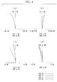
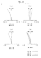
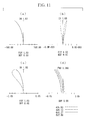
- (a) shows distortion
- (b) shows chromatic aberration of magnification
- (c) shows astigmatism
- (d) shows spherical aberration.
- a solid line shows the astigmatism in the sagittal image plane
- a chain line shows the astigmatism in the meridional image plane.
- the lens configuration of an endoscope objective lens according to Example 1 of this embodiment is shown in FIG. 3 .
- the front group includes, in sequence from the object side, a plano-concave lens (first lens) having a flat surface facing the object side, a biconcave lens (second lens), and a biconvex lens.
- the rear group includes, in sequence from the object side, a plano-convex lens having a flat surface facing the object side, a biconvex lens, and a negative meniscus lens having a concave surface facing the object side.
- the biconvex lens and the negative meniscus lens are combined.
- a focusing lens is a negative meniscus lens that has a concave surface facing the object side and that is inserted into or retracted from the optical path between the front group and the aperture stop.
- FIGS. 4 and 5 The aberration diagrams of the thus-configured endoscope objective lens according to this example, in the normal observation state and in the short-distance observation state, are shown in FIGS. 4 and 5 .
- Lens data surface number r d nd ⁇ d OBJ 30.0000 (d0) 1. 1 ⁇ 0.6238 1.88300 40.76 2 1.3366 0.5758 1. 3 (FS) ⁇ 0.0930 1. 4 -15.4125 0.4520 1.88300 40.76 5 3.0857 0.2676 1. 6 4.6793 1.0834 1.69895 30.13 7 -2.6759 0.5759 1. 8 -21.7597 (r8) 0.3899 1.88300 (GLA8) 40.76 9 -28.0944 (r9) 0.2651 1.
- the lens configuration of an endoscope objective lens according to Example 2 of this embodiment is shown in FIG. 6 .
- the front group includes, in sequence from the object side, a plano-concave lens (first lens) having a flat surface facing the object side, a negative meniscus lens (second lens) having a concave surface facing the object side, and a biconvex lens.
- the rear group includes two biconvex lenses and a negative meniscus lens having a concave surface facing the object side, and the biconvex lens on the image side and the negative meniscus lens are combined.
- the focusing lens is a negative meniscus lens that has a concave surface facing the object side and that is inserted into or retracted from the optical path between the front group and the aperture stop.
- FIGS. 7 and 8 The aberration diagrams of the thus-configured endoscope objective lens according to this example, in the normal observation state and in the short-distance observation state, are shown in FIGS. 7 and 8 .
- the lens configuration of an endoscope objective lens according to Example 3 of this embodiment is shown in FIG. 9 .
- the front group includes, in sequence from the object side, a plano-concave lens (first lens) having a flat surface facing the object side, and a positive meniscus lens (second lens) having a concave surface facing the object side.
- the rear group includes, in sequence from the object side, a positive meniscus lens having a concave surface facing the object side, a biconvex lens, and a negative meniscus lens having a concave surface facing the object side.
- the biconvex lens and the positive meniscus lens are combined.
- the focusing lens (sixth surface) is a plano-concave lens that has a flat surface facing the image side and that is inserted into or retracted from the optical path between the front group and the aperture stop.
- FIGS. 10 and 11 The aberration diagrams of the thus-configured endoscope objective lens according to this example, in the normal observation state and in the short-distance observation state, are shown in FIGS. 10 and 11 .
- Lens data surface number r d nd ⁇ d OBJ ⁇ 25.0000 1.
- (d0) 1 ⁇ 0.5353 1.88300 40.76 2 1.1348 0.5233 1.
- (FS) ⁇ 0.1337 1.
- the lens configuration of an endoscope objective lens according to Example 4 of this embodiment is shown in FIG. 12 .
- the front group includes, in sequence from the object side, a plano-concave lens (first lens) having a flat surface facing the object side, and a positive meniscus lens (second lens) having a concave surface facing the object side.
- the rear group includes, in sequence from the object side, two biconvex lenses and a negative meniscus lens having a concave surface facing the object side. In the rear group, the biconvex lens on the image side and the negative meniscus lens are combined.
- the focusing lens (sixth surface) is a negative meniscus lens that has a concave surface facing the object side and that is inserted into or retracted from the optical path between the front group and the aperture stop.
- FIGS. 13 and 14 The aberration diagrams of the thus-configured endoscope objective lens according to this example, in the normal observation state and in the short-distance observation state, are shown in FIGS. 13 and 14 .
- the lens configuration of an endoscope objective lens according to Example 5 of this embodiment is shown in FIG. 15 .
- the front group includes, in sequence from the object side, a plano-concave lens (first lens) having a flat surface facing the object side, a positive meniscus lens (second lens) having a concave surface facing the object side, and another positive meniscus lens having a concave surface facing the object side.
- the rear group includes, in sequence from the object side, two biconvex lenses and a negative meniscus lens having a concave surface facing the object side. In the rear group, the biconvex lens on the image side and the negative meniscus lens are combined.
- the focusing lens (eighth surface) has a negative meniscus lens that has a concave surface facing the object side and that is inserted into or retracted from the optical path between the front group and the aperture stop.
- FIGS. 16 and 17 The aberration diagrams of the thus-configured endoscope objective lens according to this example, in the normal observation state and in the short-distance observation state, are shown in FIGS. 16 and 17 .
- the lens configuration of an endoscope objective lens according to Example 6 of this embodiment is shown in FIG. 18 .
- the front group includes, in sequence from the object side, a plano-concave lens (first lens) having a flat surface facing the object side, a biconcave lens (second lens), and a positive meniscus lens having a concave surface facing the object side.
- An infrared cut filter, serving as an optical component E, is disposed between the plano-concave lens and the biconcave lens.
- the rear group includes, in sequence from the object side, a positive meniscus lens having a concave surface facing the object side, a negative meniscus lens having a concave surface facing the object side, two biconvex lenses, and a negative meniscus lens having a concave surface facing the object side.
- the positive meniscus lens on the object side and the negative meniscus lens are combined, and the biconvex lens on the image side and the negative meniscus lens are combined.
- a component corresponding to the twenty-third surface is an optical prism PL.
- the focusing lens (tenth surface) includes a negative meniscus lens that has a concave surface facing the object side and that is inserted into or retracted from the optical path between the front group and the aperture stop.
- FIGS. 19 and 20 The aberration diagrams of the thus-configured endoscope objective lens according to this example, in the normal observation state and in the short-distance observation state, are shown in FIGS. 19 and 20 .
- Lens data surface number r d nd ⁇ d OBJ ⁇ 19.7000 (dO) 1. 1 ⁇ 0.6278 1.88300 40.76 2 2.0066 0.6489 1. 3 (FS) ⁇ 0.0471 1. 4 (E) ⁇ 0.9417 1.51800 75.00 5 ⁇ 0.1473 1. 6 -36.9819 0.7582 1.88300 40.76 7 2.4930 0.4976 1. 8 -7.9998 0.6090 1.92286 18.90 9 -3.2815 0.5733 1.
- the lens configuration of an endoscope objective lens according to Example 7 of this embodiment is shown in FIG. 21 .
- the front group includes, in sequence from the object side, a plano-concave lens (first lens) having a flat surface facing the object side, a biconcave lens (second lens), and a biconvex lens.
- An infrared cut filter, serving as an optical component E, is disposed between the plano-concave lens and the biconcave lens.
- the rear group includes, in sequence from the object side, a positive meniscus lens having a concave surface facing the object side, a biconcave lens, a plano-convex lens having a flat surface facing the object plane, a biconvex lens, and a negative meniscus lens having a concave surface facing the object side.
- the positive meniscus lens on the object side and the biconcave lens are combined, and the biconvex lens on the image side and the negative meniscus lens are combined.
- the aperture stop may be disposed on the object side of the positive meniscus lens.
- the focusing lens (tenth surface) is a negative meniscus lens that has a concave surface facing the object side and that is inserted into or retracted from the optical path between the front group and the rear group.
- FIGS. 22 and 23 The aberration diagrams of the thus-configured endoscope objective lens according to this example, in the normal observation state and in the short-distance observation state, are shown in FIGS. 22 and 23 .
- Lens data surface number r d nd ⁇ d OBJ ⁇ 21.0000 (d0) 1. 1 ⁇ 0.6623 1.88300 40.76 2 1.9404 0.7629 1. 3 (FS) ⁇ 0.0497 1. 4 (E) ⁇ 0.9935 1.51800 75.00 5 ⁇ 0.1714 1. 6 -5.6800 0.3893 1.88300 40.76 7 3.4284 0.3104 1. 8 94.6110 0.7739 1.92286 18.90 9 -3.7903 0.6623 1.
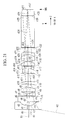
- the lens configuration of an endoscope objective lens according to Example 8 of this embodiment is shown in FIG. 24 .
- the front group includes, in sequence from the object side, a plano-concave lens (first lens) having a flat surface facing the object side, a biconcave lens (second lens), and a meniscus lens.
- the rear group includes two combined lenses.
- An infrared cut filter, serving as an optical component E, is disposed on the image side of these combined lenses.
- the focusing lens (ninth surface) is a plano-concave lens that has a flat surface facing the image side and that is inserted into or retracted from the optical path between the front group and the rear group.
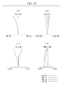
- FIGS. 25 and 26 The aberration diagrams of the thus-configured endoscope objective lens according to this example, in the normal observation state and in the short-distance observation state, are shown in FIGS. 25 and 26 .
- Lens data surface number r d nd ⁇ d OBJ 20.8000 (d0) 1. 1 ⁇ 0.6090 1.88300 40.76 2 1.7677 1.1244 1. 3 (FS) ⁇ 0.0459 1. 4 ⁇ 1.1218 1. 5 -6.7859 0.4546 1.88300 40.76 6 3.4679 0.3788 1. 7 -34.9131 0.7425 1.92286 18.90 8 -3.0411 0.6829 1. 9 -108.8804 (r9) 0.7184 1.51633 (GLA9) 64.14 10 ⁇ (r10) 0.9804 1.
- the values corresponding to Conditional Expressions (1) to (6) are shown in Table 1, and the specifications are shown in Table 2.
- FL is the focal length of the entire endoscope objective lens in the normal observation state
- 2 ⁇ is the angle of view (unit: deg)
- IH is the image height
- f_F is the focal length of the front group
- f_R is the focal length of the rear group
- fc is the focal length of the focusing lens
- ra is the radius of curvature of the object-side surface of the focusing lens
- rb is the radius of curvature of the image-side surface of the focusing lens
- r1b is the radius of curvature of the image-side surface of the first lens
- r2f is the radius of curvature of the object-side surface of the second lens.
- Example 2 Example 3
- Example 4 Example 5
- Example 6 Example 7
- Example 8 (1) -112.539 -77.056 -71.783 -57.003 -93.796 -68.158 -73.311 -210.874 fc/FL (2) 7.870 13.100 1.000 14.908 10.062 9.519 13.450 1.000 (rb+ra)/(rb-ra) (3) -21.760 -8.649 -34.994 -5.613 -14.164 -5.612 -7.140 -108.880 ra/FL (4) 0.840 0.456 0.662 0.745 0.700 0.897 0.491 0.587 (r2f+r1b)/(r2f-r1b) (5) -15.413 -2.964 -5.576 -7.276 -4.322 -36.982 -5.680 -6.786 r2f/FL (6) 1.337 1.108 1.135 1.065 0.763 2.007 1.940 1.768 r1 b/
Landscapes
- Physics & Mathematics (AREA)
- Health & Medical Sciences (AREA)
- Life Sciences & Earth Sciences (AREA)
- Optics & Photonics (AREA)
- Surgery (AREA)
- Engineering & Computer Science (AREA)
- General Physics & Mathematics (AREA)
- Biomedical Technology (AREA)
- Veterinary Medicine (AREA)
- Radiology & Medical Imaging (AREA)
- Nuclear Medicine, Radiotherapy & Molecular Imaging (AREA)
- Biophysics (AREA)
- Pathology (AREA)
- Heart & Thoracic Surgery (AREA)
- Medical Informatics (AREA)
- Molecular Biology (AREA)
- Animal Behavior & Ethology (AREA)
- General Health & Medical Sciences (AREA)
- Public Health (AREA)
- Astronomy & Astrophysics (AREA)
- Manufacturing & Machinery (AREA)
- Lenses (AREA)
- Endoscopes (AREA)
- Instruments For Viewing The Inside Of Hollow Bodies (AREA)
Abstract
Description
- The present invention relates to an endoscope objective lens and, more specifically, to an endoscope objective lens that has a focusing function.
- Conventionally, various focusing methods have been proposed for small, simple objective lenses suitable for endoscopes (for example, see
PTLs 1 to 3). InPTL 1, focusing is achieved by moving some lenses of an objective-lens optical system in the optical axis direction. InPTL 2, a wire is used to move a lens. InPTL 3, removable parallel plates are disposed near an aperture stop, and, by switching between parallel plates having different thicknesses, a shift of the focal position caused by a difference in the wavelength used is corrected. -
- {PTL 1} The Publication of Japanese Patent No.
4653823 - {PTL 2} The Publication of Japanese Patent No.
3251076 - {PTL 3} Japanese Unexamined Patent Application, Publication No.
2010-128459 - The conventional focusing methods, such as those disclosed in
PTLs 1 to 3, have the following problems. - In a typical focusing method, like that employed in
PTL 1, the position of image formation is corrected by moving, in the optical axis direction, a lens having refractive power. This method has a problem that deterioration in performance due to manufacturing errors tends to occur, for the following reasons. - The function of a focusing lens will be described from the standpoint of aberration correction. In an image-forming relationship for a certain object distance, a focusing lens, which is moved for focusing, shares the aberration correction with other lens elements. The ratio of this sharing is determined according to the refractive power, the surface shape, and the height and angle of rays, especially according to the refractive power. In this image-forming relationship, when manufacturing errors, particularly eccentricity errors, such as an error occurring in a direction perpendicular to the optical axis of the lens elements (shifting) or an error associated with tilting of the lens elements (tilting), occur, the sharing ratio of the aberration correction changes, causing asymmetric bokeh or the like, which makes the aberrations worse. The contribution ratio of the focusing lens and the other lens elements to the deterioration of the aberrations is determined according to, in particular, the refractive power, like the sharing ratio of the aberration correction. Hence, if a lens having higher refractive power becomes eccentric, the degree of deterioration of the aberrations tends to be greater.
- In addition, in the means for moving the lens disclosed in
PTL 2, a certain amount of slack has to be provided to facilitate sliding, which inevitably leads to eccentricity of the focusing lens. Furthermore, because the point of application of a force with the wire is displaced from the point of action of the lens, the focusing lens tends to become eccentric when moving on the optical axis in the focusing operation (during focusing). In particular, in recent years, with an increase in number of pixels of image sensors, the deterioration of aberrations due to manufacturing errors, such as eccentricity, has become more apparent. - In
PTL 3, the focal position is moved not by changing the working distance, but, when observation is performed at a predetermined working distance, by switching the parallel plates having different thicknesses to correct a shift in focal position due to the wavelength used. Therefore, the focal position can only be moved by a very small distance, small enough to correct an axial chromatic aberration of the objective lens. - The conventional focusing methods also have the following problems.
- Objective lenses of endoscopes are intended to achieve a wide angle of view with a simple configuration; hence, they have large negative distortion. If focusing is performed with such an objective lens, a problem occurs that the image plane is tilted in the minus (under) direction when the working distance changes from the long side to the short side.
- The present invention has been made in view of the above-described circumstances, and an object thereof is to provide an endoscope objective lens in which the aberrations are less susceptible to manufacturing errors and in which the variation in field curvature caused by focusing is small.
- To achieve the above-described object, the present invention employs the following solutions.
- The present invention provides an endoscope objective lens including: in sequence from the object side, a front group having negative refractive power, an aperture stop, and a rear group having positive refractive power; and a focusing lens that has negative refractive power and that can be inserted into or retracted from an optical path between the front group and the rear group. The focusing lens is inserted into the optical path in a normal observation state and is retracted from the optical path in a short-distance observation state, in which the working distance is smaller than that in the normal observation state.
- According to the present invention, the working distance in a state in which the focusing lens is retracted from the optical path is shorter than that in a state in which the focusing lens is inserted in the optical path and is disposed on the optical axis. Thus, when the focusing lens is inserted in the optical path, a relatively far object can be focused at a normal working distance. On the other hand, when the focusing lens is retracted from the optical path, a relatively near object can be focused at a working distance shorter than the normal working distance.
- The relationship between the presence/absence of the focusing lens in the optical path and the working distance is explained by the diverging effect of the focusing lens. More specifically, considering a change in position of the object point with respect to the image point depending on the presence/absence of the focusing lens, when the focusing lens is on the optical axis, because of the diverging effect thereof, focusing on a far object is achieved. On the other hand, when the focusing lens is not on the optical axis, because of the absence of the diverging effect thereof, focusing on a near object is achieved.
- In this case, the endoscope objective lens of the present invention, which employs the above-described focusing method, is characterized in that the aberrations are less susceptible to manufacturing errors. An eccentricity error occurring when the focusing lens is attached needs to be taken into consideration only in the normal observation state, in which the focusing lens is on the optical axis. In the short-distance observation state, in which the focusing lens is not on the optical axis, because the focusing lens is retracted from the optical path, deterioration in performance due to the eccentricity error does not occur. It is possible to employ a configuration in which the focusing lens is urged to a prescribed position of the frame when the focusing lens is located on the optical axis. Thus, the eccentricity error is less likely to occur.
- Note that, in the present invention, "focus" means to correct the movement of the focal position due to a change in working distance and to maintain the focal position constant. It means, for example, to bring the endoscope objective lens, which is focused on a far observation target, closer to the observation target and make it focus on the observation target, and it has the same meaning as "to bring something in focus" or "to focus on something".
- Furthermore, in the present invention, a lens group that is moved for focusing is called the "focusing lens".
- In the above-described invention, it is desirable that the following Conditional Expression (1) be satisfied.

where fc is the focal length of the focusing lens, and FL is the focal length of the entire system in the normal observation state. - Conditional Expression (1) relates to manufacturing errors and the amount of correction of the focus, and it defines the focal length of the focusing lens. When fc/FL is higher than or equal to -10, which is the upper limit of Conditional Expression (1), the degree of influence of the eccentricity error on the optical performance deterioration is large, which is undesirable. More specifically, even though the eccentricity error is the same, asymmetric bokeh etc. tend to occur. When fc/FL is lower than or equal to -230, which is the lower limit of Conditional Expression (1), the degree of influence of the eccentricity error on the optical performance deterioration is small. However, the amount of correction of the focus is small, which is undesirable. More specifically, the focusing range decreases.
- Note that this configuration desirably satisfies (1'), more desirably (1"), and most desirably (1"').


- In the above-described invention, it is desirable that the following Conditional Expressions (2) and (3) be satisfied, in addition to Conditional Expression (1).


where ra is the radius of curvature of an object-side surface of the focusing lens, and rb is the radius of curvature of an image-side surface of the focusing lens. - Conditional Expressions (2) and (3) relate to variation of aberrations caused by focusing and define the shape of the focusing lens. When (rb + ra)/(rb - ra) is lower than or equal to 0.7, which is the lower limit of Conditional Expression (2), or when ra/FL is lower than or equal to -120, which is the lower limit of Conditional Expression (3), the image plane is tilted in the minus (under) direction in the short-distance observation state, which is undesirable. When (rb + ra)/(rb - ra) is higher than or equal to 20, which is the upper limit of Conditional Expression (2), or when ra/FL is higher than or equal to -3, which is upper limit of Conditional Expression (3), the difference (astigmatic difference) between the sagittal image plane and the meridional image plane is large, which is undesirable.
- Note that this configuration desirably satisfies (3'), more desirably (3"), and most desirably (3"'), as follows:


- In the above-described invention, it is desirable that Conditional Expressions (1) to (3) be satisfied; the front group include, in sequence from the object side, a first lens having a concave surface facing the image side, and a second lens having a concave surface facing the object side; and the following Conditional Expressions (4), (5), and (6) be satisfied.


where r2f is the radius of curvature of an object-side surface of the second lens, and r1b is the radius of curvature of an image-side surface of the first lens. - Conditional Expressions (4), (5), and (6) relate to reduction in size of the front group and define the lens shape of the lens end portion. When (r2f + r1b)/(r2f - r1b) is lower than or equal to 1, which is the upper limit of Conditional Expression (4), when r2f/FL is lower than or equal to -50, which is the lower limit of Conditional Expression (5), or when r1b/FL is lower than or equal to 0.5, which is the lower limit of Conditional Expression (6), the lens diameter of the front group tends to increase, which is undesirable. It is also disadvantageous for increasing the angle of view. When (r2f + r1b)/(r2f - r1b) is higher than or equal to 0.25, which is the lower limit of Conditional Expression (4), when r2f/FL is higher than or equal to -2, which is the upper limit of Conditional Expression (5), or when r1b/FL is higher than or equal to 3, which is the upper limit of Conditional Expression (6), although it is advantageous for reducing the lens diameter of the front group, high-order off-axis aberrations tend to occur, which is undesirable. Note that, an optical filter, such as an infrared cut filter, may be disposed between the first lens and the second lens.
- Note that this configuration desirably satisfies (5'), and more desirably (5"), as follows:


- Furthermore, this configuration desirably satisfies (6'), more desirably (6"), and most desirably (6"'), as follows:


- In the above-described invention, it is desirable that the focusing lens be a molded lens.
- In the present invention, mainly, a meniscus lens is used as the focusing lens. By using a molded lens as the meniscus lens constituting the focusing lens, the focusing lens can be manufactured easily and at low cost, compared with a case where the meniscus lens is formed by polishing.
- In the above-described configuration, it is more desirable to provide an arm member that supports the focusing lens and moves the focusing lens between an inserted position where the focusing lens is inserted in the optical path and a retracted position where the focusing lens is retracted from the optical path, the arm member being molded integrally with the focusing lens.
- With this configuration, a frame member for the arm member to support the focusing lens is unnecessary, and a space for accommodating the retracted focusing lens can be reduced.
- The present invention provides the advantages that aberrations are less susceptible to manufacturing errors and that variations in field curvature caused by focusing can be reduced.
-
- {
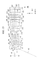
FIG. 1} FIG. 1 includes lens cross-sections showing the overall configuration of an endoscope objective lens according to an embodiment of the present invention, showing (a) a normal observation state in which a focusing lens is inserted into an optical path and (b) a short-distance observation state in which the focusing lens is retracted from the optical path. - {
FIG. 2} FIG. 2 includes (a) a front view and (b) a side view, respectively, showing an example arm member for supporting the focusing lens. - {
FIG. 3} FIG. 3 is a lens cross-section showing the overall configuration (in the normal observation state) of an endoscope objective lens according to Example 1 of the present invention. - {
FIG. 4} FIG. 4 includes aberration diagrams showing (a) distortion, (b) chromatic aberration of magnification, (c) astigmatism, and (d) spherical aberration, respectively, of the endoscope objective lens, in the normal observation state, according to Example 1 of the present invention. - {
FIG. 5} FIG. 5 includes aberration diagrams showing (a) distortion, (b) chromatic aberration of magnification, (c) astigmatism, and (d) spherical aberration, respectively, of the endoscope objective lens, in the short-distance observation state, according to Example 1 of the present invention. - {
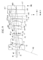
FIG. 6} FIG. 6 is a lens cross-section showing the overall configuration (in the normal observation state) of an endoscope objective lens according to Example 2 of the present invention. - {
FIG. 7} FIG. 7 includes aberration diagrams showing (a) distortion, (b) chromatic aberration of magnification, (c) astigmatism, and (d) spherical aberration, respectively, of the endoscope objective lens, in the normal observation state, according to Example 2 of the present invention. - {
FIG. 8} FIG. 8 includes aberration diagrams showing (a) distortion, (b) chromatic aberration of magnification, (c) astigmatism, and (d) spherical aberration, respectively, of the endoscope objective lens, in the short-distance observation state, according to Example 2 of the present invention. - {
FIG. 9} FIG. 9 is a lens cross-section showing the overall configuration (in the normal observation state) of an endoscope objective lens according to Example 3 of the present invention. - {
FIG. 10} FIG. 10 includes aberration diagrams showing (a) distortion, (b) chromatic aberration of magnification, (c) astigmatism, and (d) spherical aberration, respectively, of the endoscope objective lens, in the normal observation state, according to Example 3 of the present invention. - {
FIG. 11} FIG. 11 includes aberration diagrams showing (a) distortion, (b) chromatic aberration of magnification, (c) astigmatism, and (d) spherical aberration, respectively, of the endoscope objective lens, in the short-distance observation state, according to Example 3 of the present invention. - {
FIG. 12} FIG. 12 is a lens cross-section showing the overall configuration (in the normal observation state) of an endoscope objective lens according to Example 4 of the present invention. - {
FIG. 13} FIG. 13 includes aberration diagrams showing (a) distortion, (b) chromatic aberration of magnification, (c) astigmatism, and (d) spherical aberration, respectively, of the endoscope objective lens, in the normal observation state, according to Example 4 of the present invention. - {
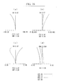
FIG. 14} FIG. 14 includes aberration diagrams showing (a) distortion, (b) chromatic aberration of magnification, (c) astigmatism, and (d) spherical aberration, respectively, of the endoscope objective lens, in the short-distance observation state, according to Example 4 of the present invention. - {
FIG. 15} FIG. 15 is a lens cross-section showing the overall configuration (in the normal observation state) of an endoscope objective lens according to Example 5 of the present invention. - {
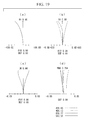
FIG. 16} FIG. 16 includes aberration diagrams showing (a) distortion, (b) chromatic aberration of magnification, (c) astigmatism, and (d) spherical aberration, respectively, of the endoscope objective lens, in the normal observation state, according to Example 5 of the present invention. - {
FIG. 17} FIG. 17 includes aberration diagrams showing (a) distortion, (b) chromatic aberration of magnification, (c) astigmatism, and (d) spherical aberration, respectively, of the endoscope objective lens, in the short-distance observation state, according to Example 5 of the present invention. - {
FIG. 18} FIG. 18 is a lens cross-section showing the overall configuration (in the normal observation state) of an endoscope objective lens according to Example 6 of the present invention. - {
FIG. 19} FIG. 19 includes aberration diagrams showing (a) distortion, (b) chromatic aberration of magnification, (c) astigmatism, and (d) spherical aberration, respectively, of the endoscope objective lens, in the normal observation state, according to Example 6 of the present invention. - {
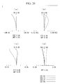
FIG. 20} FIG. 20 includes aberration diagrams showing (a) distortion, (b) chromatic aberration of magnification, (c) astigmatism, and (d) spherical aberration, respectively, of the endoscope objective lens, in the short-distance observation state, according to Example 6 of the present invention. - {
FIG. 21} FIG. 21 is a lens cross-section showing the overall configuration (in the normal observation state) of an endoscope objective lens according to Example 7 of the present invention. - {
FIG. 22} FIG. 22 includes aberration diagrams showing (a) distortion, (b) chromatic aberration of magnification, (c) astigmatism, and (d) spherical aberration, respectively, of the endoscope objective lens, in the normal observation state, according to Example 7 of the present invention. - {
FIG. 23} FIG. 23 includes aberration diagrams showing (a) distortion, (b) chromatic aberration of magnification, (c) astigmatism, and (d) spherical aberration, respectively, of the endoscope objective lens, in the short-distance observation state, according to Example 7 of the present invention. - {
FIG. 24} FIG. 24 is a lens cross-section showing the overall configuration (in the normal observation state) of an endoscope objective lens according to Example 8 of the present invention. - {
FIG. 25} FIG. 25 includes aberration diagrams showing (a) distortion, (b) chromatic aberration of magnification, (c) astigmatism, and (d) spherical aberration, respectively, of the endoscope objective lens, in the normal observation state, according to Example 8 of the present invention. - {
FIG. 26} FIG. 26 includes aberration diagrams showing (a) distortion, (b) chromatic aberration of magnification, (c) astigmatism, and (d) spherical aberration, respectively, of the endoscope objective lens, in the short-distance observation state, according to Example 8 of the present invention. - Referring to
FIGS. 1 and2 , anendoscope objective lens 1 according to an embodiment of the present invention will be described below. - As illustrated in
FIG. 1(a) , theendoscope objective lens 1 according to this embodiment includes, in sequence from the object side, a front group GF, an aperture stop AS, and a rear group GR. The endoscopeobjective lens 1 further includes a focusing lens Lf that is provided in such a manner that it can be inserted into or retracted from an optical path between the front group GF and the rear group GR. - In the figures, reference sign OBJ denotes an object plane, reference sign IMG denotes an image plane, reference sign R1 denotes an axial marginal ray, and reference sign R2 denotes a principal ray at the maximum angle of view.
- The front group GF includes, in sequence from the object side, a plano-concave lens (first lens) L1 having a flat surface facing the object side, a biconcave lens (second lens) L2, and a biconvex lens L3. The front group GF has negative refractive power.
- The rear group GR includes, in sequence from the object side, a plano-convex lens L4 having a flat surface facing the object side, a biconvex lens L5, and a negative meniscus lens L6 having a concave surface facing the object side. The rear group GR has positive refractive power. The biconvex lens L5 and the negative meniscus lens L6 are combined.
- Note that the number and shape of the lenses constituting the front group GF and the rear group GR are not limited to those presented above and may be appropriately changed.
- The endoscope
objective lens 1 further optionally includes a flare stop FS, an optical component E, such as an infrared cut filter or an optical low-pass filter, a CCD cover glass G1, and a CCD chip sealing glass G2. - The focusing lens Lf has negative refractive power and is, preferably, a meniscus lens. In the normal observation state, the focusing lens Lf is disposed in the optical path such that the concave surface thereof faces the object side and such that the optical axis thereof is aligned with the optical axis of the endoscope
objective lens 1, as illustrated inFIG. 1(a) . On the other hand, in the short-distance observation state, the focusing lens Lf is retracted from the optical path, as illustrated inFIG. 1(b) . In the short-distance observation state, in which the focusing lens Lf does not exist in the optical path, a working distance WD of the endoscopeobjective lens 1 is smaller than that in the normal observation state. Hence, the focal point moves in a direction toward the first lens L1, enabling short-distance observation. - The endoscope
objective lens 1 satisfies the following Conditional Expressions (1) to (6).





where fc is the focal length of the focusing lens Lf, FL is the focal length of the entireendoscope objective lens 1 with the focusing lens Lf inserted into the optical path, ra is the radius of curvature of an object-side surface of the focusing lens Lf, rb is the radius of curvature of the image-side surface of the focusing lens Lf, r2f is the radius of curvature of the object-side surface of the second lens L2, and r1b is the radius of curvature of the image-side surface of the first lens L1. -
FIG. 2(a) shows an example driving mechanism that moves the focusing lens Lf between an inserted position (shown by a solid line) and a retracted position (shown by a two-dot chain line). The driving mechanism has anarm member 2 at one end, which supports the focusing lens Lf, and a motor (not shown) that rotates the other end of thearm member 2 to swing the focusing lens Lf.Reference numeral 3 denotes a lens barrel accommodating the endoscopeobjective lens 1. - The focusing lens Lf is a molded lens, and the
arm member 2 and the focusing lens Lf are integrally molded.FIG. 2(b) is a diagram showing the integrally molded focusing lens Lf andarm member 2, as viewed from the side. By molding the focusing lens Lf and thearm member 2 integrally, a frame member for supporting the focusing lens Lf does not need to be provided at the outer circumference of the focusing lens Lf, and hence, the diameter can be reduced. - In the thus-configured
endoscope objective lens 1, the aberrations are less susceptible to manufacturing errors, and the variation in field curvature caused by focusing is small. Hence, it is possible to stably obtain high-quality images. - Next, examples of the above-described endoscope objective lens according to this embodiment will be described below, with reference to
FIGS. 3 to 26 . - In lens data presented in the respective examples, r is the radius of curvature, d is the surface distance, nd is the refractive index at the d-line, νd is the Abbe number at the d-line, OBJ is the object plane, and IMG is the image plane. The lens data is data in the normal observation state, including the focusing lens inserted into the optical path. Numerical values that differ between the normal observation state and the short-distance observation state (e.g., the working distance d0; the radius of curvatures ri and ri + 1 of i-th and i+1-th surfaces (corresponding to the lens surface of the focusing lens); and the refractive index and Abbe number of a medium GLAi filling the space between the i-th and i+1-th surfaces (when the medium is air, it will be indicated "air") will be shown in Miscellaneous Data. The surface numbers corresponding to the aperture stop, the flare stop, the optical component, the CCD cover glass, and the CCD chip sealing glass are accompanied by reference numerals AS, FS, E, G1, and G2, respectively.
- The lens cross-sections to be referred to show the lens configurations in the normal state, including the focusing lens inserted into the optical path. In the lens cross-sections, the optical axis direction of the endoscope objective lens is assumed to be direction Z, and the image height direction is assumed to be direction Y. Furthermore, reference numeral R1 denotes an axial marginal ray, and reference numeral R2 denotes a principal ray at the maximum angle of view.
- In the aberration diagrams to be referred to, (a) shows distortion, (b) shows chromatic aberration of magnification, (c) shows astigmatism, and (d) shows spherical aberration. In (c), a solid line shows the astigmatism in the sagittal image plane, and a chain line shows the astigmatism in the meridional image plane.
- The lens configuration of an endoscope objective lens according to Example 1 of this embodiment is shown in
FIG. 3 . - In this example, the front group includes, in sequence from the object side, a plano-concave lens (first lens) having a flat surface facing the object side, a biconcave lens (second lens), and a biconvex lens. The rear group includes, in sequence from the object side, a plano-convex lens having a flat surface facing the object side, a biconvex lens, and a negative meniscus lens having a concave surface facing the object side. In the rear group, the biconvex lens and the negative meniscus lens are combined.
- A focusing lens (eighth surface) is a negative meniscus lens that has a concave surface facing the object side and that is inserted into or retracted from the optical path between the front group and the aperture stop.
- The aberration diagrams of the thus-configured endoscope objective lens according to this example, in the normal observation state and in the short-distance observation state, are shown in
FIGS. 4 and5 .Lens data surface number r d nd νd OBJ ∞ 30.0000 (d0) 1. 1 ∞ 0.6238 1.88300 40.76 2 1.3366 0.5758 1. 3 (FS) ∞ 0.0930 1. 4 -15.4125 0.4520 1.88300 40.76 5 3.0857 0.2676 1. 6 4.6793 1.0834 1.69895 30.13 7 -2.6759 0.5759 1. 8 -21.7597 (r8) 0.3899 1.88300 (GLA8) 40.76 9 -28.0944 (r9) 0.2651 1. 10 (AS) ∞ 1.1697 1. 11 ∞ 0.7390 1.69680 55.53 12 -3.1521 0.0312 1. 13 (FS) ∞ 0.0468 1. 14 4.2780 1.2638 1.65160 58.55 15 -1.9266 0.4679 1.92286 18.90 16 -5.2633 0.0780 1. 17 (FS) ∞ 0.0468 1. 18 (E) ∞ 0.9357 1.51800 75.00 19 ∞ 0.6263 1 20 (G1) ∞ 0.7798 1.51633 64.14 21 ∞ 0.0156 1.51300 63.01 22 (G2) ∞ 0.7798 1.50600 60.00 IMG ∞ 0. Miscellaneous Data normal observation state short-distance observation state d0 30.0000 8.7000 r8 -21.75966 ∞ r9 -28.09439 ∞ GLA8 nd:1.88300 air νd:40.76 - The lens configuration of an endoscope objective lens according to Example 2 of this embodiment is shown in
FIG. 6 . - In this example, the front group includes, in sequence from the object side, a plano-concave lens (first lens) having a flat surface facing the object side, a negative meniscus lens (second lens) having a concave surface facing the object side, and a biconvex lens. The rear group includes two biconvex lenses and a negative meniscus lens having a concave surface facing the object side, and the biconvex lens on the image side and the negative meniscus lens are combined.
- The focusing lens (eighth surface) is a negative meniscus lens that has a concave surface facing the object side and that is inserted into or retracted from the optical path between the front group and the aperture stop.
- The aberration diagrams of the thus-configured endoscope objective lens according to this example, in the normal observation state and in the short-distance observation state, are shown in
FIGS. 7 and8 .Lens data surface number r d nd νd OBJ ∞ 24.0000 (d0) 1. 1 ∞ 0.5069 1.88300 40.76 2 1.1077 0.4562 1. 3 (FS) ∞ 0.2661 1. 4 -2.9644 0.7604 1.92286 18.90 5 -5.5764 0.1267 1. 6 10.5406 0.6970 1.84666 23.78 7 -4.7006 0.4623 1. 8 -8.6485 (r8) 0.3168 1.88300 (GLA8) 40.76 9 -10.0780 (r9) 0.0887 1. 10 (AS) ∞ 1.0139 1. 11 23.8606 0.7604 1.65160 58.55 12 -2.8896 0.0380 1. 13 (FS) ∞ 0.0887 1. 14 3.3217 1.0773 1.58913 61.14 15 -2.1127 0.4436 1.92286 18.90 16 -6.0136 0.1267 1. 17 (FS) ∞ 0.0380 1. 18 (E) ∞ 0.7604 1.51800 75.00 19 ∞ 0.5235 1. 20 (G1) ∞ 0.8872 1.51633 64.14 21 ∞ 0.0127 1.51300 63.01 22 (G2) ∞ 0.8872 1.50600 60.00 IMG ∞ 0. Miscellaneous Data normal observation state short-distance observation state d0 24.0000 7.2000 r8 -8.64846 ∞ r9 -10.07804 ∞ GLA8 nd:1.88300 air νd:40.76 - The lens configuration of an endoscope objective lens according to Example 3 of this embodiment is shown in
FIG. 9 . - In this example, the front group includes, in sequence from the object side, a plano-concave lens (first lens) having a flat surface facing the object side, and a positive meniscus lens (second lens) having a concave surface facing the object side. The rear group includes, in sequence from the object side, a positive meniscus lens having a concave surface facing the object side, a biconvex lens, and a negative meniscus lens having a concave surface facing the object side. In the rear group, the biconvex lens and the positive meniscus lens are combined.
- The focusing lens (sixth surface) is a plano-concave lens that has a flat surface facing the image side and that is inserted into or retracted from the optical path between the front group and the aperture stop.
- The aberration diagrams of the thus-configured endoscope objective lens according to this example, in the normal observation state and in the short-distance observation state, are shown in
FIGS. 10 and11 .Lens data surface number r d nd νd OBJ ∞ 25.0000 1. (d0) 1 ∞ 0.5353 1.88300 40.76 2 1.1348 0.5233 1. 3 (FS) ∞ 0.1337 1. 4 -5.5758 1.2513 2.00330 28.27 5 -2.5855 0.5342 1. 6 -34.9936 (r6) 0.3156 1.48749 (GLA6) 70.23 7 ∞ 0.0669 1. (r7) 8 (AS) ∞ 0.9056 1. 9 -7.1090 0.6044 1.88300 40.76 10 -2.2737 0.0439 1. 11 3.6328 0.9594 1.69680 55.53 12 -1.7382 0.4014 1.92286 18.90 13 -7.3173 0.1338 1. 14 (E) ∞ 0.4148 1.51633 64.14 15 ∞ 0.5432 1. 16 (G1) ∞ 0.8029 1.51633 64.14 17 ∞ 0.0134 1.51300 63.01 18 (G2) ∞ 0.8029 1.50600 60.00 IMG ∞ 0. Miscellaneous Data normal observation state short-distance observation state d0 25.0000 7.5000 r6 -34.99361 ∞ r7 ∞ ∞ GLA6 nd:1.48749 air ∞d:70.23 - The lens configuration of an endoscope objective lens according to Example 4 of this embodiment is shown in
FIG. 12 . - In this example, the front group includes, in sequence from the object side, a plano-concave lens (first lens) having a flat surface facing the object side, and a positive meniscus lens (second lens) having a concave surface facing the object side. The rear group includes, in sequence from the object side, two biconvex lenses and a negative meniscus lens having a concave surface facing the object side. In the rear group, the biconvex lens on the image side and the negative meniscus lens are combined.
- The focusing lens (sixth surface) is a negative meniscus lens that has a concave surface facing the object side and that is inserted into or retracted from the optical path between the front group and the aperture stop.
- The aberration diagrams of the thus-configured endoscope objective lens according to this example, in the normal observation state and in the short-distance observation state, are shown in
FIGS. 13 and14 .Lens data surface number r d nd νd OBJ ∞ 24.0000 (d0) 1. 1 ∞ 0.5174 1.88300 40.76 2 1.0649 0.5156 1. 3 (FS) ∞ 0.1203 1. 4 -7.2757 1.0012 1.92286 18.90 5 -3.2252 0.5821 1. 6 -5.6126 (r6) 0.2546 1.92286 (GLA6) 18.90 7 -6.4197 (r7) 0.0647 1. 8 (AS) ∞ 0.7736 1. 9 23.1334 0.6333 1.88300 40.76 10 -2.6059 0.0569 1. 11 4.3225 0.9048 1.65160 58.55 12 -1.6704 0.3881 1.92286 18.90 13 -6.5845 0.1294 1. 14 (E) ∞ 0.4010 1.51633 64.14 15 ∞ 0.7783 1. 16 ∞ 0.7761 1.51633 64.14 17 (G1) ∞ 0.0129 1.51300 63.01 18 ∞ 0.7761 1.50600 60.00 19 (G2) ∞ 0. 1. IMG ∞ 0. Miscellaneous Data normal observation state short-distance observation state d0 24.0000 7.3000 r6 -5.61259 ∞ r7 -6.41971 GLA6 nd:1.92286 air νd:18.90 - The lens configuration of an endoscope objective lens according to Example 5 of this embodiment is shown in
FIG. 15 . - In this example, the front group includes, in sequence from the object side, a plano-concave lens (first lens) having a flat surface facing the object side, a positive meniscus lens (second lens) having a concave surface facing the object side, and another positive meniscus lens having a concave surface facing the object side. The rear group includes, in sequence from the object side, two biconvex lenses and a negative meniscus lens having a concave surface facing the object side. In the rear group, the biconvex lens on the image side and the negative meniscus lens are combined.
- The focusing lens (eighth surface) has a negative meniscus lens that has a concave surface facing the object side and that is inserted into or retracted from the optical path between the front group and the aperture stop.
- The aberration diagrams of the thus-configured endoscope objective lens according to this example, in the normal observation state and in the short-distance observation state, are shown in
FIGS. 16 and17 .Lens data surface number r d nd νd OBJ ∞ 24.0000 (dO) 1. 1 ∞ 0.2516 1.88300 40.76 2 0.7628 0.6775 1. 3 (FS) ∞ 0.0841 1. 4 -4.3220 0.3485 1.88300 40.76 5 -2.3317 0.2914 1. 6 -1.5290 0.4841 1.88300 40.76 7 -1.3410 0.2509 1. 8 -14.1643 0.3607 1.88300 40.76 (r8) (GLA8) 9 -17.2905 (r9) 0.1895 1. 10 (AS) ∞ 0.5222 1. 11 2.1889 0.6225 1.51823 58.90 12 -4.1376 0.3633 1. 13 5.2905 1.0154 1.48749 70.23 14 -1.1207 0.3145 1.92286 18.90 15 -2.9312 0.0629 1. 16 (E) ∞ 0.3899 1.51400 75.00 17 ∞ 0.0377 1. 18 (E) ∞ 0.3899 1.52300 58.50 19 ∞ 0.5060 1. 20 (G1) ∞ 0.6289 1.51633 64.14 21 ∞ 0.0126 1.51300 63.01 22 (G2) ∞ 0.3773 1.50600 60.00 IMG ∞ 0. Miscellaneous Data normal observation state short-distance observation state d0 24.0000 7.0000 r8 -14.16429 ∞ r9 -17.29047 ∞ GLA8 nd:1.88300 air νd:40.76 - The lens configuration of an endoscope objective lens according to Example 6 of this embodiment is shown in
FIG. 18 . - In this example, the front group includes, in sequence from the object side, a plano-concave lens (first lens) having a flat surface facing the object side, a biconcave lens (second lens), and a positive meniscus lens having a concave surface facing the object side. An infrared cut filter, serving as an optical component E, is disposed between the plano-concave lens and the biconcave lens. The rear group includes, in sequence from the object side, a positive meniscus lens having a concave surface facing the object side, a negative meniscus lens having a concave surface facing the object side, two biconvex lenses, and a negative meniscus lens having a concave surface facing the object side. In the rear group, the positive meniscus lens on the object side and the negative meniscus lens are combined, and the biconvex lens on the image side and the negative meniscus lens are combined. A component corresponding to the twenty-third surface is an optical prism PL.
- The focusing lens (tenth surface) includes a negative meniscus lens that has a concave surface facing the object side and that is inserted into or retracted from the optical path between the front group and the aperture stop.
- The aberration diagrams of the thus-configured endoscope objective lens according to this example, in the normal observation state and in the short-distance observation state, are shown in
FIGS. 19 and20 .Lens data surface number r d nd νd OBJ ∞ 19.7000 (dO) 1. 1 ∞ 0.6278 1.88300 40.76 2 2.0066 0.6489 1. 3 (FS) ∞ 0.0471 1. 4 (E) ∞ 0.9417 1.51800 75.00 5 ∞ 0.1473 1. 6 -36.9819 0.7582 1.88300 40.76 7 2.4930 0.4976 1. 8 -7.9998 0.6090 1.92286 18.90 9 -3.2815 0.5733 1. 10 -5.6123 (r10) 0.6240 1.51633 (GLA10) 64.14 11 -6.9299 (r11) 1.4464 1. 12 (AS) ∞ 0.0471 1. 13 -15.5514 0.8969 1.84666 23.78 14 -1.3261 0.3924 2.00330 28.27 15 -4.7763 0.0314 1. 16 (FS) ∞ 0.0471 1. 17 22.5970 0.8137 1.48749 70.23 18 -2.3801 0.0471 1. 19 15.6900 0.9006 1.58913 61.14 20 -2.0398 0.4708 1.92286 18.90 21 -5.9644 0.4377 1. 22 (FS) ∞ 0.0471 1. 23 (PL) ∞ 5.1529 1.72916 54.68 24 ∞ 1.2712 1. IMG ∞ 0. Miscellaneous Data normal observation state short-distance observation state d0 19.7000 4.9000 r10 -5.61226 ∞ r11 -6.92989 ∞ GLA10 nd:1.51633 air νd:64.14 - The lens configuration of an endoscope objective lens according to Example 7 of this embodiment is shown in
FIG. 21 . - In this example, the front group includes, in sequence from the object side, a plano-concave lens (first lens) having a flat surface facing the object side, a biconcave lens (second lens), and a biconvex lens. An infrared cut filter, serving as an optical component E, is disposed between the plano-concave lens and the biconcave lens. The rear group includes, in sequence from the object side, a positive meniscus lens having a concave surface facing the object side, a biconcave lens, a plano-convex lens having a flat surface facing the object plane, a biconvex lens, and a negative meniscus lens having a concave surface facing the object side. In the rear group, the positive meniscus lens on the object side and the biconcave lens are combined, and the biconvex lens on the image side and the negative meniscus lens are combined. The aperture stop may be disposed on the object side of the positive meniscus lens.
- The focusing lens (tenth surface) is a negative meniscus lens that has a concave surface facing the object side and that is inserted into or retracted from the optical path between the front group and the rear group.
- The aberration diagrams of the thus-configured endoscope objective lens according to this example, in the normal observation state and in the short-distance observation state, are shown in
FIGS. 22 and23 .Lens data surface number r d nd νd OBJ ∞ 21.0000 (d0) 1. 1 ∞ 0.6623 1.88300 40.76 2 1.9404 0.7629 1. 3 (FS) ∞ 0.0497 1. 4 (E) ∞ 0.9935 1.51800 75.00 5 ∞ 0.1714 1. 6 -5.6800 0.3893 1.88300 40.76 7 3.4284 0.3104 1. 8 94.6110 0.7739 1.92286 18.90 9 -3.7903 0.6623 1. 10 -7.1402 (r10) 0.4967 1.88300 (GLA10) 40.76 11 -8.2872 (r11) 1.5233 1. 12 (FS) ∞ 0.0497 1. 13 -63.3015 0.8867 1.92286 18.90 14 -2.8981 0.4139 2.00330 28.27 15 8.3149 0.0331 1. 16 (AS) ∞ 0.0497 1. 17 ∞ 0.7858 1.48749 70.23 18 -2.3952 0.0828 1. 19 3.6431 1.2605 1.48749 70.23 20 -1.8890 0.4967 1.92286 18.90 21 -2.9467 0.7933 1. 22 (FS) ∞ 0.0497 1. 23 (E) ∞ 0.0546 1.53000 56.00 24 (PL) ∞ 5.9741 1.72916 54.68 25 ∞ 0.0166 1.51000 64.00 26 (G2) ∞ 0.8279 1.61062 50.49 27 ∞ 0.3312 1. IMG ∞ 0. Miscellaneous Data normal observation state short-distance observation state d0 21.0000 5.1000 r10 -7.14017 ∞ r11 -8.28720 ∞ GLA10 nd:1.88300 air νd:40.76 - The lens configuration of an endoscope objective lens according to Example 8 of this embodiment is shown in
FIG. 24 . - In this example, the front group includes, in sequence from the object side, a plano-concave lens (first lens) having a flat surface facing the object side, a biconcave lens (second lens), and a meniscus lens. The rear group includes two combined lenses. An infrared cut filter, serving as an optical component E, is disposed on the image side of these combined lenses.
- The focusing lens (ninth surface) is a plano-concave lens that has a flat surface facing the image side and that is inserted into or retracted from the optical path between the front group and the rear group.
- The aberration diagrams of the thus-configured endoscope objective lens according to this example, in the normal observation state and in the short-distance observation state, are shown in
FIGS. 25 and26 .Lens data surface number r d nd νd OBJ ∞ 20.8000 (d0) 1. 1 ∞ 0.6090 1.88300 40.76 2 1.7677 1.1244 1. 3 (FS) ∞ 0.0459 1. 4 ∞ 1.1218 1. 5 -6.7859 0.4546 1.88300 40.76 6 3.4679 0.3788 1. 7 -34.9131 0.7425 1.92286 18.90 8 -3.0411 0.6829 1. 9 -108.8804 (r9) 0.7184 1.51633 (GLA9) 64.14 10 ∞ (r10) 0.9804 1. 11 (AS) ∞ 0.1515 1. 12 -10.7619 0.8940 1.53172 48.84 13 -1.6970 0.3788 2.00330 28.27 14 -2.2508 0.0758 1. 15 5.4666 0.9092 1.48749 70.23 16 -2.1303 0.4546 1.92286 18.90 17 -3.6797 0.2995 1. 18 (E) ∞ 0.9983 1.51633 64.14 19 ∞ 1.2678 1. 20 (FS) ∞ 0.0399 1. 21 (G1) ∞ 2.3161 1.51633 64.14 22 (G2) ∞ 1.4975 1.61062 50.49 IMG ∞ 0. Miscellaneous Data normal observation state short-distance observation state d0 20.8000 4.7100 r9 -108.8804 ∞ r10 ∞ ∞ GLA9 nd:1.51633 air vd:64.14 - Regarding the endoscope objective lens according to Examples 1 to 8 of this embodiment, the values corresponding to Conditional Expressions (1) to (6) are shown in Table 1, and the specifications are shown in Table 2. In Tables 1 and 2, FL is the focal length of the entire endoscope objective lens in the normal observation state, 2ω is the angle of view (unit: deg), IH is the image height, f_F is the focal length of the front group, f_R is the focal length of the rear group, fc is the focal length of the focusing lens, ra is the radius of curvature of the object-side surface of the focusing lens, rb is the radius of curvature of the image-side surface of the focusing lens, r1b is the radius of curvature of the image-side surface of the first lens, and r2f is the radius of curvature of the object-side surface of the second lens.
{Table 1} Conditional Expression Example 1 Example 2 Example 3 Example 4 Example 5 Example 6 Example 7 Example 8 (1) -112.539 -77.056 -71.783 -57.003 -93.796 -68.158 -73.311 -210.874 fc/FL (2) 7.870 13.100 1.000 14.908 10.062 9.519 13.450 1.000 (rb+ra)/(rb-ra) (3) -21.760 -8.649 -34.994 -5.613 -14.164 -5.612 -7.140 -108.880 ra/FL (4) 0.840 0.456 0.662 0.745 0.700 0.897 0.491 0.587 (r2f+r1b)/(r2f-r1b) (5) -15.413 -2.964 -5.576 -7.276 -4.322 -36.982 -5.680 -6.786 r2f/FL (6) 1.337 1.108 1.135 1.065 0.763 2.007 1.940 1.768 r1 b/FL {Table 2} Example 1 Example 2 Example 3 Example 4 Example 5 Example 6 Example 7 Example 8 FL normal observation state 1.000 1.000 1.000 1.000 1.000 1.000 1.000 1.000 short-distance observation state 0.987 0.990 0.983 0.986 0.983 0.994 0.996 0.969 effective Fno. normal observation state 3.009 3.412 3.415 3.326 3.592 3.776 3.763 3.517 short-distance observation state 3.010 3.412 3.417 3.328 3.593 3.780 3.765 3.520 2ω normal observation state 137.6 137.6 140.4 140.7 132.6 133.7 161.0 130.1 short-distance observation state 138.7 137.7 141.0 140.9 132.0 132.3 159.0 135.4 IH 1.001 0.963 1.028 0.993 0.966 0.982 1.037 0.949 f_F -3.901 -3.160 -4.783 -2.307 -5.730 -1.648 -1.915 -2.424 f_R 2.609 2.467 2.156 2.034 2.678 3.309 3.469 3.476 fc -112.539 -77.056 -71.783 -57.003 -93.796 -68.158 -73.311 -210.874 ra -21.7597 -8.6485 -34.9936 -5.6126 -14.1643 -5.6123 -7.1402 -108.8804 rb -28.0944 -10.078 ∞ -6.4197 -17.2905 -6.9299 -8.2872 ∞ r1b 1.3366 1.1077 1.1348 1.0649 0.7628 2.0066 1.9404 1.7677 r2f -15.4125 -2.9644 -5.5758 -7.2757 -4.3220 -36.9819 -5.6800 -6.7859 -
- 1
- endoscope objective lens
- 2
- arm member
- 3
- lens barrel
- GF
- front group
- GR
- rear group
- AS
- aperture stop
- Lf
- focusing lens
- L1
- first lens
- L2
- second lens
- E
- optical component
- FS
- flare stop
- G1
- CCD cover glass
- G2
- CCD chip sealing glass
- R1
- axial marginal ray
- R2
- principal ray at the maximum angle of view
- WD
- working distance
- OBJ
- object plane
- IMG
- image plane
Claims (6)
- An endoscope objective lens comprising:in sequence from an object side, a front group having negative refractive power, an aperture stop, and a rear group having positive refractive power; anda focusing lens that has negative refractive power and that can be inserted into or retracted from an optical path between the front group and the rear group,wherein the focusing lens is inserted into the optical path in a normal observation state and is retracted from the optical path in a short-distance observation state, in which the working distance is smaller than that in the normal observation state.
- The endoscope objective lens according to Claim 1, wherein Conditional Expression (1) below is satisfied:

where fc is a focal length of the focusing lens, and FL is a focal length of the entire endoscope objective lens in the normal observation state. - The endoscope objective lens according to Claim 2, wherein Conditional Expressions (2) and (3) below are satisfied:


- The endoscope objective lens according to Claim 3, wherein
the front group includes, in sequence from the object side, a first lens having a concave surface facing an image side, and a second lens having a concave surface facing the object side, and
Conditional Expressions (4), (5), (6) below are satisfied:


- The endoscope objective lens according to any one of Claims 1 to 4, wherein the focusing lens is a molded lens.
- The endoscope objective lens according to Claim 5, further comprising an arm member that supports the focusing lens and that moves the focusing lens between an inserted position where the focusing lens is inserted in the optical path and a retracted position where the focusing lens is retracted from the optical path, the arm member being molded integrally with the focusing lens.
Applications Claiming Priority (2)
| Application Number | Priority Date | Filing Date | Title |
|---|---|---|---|
| JP2012202689 | 2012-09-14 | ||
| PCT/JP2013/074640 WO2014042208A1 (en) | 2012-09-14 | 2013-09-12 | Endoscope objective lens |
Publications (2)
| Publication Number | Publication Date |
|---|---|
| EP2896983A1 true EP2896983A1 (en) | 2015-07-22 |
| EP2896983A4 EP2896983A4 (en) | 2016-04-20 |
Family
ID=50278317
Family Applications (1)
| Application Number | Title | Priority Date | Filing Date |
|---|---|---|---|
| EP13837857.5A Withdrawn EP2896983A4 (en) | 2012-09-14 | 2013-09-12 | Endoscope objective lens |
Country Status (5)
| Country | Link |
|---|---|
| US (1) | US9182585B2 (en) |
| EP (1) | EP2896983A4 (en) |
| JP (1) | JP5537750B1 (en) |
| CN (1) | CN104054013B (en) |
| WO (1) | WO2014042208A1 (en) |
Families Citing this family (11)
| Publication number | Priority date | Publication date | Assignee | Title |
|---|---|---|---|---|
| WO2016014581A1 (en) * | 2014-07-21 | 2016-01-28 | Endochoice, Inc. | Multi-focal, multi-camera endoscope systems |
| CN105899993B (en) * | 2014-08-28 | 2018-09-25 | 奥林巴斯株式会社 | Endoscope objective optical system |
| EP3316016A1 (en) * | 2015-06-23 | 2018-05-02 | Olympus Corporation | Optical system of object for endoscope |
| JP2017173347A (en) * | 2016-03-18 | 2017-09-28 | 富士フイルム株式会社 | Imaging lens and imaging apparatus |
| CN107305282B (en) * | 2016-04-25 | 2019-11-26 | 今国光学工业股份有限公司 | Six-piece wide-angle lens |
| CN106377220B (en) * | 2016-10-13 | 2017-12-08 | 成都英赛景泰光电技术有限公司 | Optical imaging method, system and capsule medical apparatus |
| JP7288617B2 (en) * | 2019-09-30 | 2023-06-08 | 株式会社ニコン | Optical system and optical equipment |
| CN110764226B (en) * | 2019-10-29 | 2020-12-18 | 华中科技大学 | A wide field of view microscopic objective lens |
| CN111297309B (en) * | 2020-03-07 | 2024-01-30 | 陕西艾诺美瑞申医疗科技有限公司 | Electronic endoscope for medical imaging |
| CN113484988B (en) * | 2021-07-14 | 2022-09-16 | 天津欧菲光电有限公司 | Optical imaging system, get and get module, electronic equipment and car |
| JP7693600B2 (en) * | 2022-03-22 | 2025-06-17 | 京セラ株式会社 | Imaging optical system and imaging device |
Family Cites Families (16)
| Publication number | Priority date | Publication date | Assignee | Title |
|---|---|---|---|---|
| JPS52113753A (en) * | 1976-03-19 | 1977-09-24 | Canon Inc | Zoom lens capable of simply changing variable focal length range |
| JP2501861B2 (en) * | 1988-03-22 | 1996-05-29 | 富士写真フイルム株式会社 | Converter lens for bifocal camera |
| US5097360A (en) * | 1988-10-07 | 1992-03-17 | Canon Kabushiki Kaisha | Zoom lens capable of changing a range of variable focal length |
| JP2551190B2 (en) | 1990-02-27 | 1996-11-06 | 日本電気株式会社 | Switching power supply circuit |
| JP2931415B2 (en) * | 1990-12-03 | 1999-08-09 | オリンパス光学工業株式会社 | Endoscope device |
| JP3251076B2 (en) | 1992-12-21 | 2002-01-28 | オリンパス光学工業株式会社 | Endoscope device |
| JP3372980B2 (en) * | 1993-01-22 | 2003-02-04 | オリンパス光学工業株式会社 | Endoscope |
| JPH0772387A (en) * | 1993-06-29 | 1995-03-17 | Ricoh Co Ltd | Magnifying lens |
| WO1999060916A2 (en) * | 1998-05-28 | 1999-12-02 | Mckinley Optics, Inc. | Multiple magnification stereo video telescope objective lens system |
| JP2007206544A (en) * | 2006-02-03 | 2007-08-16 | Matsushita Electric Ind Co Ltd | Zoom lens system, lens barrel, imaging device and camera |
| JP4728162B2 (en) * | 2006-04-21 | 2011-07-20 | オリンパスメディカルシステムズ株式会社 | Endoscope system |
| JP4909089B2 (en) * | 2007-01-05 | 2012-04-04 | キヤノン株式会社 | Zoom lens and imaging apparatus having the same |
| JP4653823B2 (en) | 2008-06-06 | 2011-03-16 | オリンパスメディカルシステムズ株式会社 | Objective optical system |
| JP2010128459A (en) * | 2008-12-01 | 2010-06-10 | Olympus Medical Systems Corp | Imaging optical system |
| JP4834799B2 (en) * | 2009-05-26 | 2011-12-14 | オリンパスメディカルシステムズ株式会社 | Endoscope objective lens |
| JP2011227421A (en) * | 2010-04-23 | 2011-11-10 | Fujifilm Corp | Optical modulation plate and imaging lens |
-
2013
- 2013-09-12 WO PCT/JP2013/074640 patent/WO2014042208A1/en not_active Ceased
- 2013-09-12 JP JP2014507274A patent/JP5537750B1/en not_active Expired - Fee Related
- 2013-09-12 CN CN201380004660.0A patent/CN104054013B/en not_active Expired - Fee Related
- 2013-09-12 EP EP13837857.5A patent/EP2896983A4/en not_active Withdrawn
-
2014
- 2014-02-25 US US14/189,006 patent/US9182585B2/en active Active
Also Published As
| Publication number | Publication date |
|---|---|
| WO2014042208A1 (en) | 2014-03-20 |
| JP5537750B1 (en) | 2014-07-02 |
| JPWO2014042208A1 (en) | 2016-08-18 |
| US9182585B2 (en) | 2015-11-10 |
| CN104054013A (en) | 2014-09-17 |
| US20140204475A1 (en) | 2014-07-24 |
| CN104054013B (en) | 2016-08-24 |
| EP2896983A4 (en) | 2016-04-20 |
Similar Documents
| Publication | Publication Date | Title |
|---|---|---|
| EP2896983A1 (en) | Endoscope objective lens | |
| JP6401103B2 (en) | Endoscope objective lens and endoscope | |
| EP2662719B1 (en) | Telephoto zoom lens system and photographing apparatus having the same | |
| CN105892037B (en) | Objective lens for endoscope and endoscope | |
| EP3037858A1 (en) | Endoscope objective optical system | |
| EP2980624A1 (en) | Optical system for endoscope | |
| EP2402808A1 (en) | Objective lens and endoscope device | |
| EP2990847A1 (en) | Wide-angle objective optical system | |
| EP3401718A1 (en) | Objective optical system | |
| EP3037859A1 (en) | Enlarging endoscope optical system | |
| EP3214475A1 (en) | Objective optical system for endoscope | |
| US20160266350A1 (en) | Lens system and imaging device | |
| EP2899580A1 (en) | Endoscope objective lens | |
| US9939627B2 (en) | Objective optical system for endoscope | |
| US10845586B2 (en) | Endoscope optical system | |
| EP2662718A1 (en) | Optical system for endoscope | |
| EP2192434A1 (en) | Immersion microscope objective lens | |
| EP3159725A1 (en) | Objective optical system for endoscope | |
| JP6230770B1 (en) | Endoscope objective optical system | |
| US20200341262A1 (en) | Objective optical system for endoscope and endoscope | |
| JP2019109356A (en) | Endoscope-purpose objective optical system and endoscope | |
| US20140347743A1 (en) | Photographic wide-angle lens system with internal focusing | |
| EP3650902B1 (en) | Single focus image pickup optical system, and image pickup device and camera system using single focus image pickup optical system | |
| EP2618196B1 (en) | Objective optical system for endoscope | |
| EP3287828A1 (en) | Endoscope objective optical system |
Legal Events
| Date | Code | Title | Description |
|---|---|---|---|
| PUAI | Public reference made under article 153(3) epc to a published international application that has entered the european phase |
Free format text: ORIGINAL CODE: 0009012 |
|
| 17P | Request for examination filed |
Effective date: 20150409 |
|
| AK | Designated contracting states |
Kind code of ref document: A1 Designated state(s): AL AT BE BG CH CY CZ DE DK EE ES FI FR GB GR HR HU IE IS IT LI LT LU LV MC MK MT NL NO PL PT RO RS SE SI SK SM TR |
|
| AX | Request for extension of the european patent |
Extension state: BA ME |
|
| RAP1 | Party data changed (applicant data changed or rights of an application transferred) |
Owner name: OLYMPUS CORPORATION |
|
| DAX | Request for extension of the european patent (deleted) | ||
| RA4 | Supplementary search report drawn up and despatched (corrected) |
Effective date: 20160317 |
|
| RIC1 | Information provided on ipc code assigned before grant |
Ipc: A61B 1/00 20060101ALI20160311BHEP Ipc: G02B 13/04 20060101AFI20160311BHEP Ipc: G02B 23/26 20060101ALI20160311BHEP |
|
| RAP1 | Party data changed (applicant data changed or rights of an application transferred) |
Owner name: OLYMPUS CORPORATION |
|
| RIN1 | Information on inventor provided before grant (corrected) |
Inventor name: UZAWA, TSUTOMU Inventor name: SASAMOTO, TSUTOMU |
|
| RIN1 | Information on inventor provided before grant (corrected) |
Inventor name: UZAWA, TSUTOMU Inventor name: SASAMOTO, TSUTOMU |
|
| RIN1 | Information on inventor provided before grant (corrected) |
Inventor name: UZAWA, TSUTOMU Inventor name: SASAMOTO, TSUTOMU |
|
| STAA | Information on the status of an ep patent application or granted ep patent |
Free format text: STATUS: REQUEST FOR EXAMINATION WAS MADE |
|
| STAA | Information on the status of an ep patent application or granted ep patent |
Free format text: STATUS: THE APPLICATION IS DEEMED TO BE WITHDRAWN |
|
| 18D | Application deemed to be withdrawn |
Effective date: 20190402 |