EP2896932A1 - Level vial and method of manufacturing same - Google Patents
Level vial and method of manufacturing same Download PDFInfo
- Publication number
- EP2896932A1 EP2896932A1 EP14198128.2A EP14198128A EP2896932A1 EP 2896932 A1 EP2896932 A1 EP 2896932A1 EP 14198128 A EP14198128 A EP 14198128A EP 2896932 A1 EP2896932 A1 EP 2896932A1
- Authority
- EP
- European Patent Office
- Prior art keywords
- inner structure
- level vial
- marking
- internal cavity
- level
- Prior art date
- Legal status (The legal status is an assumption and is not a legal conclusion. Google has not performed a legal analysis and makes no representation as to the accuracy of the status listed.)
- Granted
Links
Images



Classifications
-
- G—PHYSICS
- G01—MEASURING; TESTING
- G01C—MEASURING DISTANCES, LEVELS OR BEARINGS; SURVEYING; NAVIGATION; GYROSCOPIC INSTRUMENTS; PHOTOGRAMMETRY OR VIDEOGRAMMETRY
- G01C9/00—Measuring inclination, e.g. by clinometers, by levels
- G01C9/18—Measuring inclination, e.g. by clinometers, by levels by using liquids
- G01C9/24—Measuring inclination, e.g. by clinometers, by levels by using liquids in closed containers partially filled with liquid so as to leave a gas bubble
- G01C9/34—Measuring inclination, e.g. by clinometers, by levels by using liquids in closed containers partially filled with liquid so as to leave a gas bubble of the tubular type, i.e. for indicating the level in one direction only
-
- G—PHYSICS
- G01—MEASURING; TESTING
- G01C—MEASURING DISTANCES, LEVELS OR BEARINGS; SURVEYING; NAVIGATION; GYROSCOPIC INSTRUMENTS; PHOTOGRAMMETRY OR VIDEOGRAMMETRY
- G01C9/00—Measuring inclination, e.g. by clinometers, by levels
- G01C9/18—Measuring inclination, e.g. by clinometers, by levels by using liquids
- G01C9/24—Measuring inclination, e.g. by clinometers, by levels by using liquids in closed containers partially filled with liquid so as to leave a gas bubble
- G01C9/26—Details
- G01C9/32—Means for facilitating the observation of the position of the bubble, e.g. illuminating means
Definitions
- the present invention relates to levels and more particularly to level vials and methods for manufacturing the same.
- Level vials typically contain a liquid within which a bubble or other indicia is used to determine whether the vial, or level body on which the vial is mounted, is level (or placed on a level surface).
- the vial typically has marking formed thereon to enable the user to compare the position of the bubble or indicia within the liquid to the position of the marking, and hence whether the vial or level body is level.
- the present invention provides an improvement in the vial and in the method of manufacturing the same.
- EP0932024B One known method of making a bubble vial is shown in EP0932024B wherein a laser is used to colour a polycarbonate wall.
- the level vial includes a first inner structure having an outer surface and an interior surface.
- the interior surface defines an internal cavity.
- the inner structure further includes a laser marking on the outer surface and/or between the outer surface and interior surface.
- a second structure is disposed over the outer surface of the inner structure. A liquid is sealed within the internal cavity.
- the method includes providing an inner structure having an outer surface and an interior surface.
- the interior surface defines an internal cavity.
- a second structure is molded over the outer surface of the inner structure. Radiation is transmitted through the second structure to form a marking on the inner structure. A liquid is sealed within the internal cavity.
- the method further comprises forming the first inner structure by molding.
- the internal cavity is barrel-shaped.
- the internal cavity is barrel-shaped and formed by internal machining or milling of the interior surface of the first inner structure.
- the second structure is molded over the outer surface of the first inner structure by injection molding.
- the second structure surrounds the outer surface of the first inner structure.
- the second structure directly contacts the outer surface of the first inner structure.
- the first inner structure comprises polycarbonate.
- the second structure comprises poly(methyl methacrylate).
- the providing of the liquid comprises filling the internal cavity with an amount of liquid that leaves a bubble within the internal cavity.
- the radiation is provided by a laser, and wherein the marking comprises bubbles formed on and/or beneath the outer surface of the first inner structure.
- the marking is a ring around the first inner structure.
- the radiation is provided to form two spaced markings around the first inner structure.
- the radiation does not form a marking on the second structure.
- the first inner structure is tubular.
- the first inner structure is a curved cylinder shape.
- the laser marking is a burn, an etching, an ablation, a carbonization, or a foaming.
- an outer surface of the second structure comprises a shape selected from the group consisting of a cylinder, disc, square block, rectangular block, half cylinder, a shape having a generally cylindrical upper portion and a rectangular box lower, and a shape having four perpendicular planar sides in a rectangular box configuration peripherally surrounding the inner structure and two convex sides on respective opposite ends of the inner structure.
- FIGS. 1-6 show an embodiment of a level vial, generally indicated at 10, embodying various principles of the present specification.
- level vial 10 includes a first inner structure 11 surrounded by a second outer structure 12.
- Inner structure 11 and outer structure 12 are made from a transparent or a translucent material.
- Inner structure 11 includes an outer surface 15 and an interior surface 17.
- An internal cavity 16 is defined by interior surface 17.
- the outer surface 15 of tubular inner structure 11 has a generally cylindrical shape.
- the inner structure 11 is not tubular but rather may be other shapes, such as a general disc shape.
- a disc shaped inner structure may be used, for example, in a bulls-eye level.
- Markings 13 are formed on the inner structure 11.
- the markings 13 are formed on the outer surface 15. In another embodiment, markings 13 are formed below the outer surface 15. In one embodiment, markings 13 are formed by a laser beam according to a method as described below. Markings 13 are spaced apart to divide level vial 10 in three generally equal portions. In other embodiments, markings 13 need not divide level vial 10 into equal portions. In yet other embodiments, only one marking positioned at the center of level vial 10 is used.
- the internal cavity 16, i.e. the interior surface 17, of inner structure 11 is barrel shaped. In other embodiments, the interior surface 17 may be banana shaped, or curved cylinder shaped, with the bulged portion disposed upwardly.
- Interior cavity 16 of inner structure 11 may be filled with enough liquid to leave an air bubble as indicia 19 for making level measurements.
- indicia 19 may be formed by adding a second liquid with a lower density into a first liquid, in which case, color may be added to either liquid to provide contrast.
- Inner structure 11 may be formed by various methods.
- inner structure 11 is injection molded around a core pin. Injection molding inner structure 11 may result in one end being sealed and the opposite end having an open side. The open end of inner structure 11 may be sized to be larger than the rest of inner structure 11 to accommodate cap 14.
- Interior surface 17 of inner structure 11 may include a ledge 18 to support cap 14 when cap 14 is inserted into the open end of inner structure 11.
- Cap 14 may be secured onto the open end of inner structure 11 after the molding process, and after liquid has been placed in the internal cavity 16 in order to seal the liquid in the inner structure 11.
- injection molding forms two open ends, and a cap 14 is secured to both open ends of inner structure 11 after formation of inner structure 11.
- Cap 14 may be secured through ultrasonic welding. Other methods may be used to form inner structure 11, including extrusion forming, machining, and milling.
- Inner structure 11 may be formed using a clear plastic such as polycarbonate.
- a polycarbonate having any of or combinations of the following physical properties may be used: a density of about 1.20 g/cm 3 , a melt index (300°C/1.2 kg) of about 22 g/10 minutes, a molding shrinkage - flow of about 0.50 to 0.70%, a water absorption (23°C, 24 hr) of about 0.15%, and a water absorption (equilibrium, 23°C, 50% RH) of about 0.32%.
- a polycarbonate having any of or combinations of the following mechanical properties may be used: a tensile modulus of about 2340 MPA, a tensile strength to yield of about 60.0 MPA, a tensile strength to break of about 65.5 MPA, a tensile elongation to yield of about 6.0%, a tensile elongation to break of about 120%, a flexural modulus of about 2410 MPA, a flexural strength of about 96.5 MPA, and a taber abrasion resistance of about 45%.
- a polycarbonate having any of or combinations of the following impact properties may be used: a Charpy notched impact strength (23°C) of about 20 kJ/m 2 , a Notched Izod impact (23°C) of about 747 J/m, an instrumented dart impact (23°C, total energy) of about 72.3 J, and a tensile impact strength of about 378 kJ/m 2 .
- a polycarbonate having a Rockwell hardness of about 118 (R-Scale) or about 73 (M-Scale) may be used.
- a polycarbonate having any of or combinations of the following thermal properties may be used: a deflection temperature under load of about 142°C (0.45 MPa, annealed), about 126°C (1.8 MPa, unannealed), or about 139°C (1.8 MPa, annealed), a Vicat softening temperature of about 147°C, a ball indentation temperature of about 125°C, and a CLTE - flow (-40 to 82°C) or about 0.000068 cm/cm/°C.
- a polycarbonate having any of or combinations of the following electrical properties may be used: a volume resistivity of about 2.0E+17 ohm-cm, a dielectric strength of about 17 kV/mm, a dielectric constant (60 Hz) of about 3.00, a dielectric constant (1E+6 Hz) of about 3.00, a dissipation factor (50 Hz) of about 0.0010, a dissipation factor (1 E+6 Hz) of about 0.0020, and a comparative tracking index (2.00mm, Solution A) of about 250 V.
- a polycarbonate having any of or combinations of the following flammability properties may be used: a UL flame rating of V-2 at 1.59 mm, a UL flame rating of V-2 at 3.18 mm, an oxygen index of about 26%, and an average extent of burning of about 3 cm.
- a polycarbonate having any of or combinations of the following optical properties may be used: a refractive index of about 1.586, a transmittance of about 89.0%, and a haze of about 1.0%.
- inner structure 11 is formed using the CALIBRE TM 303EP-22 polycarbonate resin from The Dow Chemical Company.
- a laser sensitive additive may optionally be added to the material of the inner structure 11.
- Outer structure 12 is formed over the outer surface 15 of inner structure 11.
- outer structure 12 is injection molded around inner structure 11.
- the outer structure 12 may form a rectangular block surrounding inner structure 11.
- outer structure 12 may be formed to have any desired shape including a cylinder, disc, square block, rectangular block, half cylinder, a shape having a generally cylindrical upper portion and a rectangular block lower portion, and a shape having four perpendicular planar sides in a rectangular box configuration peripherally surrounding the inner structure and two convex sides, each on respective opposite ends of the inner structure.
- outer structure 12 is formed from an acrylic such as poly(methyl methacrylate) (PMMA).
- PMMA poly(methyl methacrylate)
- a PMMA having any of or combinations of the following mechanical properties may be used: a tensile modulus of about 3300 MPA, a stress at break of about 77 MPA, a strain at break of about 5.5%, and a Charpy impact strength (23°C) of about 20 kJ/m 2 .
- a PMMA having any of or combinations of the following thermal properties may be used: a Vicat softening temperature of about 108°C, a glass transition temperature of about 117 °C, a temperature of deflection under 0.45 MPa load of about 103°C, a temperature of deflection under 1.8 MPa load of about 98°C, a coefficient of linear thermal expansion of about 8, a fire rating of B2, and a flammability UL 94 of HB.
- a PMMA with a melt volume rate of about 3 cm 3 /10 min may be used.
- a PMMA having any of or combinations of the following optical properties may be used: a luminous transmittance of about 92%, a haze of less than 0.5, and a refractive index of about 1.49.
- a PMMA having a density of about 1.19 g/cm 3 may be used.
- outer structure 12 is formed using the PLEXIGLAS ® 8N molding compound from Evonik Industries.
- Inner structure 11 and outer structure 12 may be formed to any size depending on the need.
- level vial 10 may be used alone, attached to a product, or in conjunction with a level frame. If used in conjunction with a level frame (as shown in FIG. 10 ), level vial 10 may be sized to fit into the level frame. If used alone, level vial 10 may be formed to a larger size to allow for ease of handling by a user.
- Inner structure 11 has a thickness that is defined by outer surface 15 and interior surface 17. Inner structure 11 may be formed to have any thickness desired. An inner structure 11 that is thick may be stronger. An inner structure 11 that is thin may use less material.
- Internal cavity 16 is defined by the interior surface 17 of inner structure 11.
- inner cavity 16 has a substantially circular cross section.
- the cross sectional diameter of internal cavity 16 varies along the length of level vial 10.
- the thickness of inner structure 11 varies along the length of level vial 10.
- inner structure 11 includes marking 13 formed between the outer surface 15 and interior surface 17, such as immediately beneath the outer surface 15.
- marking 13 may be formed on the outer surface 15 of inner structure 11. Providing marking 13 either on the outer surface 15 of inner structure 11 or between the outer surface 15 and interior surface 17 allows interior surface 17 of inner structure 11 to remain a smooth continuous surface with no interruptions or discontinuities. Marking 13 may be formed using a laser beam according to a method as described below.
- Outer structure 12 surrounds the outer surface 15 of inner structure 11.
- outer structure 12 forms a square cross sectional shape.
- outer structure 12 may be formed to have different cross sectional shapes, such as rectangles and circles.
- Outer structure 12 may be formed to any size depending on the need and desire.
- Inner structure 11 is first made.
- Inner structure 11 may be produced by injection molding around a core pin, extrusion forming, machining, or milling.
- Inner structure 11 includes an outer surface 15 and an interior surface 17.
- An internal cavity 16 is defined by interior surface 17.
- An opening is left in one end of inner structure 11 in order to fill cavity 16 with the liquid.
- Interior surface 17 of inner structure 11 may include a ledge 18 to support cap 14 when cap 14 is inserted into the open end of inner structure 11. The opening may be sealed with a cap 14.
- outer structure 12 is formed around the outer surface 15 of inner structure 11.
- outer structure 12 is injection molded around the outer surface 15 of inner structure 11.
- outer structure 12 forms a rectangular block around inner structure 11 with an opening for a cap 14.
- outer structure 12 may be formed to have other shapes, including a cylinder, disc, square block, half cylinder, a shape having a generally cylindrical upper portion and a rectangular block lower portion, and a shape having four perpendicular planar sides in a rectangular box configuration peripherally surrounding the inner structure and two convex sides, each on respective opposite ends of the inner structure.
- outer structure 12 may be formed to any size depending on need and desire.
- outer structure 12 surrounds only a periphery of inner structure 12.
- Interior cavity 16 of inner structure 11 may be filled with enough liquid to leave an air bubble as indicia for making level measurements.
- indicia may be formed by adding a second liquid with a lower density into a first liquid, in which case, color may be added to either liquid to provide contrast.
- cap 14 is secured onto inner structure 11 to seal in the liquid.
- Cap 14 may be secured by ultrasonic welding.
- the filling of interior cavity 16 with a liquid and sealing with cap 14 may be performed at various stages of the manufacturing process.
- interior cavity 16 is filled with liquid and sealed after formation of inner structure 11 as shown in FIG. 3 .
- interior cavity 16 is filled with liquid and sealed after formation of inner structure 11 and after formation of outer structure 15 as shown in FIG. 4 .
- interior cavity 16 is filled with liquid and sealed after formation of inner structure 11, after formation of outer structure 15, and after formation of marking 13 as shown in FIG. 5 and described below.
- markings 13 are formed on inner structure 11. In one embodiment, the markings are formed between outer surface 15 and interior surface 17. In one embodiment, markings 13 are formed on the outer surface 15 of inner structure 11. In one embodiment, the markings 13 are formed on the outer surface 15 and also between the outer surface 15 and inner surface 17. Markings 13 are formed by laser beam 25. In one embodiment, laser beam 25 is transmitted through outer structure 12 and focused onto the outer surface 15 of inner structure 11 or into inner structure 11. Focal point 26 of laser beam 25 burns, carbonizes, foams, etches, ablates, forms bubbles on, or otherwise marks inner structure 11.
- the laser beam 25 can be directed or guided by one or more optics (or optical elements), such as one or more lenses, mirrors, or combinations thereof, onto the area to be marked.
- the optics e.g., lenses and/or mirrors
- the optics can also be configured and positioned relative to the inner structure 11 (while the vial 10 is being supported by an appropriate support structure) such that the focal point 26 of the laser radiation will be positioned at the area on the inner structure 11 to be marked.
- only the focal point 26 of laser beam 25 leaves a mark.
- the portions of laser beam 25 prior to and after focal point 26 do not leave a mark in outer structure 12 or inner structure 11.
- laser beam 25 forms microscopic or nano-sized bubbles beneath and/or on the outer surface 15 which appears to the naked eye as a dark (e.g. black) mark.
- Level vial 10 may be rotated along the barrel axis in a 360° manner so that marking 13 forms an annular structure around the periphery of inner structure 11.
- marking 13 may form an annular structure on one side of the vial as a reference.
- laser beam 25 is rotated around level vial 10 to form marking 13.
- two or more laser beams may be used to form two or more markings simultaneously.
- Level vial 10 includes an inner structure 11 and an outer structure 12.
- Laser beam 25 is transmitted through outer structure 12 and onto inner structure 11.
- Focal point 26 of laser beam 25 burns, carbonizes, foams, etches, ablates, or otherwise marks the outer surface of inner structure 21.
- the materials of the inner structure 11 and outer structure 12 are selected in conjunction with the characteristics (e.g., power, wavelength, duration) of the laser beam such that inner structure 11 is marked while laser beam 25 penetrates the material of the outer structure 12 so as to not leave a mark in the outer structure 12.
- a fiber laser marking system may be used to form marking 13 on or in inner structure 11.
- the fiber laser may, for example, be a 20 watt laser set at a 55% power level with a speed of 1500 mm/s, a frequency of 80 kHz, and a trigger time of 6 ⁇ s.
- YAG or vanadate lasers may be used.
- FIGS. 7A-7C different embodiments of a level vial are shown, each with a different shape formed by the outer structure.
- FIG. 7A shows level vial 70a, which includes inner structure 11 and outer structure 12. Inner structure 11 is tubular and includes markings 13. Outer structure 12 of level vial 70a forms a disc shape.
- FIG. 7B shows level vial 70b, which includes inner structure 11 and outer structure 12. Inner structure 12 is tubular and includes markings 13. Outer structure 12 of level vial 70b has a generally cylindrical upper portion and a rectangular box lower portion.
- FIG. 7C shows level vial 70c. Level vial 70c includes inner structure 11 and outer structure 12. Inner structure 11 is tubular and includes markings 13.
- Outer structure 12 of level vial 70c has four perpendicular planar sides in a rectangular box configuration peripherally surrounding the inner structure 11 and two convex sides, each on respective opposite ends of the inner structure 11.
- the outer structure of a level vial may form any shape desired including cylinder, square block, and rectangular block.
- FIGS. 8 and 9 views of a level vial 80 according to another embodiment are shown.
- the outer structure 12 of level vial 80 has an overall geometry of a disc.
- Level vial 80 includes cavities 86 in the outer structure 12. Cavities 86 may be utilized to lessen the amount of material used or aid in the formation of the outer structure.
- FIG. 8 shows a cross-sectional view of level vial 80. This view is taken though the center of disc shaped level vial 80 with one of the flat sides of level vial 80 being disposed downwardly.
- Level vial 80 includes outer structure 12 surrounding inner structure 11. Interior cavity 16 is defined by the interior surface of inner structure 11. Interior cavity 16 has a barrel-shape.
- Interior cavity 16 may be filled with enough liquid to leave an air bubble as indicia 19 for making level measurements.
- indicia 19 may be formed by adding a second liquid with a lower density into a first liquid, in which case, color may be added to either liquid to provide contrast.
- Cap 14 is inserted into the open end of inner structure 11, resting on the ledge 18 formed by the interior surface of inner structure 11.
- Cap 14 is secured onto the open end of inner structure 11 to seal in a liquid in interior cavity 16.
- Cap 14 may be secured by ultrasonic welding.
- the dotted lines represent one location where markings may be formed on level vial 80 according to the laser marking methods described above.
- Level vial 80 includes outer structure 12 surrounding inner structure 11.
- Inner structure 11 includes an interior surface that defines interior cavity 16.
- Cavities 86 are formed in outer structure 12. In one embodiment, cavities 86 may be formed as part of the formation of outer structure 12. In one embodiment, cavities 86 may be formed in outer structure 12 after the formation of outer structure 12, such as by milling or machining outer structure after formation.
- Level vial 10 is placed in level frame 20. As shown in the figure, one level vial 10 is placed in a horizontal orientation on the level frame 20, while two level vials 10 are placed in a vertical orientation. Level vial 10 may be placed in other orientations on level frame 20 such as in a diagonal orientation.
Landscapes
- Engineering & Computer Science (AREA)
- Physics & Mathematics (AREA)
- General Physics & Mathematics (AREA)
- Radar, Positioning & Navigation (AREA)
- Remote Sensing (AREA)
- Medical Preparation Storing Or Oral Administration Devices (AREA)
- Details Of Rigid Or Semi-Rigid Containers (AREA)
- Manufacturing & Machinery (AREA)
Abstract
Description
- The present invention relates to levels and more particularly to level vials and methods for manufacturing the same.
- Level vials typically contain a liquid within which a bubble or other indicia is used to determine whether the vial, or level body on which the vial is mounted, is level (or placed on a level surface). The vial typically has marking formed thereon to enable the user to compare the position of the bubble or indicia within the liquid to the position of the marking, and hence whether the vial or level body is level. The present invention provides an improvement in the vial and in the method of manufacturing the same.
- One known method of making a bubble vial is shown in
EP0932024B wherein a laser is used to colour a polycarbonate wall. - One aspect of present patent application provides a level vial. In one embodiment, the level vial includes a first inner structure having an outer surface and an interior surface. The interior surface defines an internal cavity. The inner structure further includes a laser marking on the outer surface and/or between the outer surface and interior surface. A second structure is disposed over the outer surface of the inner structure. A liquid is sealed within the internal cavity.
- Another aspect of the present patent application provides a method to manufacture a level vial. In one embodiment, the method includes providing an inner structure having an outer surface and an interior surface. The interior surface defines an internal cavity. A second structure is molded over the outer surface of the inner structure. Radiation is transmitted through the second structure to form a marking on the inner structure. A liquid is sealed within the internal cavity.
- Preferably the method further comprises forming the first inner structure by molding.
- Preferably the internal cavity is barrel-shaped.
- Preferably the internal cavity is barrel-shaped and formed by internal machining or milling of the interior surface of the first inner structure.
- Preferably the second structure is molded over the outer surface of the first inner structure by injection molding.
- Preferably the second structure surrounds the outer surface of the first inner structure.
- Preferably the second structure directly contacts the outer surface of the first inner structure.
- Preferably the first inner structure comprises polycarbonate.
- Preferably the second structure comprises poly(methyl methacrylate).
- Preferably the providing of the liquid comprises filling the internal cavity with an amount of liquid that leaves a bubble within the internal cavity.
- Preferably the radiation is provided by a laser, and wherein the marking comprises bubbles formed on and/or beneath the outer surface of the first inner structure.
- Preferably the marking is a ring around the first inner structure.
- Preferably the radiation is provided to form two spaced markings around the first inner structure.
- Preferably the radiation does not form a marking on the second structure. Preferably the first inner structure is tubular.
- Preferably the first inner structure is a curved cylinder shape.
- Preferably the laser marking is a burn, an etching, an ablation, a carbonization, or a foaming.
- Preferably an outer surface of the second structure comprises a shape selected from the group consisting of a cylinder, disc, square block, rectangular block, half cylinder, a shape having a generally cylindrical upper portion and a rectangular box lower, and a shape having four perpendicular planar sides in a rectangular box configuration peripherally surrounding the inner structure and two convex sides on respective opposite ends of the inner structure.
- These and other aspects of the present patent application, as well as the methods of operation and functions of the related elements of structure and the combination of parts and economies of manufacture, will become more apparent upon consideration of the following description and the appended claims with reference to the accompanying drawings, all of which form a part of this specification, wherein like reference numerals designate corresponding parts in the various figures. In one embodiment of the present patent application, the structural components illustrated herein are drawn to scale. It is to be expressly understood, however, that the drawings are for the purpose of illustration and description only and are not intended as a definition of the limits of the present patent application. It shall also be appreciated that the features of one embodiment disclosed herein can be used in other embodiments disclosed herein. As used in the specification and in the claims, the singular form of "a", "an", and "the" include plural referents unless the context clearly dictates otherwise.
-
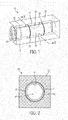
FIG. 1 is a perspective view of a level vial according to an embodiment of the invention; -
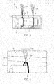
FIG. 2 is a cross-sectional view of the level vial shown inFIG. 1 as seen from and in the direction indicated by line 2-2; -
FIG. 3 is a perspective view of the inner structure of the level vial shown inFIG. 1 ; -
FIG. 4 is a perspective view of the level vial shown inFIG. 1 after the outer structure is formed over the inner structure; -
FIG. 5 is a perspective view of the level vial shown inFIG. 1 where a marking is being formed with a laser beam; -
FIG. 6 shows a close-up view of a portion of the level vial shown inFIG. 1 where a marking is being formed with a laser beam; -
FIG. 7A is a perspective view of a level vial according to an embodiment of the invention wherein the outer structure of the level vial has a disc shape; -
FIG. 7B is a perspective view of a level vial according to an embodiment of the invention wherein the outer structure of the level vial has a generally cylindrical upper portion and a rectangular box lower portion; and -
FIG. 7C is a perspective view of a level vial according to an embodiment of the invention wherein the outer structure of the level vial has four perpendicular planar sides in a rectangular box configuration peripherally surrounding the inner structure, and two convex sides, each on respective opposite ends of the inner structure; -
FIG. 8 is a cross-sectional view of a level vial according to an embodiment of the invention; -
FIG. 9 is a cross-sectional view of the level vial shown inFIG. 8 as seen from and in the direction indicated by line 9-9; and -
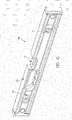
FIG 10 is a perspective view of a level vial according to an embodiment of the invention mounted to a level frame. - Referring now more particularly to the drawings,
FIGS. 1-6 show an embodiment of a level vial, generally indicated at 10, embodying various principles of the present specification. Turning toFIG. 1 ,level vial 10 includes a firstinner structure 11 surrounded by a secondouter structure 12.Inner structure 11 andouter structure 12 are made from a transparent or a translucent material.Inner structure 11 includes anouter surface 15 and aninterior surface 17. Aninternal cavity 16 is defined byinterior surface 17. In one embodiment, theouter surface 15 of tubularinner structure 11 has a generally cylindrical shape. In other embodiments, theinner structure 11 is not tubular but rather may be other shapes, such as a general disc shape. A disc shaped inner structure may be used, for example, in a bulls-eye level.Markings 13 are formed on theinner structure 11. In one embodiment, themarkings 13 are formed on theouter surface 15. In another embodiment,markings 13 are formed below theouter surface 15. In one embodiment,markings 13 are formed by a laser beam according to a method as described below.Markings 13 are spaced apart to dividelevel vial 10 in three generally equal portions. In other embodiments,markings 13 need not dividelevel vial 10 into equal portions. In yet other embodiments, only one marking positioned at the center oflevel vial 10 is used. In one embodiment, theinternal cavity 16, i.e. theinterior surface 17, ofinner structure 11 is barrel shaped. In other embodiments, theinterior surface 17 may be banana shaped, or curved cylinder shaped, with the bulged portion disposed upwardly. -
Interior cavity 16 ofinner structure 11 may be filled with enough liquid to leave an air bubble asindicia 19 for making level measurements. In one embodiment,indicia 19 may be formed by adding a second liquid with a lower density into a first liquid, in which case, color may be added to either liquid to provide contrast. -
Inner structure 11 may be formed by various methods. In one embodiment,inner structure 11 is injection molded around a core pin. Injection moldinginner structure 11 may result in one end being sealed and the opposite end having an open side. The open end ofinner structure 11 may be sized to be larger than the rest ofinner structure 11 to accommodatecap 14.Interior surface 17 ofinner structure 11 may include aledge 18 to supportcap 14 whencap 14 is inserted into the open end ofinner structure 11.Cap 14 may be secured onto the open end ofinner structure 11 after the molding process, and after liquid has been placed in theinternal cavity 16 in order to seal the liquid in theinner structure 11. In other embodiments, injection molding forms two open ends, and acap 14 is secured to both open ends ofinner structure 11 after formation ofinner structure 11.Cap 14 may be secured through ultrasonic welding. Other methods may be used to forminner structure 11, including extrusion forming, machining, and milling. -
Inner structure 11 may be formed using a clear plastic such as polycarbonate. A polycarbonate having any of or combinations of the following physical properties may be used: a density of about 1.20 g/cm3, a melt index (300°C/1.2 kg) of about 22 g/10 minutes, a molding shrinkage - flow of about 0.50 to 0.70%, a water absorption (23°C, 24 hr) of about 0.15%, and a water absorption (equilibrium, 23°C, 50% RH) of about 0.32%. A polycarbonate having any of or combinations of the following mechanical properties may be used: a tensile modulus of about 2340 MPA, a tensile strength to yield of about 60.0 MPA, a tensile strength to break of about 65.5 MPA, a tensile elongation to yield of about 6.0%, a tensile elongation to break of about 120%, a flexural modulus of about 2410 MPA, a flexural strength of about 96.5 MPA, and a taber abrasion resistance of about 45%. A polycarbonate having any of or combinations of the following impact properties may be used: a Charpy notched impact strength (23°C) of about 20 kJ/m2, a Notched Izod impact (23°C) of about 747 J/m, an instrumented dart impact (23°C, total energy) of about 72.3 J, and a tensile impact strength of about 378 kJ/m2. A polycarbonate having a Rockwell hardness of about 118 (R-Scale) or about 73 (M-Scale) may be used. A polycarbonate having any of or combinations of the following thermal properties may be used: a deflection temperature under load of about 142°C (0.45 MPa, annealed), about 126°C (1.8 MPa, unannealed), or about 139°C (1.8 MPa, annealed), a Vicat softening temperature of about 147°C, a ball indentation temperature of about 125°C, and a CLTE - flow (-40 to 82°C) or about 0.000068 cm/cm/°C. A polycarbonate having any of or combinations of the following electrical properties may be used: a volume resistivity of about 2.0E+17 ohm-cm, a dielectric strength of about 17 kV/mm, a dielectric constant (60 Hz) of about 3.00, a dielectric constant (1E+6 Hz) of about 3.00, a dissipation factor (50 Hz) of about 0.0010, a dissipation factor (1 E+6 Hz) of about 0.0020, and a comparative tracking index (2.00mm, Solution A) of about 250 V. A polycarbonate having any of or combinations of the following flammability properties may be used: a UL flame rating of V-2 at 1.59 mm, a UL flame rating of V-2 at 3.18 mm, an oxygen index of about 26%, and an average extent of burning of about 3 cm. A polycarbonate having any of or combinations of the following optical properties may be used: a refractive index of about 1.586, a transmittance of about 89.0%, and a haze of about 1.0%. In one embodiment,inner structure 11 is formed using the CALIBRE™ 303EP-22 polycarbonate resin from The Dow Chemical Company. A laser sensitive additive may optionally be added to the material of theinner structure 11. -
Outer structure 12 is formed over theouter surface 15 ofinner structure 11. In one embodiment,outer structure 12 is injection molded aroundinner structure 11. As shown in the figure, in one embodiment theouter structure 12 may form a rectangular block surroundinginner structure 11. In other embodiments,outer structure 12 may be formed to have any desired shape including a cylinder, disc, square block, rectangular block, half cylinder, a shape having a generally cylindrical upper portion and a rectangular block lower portion, and a shape having four perpendicular planar sides in a rectangular box configuration peripherally surrounding the inner structure and two convex sides, each on respective opposite ends of the inner structure. - In one embodiment,
outer structure 12 is formed from an acrylic such as poly(methyl methacrylate) (PMMA). A PMMA having any of or combinations of the following mechanical properties may be used: a tensile modulus of about 3300 MPA, a stress at break of about 77 MPA, a strain at break of about 5.5%, and a Charpy impact strength (23°C) of about 20 kJ/m2. A PMMA having any of or combinations of the following thermal properties may be used: a Vicat softening temperature of about 108°C, a glass transition temperature of about 117 °C, a temperature of deflection under 0.45 MPa load of about 103°C, a temperature of deflection under 1.8 MPa load of about 98°C, a coefficient of linear thermal expansion of about 8, a fire rating of B2, and a flammability UL 94 of HB. A PMMA with a melt volume rate of about 3 cm3/10 min may be used. A PMMA having any of or combinations of the following optical properties may be used: a luminous transmittance of about 92%, a haze of less than 0.5, and a refractive index of about 1.49. A PMMA having a density of about 1.19 g/cm3 may be used. In one embodiment,outer structure 12 is formed using the PLEXIGLAS® 8N molding compound from Evonik Industries. -
Inner structure 11 andouter structure 12 may be formed to any size depending on the need. For example,level vial 10 may be used alone, attached to a product, or in conjunction with a level frame. If used in conjunction with a level frame (as shown inFIG. 10 ),level vial 10 may be sized to fit into the level frame. If used alone,level vial 10 may be formed to a larger size to allow for ease of handling by a user. - Referring to
FIG. 2 , a cross-sectional view of thelevel vial 10 inFIG. 1 is shown as seen from and in the direction indicated by line 2-2 inFIG. 1 .Inner structure 11 has a thickness that is defined byouter surface 15 andinterior surface 17.Inner structure 11 may be formed to have any thickness desired. Aninner structure 11 that is thick may be stronger. Aninner structure 11 that is thin may use less material. -
Internal cavity 16 is defined by theinterior surface 17 ofinner structure 11. In the embodiment shown in the figure,inner cavity 16 has a substantially circular cross section. For aninternal cavity 16 that is barrel shaped, the cross sectional diameter ofinternal cavity 16 varies along the length oflevel vial 10. For an embodiment where theinternal cavity 16 is barrel shaped and theouter surface 15 is cylindrical, the thickness ofinner structure 11 varies along the length oflevel vial 10. - In one embodiment,
inner structure 11 includes marking 13 formed between theouter surface 15 andinterior surface 17, such as immediately beneath theouter surface 15. In one embodiment, marking 13 may be formed on theouter surface 15 ofinner structure 11. Providing marking 13 either on theouter surface 15 ofinner structure 11 or between theouter surface 15 andinterior surface 17 allowsinterior surface 17 ofinner structure 11 to remain a smooth continuous surface with no interruptions or discontinuities. Marking 13 may be formed using a laser beam according to a method as described below. -
Outer structure 12 surrounds theouter surface 15 ofinner structure 11. In the embodiment shown inFIG. 2 ,outer structure 12 forms a square cross sectional shape. In other embodiments,outer structure 12 may be formed to have different cross sectional shapes, such as rectangles and circles.Outer structure 12 may be formed to any size depending on the need and desire. - Turning to
FIGS. 3-5 , progression ofmanufacturing level vial 10 according to one embodiment is shown. As shown inFIG. 3 ,inner structure 11 is first made.Inner structure 11 may be produced by injection molding around a core pin, extrusion forming, machining, or milling.Inner structure 11 includes anouter surface 15 and aninterior surface 17. Aninternal cavity 16 is defined byinterior surface 17. An opening is left in one end ofinner structure 11 in order to fillcavity 16 with the liquid.Interior surface 17 ofinner structure 11 may include aledge 18 to supportcap 14 whencap 14 is inserted into the open end ofinner structure 11. The opening may be sealed with acap 14. - As shown in
FIG. 4 ,outer structure 12 is formed around theouter surface 15 ofinner structure 11. In one embodiment,outer structure 12 is injection molded around theouter surface 15 ofinner structure 11. In the embodiment shown inFIG. 4 ,outer structure 12 forms a rectangular block aroundinner structure 11 with an opening for acap 14. In other embodiments,outer structure 12 may be formed to have other shapes, including a cylinder, disc, square block, half cylinder, a shape having a generally cylindrical upper portion and a rectangular block lower portion, and a shape having four perpendicular planar sides in a rectangular box configuration peripherally surrounding the inner structure and two convex sides, each on respective opposite ends of the inner structure. In other embodiments,outer structure 12 may be formed to any size depending on need and desire. In one embodiment,outer structure 12 surrounds only a periphery ofinner structure 12. -
Interior cavity 16 ofinner structure 11 may be filled with enough liquid to leave an air bubble as indicia for making level measurements. In one embodiment, indicia may be formed by adding a second liquid with a lower density into a first liquid, in which case, color may be added to either liquid to provide contrast. After fillinginterior cavity 16 ofinner structure 11,cap 14 is secured ontoinner structure 11 to seal in the liquid.Cap 14 may be secured by ultrasonic welding. The filling ofinterior cavity 16 with a liquid and sealing withcap 14 may be performed at various stages of the manufacturing process. In one embodiment,interior cavity 16 is filled with liquid and sealed after formation ofinner structure 11 as shown inFIG. 3 . In one embodiment,interior cavity 16 is filled with liquid and sealed after formation ofinner structure 11 and after formation ofouter structure 15 as shown inFIG. 4 . In one embodiment,interior cavity 16 is filled with liquid and sealed after formation ofinner structure 11, after formation ofouter structure 15, and after formation of marking 13 as shown inFIG. 5 and described below. - Turning to
FIG. 5 ,markings 13 are formed oninner structure 11. In one embodiment, the markings are formed betweenouter surface 15 andinterior surface 17. In one embodiment,markings 13 are formed on theouter surface 15 ofinner structure 11. In one embodiment, themarkings 13 are formed on theouter surface 15 and also between theouter surface 15 andinner surface 17.Markings 13 are formed bylaser beam 25. In one embodiment,laser beam 25 is transmitted throughouter structure 12 and focused onto theouter surface 15 ofinner structure 11 or intoinner structure 11.Focal point 26 oflaser beam 25 burns, carbonizes, foams, etches, ablates, forms bubbles on, or otherwise marksinner structure 11. In one embodiment, thelaser beam 25 can be directed or guided by one or more optics (or optical elements), such as one or more lenses, mirrors, or combinations thereof, onto the area to be marked. The optics (e.g., lenses and/or mirrors) can also be configured and positioned relative to the inner structure 11 (while thevial 10 is being supported by an appropriate support structure) such that thefocal point 26 of the laser radiation will be positioned at the area on theinner structure 11 to be marked. In one embodiment, only thefocal point 26 oflaser beam 25 leaves a mark. In this embodiment, the portions oflaser beam 25 prior to and afterfocal point 26 do not leave a mark inouter structure 12 orinner structure 11. In one embodiment,laser beam 25 forms microscopic or nano-sized bubbles beneath and/or on theouter surface 15 which appears to the naked eye as a dark (e.g. black) mark.Level vial 10 may be rotated along the barrel axis in a 360° manner so that marking 13 forms an annular structure around the periphery ofinner structure 11. In one embodiment, such as for a bulls-eye vial, marking 13 may form an annular structure on one side of the vial as a reference. In one embodiment,laser beam 25 is rotated aroundlevel vial 10 to form marking 13. In other embodiments, two or more laser beams may be used to form two or more markings simultaneously. - Turning to
FIG. 6 , a close-up view of the formation of marking 13 withlaser beam 25 according to an embodiment is shown.Level vial 10 includes aninner structure 11 and anouter structure 12.Laser beam 25 is transmitted throughouter structure 12 and ontoinner structure 11.Focal point 26 oflaser beam 25 burns, carbonizes, foams, etches, ablates, or otherwise marks the outer surface of inner structure 21. The materials of theinner structure 11 andouter structure 12 are selected in conjunction with the characteristics (e.g., power, wavelength, duration) of the laser beam such thatinner structure 11 is marked whilelaser beam 25 penetrates the material of theouter structure 12 so as to not leave a mark in theouter structure 12. - In one embodiment, a fiber laser marking system may be used to form marking 13 on or in
inner structure 11. The fiber laser may, for example, be a 20 watt laser set at a 55% power level with a speed of 1500 mm/s, a frequency of 80 kHz, and a trigger time of 6 µs. In other embodiments, YAG or vanadate lasers may be used. - Referring to
FIGS. 7A-7C , different embodiments of a level vial are shown, each with a different shape formed by the outer structure.FIG. 7A showslevel vial 70a, which includesinner structure 11 andouter structure 12.Inner structure 11 is tubular and includesmarkings 13.Outer structure 12 oflevel vial 70a forms a disc shape.FIG. 7B showslevel vial 70b, which includesinner structure 11 andouter structure 12.Inner structure 12 is tubular and includesmarkings 13.Outer structure 12 oflevel vial 70b has a generally cylindrical upper portion and a rectangular box lower portion.FIG. 7C showslevel vial 70c.Level vial 70c includesinner structure 11 andouter structure 12.Inner structure 11 is tubular and includesmarkings 13.Outer structure 12 oflevel vial 70c has four perpendicular planar sides in a rectangular box configuration peripherally surrounding theinner structure 11 and two convex sides, each on respective opposite ends of theinner structure 11. In other embodiments, the outer structure of a level vial may form any shape desired including cylinder, square block, and rectangular block. - Referring now to
FIGS. 8 and 9 , views of alevel vial 80 according to another embodiment are shown. Theouter structure 12 oflevel vial 80 has an overall geometry of a disc.Level vial 80 includescavities 86 in theouter structure 12.Cavities 86 may be utilized to lessen the amount of material used or aid in the formation of the outer structure.FIG. 8 shows a cross-sectional view oflevel vial 80. This view is taken though the center of disc shapedlevel vial 80 with one of the flat sides oflevel vial 80 being disposed downwardly.Level vial 80 includesouter structure 12 surroundinginner structure 11.Interior cavity 16 is defined by the interior surface ofinner structure 11.Interior cavity 16 has a barrel-shape.Interior cavity 16 may be filled with enough liquid to leave an air bubble asindicia 19 for making level measurements. In one embodiment,indicia 19 may be formed by adding a second liquid with a lower density into a first liquid, in which case, color may be added to either liquid to provide contrast.Cap 14 is inserted into the open end ofinner structure 11, resting on theledge 18 formed by the interior surface ofinner structure 11.Cap 14 is secured onto the open end ofinner structure 11 to seal in a liquid ininterior cavity 16.Cap 14 may be secured by ultrasonic welding. The dotted lines represent one location where markings may be formed onlevel vial 80 according to the laser marking methods described above. - Referring to
FIG. 9 , a cross-sectional view of thelevel vial 80 is shown as seen from and in the direction indicated by line 9-9 inFIG. 8 . The cross-sectional view shown inFIG. 9 is taken through the middle oflevel vial 80.Level vial 80 includesouter structure 12 surroundinginner structure 11.Inner structure 11 includes an interior surface that definesinterior cavity 16.Cavities 86 are formed inouter structure 12. In one embodiment,cavities 86 may be formed as part of the formation ofouter structure 12. In one embodiment,cavities 86 may be formed inouter structure 12 after the formation ofouter structure 12, such as by milling or machining outer structure after formation. - Referring to
FIG. 10 , alevel assembly 100 is shown.Level vial 10 is placed inlevel frame 20. As shown in the figure, onelevel vial 10 is placed in a horizontal orientation on thelevel frame 20, while twolevel vials 10 are placed in a vertical orientation.Level vial 10 may be placed in other orientations onlevel frame 20 such as in a diagonal orientation. - Although the present patent application has been described in detail for the purpose of illustration, it is to be understood that such detail is solely for that purpose and that the present patent application is not limited to the disclosed embodiments, but, on the contrary, is intended to cover modifications and equivalent arrangements that are within the spirit and scope of the appended claims. In addition, it is to be understood that the present patent application contemplates that, to the extent possible, one or more features of any embodiment can be combined with one or more features of any other embodiment.
Claims (15)
- A method for manufacturing a level vial comprising:providing a first inner structure having an outer surface and an interior surface, wherein the interior surface defines an internal cavity;molding a second structure over the outer surface of the first inner structure;transmitting radiation through the second structure to form a marking on the first inner structure;providing a liquid into the internal cavity; andsealing the liquid in the internal cavity.
- The method of claim 1, wherein the radiation is provided by a laser, and wherein the marking comprises bubbles formed on and/or beneath the outer surface of the first inner structure.
- The method of claims 1 or 2, wherein the internal cavity is barrel-shaped and formed by internal machining or milling of the interior surface of the first inner structure.
- The method of any of claims 1 to 3, wherein the second structure is molded over the outer surface of the first inner structure by injection molding.
- The method of any of the preceding claims, wherein the marking is a ring around the first inner structure or two spaced markings around the first inner structure.
- The method of claim 1, wherein the radiation does not form a marking on the second structure.
- A level vial comprising:a first inner structure having an outer surface and an interior surface, wherein the interior surface defines an internal cavity;a second structure disposed over the outer surface of the first inner structure;a marking between the outer surface and interior surface of the first inner structure and/or on the outer surface of the first inner structure, wherein the marking is a laser marking; anda liquid sealed within the internal cavity.
- The level vial of claim 7, wherein the laser marking is a burn, an etching, an ablation, a carbonization, or a foaming.
- The level vial of claims 7 or 8, wherein the internal cavity is barrel-shaped.
- The level vial of claims 7 to 9, wherein the marking comprises a ring around the first inner structure.
- The level vial of claims 7 to 10, wherein the marking comprises a pair of spaced rings around the first inner structure.
- The level vial of claims 7 to 11, wherein an outer surface of the second structure comprises a shape selected from the group consisting of a cylinder, disc, square block, rectangular block, half cylinder, a shape having a generally cylindrical upper portion and a rectangular box lower, and a shape having four perpendicular planar sides in a rectangular box configuration peripherally surrounding the inner structure and two convex sides on respective opposite ends of the inner structure.
- The level vial of claims 7 to 12, wherein the first inner structure is tubular.
- The level vial of claims 7 to 13, wherein the first inner structure is a curved cylinder shape.
- The level vial of claims 7 to 14, wherein the marking comprises bubbles formed in the material of the first inner structure.
Applications Claiming Priority (1)
| Application Number | Priority Date | Filing Date | Title |
|---|---|---|---|
| US14/107,908 US9170104B2 (en) | 2013-12-16 | 2013-12-16 | Level vial and method of manufacturing same |
Publications (2)
| Publication Number | Publication Date |
|---|---|
| EP2896932A1 true EP2896932A1 (en) | 2015-07-22 |
| EP2896932B1 EP2896932B1 (en) | 2016-11-23 |
Family
ID=52449913
Family Applications (1)
| Application Number | Title | Priority Date | Filing Date |
|---|---|---|---|
| EP14198128.2A Active EP2896932B1 (en) | 2013-12-16 | 2014-12-16 | Level vial and method of manufacturing same |
Country Status (3)
| Country | Link |
|---|---|
| US (1) | US9170104B2 (en) |
| EP (1) | EP2896932B1 (en) |
| CA (1) | CA2872282C (en) |
Families Citing this family (2)
| Publication number | Priority date | Publication date | Assignee | Title |
|---|---|---|---|---|
| US9625260B2 (en) | 2014-04-16 | 2017-04-18 | Stanley Black & Decker, Inc. | Carbon fiber composite level and method of manufacturing same |
| US10001371B2 (en) * | 2014-11-13 | 2018-06-19 | Milwaukee Electric Tool Corporation | Level |
Citations (5)
| Publication number | Priority date | Publication date | Assignee | Title |
|---|---|---|---|---|
| EP0704673A1 (en) * | 1994-08-01 | 1996-04-03 | Bayerische Mass-Industrie Arno Keller Gmbh | Manufacturing method for spirit level with adjustable vial |
| DE29800798U1 (en) * | 1998-01-21 | 1998-08-06 | Bayerische Maßindustrie Arno Keller GmbH, 91217 Hersbruck | Transparent liquid container for spirit levels |
| EP0932024B1 (en) | 1998-01-21 | 2001-08-08 | Bayerische Mass-Industrie Arno Keller Gmbh | Method and device for the marking of a plastic container for liquid |
| US20050229412A1 (en) * | 2004-04-16 | 2005-10-20 | Foran Thomas P | Overmolded vial for use with a level |
| GB2474952A (en) * | 2009-10-27 | 2011-05-04 | Michael S Steele | Hand tool used to level a surface or electrical device |
Family Cites Families (25)
| Publication number | Priority date | Publication date | Assignee | Title |
|---|---|---|---|---|
| US3311990A (en) | 1967-04-04 | Edward j. brenner | ||
| GB1037566A (en) | 1964-07-14 | 1966-07-27 | Perfection Metalwares Ltd | Improvements relating to spirit levels |
| US3593428A (en) | 1968-09-26 | 1971-07-20 | Great Neck Saw Manufacturers | Spirit level |
| US3842514A (en) | 1968-09-28 | 1974-10-22 | G Scheyer | Liquid level |
| FR2471581A1 (en) | 1979-12-13 | 1981-06-19 | Stanley Mabo | IMPROVED PROCESS FOR THE MANUFACTURE OF A BUBBLE LEVEL FLASK |
| IL63934A (en) | 1981-09-25 | 1985-01-31 | Drori Michael | Method of manufacturing level vials |
| DE4014638A1 (en) | 1990-05-08 | 1991-11-14 | Bayerische Massindustrie Arno | DRAGONFLY FOR LEVELS |
| US5588217A (en) | 1995-03-01 | 1996-12-31 | Empire Level Mfg. Co. | Level vial assembly with encapsulated vial |
| US5651186A (en) | 1995-08-09 | 1997-07-29 | Empire Level Mfg. Corp. | Liquid level vial and method for making the vial |
| DE19822646C1 (en) | 1998-01-21 | 1999-05-06 | Bayerische Mas Ind Arno Keller | Marking transparent plastic container for fluids, especially spirit level capsule |
| DE69905557T2 (en) | 1998-03-31 | 2003-08-28 | Johnson Level & Tool Mfg. Co., Inc. | CASTING PROCESS WITH INSERTIBLE DRAGONFLY, EXAMPLE FOR A SPIRIT LEVEL, AND MOLDED OBJECT |
| US6343422B1 (en) * | 1999-05-31 | 2002-02-05 | Kabushiki Kaisha Topcon | Tilt angel measuring device |
| US6735880B1 (en) | 1999-11-22 | 2004-05-18 | Great Neck Saw Manufacturers, Inc. | Vial and method of making same |
| JP2004532756A (en) | 2001-06-18 | 2004-10-28 | ベクトン・ディキンソン・アンド・カンパニー | Multilayer container and method for forming multilayer container |
| DE202004000780U1 (en) | 2004-01-19 | 2004-05-13 | Sola-Messwerkzeuge Gmbh | Dragonfly for a spirit level |
| US6957494B1 (en) | 2004-04-16 | 2005-10-25 | Empire Level Mfg. Corp. | Dark-banded vial for use with level |
| US7350305B2 (en) * | 2006-02-21 | 2008-04-01 | Molitech Corporation | Laser activated audible signal emitting leveler |
| US7464479B2 (en) | 2006-05-18 | 2008-12-16 | The Stanley Works | Level vial and manufacturing method therefor |
| WO2008124751A1 (en) * | 2007-04-10 | 2008-10-16 | Allemand James S | Level tool |
| EP2051043A1 (en) | 2007-10-17 | 2009-04-22 | SOLA-Messwerkzeuge GmbH | Airlessly sealed vial |
| IL195885A0 (en) * | 2008-12-11 | 2009-09-01 | Kapro Ind Ltd | Spirit level with color contrasted bubble vial |
| US9464895B2 (en) * | 2009-03-13 | 2016-10-11 | Otl Dynamics Llc | Remote leveling and positioning system and method |
| US8910390B2 (en) | 2010-10-26 | 2014-12-16 | Milwaukee Electric Tool Corporation | Level |
| US9546867B2 (en) * | 2010-12-31 | 2017-01-17 | The Regular Guys, Llc | Multi-function level with a joinable end |
| US20150113819A1 (en) * | 2013-10-28 | 2015-04-30 | Mark L. Silberberg | Five Vial Level |
-
2013
- 2013-12-16 US US14/107,908 patent/US9170104B2/en active Active
-
2014
- 2014-11-25 CA CA2872282A patent/CA2872282C/en not_active Expired - Fee Related
- 2014-12-16 EP EP14198128.2A patent/EP2896932B1/en active Active
Patent Citations (5)
| Publication number | Priority date | Publication date | Assignee | Title |
|---|---|---|---|---|
| EP0704673A1 (en) * | 1994-08-01 | 1996-04-03 | Bayerische Mass-Industrie Arno Keller Gmbh | Manufacturing method for spirit level with adjustable vial |
| DE29800798U1 (en) * | 1998-01-21 | 1998-08-06 | Bayerische Maßindustrie Arno Keller GmbH, 91217 Hersbruck | Transparent liquid container for spirit levels |
| EP0932024B1 (en) | 1998-01-21 | 2001-08-08 | Bayerische Mass-Industrie Arno Keller Gmbh | Method and device for the marking of a plastic container for liquid |
| US20050229412A1 (en) * | 2004-04-16 | 2005-10-20 | Foran Thomas P | Overmolded vial for use with a level |
| GB2474952A (en) * | 2009-10-27 | 2011-05-04 | Michael S Steele | Hand tool used to level a surface or electrical device |
Also Published As
| Publication number | Publication date |
|---|---|
| CA2872282A1 (en) | 2015-06-16 |
| CA2872282C (en) | 2018-12-11 |
| EP2896932B1 (en) | 2016-11-23 |
| US9170104B2 (en) | 2015-10-27 |
| US20150168143A1 (en) | 2015-06-18 |
Similar Documents
| Publication | Publication Date | Title |
|---|---|---|
| US8053079B2 (en) | Sheet glass laminate structure and mulitiple glass laminate structure | |
| EP2896932B1 (en) | Level vial and method of manufacturing same | |
| US3573150A (en) | Transparent armor | |
| EP1736802A2 (en) | Variable-focus lens and method of manufacturing the same | |
| KR20160106003A (en) | Tempered glass plate and portable terminal using same | |
| WO2000030836A2 (en) | Method for side-fill lens casting | |
| KR101225596B1 (en) | Variable-focus lens | |
| KR102150292B1 (en) | Soft linear illuminant, and manufacturing method thereof | |
| JPWO2011155550A1 (en) | Aromatic polycarbonate polarizing lens | |
| WO2013012044A1 (en) | Laminated glass and translucent soundproof panel | |
| CN104924881A (en) | Engagement structure of door equipped on vehicle | |
| KR20170018325A (en) | Glass article and method for producing same | |
| ATE488542T1 (en) | POLYCARBONATES WITH FLUORALKYLENE CARBONATE END GROUPS | |
| US6893126B2 (en) | Optical sheet for use in manufacturing a cylindrically shaped optically correct visor and method of manufacturing said visor | |
| JP2009001478A (en) | Laminated glass and its manufacturing method | |
| EP1686412A3 (en) | Optical component and method of manufacture of optical component | |
| CN101666465A (en) | Cylindrical light guide and illuminating device | |
| JP2014099302A (en) | Resin lighting cover | |
| CN105842860A (en) | 3D (three dimensional) lenticular film with alignment targets, optical film and display device | |
| WO2006098137A1 (en) | Light guiding plate formed of transparent resin, planar light source, and light guiding plate manufacturing method | |
| CN109375303A (en) | A kind of external fit type reflective membrane and preparation method thereof | |
| KR20230096559A (en) | Method for manufacturing pouch case for secondary battery | |
| JP6511941B2 (en) | Resin optical molded body and method for manufacturing the same | |
| CN208156224U (en) | A kind of cancave cambered surface reflecting element for parallel light path modification | |
| JP2011107405A (en) | Viewing angle control sheet and method of manufacturing the same |
Legal Events
| Date | Code | Title | Description |
|---|---|---|---|
| PUAI | Public reference made under article 153(3) epc to a published international application that has entered the european phase |
Free format text: ORIGINAL CODE: 0009012 |
|
| 17P | Request for examination filed |
Effective date: 20141216 |
|
| AK | Designated contracting states |
Kind code of ref document: A1 Designated state(s): AL AT BE BG CH CY CZ DE DK EE ES FI FR GB GR HR HU IE IS IT LI LT LU LV MC MK MT NL NO PL PT RO RS SE SI SK SM TR |
|
| AX | Request for extension of the european patent |
Extension state: BA ME |
|
| 17P | Request for examination filed |
Effective date: 20160121 |
|
| RBV | Designated contracting states (corrected) |
Designated state(s): AL AT BE BG CH CY CZ DE DK EE ES FI FR GB GR HR HU IE IS IT LI LT LU LV MC MK MT NL NO PL PT RO RS SE SI SK SM TR |
|
| GRAP | Despatch of communication of intention to grant a patent |
Free format text: ORIGINAL CODE: EPIDOSNIGR1 |
|
| RIC1 | Information provided on ipc code assigned before grant |
Ipc: G01C 9/34 20060101ALI20160801BHEP Ipc: G01C 9/32 20060101AFI20160801BHEP |
|
| INTG | Intention to grant announced |
Effective date: 20160830 |
|
| GRAS | Grant fee paid |
Free format text: ORIGINAL CODE: EPIDOSNIGR3 |
|
| GRAA | (expected) grant |
Free format text: ORIGINAL CODE: 0009210 |
|
| AK | Designated contracting states |
Kind code of ref document: B1 Designated state(s): AL AT BE BG CH CY CZ DE DK EE ES FI FR GB GR HR HU IE IS IT LI LT LU LV MC MK MT NL NO PL PT RO RS SE SI SK SM TR |
|
| REG | Reference to a national code |
Ref country code: GB Ref legal event code: FG4D |
|
| REG | Reference to a national code |
Ref country code: FR Ref legal event code: PLFP Year of fee payment: 3 |
|
| REG | Reference to a national code |
Ref country code: CH Ref legal event code: EP |
|
| REG | Reference to a national code |
Ref country code: IE Ref legal event code: FG4D |
|
| REG | Reference to a national code |
Ref country code: AT Ref legal event code: REF Ref document number: 848321 Country of ref document: AT Kind code of ref document: T Effective date: 20161215 |
|
| REG | Reference to a national code |
Ref country code: DE Ref legal event code: R096 Ref document number: 602014005024 Country of ref document: DE |
|
| PG25 | Lapsed in a contracting state [announced via postgrant information from national office to epo] |
Ref country code: LV Free format text: LAPSE BECAUSE OF FAILURE TO SUBMIT A TRANSLATION OF THE DESCRIPTION OR TO PAY THE FEE WITHIN THE PRESCRIBED TIME-LIMIT Effective date: 20161123 |
|
| REG | Reference to a national code |
Ref country code: LT Ref legal event code: MG4D |
|
| REG | Reference to a national code |
Ref country code: NL Ref legal event code: MP Effective date: 20161123 |
|
| REG | Reference to a national code |
Ref country code: AT Ref legal event code: MK05 Ref document number: 848321 Country of ref document: AT Kind code of ref document: T Effective date: 20161123 |
|
| PG25 | Lapsed in a contracting state [announced via postgrant information from national office to epo] |
Ref country code: NL Free format text: LAPSE BECAUSE OF FAILURE TO SUBMIT A TRANSLATION OF THE DESCRIPTION OR TO PAY THE FEE WITHIN THE PRESCRIBED TIME-LIMIT Effective date: 20161123 Ref country code: LT Free format text: LAPSE BECAUSE OF FAILURE TO SUBMIT A TRANSLATION OF THE DESCRIPTION OR TO PAY THE FEE WITHIN THE PRESCRIBED TIME-LIMIT Effective date: 20161123 Ref country code: NO Free format text: LAPSE BECAUSE OF FAILURE TO SUBMIT A TRANSLATION OF THE DESCRIPTION OR TO PAY THE FEE WITHIN THE PRESCRIBED TIME-LIMIT Effective date: 20170223 Ref country code: GR Free format text: LAPSE BECAUSE OF FAILURE TO SUBMIT A TRANSLATION OF THE DESCRIPTION OR TO PAY THE FEE WITHIN THE PRESCRIBED TIME-LIMIT Effective date: 20170224 Ref country code: SE Free format text: LAPSE BECAUSE OF FAILURE TO SUBMIT A TRANSLATION OF THE DESCRIPTION OR TO PAY THE FEE WITHIN THE PRESCRIBED TIME-LIMIT Effective date: 20161123 |
|
| PG25 | Lapsed in a contracting state [announced via postgrant information from national office to epo] |
Ref country code: BE Free format text: LAPSE BECAUSE OF NON-PAYMENT OF DUE FEES Effective date: 20161231 Ref country code: PT Free format text: LAPSE BECAUSE OF FAILURE TO SUBMIT A TRANSLATION OF THE DESCRIPTION OR TO PAY THE FEE WITHIN THE PRESCRIBED TIME-LIMIT Effective date: 20170323 Ref country code: HR Free format text: LAPSE BECAUSE OF FAILURE TO SUBMIT A TRANSLATION OF THE DESCRIPTION OR TO PAY THE FEE WITHIN THE PRESCRIBED TIME-LIMIT Effective date: 20161123 Ref country code: ES Free format text: LAPSE BECAUSE OF FAILURE TO SUBMIT A TRANSLATION OF THE DESCRIPTION OR TO PAY THE FEE WITHIN THE PRESCRIBED TIME-LIMIT Effective date: 20161123 Ref country code: AT Free format text: LAPSE BECAUSE OF FAILURE TO SUBMIT A TRANSLATION OF THE DESCRIPTION OR TO PAY THE FEE WITHIN THE PRESCRIBED TIME-LIMIT Effective date: 20161123 Ref country code: RS Free format text: LAPSE BECAUSE OF FAILURE TO SUBMIT A TRANSLATION OF THE DESCRIPTION OR TO PAY THE FEE WITHIN THE PRESCRIBED TIME-LIMIT Effective date: 20161123 Ref country code: FI Free format text: LAPSE BECAUSE OF FAILURE TO SUBMIT A TRANSLATION OF THE DESCRIPTION OR TO PAY THE FEE WITHIN THE PRESCRIBED TIME-LIMIT Effective date: 20161123 Ref country code: PL Free format text: LAPSE BECAUSE OF FAILURE TO SUBMIT A TRANSLATION OF THE DESCRIPTION OR TO PAY THE FEE WITHIN THE PRESCRIBED TIME-LIMIT Effective date: 20161123 |
|
| PG25 | Lapsed in a contracting state [announced via postgrant information from national office to epo] |
Ref country code: RO Free format text: LAPSE BECAUSE OF FAILURE TO SUBMIT A TRANSLATION OF THE DESCRIPTION OR TO PAY THE FEE WITHIN THE PRESCRIBED TIME-LIMIT Effective date: 20161123 Ref country code: DK Free format text: LAPSE BECAUSE OF FAILURE TO SUBMIT A TRANSLATION OF THE DESCRIPTION OR TO PAY THE FEE WITHIN THE PRESCRIBED TIME-LIMIT Effective date: 20161123 Ref country code: EE Free format text: LAPSE BECAUSE OF FAILURE TO SUBMIT A TRANSLATION OF THE DESCRIPTION OR TO PAY THE FEE WITHIN THE PRESCRIBED TIME-LIMIT Effective date: 20161123 Ref country code: CZ Free format text: LAPSE BECAUSE OF FAILURE TO SUBMIT A TRANSLATION OF THE DESCRIPTION OR TO PAY THE FEE WITHIN THE PRESCRIBED TIME-LIMIT Effective date: 20161123 Ref country code: SK Free format text: LAPSE BECAUSE OF FAILURE TO SUBMIT A TRANSLATION OF THE DESCRIPTION OR TO PAY THE FEE WITHIN THE PRESCRIBED TIME-LIMIT Effective date: 20161123 |
|
| REG | Reference to a national code |
Ref country code: DE Ref legal event code: R097 Ref document number: 602014005024 Country of ref document: DE |
|
| PG25 | Lapsed in a contracting state [announced via postgrant information from national office to epo] |
Ref country code: IT Free format text: LAPSE BECAUSE OF FAILURE TO SUBMIT A TRANSLATION OF THE DESCRIPTION OR TO PAY THE FEE WITHIN THE PRESCRIBED TIME-LIMIT Effective date: 20161123 Ref country code: SM Free format text: LAPSE BECAUSE OF FAILURE TO SUBMIT A TRANSLATION OF THE DESCRIPTION OR TO PAY THE FEE WITHIN THE PRESCRIBED TIME-LIMIT Effective date: 20161123 Ref country code: BE Free format text: LAPSE BECAUSE OF FAILURE TO SUBMIT A TRANSLATION OF THE DESCRIPTION OR TO PAY THE FEE WITHIN THE PRESCRIBED TIME-LIMIT Effective date: 20161123 Ref country code: BG Free format text: LAPSE BECAUSE OF FAILURE TO SUBMIT A TRANSLATION OF THE DESCRIPTION OR TO PAY THE FEE WITHIN THE PRESCRIBED TIME-LIMIT Effective date: 20170223 |
|
| PG25 | Lapsed in a contracting state [announced via postgrant information from national office to epo] |
Ref country code: MC Free format text: LAPSE BECAUSE OF FAILURE TO SUBMIT A TRANSLATION OF THE DESCRIPTION OR TO PAY THE FEE WITHIN THE PRESCRIBED TIME-LIMIT Effective date: 20161123 |
|
| PLBE | No opposition filed within time limit |
Free format text: ORIGINAL CODE: 0009261 |
|
| STAA | Information on the status of an ep patent application or granted ep patent |
Free format text: STATUS: NO OPPOSITION FILED WITHIN TIME LIMIT |
|
| REG | Reference to a national code |
Ref country code: IE Ref legal event code: MM4A |
|
| PG25 | Lapsed in a contracting state [announced via postgrant information from national office to epo] |
Ref country code: LU Free format text: LAPSE BECAUSE OF NON-PAYMENT OF DUE FEES Effective date: 20161216 |
|
| 26N | No opposition filed |
Effective date: 20170824 |
|
| REG | Reference to a national code |
Ref country code: FR Ref legal event code: PLFP Year of fee payment: 4 |
|
| PG25 | Lapsed in a contracting state [announced via postgrant information from national office to epo] |
Ref country code: IE Free format text: LAPSE BECAUSE OF NON-PAYMENT OF DUE FEES Effective date: 20161216 Ref country code: SI Free format text: LAPSE BECAUSE OF FAILURE TO SUBMIT A TRANSLATION OF THE DESCRIPTION OR TO PAY THE FEE WITHIN THE PRESCRIBED TIME-LIMIT Effective date: 20161123 |
|
| PG25 | Lapsed in a contracting state [announced via postgrant information from national office to epo] |
Ref country code: HU Free format text: LAPSE BECAUSE OF FAILURE TO SUBMIT A TRANSLATION OF THE DESCRIPTION OR TO PAY THE FEE WITHIN THE PRESCRIBED TIME-LIMIT; INVALID AB INITIO Effective date: 20141216 |
|
| PG25 | Lapsed in a contracting state [announced via postgrant information from national office to epo] |
Ref country code: CY Free format text: LAPSE BECAUSE OF FAILURE TO SUBMIT A TRANSLATION OF THE DESCRIPTION OR TO PAY THE FEE WITHIN THE PRESCRIBED TIME-LIMIT Effective date: 20161123 Ref country code: IS Free format text: LAPSE BECAUSE OF FAILURE TO SUBMIT A TRANSLATION OF THE DESCRIPTION OR TO PAY THE FEE WITHIN THE PRESCRIBED TIME-LIMIT Effective date: 20161123 Ref country code: MK Free format text: LAPSE BECAUSE OF FAILURE TO SUBMIT A TRANSLATION OF THE DESCRIPTION OR TO PAY THE FEE WITHIN THE PRESCRIBED TIME-LIMIT Effective date: 20161123 |
|
| REG | Reference to a national code |
Ref country code: CH Ref legal event code: PL |
|
| PG25 | Lapsed in a contracting state [announced via postgrant information from national office to epo] |
Ref country code: MT Free format text: LAPSE BECAUSE OF NON-PAYMENT OF DUE FEES Effective date: 20161216 |
|
| PG25 | Lapsed in a contracting state [announced via postgrant information from national office to epo] |
Ref country code: TR Free format text: LAPSE BECAUSE OF FAILURE TO SUBMIT A TRANSLATION OF THE DESCRIPTION OR TO PAY THE FEE WITHIN THE PRESCRIBED TIME-LIMIT Effective date: 20161123 |
|
| PG25 | Lapsed in a contracting state [announced via postgrant information from national office to epo] |
Ref country code: LI Free format text: LAPSE BECAUSE OF NON-PAYMENT OF DUE FEES Effective date: 20171231 Ref country code: CH Free format text: LAPSE BECAUSE OF NON-PAYMENT OF DUE FEES Effective date: 20171231 |
|
| PGFP | Annual fee paid to national office [announced via postgrant information from national office to epo] |
Ref country code: FR Payment date: 20181120 Year of fee payment: 5 |
|
| PG25 | Lapsed in a contracting state [announced via postgrant information from national office to epo] |
Ref country code: AL Free format text: LAPSE BECAUSE OF FAILURE TO SUBMIT A TRANSLATION OF THE DESCRIPTION OR TO PAY THE FEE WITHIN THE PRESCRIBED TIME-LIMIT Effective date: 20161123 |
|
| PG25 | Lapsed in a contracting state [announced via postgrant information from national office to epo] |
Ref country code: FR Free format text: LAPSE BECAUSE OF NON-PAYMENT OF DUE FEES Effective date: 20191231 |
|
| PGFP | Annual fee paid to national office [announced via postgrant information from national office to epo] |
Ref country code: GB Payment date: 20251218 Year of fee payment: 12 |
|
| PGFP | Annual fee paid to national office [announced via postgrant information from national office to epo] |
Ref country code: DE Payment date: 20251222 Year of fee payment: 12 |