EP2896860A1 - Thermostat head for a valve, in particular a radiator valve - Google Patents
Thermostat head for a valve, in particular a radiator valve Download PDFInfo
- Publication number
- EP2896860A1 EP2896860A1 EP14151549.4A EP14151549A EP2896860A1 EP 2896860 A1 EP2896860 A1 EP 2896860A1 EP 14151549 A EP14151549 A EP 14151549A EP 2896860 A1 EP2896860 A1 EP 2896860A1
- Authority
- EP
- European Patent Office
- Prior art keywords
- turning handle
- marking
- thermostat head
- base
- head according
- Prior art date
- Legal status (The legal status is an assumption and is not a legal conclusion. Google has not performed a legal analysis and makes no representation as to the accuracy of the status listed.)
- Withdrawn
Links
- 239000003086 colorant Substances 0.000 claims description 16
- 230000005540 biological transmission Effects 0.000 claims description 4
- 238000004519 manufacturing process Methods 0.000 description 1
- 238000012986 modification Methods 0.000 description 1
- 230000004048 modification Effects 0.000 description 1
Images

Classifications
-
- G—PHYSICS
- G05—CONTROLLING; REGULATING
- G05D—SYSTEMS FOR CONTROLLING OR REGULATING NON-ELECTRIC VARIABLES
- G05D23/00—Control of temperature
- G05D23/01—Control of temperature without auxiliary power
- G05D23/02—Control of temperature without auxiliary power with sensing element expanding and contracting in response to changes of temperature
- G05D23/021—Control of temperature without auxiliary power with sensing element expanding and contracting in response to changes of temperature the sensing element being a non-metallic solid, e.g. elastomer, paste
- G05D23/023—Control of temperature without auxiliary power with sensing element expanding and contracting in response to changes of temperature the sensing element being a non-metallic solid, e.g. elastomer, paste the sensing element being placed outside a regulating fluid flow
-
- F—MECHANICAL ENGINEERING; LIGHTING; HEATING; WEAPONS; BLASTING
- F24—HEATING; RANGES; VENTILATING
- F24D—DOMESTIC- OR SPACE-HEATING SYSTEMS, e.g. CENTRAL HEATING SYSTEMS; DOMESTIC HOT-WATER SUPPLY SYSTEMS; ELEMENTS OR COMPONENTS THEREFOR
- F24D19/00—Details
- F24D19/10—Arrangement or mounting of control or safety devices
- F24D19/1006—Arrangement or mounting of control or safety devices for water heating systems
- F24D19/1009—Arrangement or mounting of control or safety devices for water heating systems for central heating
- F24D19/1015—Arrangement or mounting of control or safety devices for water heating systems for central heating using a valve or valves
- F24D19/1018—Radiator valves
-
- F—MECHANICAL ENGINEERING; LIGHTING; HEATING; WEAPONS; BLASTING
- F24—HEATING; RANGES; VENTILATING
- F24D—DOMESTIC- OR SPACE-HEATING SYSTEMS, e.g. CENTRAL HEATING SYSTEMS; DOMESTIC HOT-WATER SUPPLY SYSTEMS; ELEMENTS OR COMPONENTS THEREFOR
- F24D2220/00—Components of central heating installations excluding heat sources
- F24D2220/02—Fluid distribution means
- F24D2220/0257—Thermostatic valves
Definitions
- the present invention relates to a thermostat head for a valve, in particular a radiator valve, comprising a base, a housing connected to said base, a turning handle mounted to said housing, wherein said turning handle is rotatable around an axis, and a scale indicating an angular position of said turning handle relative to said housing.
- Such a thermostat head is commonly known and, for example, described in DE 43 20 103 A1 . It is used to adjust a set value for a room temperature of a room to be heated by a radiator. Usually, a thermostat element is accommodated in the thermostat head and opens or closes the radiator valve depending on the actual room temperature.
- the set temperature to be reached in the room is indicated by a scale.
- a scale shows a sequence of numbers, e.g. 1, 2, 3, 4, 5, on a front face of the housing, and the turning handle shows a pointer, for example a point, which is positioned near the circle of numbers so that the set temperature is visualized on the front face of the thermostat head.
- the object of the invention is to allow control of the set temperature in a simple manner.
- Such a thermostat head shows the set temperature in two different ways.
- a first information about the set temperature can be gained from the scale indicating the angular position of the turning handle.
- a second information can be gained from the marking showing the axial position of the turning handle relative to said base. It is rather unlikely that a person in a room to be heated is not able to obtain at least one of these two informations. Since both informations have the same content it does not matter whether the person can control the set temperature by means of the scale or by means of the marking.
- said marking is visible in a side view of said thermostat head.
- the information about the set temperature can be obtained by looking to the front or looking to the side of the thermostat head.
- said marking shows a distance between said base and said turning handle.
- the distance can easily be shown and gives an unique information about the axial position of the turning handle relative to the base.
- said marking is fixed to said housing.
- the housing is stationary. Therefore, the marking is stationary as well.
- said marking is positioned between an end of said turning handle next to said base and said base.
- the turning handle does not need any opening or other modifications. It can simply have the form of a cup. This allows a production with low costs.
- said marking is positioned on a circumferential wall of said housing.
- the turning handle surrounds a circumferential wall of said housing. When the turning handle is moved axially, the marking on the circumferential wall of the housing is visible to a greater or smaller extend.
- said marking surrounds said housing. In this case the marking is visible over the entire circumference of the thermostat head.
- said marking comprises different colors. Colors are easy to identify by a person in a room. They give reliable information even if there is limited space only.
- colors of the marking correspond to colors on said scale.
- the person gets the same color information independently whether the person looks to the front face of the thermostat head or to the circumferential wall.
- said marking comprises a predetermined number of stripes.
- the use of stripes allows for a simple identification of the set temperature as well.
- said stripes have different colors.
- a position of said turning handle near said base indicates a low set temperature and a position of said turning handle farther from said base indicates a higher set temperature, wherein an area with a blue color is positioned near said base and an area with a red color is positioned farther from said base.
- a blue color is usually assigned to a low temperature and a red color is usually assigned to a high temperature. Using blue and red colors allow for a simple overview over the set temperature.
- a further colored area is arranged between said blue colored area and said red colored area.
- more than the two mentioned colors blue and red are available for producing the desired information.
- said marking comprises haptic symbols.
- haptic symbols it is possible for a person to feel the extent to which the turning handle has been moved away from the base.
- said gearing has a non-linear transmission ratio.
- the translational movement of the turning handle related to the rotational movement is larger in certain angle areas, for example in the region of a higher set temperature. In this case it is possible to show more clearly that a high set temperature has been adjusted.
- Fig. 1 shows a thermostat head 1 for a radiator valve 2.
- the radiator valve 2 is part of a radiator 3 which is used to heat a room (not shown) as it is known in the art.
- the thermostat head 1 comprises a base 4, a housing 5 connected to said base 4 and a turning handle 6 mounted to said housing.
- the turning handle 6 is rotatable around an axis 7 which is the middle axis of the housing 5.
- the housing 5, at its front face, comprises a scale 8.
- the scale 8 shows a sequence of the numbers 1 to 5 arranged in a circular form.
- the scale 8 shows different colors. For example, a region around the number 1 is colored in blue and a region around the number 5 is colored in red. Between the blue colored region and the red colored region the gap is filled with a colored area changing the color from blue to red.
- the expression scale is not limited to numbers, but can mean a field of different colors, other symbols or the like.
- the turning handle 6 comprises a pointer 9, for example a point.
- the pointer 9 indicates the angular position of the turning handle 6 relative to the housing 5.
- the set temperature is e.g. 16° C.
- the set temperature is e.g. 24° C.
- the front face of the thermostat head shown in Fig. 1b is not always visible.
- the thermostat head is provided with an additional marking showing the set temperature.
- a gearing is provided translating a rotational movement of the turning handle 6 into a translational movement of the turning handle 6 parallel to the axis 7.
- Such a gearing can be realized by means of a screw drive, for example.
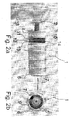
- the housing 5 comprises at its circumferential wall near the base 4 a marking 10.
- This marking 10 comprises a number of stripes 11-13. These stripes 11-13 are colored. For example, the stripe 11 nearest to the base 4 is blue and the stripe 13 farthest from the base 4 is red and the stripe 12 has a color between blue and red.
- the colors of the stripes 11-13 correspond to the colors of the scale 8. In order to keep the drawing simple, only three stripes are shown. However, the number of stripes should correspond to the number of colors of the scale.
- the marking 10 can comprise haptic symbols.
- Such symbols can have the form of small depressions or protrusions. In this case a person can use his fingers to feel the extent to which the turning handle has been moved away from the base. Even if the thermostat is completely invisible, the person can still obtain the information about the set temperature.
- the turning handle 6 When the set temperature of the thermostat head 1 is to be changed, the turning handle 6 is rotated around the axis 7.
- the gearing means for example a screw like guiding means between the housing 5 and the turning handle 6 causes a translational movement of the turning handle 6 away from a base 4 or (turned into the other direction) in a direction towards the base 4.
- an edge 14 of the turning handle 6 nearest to the base 4 covers or gives free one or more of the stripes 11, 12, 13.
- the edge uncovers the blue stripe 11 at the beginning, when the set temperature is further increased, the intermediate stripe 12 is uncovered. At the highest set temperature the red stripe 13 is uncovered as well.
- the marking 10 can be seen in side view.
- the marking 10 surrounds the housing completely, i.e. the marking is visible in the position of the turning handle 6 shown in Fig. 2a independently of the viewing angle of a person looking to the thermostat head 1.
- the person turning the turning handle 6 in order to set a value for a temperature to be controlled in the room heated by the radiator 3 now has two possibilities to check the set temperature.
- the first possibility is to look to the front face.
- the pointer 9 in connection with the scale 8 gives an information about the set temperature.
- a further possibility is given with the marking 10 which is more or less covered by the turning handle 6.
- the gearing has a non-linear transmission ratio. This means that a translational movement of the turning handle is not proportional to the rotational movement.
- the translational movement can be less than the translational movement of the turning handle 6 when the turning handle 6 is rotated from a set temperature of 22 °C to a set temperature of 24 °C.
- a higher set temperature can be more clearly visualized.
Landscapes
- Engineering & Computer Science (AREA)
- Physics & Mathematics (AREA)
- Chemical & Material Sciences (AREA)
- Thermal Sciences (AREA)
- Combustion & Propulsion (AREA)
- Mechanical Engineering (AREA)
- General Engineering & Computer Science (AREA)
- General Physics & Mathematics (AREA)
- Automation & Control Theory (AREA)
- Fluid Mechanics (AREA)
- Indication Of The Valve Opening Or Closing Status (AREA)
- Mechanically-Actuated Valves (AREA)
- Temperature-Responsive Valves (AREA)
Abstract
Description
- The present invention relates to a thermostat head for a valve, in particular a radiator valve, comprising a base, a housing connected to said base, a turning handle mounted to said housing, wherein said turning handle is rotatable around an axis, and a scale indicating an angular position of said turning handle relative to said housing.
- Such a thermostat head is commonly known and, for example, described in
DE 43 20 103 A1 . It is used to adjust a set value for a room temperature of a room to be heated by a radiator. Usually, a thermostat element is accommodated in the thermostat head and opens or closes the radiator valve depending on the actual room temperature. - The set temperature to be reached in the room is indicated by a scale. An example of such a scale shows a sequence of numbers, e.g. 1, 2, 3, 4, 5, on a front face of the housing, and the turning handle shows a pointer, for example a point, which is positioned near the circle of numbers so that the set temperature is visualized on the front face of the thermostat head.
- However, in some cases it is rather difficult to inspect the front face of the thermostat head. In such cases an uncomfortable situation can arrive in which the temperature of the room is too low or too high.
- The object of the invention is to allow control of the set temperature in a simple manner.
- This object is solved in a thermostat head described at the outset in that a gearing is provided translating a rotational movement of said turning handle into a translation movement of said turning handle in a direction parallel to said axis, wherein a marking is provided showing an axial position of said turning handle relative to said base.
- Such a thermostat head shows the set temperature in two different ways. A first information about the set temperature can be gained from the scale indicating the angular position of the turning handle. A second information can be gained from the marking showing the axial position of the turning handle relative to said base. It is rather unlikely that a person in a room to be heated is not able to obtain at least one of these two informations. Since both informations have the same content it does not matter whether the person can control the set temperature by means of the scale or by means of the marking.
- Preferably said marking is visible in a side view of said thermostat head. In this case, the information about the set temperature can be obtained by looking to the front or looking to the side of the thermostat head.
- Preferably said marking shows a distance between said base and said turning handle. The distance can easily be shown and gives an unique information about the axial position of the turning handle relative to the base.
- Preferably said marking is fixed to said housing. The housing is stationary. Therefore, the marking is stationary as well.
- Preferably said marking is positioned between an end of said turning handle next to said base and said base. The turning handle does not need any opening or other modifications. It can simply have the form of a cup. This allows a production with low costs.
- Preferably said marking is positioned on a circumferential wall of said housing. The turning handle surrounds a circumferential wall of said housing. When the turning handle is moved axially, the marking on the circumferential wall of the housing is visible to a greater or smaller extend.
- Preferably said marking surrounds said housing. In this case the marking is visible over the entire circumference of the thermostat head.
- In a preferred embodiment said marking comprises different colors. Colors are easy to identify by a person in a room. They give reliable information even if there is limited space only.
- In a preferred embodiment colors of the marking correspond to colors on said scale. In other words, the person gets the same color information independently whether the person looks to the front face of the thermostat head or to the circumferential wall.
- In a preferred embodiment said marking comprises a predetermined number of stripes. The use of stripes allows for a simple identification of the set temperature as well.
- In this case it is preferred that said stripes have different colors.
- In a preferred embodiment a position of said turning handle near said base indicates a low set temperature and a position of said turning handle farther from said base indicates a higher set temperature, wherein an area with a blue color is positioned near said base and an area with a red color is positioned farther from said base. A blue color is usually assigned to a low temperature and a red color is usually assigned to a high temperature. Using blue and red colors allow for a simple overview over the set temperature.
- In a preferred embodiment a further colored area is arranged between said blue colored area and said red colored area. In this case more than the two mentioned colors blue and red are available for producing the desired information.
- Preferably said marking comprises haptic symbols. In this case it is possible for a person to feel the extent to which the turning handle has been moved away from the base.
- Furthermore, it is preferred that said gearing has a non-linear transmission ratio. In other words, it can be realized that the translational movement of the turning handle related to the rotational movement is larger in certain angle areas, for example in the region of a higher set temperature. In this case it is possible to show more clearly that a high set temperature has been adjusted.
- A preferred embodiment of the invention will now be described in more detail with reference to the drawing, wherein:
- Fig. 1
- shows a thermostat head for a radiator valve with a low set temperature and
- Fig. 2
- shows the thermostat head with a higher set temperature.
-
Fig. 1 shows athermostat head 1 for aradiator valve 2. Theradiator valve 2 is part of aradiator 3 which is used to heat a room (not shown) as it is known in the art. - The
thermostat head 1 comprises abase 4, ahousing 5 connected to saidbase 4 and aturning handle 6 mounted to said housing. Theturning handle 6 is rotatable around anaxis 7 which is the middle axis of thehousing 5. - The
housing 5, at its front face, comprises ascale 8. In the present case, thescale 8 shows a sequence of thenumbers 1 to 5 arranged in a circular form. Furthermore, thescale 8 shows different colors. For example, a region around thenumber 1 is colored in blue and a region around thenumber 5 is colored in red. Between the blue colored region and the red colored region the gap is filled with a colored area changing the color from blue to red. However, the expression scale is not limited to numbers, but can mean a field of different colors, other symbols or the like. - The
turning handle 6 comprises apointer 9, for example a point. Thepointer 9 indicates the angular position of the turning handle 6 relative to thehousing 5. - When the
pointer 9 is positioned at the position of thenumber 1 of thescale 8 it is indicated that the set temperature is e.g. 16° C. When thepointer 9 is positioned near thenumber 5 it is indicated that the set temperature is e.g. 24° C. - However, the front face of the thermostat head shown in
Fig. 1b is not always visible. In order to provide a user with the necessary information, the thermostat head is provided with an additional marking showing the set temperature. - To this end a gearing is provided translating a rotational movement of the turning handle 6 into a translational movement of the turning handle 6 parallel to the
axis 7. Such a gearing can be realized by means of a screw drive, for example. - The
housing 5 comprises at its circumferential wall near the base 4 amarking 10. This marking 10 comprises a number of stripes 11-13. These stripes 11-13 are colored. For example, thestripe 11 nearest to thebase 4 is blue and thestripe 13 farthest from thebase 4 is red and thestripe 12 has a color between blue and red. The colors of the stripes 11-13 correspond to the colors of thescale 8. In order to keep the drawing simple, only three stripes are shown. However, the number of stripes should correspond to the number of colors of the scale. - Additionally or alternatively the marking 10 can comprise haptic symbols. Such symbols can have the form of small depressions or protrusions. In this case a person can use his fingers to feel the extent to which the turning handle has been moved away from the base. Even if the thermostat is completely invisible, the person can still obtain the information about the set temperature.
- When the set temperature of the
thermostat head 1 is to be changed, the turning handle 6 is rotated around theaxis 7. The gearing means, for example a screw like guiding means between thehousing 5 and the turning handle 6 causes a translational movement of the turning handle 6 away from abase 4 or (turned into the other direction) in a direction towards thebase 4. In this way anedge 14 of the turning handle 6 nearest to thebase 4 covers or gives free one or more of thestripes blue stripe 11 at the beginning, when the set temperature is further increased, theintermediate stripe 12 is uncovered. At the highest set temperature thered stripe 13 is uncovered as well. - The marking 10 can be seen in side view. The marking 10 surrounds the housing completely, i.e. the marking is visible in the position of the turning handle 6 shown in
Fig. 2a independently of the viewing angle of a person looking to thethermostat head 1. - The person turning the turning handle 6 in order to set a value for a temperature to be controlled in the room heated by the
radiator 3 now has two possibilities to check the set temperature. The first possibility is to look to the front face. Here thepointer 9 in connection with thescale 8 gives an information about the set temperature. A further possibility is given with the marking 10 which is more or less covered by the turninghandle 6. - In a preferred embodiment the gearing has a non-linear transmission ratio. This means that a translational movement of the turning handle is not proportional to the rotational movement. When, for example, the turning handle 6 is rotated from a set temperature of 18 °C to a set temperature of 20 °C the translational movement can be less than the translational movement of the turning handle 6 when the turning handle 6 is rotated from a set temperature of 22 °C to a set temperature of 24 °C. Using such a nonlinear transmission ratio, a higher set temperature can be more clearly visualized.
Claims (15)
- Thermostat head (1) for a valve (2) comprising a base (4), a housing (5) connected to said base (4), a turning handle (6) mounted to said housing (5), wherein said turning handle (6) is rotatable around an axis (7), and a scale (8) indicating an angular position of said turning handle (6) relative to said housing (5), characterized in that a gearing is provided translating a rotational movement of said turning handle (6) into a translational movement of said turning handle (6) in a direction parallel to said axis (7), wherein a marking (10) is provided showing an axial position of said turning handle (6) relative to said base (4).
- Thermostat head according to claim 1, characterized in that said marking (10) is visible in a side view of said thermostat head (1).
- Thermostat head according to claim 1 or 2, characterized in that said marking (10) shows a distance between said base (4) and said turning handle (6).
- Thermostat head according to any of claims 1 to 3, characterized in that said marking (10) is fixed to said housing (5).
- Thermostat head according to claim 4, characterized in that said marking (10) is positioned between an end (14) of said turning handle (6) next to said base (4) and said base (4).
- Thermostat head according to any of claims 1 to 5, characterized in that said marking (10) is positioned on a circumferential wall of said housing (5).
- Thermostat head according to claim 6, characterized in that said marking (10) surrounds said housing (5).
- Thermostat head according to any of claims 1 to 7, characterized in that said marking (10) comprises different colors.
- Thermostat head according to claim 8, characterized in that colors of the marking (10) correspond to colors of said scale (8).
- Thermostat head according to any of claims 1 to 9, characterized in that said marking (10) comprises a predetermined number of stripes (11-13).
- Thermostat head according to claim 10, characterized in that said stripes (11-13) have different colors.
- Thermostat head according to claim 8 to 11, characterized in that a position of said turning handle (6) near said base (4) indicates a low set temperature and a position of said turning handle (6) farther from said base (4) indicates a higher set temperature, wherein an area with a blue color is positioned near said base (4) and an area with a red color is positioned farther from said base (4).
- Thermostat head according to claim 12, characterized in that a further colored area is arranged between said blue colored area and said red colored area.
- Thermostat head according to any of claims 1 to 13, characterized in that said marking (10) comprises haptic symbols.
- Thermostat head according to any of claims 1 to 14, characterized in that said gearing has a non-linear transmission ratio.
Priority Applications (3)
| Application Number | Priority Date | Filing Date | Title |
|---|---|---|---|
| EP14151549.4A EP2896860A1 (en) | 2014-01-17 | 2014-01-17 | Thermostat head for a valve, in particular a radiator valve |
| CN201420717039.0U CN204331494U (en) | 2014-01-17 | 2014-11-25 | For the temperature controller head of valve |
| UAA201413717A UA113009C2 (en) | 2014-01-17 | 2014-12-22 | THERMOSTATIC HEAD FOR VALVE, INCLUDING FOR RADIATOR VALVE |
Applications Claiming Priority (1)
| Application Number | Priority Date | Filing Date | Title |
|---|---|---|---|
| EP14151549.4A EP2896860A1 (en) | 2014-01-17 | 2014-01-17 | Thermostat head for a valve, in particular a radiator valve |
Publications (1)
| Publication Number | Publication Date |
|---|---|
| EP2896860A1 true EP2896860A1 (en) | 2015-07-22 |
Family
ID=49958297
Family Applications (1)
| Application Number | Title | Priority Date | Filing Date |
|---|---|---|---|
| EP14151549.4A Withdrawn EP2896860A1 (en) | 2014-01-17 | 2014-01-17 | Thermostat head for a valve, in particular a radiator valve |
Country Status (3)
| Country | Link |
|---|---|
| EP (1) | EP2896860A1 (en) |
| CN (1) | CN204331494U (en) |
| UA (1) | UA113009C2 (en) |
Citations (7)
| Publication number | Priority date | Publication date | Assignee | Title |
|---|---|---|---|---|
| DD37034A (en) * | ||||
| DE2148967A1 (en) * | 1971-09-30 | 1973-04-05 | Samson Appbau Ag | ADJUSTABLE KNOB FOR REGULATING DEVICES |
| DE4320103A1 (en) | 1992-06-17 | 1993-12-23 | Drayton Controls Engineering L | Thermostats and radiator thermostatic valves |
| DE29704809U1 (en) * | 1997-03-14 | 1997-05-22 | Herz Armaturen Ges.M.B.H., Wien | Setting device for regulating or control devices, in particular setting head for thermostatic valves |
| DE10049928A1 (en) * | 2000-10-06 | 2002-05-02 | F W Oventrop Gmbh & Co Kg | Hand grip knob for a thermostatically controlled valve has a number scale that can be fitted in different positions |
| DE102007055516A1 (en) * | 2007-11-21 | 2009-06-04 | Theodor Heimeier Metallwerk Gmbh | Cap-shaped rotary handle for thermostatic valve in heating or cooling system, has single piece part rotatable opposite to handle, where part has readable elements or numerals on display on visible peripheral surface and/or outer surface |
| DE202011004240U1 (en) * | 2011-03-22 | 2011-08-30 | Alexander Altstötter | Heating device with air freshener |
-
2014
- 2014-01-17 EP EP14151549.4A patent/EP2896860A1/en not_active Withdrawn
- 2014-11-25 CN CN201420717039.0U patent/CN204331494U/en not_active Expired - Fee Related
- 2014-12-22 UA UAA201413717A patent/UA113009C2/en unknown
Patent Citations (7)
| Publication number | Priority date | Publication date | Assignee | Title |
|---|---|---|---|---|
| DD37034A (en) * | ||||
| DE2148967A1 (en) * | 1971-09-30 | 1973-04-05 | Samson Appbau Ag | ADJUSTABLE KNOB FOR REGULATING DEVICES |
| DE4320103A1 (en) | 1992-06-17 | 1993-12-23 | Drayton Controls Engineering L | Thermostats and radiator thermostatic valves |
| DE29704809U1 (en) * | 1997-03-14 | 1997-05-22 | Herz Armaturen Ges.M.B.H., Wien | Setting device for regulating or control devices, in particular setting head for thermostatic valves |
| DE10049928A1 (en) * | 2000-10-06 | 2002-05-02 | F W Oventrop Gmbh & Co Kg | Hand grip knob for a thermostatically controlled valve has a number scale that can be fitted in different positions |
| DE102007055516A1 (en) * | 2007-11-21 | 2009-06-04 | Theodor Heimeier Metallwerk Gmbh | Cap-shaped rotary handle for thermostatic valve in heating or cooling system, has single piece part rotatable opposite to handle, where part has readable elements or numerals on display on visible peripheral surface and/or outer surface |
| DE202011004240U1 (en) * | 2011-03-22 | 2011-08-30 | Alexander Altstötter | Heating device with air freshener |
Non-Patent Citations (1)
| Title |
|---|
| DANFOSS: "Thermostatic sensors type RA 2000", 1 September 2003 (2003-09-01), XP055418576, Retrieved from the Internet <URL:http://www.uk-plumbing.com/brochure/danfoss/RA2000Data.pdf> [retrieved on 20171024] * |
Also Published As
| Publication number | Publication date |
|---|---|
| CN204331494U (en) | 2015-05-13 |
| UA113009C2 (en) | 2016-11-25 |
Similar Documents
| Publication | Publication Date | Title |
|---|---|---|
| USD969857S1 (en) | Display screen or portion thereof with graphical user interface | |
| USD785128S1 (en) | Targeting display for a rangefinder, riflescope, or other aimed optical device | |
| US8875435B2 (en) | Actuator for setting at least one optical property | |
| US10417826B2 (en) | Information input method in 3D immersive environment | |
| USD839290S1 (en) | Display screen with graphical user interface | |
| MY180322A (en) | Optically variable element | |
| WO2017195026A3 (en) | Heads-up display with variable image plane | |
| CN106264106A (en) | Insulating pot and the method being used for adding hot water | |
| WO2014166922A3 (en) | Injection device | |
| AU2016206210A1 (en) | Food processor and method for operating a food processor | |
| EP2848887A3 (en) | Adjustment turret with indication of the number of revolutions | |
| USD858533S1 (en) | Computing device display screen with graphical user interface for providing geographic-specific service information | |
| US20140063278A1 (en) | Remote control unit for an objective and for a camera | |
| WO2019126700A3 (en) | Knife accessory for hot stick | |
| JP6996693B2 (en) | A communication system for transmitting information items of a detected object between at least two communication partners. | |
| EP3321760A3 (en) | User interface for a thermostat | |
| US20170241744A1 (en) | Sighting device | |
| US20130182411A1 (en) | Tangible navigation of color temperature and light intensity | |
| JP2017059212A5 (en) | ||
| JP6835832B2 (en) | Open and / or closed indicator of tap or decompressor | |
| GB2577274B (en) | Automated text layout, colour and other stylization on an image or video, and the tracking and application of user color preferences | |
| EP3364111A3 (en) | Rotary knob assembly with display | |
| CN204331494U (en) | For the temperature controller head of valve | |
| EP2746889B1 (en) | A method and an adjusting tool for adjusting a presetting of a valve, in particular a heat exchanger valve | |
| US8325136B2 (en) | Computer display pointer device for a display |
Legal Events
| Date | Code | Title | Description |
|---|---|---|---|
| PUAI | Public reference made under article 153(3) epc to a published international application that has entered the european phase |
Free format text: ORIGINAL CODE: 0009012 |
|
| 17P | Request for examination filed |
Effective date: 20140117 |
|
| AK | Designated contracting states |
Kind code of ref document: A1 Designated state(s): AL AT BE BG CH CY CZ DE DK EE ES FI FR GB GR HR HU IE IS IT LI LT LU LV MC MK MT NL NO PL PT RO RS SE SI SK SM TR |
|
| AX | Request for extension of the european patent |
Extension state: BA ME |
|
| 17P | Request for examination filed |
Effective date: 20151010 |
|
| RBV | Designated contracting states (corrected) |
Designated state(s): AL AT BE BG CH CY CZ DE DK EE ES FI FR GB GR HR HU IE IS IT LI LT LU LV MC MK MT NL NO PL PT RO RS SE SI SK SM TR |
|
| STAA | Information on the status of an ep patent application or granted ep patent |
Free format text: STATUS: EXAMINATION IS IN PROGRESS |
|
| 17Q | First examination report despatched |
Effective date: 20171027 |
|
| GRAP | Despatch of communication of intention to grant a patent |
Free format text: ORIGINAL CODE: EPIDOSNIGR1 |
|
| STAA | Information on the status of an ep patent application or granted ep patent |
Free format text: STATUS: GRANT OF PATENT IS INTENDED |
|
| INTG | Intention to grant announced |
Effective date: 20180524 |
|
| STAA | Information on the status of an ep patent application or granted ep patent |
Free format text: STATUS: THE APPLICATION IS DEEMED TO BE WITHDRAWN |
|
| 18D | Application deemed to be withdrawn |
Effective date: 20181005 |