EP2896828A1 - Wind turbine generator - Google Patents
Wind turbine generator Download PDFInfo
- Publication number
- EP2896828A1 EP2896828A1 EP13875197.9A EP13875197A EP2896828A1 EP 2896828 A1 EP2896828 A1 EP 2896828A1 EP 13875197 A EP13875197 A EP 13875197A EP 2896828 A1 EP2896828 A1 EP 2896828A1
- Authority
- EP
- European Patent Office
- Prior art keywords
- rotor shaft
- drivetrain
- circumferential surface
- oscillation
- generator
- Prior art date
- Legal status (The legal status is an assumption and is not a legal conclusion. Google has not performed a legal analysis and makes no representation as to the accuracy of the status listed.)
- Granted
Links
- 230000010355 oscillation Effects 0.000 claims abstract description 54
- 230000001902 propagating effect Effects 0.000 claims abstract description 6
- 230000003534 oscillatory effect Effects 0.000 description 24
- 238000005452 bending Methods 0.000 description 23
- 238000013016 damping Methods 0.000 description 8
- 230000000903 blocking effect Effects 0.000 description 6
- 230000001603 reducing effect Effects 0.000 description 6
- 230000005855 radiation Effects 0.000 description 5
- 238000010586 diagram Methods 0.000 description 4
- 230000005540 biological transmission Effects 0.000 description 3
- 230000000052 comparative effect Effects 0.000 description 3
- XEEYBQQBJWHFJM-UHFFFAOYSA-N Iron Chemical compound [Fe] XEEYBQQBJWHFJM-UHFFFAOYSA-N 0.000 description 2
- 230000007423 decrease Effects 0.000 description 2
- 230000000694 effects Effects 0.000 description 2
- 230000005284 excitation Effects 0.000 description 2
- 239000000463 material Substances 0.000 description 2
- 238000000034 method Methods 0.000 description 2
- 238000007796 conventional method Methods 0.000 description 1
- 230000003247 decreasing effect Effects 0.000 description 1
- 229910052742 iron Inorganic materials 0.000 description 1
- 239000002184 metal Substances 0.000 description 1
- 229910052751 metal Inorganic materials 0.000 description 1
- 239000007769 metal material Substances 0.000 description 1
- 238000012986 modification Methods 0.000 description 1
- 230000004048 modification Effects 0.000 description 1
- 238000004321 preservation Methods 0.000 description 1
- 238000003466 welding Methods 0.000 description 1
Images



Classifications
-
- F—MECHANICAL ENGINEERING; LIGHTING; HEATING; WEAPONS; BLASTING
- F03—MACHINES OR ENGINES FOR LIQUIDS; WIND, SPRING, OR WEIGHT MOTORS; PRODUCING MECHANICAL POWER OR A REACTIVE PROPULSIVE THRUST, NOT OTHERWISE PROVIDED FOR
- F03D—WIND MOTORS
- F03D13/00—Assembly, mounting or commissioning of wind motors; Arrangements specially adapted for transporting wind motor components
- F03D13/20—Arrangements for mounting or supporting wind motors; Masts or towers for wind motors
-
- F—MECHANICAL ENGINEERING; LIGHTING; HEATING; WEAPONS; BLASTING
- F03—MACHINES OR ENGINES FOR LIQUIDS; WIND, SPRING, OR WEIGHT MOTORS; PRODUCING MECHANICAL POWER OR A REACTIVE PROPULSIVE THRUST, NOT OTHERWISE PROVIDED FOR
- F03D—WIND MOTORS
- F03D15/00—Transmission of mechanical power
-
- F—MECHANICAL ENGINEERING; LIGHTING; HEATING; WEAPONS; BLASTING
- F03—MACHINES OR ENGINES FOR LIQUIDS; WIND, SPRING, OR WEIGHT MOTORS; PRODUCING MECHANICAL POWER OR A REACTIVE PROPULSIVE THRUST, NOT OTHERWISE PROVIDED FOR
- F03D—WIND MOTORS
- F03D9/00—Adaptations of wind motors for special use; Combinations of wind motors with apparatus driven thereby; Wind motors specially adapted for installation in particular locations
- F03D9/20—Wind motors characterised by the driven apparatus
- F03D9/25—Wind motors characterised by the driven apparatus the apparatus being an electrical generator
-
- F—MECHANICAL ENGINEERING; LIGHTING; HEATING; WEAPONS; BLASTING
- F05—INDEXING SCHEMES RELATING TO ENGINES OR PUMPS IN VARIOUS SUBCLASSES OF CLASSES F01-F04
- F05B—INDEXING SCHEME RELATING TO WIND, SPRING, WEIGHT, INERTIA OR LIKE MOTORS, TO MACHINES OR ENGINES FOR LIQUIDS COVERED BY SUBCLASSES F03B, F03D AND F03G
- F05B2260/00—Function
- F05B2260/96—Preventing, counteracting or reducing vibration or noise
-
- F—MECHANICAL ENGINEERING; LIGHTING; HEATING; WEAPONS; BLASTING
- F05—INDEXING SCHEMES RELATING TO ENGINES OR PUMPS IN VARIOUS SUBCLASSES OF CLASSES F01-F04
- F05B—INDEXING SCHEME RELATING TO WIND, SPRING, WEIGHT, INERTIA OR LIKE MOTORS, TO MACHINES OR ENGINES FOR LIQUIDS COVERED BY SUBCLASSES F03B, F03D AND F03G
- F05B2260/00—Function
- F05B2260/96—Preventing, counteracting or reducing vibration or noise
- F05B2260/964—Preventing, counteracting or reducing vibration or noise by damping means
-
- Y—GENERAL TAGGING OF NEW TECHNOLOGICAL DEVELOPMENTS; GENERAL TAGGING OF CROSS-SECTIONAL TECHNOLOGIES SPANNING OVER SEVERAL SECTIONS OF THE IPC; TECHNICAL SUBJECTS COVERED BY FORMER USPC CROSS-REFERENCE ART COLLECTIONS [XRACs] AND DIGESTS
- Y02—TECHNOLOGIES OR APPLICATIONS FOR MITIGATION OR ADAPTATION AGAINST CLIMATE CHANGE
- Y02E—REDUCTION OF GREENHOUSE GAS [GHG] EMISSIONS, RELATED TO ENERGY GENERATION, TRANSMISSION OR DISTRIBUTION
- Y02E10/00—Energy generation through renewable energy sources
- Y02E10/70—Wind energy
- Y02E10/72—Wind turbines with rotation axis in wind direction
-
- Y—GENERAL TAGGING OF NEW TECHNOLOGICAL DEVELOPMENTS; GENERAL TAGGING OF CROSS-SECTIONAL TECHNOLOGIES SPANNING OVER SEVERAL SECTIONS OF THE IPC; TECHNICAL SUBJECTS COVERED BY FORMER USPC CROSS-REFERENCE ART COLLECTIONS [XRACs] AND DIGESTS
- Y02—TECHNOLOGIES OR APPLICATIONS FOR MITIGATION OR ADAPTATION AGAINST CLIMATE CHANGE
- Y02E—REDUCTION OF GREENHOUSE GAS [GHG] EMISSIONS, RELATED TO ENERGY GENERATION, TRANSMISSION OR DISTRIBUTION
- Y02E10/00—Energy generation through renewable energy sources
- Y02E10/70—Wind energy
- Y02E10/728—Onshore wind turbines
Definitions
- the present disclosure relates to a wind turbine power generating apparatus.
- a wind turbine power generating apparatus includes a tower of a predetermined height and a nacelle disposed on the top of the tower.
- the nacelle includes a generator and a speed-increasing unit. At least one blade rotated by wind power is mounted to the nacelle, so that the generator is driven by the rotation force of the blade serving as a driving force to generate electric power.
- noise may be produced from oscillation which occurs during operation of a generator or a speed-increasing unit and propagates in the form of waves on the wall surface of a tower, the wall surface serving as an oscillation plate.
- Patent Document 1 discloses a technique of providing a plurality of blocking masses in a tower. The blocking masses reduce propagation of oscillation which has a frequency corresponding to a property of the blocking masses such as the size, which makes it possible to reduce the operation noise.
- Patent Document 1 Japanese Patent Application Pub. No. 3342148
- the blocking masses are effective in reducing propagation of oscillation, the shape of the blocking masses need to be determined so that the rotation shaft is not decentered in a case where the blocking masses are provided for a rotational body.
- an object of at least one embodiment of the present invention is to provide a novel and improved wind turbine power generating apparatus capable of reducing structural borne sound due to oscillatory propagation of a particular frequency, with a simplified configuration.
- a wind turbine power generating apparatus includes: a nacelle supported on a tower; a rotor which includes a blade for receiving wind power, the rotor being configured to rotate upon receiving wind at the blade; a rotor shaft coupled to the rotor and supported rotatably on the nacelle; a generator which generates electric power from rotational force of the rotor shaft; and at least two rigidity-enhancing parts disposed on an inner circumferential surface or an outer circumferential surface of at least one of the rotor shaft or the tower, at an interval which is set so as to correspond to a frequency of oscillation caused during operation of the generator, or oscillation caused during operation of a drivetrain for transmitting the rotational force of the rotor shaft to the generator in a case where the drivetrain is provided.
- the at least two rigidity-enhancing parts are arranged in a propagating direction of the oscillation.
- the frequency of oscillation that is to be reduced in accordance with the interval between the at least two rigidity-enhancing parts is set corresponding to the frequency of the oscillation generated during operation of the generator or during operation of the drivetrain.
- the rigidity-enhancing parts include at least one of a rib member disposed on the inner circumferential surface or the outer circumferential surface, a bearing of the rotor shaft, or a flange.
- the bearing of the rotor shaft, or the flange makes it possible to reduce the oscillatory propagation of a bending wave generated by oscillation of the generator or the drivetrain with a simplified structure.
- the bearing of the rotor shaft or the flange it is possible to reduce the number of members to be additionally provided, which makes it possible to reduce the oscillatory propagation of a bending wave generated by oscillation of the generator or the drivetrain with a simplified structure.
- the drivetrain includes a hydraulic pump configured to be driven by rotation of the rotor shaft, and a hydraulic motor configured to be driven by pressurized oil generated in the hydraulic pump and to enable the generator to generate electric power.
- a novel and improved wind turbine power generating apparatus capable of reducing the structural borne sound due to oscillatory propagation of a specific frequency with a simplified structure.
- FIG. 1 is a diagram of an overall configuration of a wind turbine power generating apparatus according to one embodiment of the present invention.
- FIG. 2 is a detail view of an exemplary configuration of the wind turbine power generating apparatus according to one embodiment of the present invention.
- the wind turbine power generating apparatus 100 includes a rotor 102 which rotates upon receiving wind, a nacelle 105 which rotatably supports a rotor shaft 106 of the rotor 102, a drivetrain 107 for increasing the rotation speed of the rotor shaft 106, a tower 111 of a substantially cylindrical shape supporting the nacelle 105, and a generator 114 which generates electric power.
- the nacelle 105 is capable of yaw rotating about the tower 111.
- the rotor 102 includes at least one blade 103 and a hub 104 to which the blade 103 is mounted.
- the rotor shaft 106 is mounted to the hub 104, and the rotor 102 is rotated with the rotor shaft 106 by the wind power received at the blade 103. This rotation is inputted into the drivetrain 107 via the rotor shaft 106.
- the hub 104 may be covered by a hub cover 104a.
- the drivetrain 107 is a speed-increasing unit for increasing the rotation speed of the rotor shaft 106 and inputting the rotation to the generator 114.
- the drivetrain 107 includes a hydraulic pump 110 coupled to the rotor shaft 106, a hydraulic motor 112 coupled to the generator 114, and oil circulation lines disposed between the hydraulic pump 110 and the hydraulic motor 112.
- the circulation lines include a high pressure oil line 116 and a low pressure oil line 118.
- the high pressure oil line 116 connects an outlet side of the hydraulic pump 110 and an inlet side of the hydraulic motor 112, while the low pressure oil line 118 connects an inlet side of the hydraulic pump 110 and an outlet side of the hydraulic motor 112.
- the hydraulic pump 110 is driven by the rotor shaft 106 to generate high pressure working oil.
- the high pressure working oil is supplied to the hydraulic motor 112 through the high pressure oil line 116, and then drives the hydraulic motor 112.
- the generator 114 coupled to the hydraulic motor 112 is driven to generate electric power.
- the working oil having been discharged from the hydraulic motor 112 is supplied to the hydraulic pump 110 through the low pressure oil line 118, has its pressure increased in the hydraulic pump 110, and then returns to the hydraulic motor 112.
- the drivetrain 107 is a hydraulic transmission described above, though the drivetrain may be a gearbox including planetary gears or the like. In recent years, however, the wind turbine power generating apparatus 100 has increased in size. Thus, a hydraulic transmission is more preferable as the drivetrain 107 being a speed-increasing mechanism, because more weight can be reduced in a hydraulic transmission than in a gearbox.
- the rotor shaft 106 is a hollow member of a substantially cylindrical shape including rigid metal material such as iron.
- the rotor shaft 106 includes, as illustrated in FIG. 2 , two rib members 122 serving as rigidity-enhancing parts 120 for improving rigidity of the rotor shaft 106, on the inner circumferential surface 106a of the rotor shaft 106.
- the number of the rib members 122 is at least two, and the rib members 122 are arranged at an interval which is set corresponding to the frequency of oscillation caused during operation of the hydraulic pump 110 of the drivetrain 107, in the propagating direction of the oscillation.
- the inner circumferential surface 106a is fixed so as not to oscillate at positions where the rib members 122 are disposed. As a result, it is possible to reduce the structural borne sound due to the oscillatory propagation from the hydraulic pump 110.
- rib members 122 While two rib members 122 are disposed on the inner circumferential surface 106a of the rotor shaft 106 in the embodiment illustrated in FIG. 2 , it is sufficient if the number of the rib members 122 is at least two. Thus, three or more rib members 122 may be provided.
- a flange 126 disposed on an end of the outer circumferential surface 106b of the rotor shaft 106 or a bearing 124 for supporting the rotor shaft 106 rotatably may be employed as the rigidity-enhancing parts 120. That is, in addition to attaching the rib members 122 to the rotor shaft 106, the existing bearing 124 and flange 126 may be also employed as the rigidity-enhancing parts 120 because the bearing 124 and the flange 126 are also capable of preventing oscillation of the outer circumferential surface 106b of the rotor shaft 106.
- utilizing the bearing 124 and the flange 126 of the rotor shaft 106 makes it possible to reduce the number of members to be additionally attached, and to reduce oscillatory propagation of a bending wave caused by oscillation of the drivetrain 107 with more simplified configuration.
- the rib members 122 may be disposed on the outer circumferential surface 106b of the rotor shaft 106. That is, to reduce the structural borne sound due to oscillatory propagation from the drivetrain 107, it is sufficient if there are at least two rib members 122 being the rigidity-enhancing parts 120 disposed on at least one of the inner circumferential surface 106a or the outer circumferential surface 106b of the rotor shaft 106.
- FIG. 3 is a diagram of an exemplary configuration of rigidity-enhancing parts of the wind turbine power generating apparatus according to one embodiment of the present invention.
- rib members 122 of an annular shape are additionally disposed on the inner circumferential surface 106a of the rotor shaft 106 being a hollow cylindrical member at a predetermined interval L to reduce oscillatory propagation of a bending wave with a specific frequency.
- the rib members 122 include a rigid material such as metal.
- the attachment structure of the rib members 122 may include an attachment structure in which an annular member is inserted into the rotor shaft 106, an attachment structure in which a plate member is bended and inserted into the rotor shaft 106, or an attachment structure in which welding is overlaid at positions where the rib members 122 are to be disposed.
- the inner circumferential surface 106a is fixed so as not to oscillate at positions where the rib members 122 are disposed.
- a bending wave W1 of oscillation having a node P1 at one of the rib members 122 passes through as illustrated in FIG. 4
- a bending wave W2 of oscillation having an antinode, not a node, at one of the rib members 122 is blocked, as illustrated in FIG. 5 .
- the oscillation frequencies (excitation frequencies) of the drivetrain 107 include a number of frequencies, and each of the excitation frequencies has a bending wave that tries to propagate through the rotor shaft 106.
- the rib members 122 constitute the support part or the fixation part of the rotor shaft 106, a bending wave having nodes at the rib members 122 easily propagates on the rotor shaft 106, while a wave having no node at the rib members 122 has larger damping, which makes it possible to reduce oscillation.
- the interval L of the rib members 122 being the rigidity-enhancing parts 120 is determined from a specific frequency of a bending wave whose oscillatory propagation is desired to be reduced, and accordingly, the rib members 122 are additionally provided.
- the main source of oscillation of the drivetrain 107 is the hydraulic pump 110, and the oscillation frequency caused during operation of the hydraulic pump 110 is within the range of from not less than 300Hz to not more than 400Hz.
- the interval of the rib members 122 is determined to be a value of approximately 1 to 2m from the above relationship.
- the wavelength ⁇ which brings about a reducing effect of oscillatory propagation from the drivetrain 107, is a wavelength which does not have nodes at the rib members 122.
- the interval L of the rib members 122 is adjusted so as to achieve the above effect.
- a drivetrain such as a gearbox and a hydraulic drive
- Oscillation due to a drivetrain in particular is one of the generation sources of the operation noise, because oscillation of a gearbox, a hydraulic drive or the like transmits to each part of the blade or the like by propagating on a rotor shaft, a rotor head, or the like.
- the rib members 122 are attached to the inner circumferential surface 106a of the rotor shaft 106 at the above interval L, and in the propagating direction of the oscillation, so that the inner circumferential surface 106 is fixed at positions where the rib members 122 are disposed, so as not to oscillate due to oscillatory propagation from the drivetrain 107.
- providing the rib members 122 reduces the structural borne sound due to the oscillatory propagation from the drivetrain 107 to the rotor shaft 106.
- the drivetrain 107 such as a gearbox and a hydraulic pump produces oscillation at a specific frequency. Thus, it is unnecessary to reduce oscillation over the entire range of the frequencies.
- a technique is employed such that the rib members 122 being the rigidity-enhancing parts 120 are disposed on the rotor shaft 106 at the above described specific interval to reduce the oscillation level of a specific frequency, which enables tuning of a specific frequency.
- the rib members 122 are disposed on the rotor shaft 106 to reduce the oscillation level of a specific frequency due to oscillation, which is to be reduced, from the drivetrain 107.
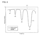
- FIG. 6 is a graph of a relationship between a frequency and a damping constant of each of a working example and a comparative example.
- the damping constant is substantially constant in all of the frequency bands.
- the damping constant decreases in particular frequency bands.
- the interval of the rib members 122 is adjusted so that the specific frequency band of a bending wave subject to damping becomes one of the frequency bands at which the damping constant decreases.
- each of the specific frequency bands A1 to A4 with decreasing damping constants has a frequency width of approximately 50Hz.
- the frequency of a bending wave having a width of approximately 50Hz from the specific frequency corresponding to the interval at which the rib members are disposed is the frequency band which can be reduced.
- FIG. 7 is a detail view of an exemplary configuration of a wind turbine power generating apparatus according to another embodiment of the present invention.
- the wind turbine power generating apparatus 200 includes a rotor 202 which rotates upon receiving wind, a nacelle 205 which rotatably supports a shaft 206 of the rotor 202, a drivetrain 207 for increasing the rotation speed of the rotor shaft 206, a tower 211 of a substantially cylindrical shape supporting the nacelle 205, and a generator 214 which generates electric power.
- the nacelle 205 is yaw rotatable about the tower 211.
- the rotor 202 includes at least one blade 203 and a hub 204 to which the blade 203 is mounted.
- the rotor shaft 206 is mounted to the hub 204 and the rotor 202 is rotated with the rotor shaft 206 by the wind power received at the blade 203. This rotation is inputted into the drivetrain 207 via the rotor shaft 206.
- the hub 204 may be covered by a hub cover 204a.
- the rigidity-enhancing parts are disposed on positions different from those in the above embodiment. That is, as illustrated in FIG. 7 , three rib members 222 are disposed on the inner circumferential surface 211a of the tower 211 as the rigidity-enhancing parts 220 for improving rigidity to reduce the structural borne sound due to oscillatory propagation from the drivetrain 207, in the present embodiment. While the number of the rib members 222 disposed on the inner circumferential surface 211a of the tower 211 is three in the present embodiment illustrated in FIG. 7 , it is sufficient if there are at least two rib members 222, so the number is not limited to three.
- the oscillation frequency "f”, caused during operation of the drivetrain 207, is within the range of from not less than 300Hz to not more than 400Hz.
- the interval of the rib members 222 is set to approximately 1 to 2m.
- the wavelength ⁇ which brings about a reducing effect of oscillatory propagation from the drivetrain 207, is a wavelength which does not have nodes at the rib members 122.
- the interval L of the rib members 222 is adjusted so as to achieve the above effect. In this way, setting the interval L of the rib members 222 on the basis of the oscillation frequency of the drivetrain 207 makes it possible to reduce the oscillatory propagation of a bending wave caused by oscillation of the drivetrain 207 to the tower 211 more precisely.
- the rib members 222 are attached to the inner circumferential surface 211a of the tower 211 at the above interval L, so that the inner circumferential surface 211a is fixed so as not to oscillate at positions where the rib members 222 are disposed. In this way, the structural borne sound due to the oscillatory propagation from the drivetrain 207 to the tower 211 is reduced. As a result, it is possible to reduce the operation noise produced by radiation of structural borne sound from the outer circumferential surface 211b of the tower 211 serving as a radiation plane.
- a flange 224 disposed on an end of the outer circumferential surface 211b of the tower 211 may be employed as one of the rigidity-enhancing parts 220. That is, in addition to attaching the rib members 222 to the inner circumferential surface 211a of the tower 211, the existing flange 224 may be also employed as one of the rigidity-enhancing parts 220 because the flange 224 is also capable of preventing oscillation of the outer circumferential surface 211b of the tower 211.
- the rib members 222 may be disposed on the outer circumferential surface 211b of the tower 211. That is, to reduce the structural borne sound due to oscillatory propagation from the drivetrain 207, it is sufficient if at least two of the rigidity-enhancing parts 220 are disposed on at least one of the inner circumferential surface 211a or the outer circumferential surface 211b of the tower 211.
- the rib members 222 are disposed on the inner circumferential surface 211a of the tower 211, the rib members 222 may be disposed further on at least one of the inner circumferential surface or the outer circumferential surface of the rotor shaft 206. In this way, with the rib members 222 being disposed on at least one of the inner circumferential surface of the outer circumferential surface of the rotor shaft 206 in addition to the tower 211, it is possible to reduce the oscillatory propagation from the drivetrain 207 to the blade 203 and the tower 211. Thus, it is possible to restrict noise due to radiation of structural borne sound from the radiating plane of the blade 203 and the tower 211.
- the present invention is applicable to a gear-less wind turbine power generating apparatus, which does not include a drivetrain. Specifically, in a case where rotation of a rotor shaft is transmitted directly to a generator, oscillatory propagation from the generator is reduced to restrict operation noise.
Landscapes
- Engineering & Computer Science (AREA)
- Life Sciences & Earth Sciences (AREA)
- Sustainable Development (AREA)
- Sustainable Energy (AREA)
- Chemical & Material Sciences (AREA)
- Combustion & Propulsion (AREA)
- Mechanical Engineering (AREA)
- General Engineering & Computer Science (AREA)
- Power Engineering (AREA)
- Wind Motors (AREA)
Abstract
Description
- The present disclosure relates to a wind turbine power generating apparatus.
- Wind turbine power generating apparatuses have become widely used in recent years in view of preservation of the global environment. A wind turbine power generating apparatus includes a tower of a predetermined height and a nacelle disposed on the top of the tower. The nacelle includes a generator and a speed-increasing unit. At least one blade rotated by wind power is mounted to the nacelle, so that the generator is driven by the rotation force of the blade serving as a driving force to generate electric power.
- In a wind turbine power generating apparatus, noise may be produced from oscillation which occurs during operation of a generator or a speed-increasing unit and propagates in the form of waves on the wall surface of a tower, the wall surface serving as an oscillation plate. As a conventional technique for reducing the structural borne sound due to such oscillatory propagation, Patent Document 1 discloses a technique of providing a plurality of blocking masses in a tower. The blocking masses reduce propagation of oscillation which has a frequency corresponding to a property of the blocking masses such as the size, which makes it possible to reduce the operation noise.
- Patent Document 1: Japanese Patent Application Pub. No.
3342148 - Although the blocking masses are effective in reducing propagation of oscillation, the shape of the blocking masses need to be determined so that the rotation shaft is not decentered in a case where the blocking masses are provided for a rotational body.
- In view of the above issues, an object of at least one embodiment of the present invention is to provide a novel and improved wind turbine power generating apparatus capable of reducing structural borne sound due to oscillatory propagation of a particular frequency, with a simplified configuration.
- A wind turbine power generating apparatus according to at least one embodiment of the present invention includes: a nacelle supported on a tower; a rotor which includes a blade for receiving wind power, the rotor being configured to rotate upon receiving wind at the blade; a rotor shaft coupled to the rotor and supported rotatably on the nacelle; a generator which generates electric power from rotational force of the rotor shaft; and at least two rigidity-enhancing parts disposed on an inner circumferential surface or an outer circumferential surface of at least one of the rotor shaft or the tower, at an interval which is set so as to correspond to a frequency of oscillation caused during operation of the generator, or oscillation caused during operation of a drivetrain for transmitting the rotational force of the rotor shaft to the generator in a case where the drivetrain is provided. The at least two rigidity-enhancing parts are arranged in a propagating direction of the oscillation.
- With the above wind turbine power generating apparatus, it is possible to select the frequency of oscillation that is to be reduced in accordance with the interval between the at least two rigidity-enhancing parts. Further, the interval between the rigidity-enhancing parts is set corresponding to the frequency of the oscillation generated during operation of the generator or during operation of the drivetrain. Thus, with the rigidity-enhancing parts, propagation of the bending wave produced by the oscillation generated during operation of the generator or the oscillation of the drivetrain is reduced, which makes it possible to reduce the structural borne sound from the blade or the tower due to propagation of the bending wave.
- In one embodiment of the present invention, when the interval is defined as an interval L and a wavelength of the oscillation caused during the operation of the generator or the drivetrain is defined as λ, the interval L of the rigidity-enhancing parts is set so as to satisfy a following relationship, using an integer "n".

- With the above configuration, it is possible to set the interval of the rigidity-enhancing parts on the basis of the wavelength of the oscillation of the generator or the drivetrain, which makes it possible to reduce the propagation of a bending wave generated by oscillation from the generator or the drivetrain more precisely.
- In one embodiment of the present invention, the rigidity-enhancing parts include at least one of a rib member disposed on the inner circumferential surface or the outer circumferential surface, a bearing of the rotor shaft, or a flange.
- With the above configuration, using one of the rib members, the bearing of the rotor shaft, or the flange makes it possible to reduce the oscillatory propagation of a bending wave generated by oscillation of the generator or the drivetrain with a simplified structure. Especially, if the bearing of the rotor shaft or the flange is used, it is possible to reduce the number of members to be additionally provided, which makes it possible to reduce the oscillatory propagation of a bending wave generated by oscillation of the generator or the drivetrain with a simplified structure.
- In one embodiment of the present invention, the drivetrain includes a hydraulic pump configured to be driven by rotation of the rotor shaft, and a hydraulic motor configured to be driven by pressurized oil generated in the hydraulic pump and to enable the generator to generate electric power.
- With the above configuration, it is possible to reduce the oscillatory propagation of the bending wave even if the bending wave is generated by oscillation of the hydraulic pump or the hydraulic drive.
- As described above, according to at least one embodiment of the prevent invention, provided is a novel and improved wind turbine power generating apparatus capable of reducing the structural borne sound due to oscillatory propagation of a specific frequency with a simplified structure.
-
-
FIG. 1 is a diagram of an overall configuration of a wind turbine power generating apparatus according to one embodiment of the present invention. -
FIG. 2 is a detail view of an exemplary configuration of the wind turbine power generating apparatus according to one embodiment of the present invention. -
FIG. 3 is a diagram of an exemplary configuration of rigidity-enhancing parts of the wind turbine power generating apparatus according to one embodiment of the present invention. -
FIG. 4 is an illustration of an example of a bending wave in a case where the rigidity-enhancing parts are at nodes of the wave. -
FIG. 5 is an illustration of an example of a bending wave in a case where the rigidity-enhancing parts are at anti-nodes of the wave. -
FIG. 6 is a graph of a relationship between a frequency and a damping constant of each of a working example and a comparative example. -
FIG. 7 is a detail view of an exemplary configuration of a wind turbine power generating apparatus according to another embodiment of the present invention. - Embodiments of the present invention will now be described in detail with reference to the accompanying drawings. It is intended, however, that unless particularly specified, dimensions, materials, shapes, relative positions and the like of components described in the embodiments shall be interpreted as illustrative only and not limitative of the scope of the present invention.
- First, the configuration of the wind turbine power generating apparatus according to one embodiment of the present invention will be described with reference to the drawings.
FIG. 1 is a diagram of an overall configuration of a wind turbine power generating apparatus according to one embodiment of the present invention.FIG. 2 is a detail view of an exemplary configuration of the wind turbine power generating apparatus according to one embodiment of the present invention. - In one embodiment, the wind turbine
power generating apparatus 100 includes arotor 102 which rotates upon receiving wind, anacelle 105 which rotatably supports arotor shaft 106 of therotor 102, adrivetrain 107 for increasing the rotation speed of therotor shaft 106, atower 111 of a substantially cylindrical shape supporting thenacelle 105, and agenerator 114 which generates electric power. Thenacelle 105 is capable of yaw rotating about thetower 111. - The
rotor 102 includes at least oneblade 103 and ahub 104 to which theblade 103 is mounted. Therotor shaft 106 is mounted to thehub 104, and therotor 102 is rotated with therotor shaft 106 by the wind power received at theblade 103. This rotation is inputted into thedrivetrain 107 via therotor shaft 106. Thehub 104 may be covered by ahub cover 104a. - The
drivetrain 107 is a speed-increasing unit for increasing the rotation speed of therotor shaft 106 and inputting the rotation to thegenerator 114. In one embodiment, thedrivetrain 107 includes ahydraulic pump 110 coupled to therotor shaft 106, ahydraulic motor 112 coupled to thegenerator 114, and oil circulation lines disposed between thehydraulic pump 110 and thehydraulic motor 112. The circulation lines include a highpressure oil line 116 and a lowpressure oil line 118. The highpressure oil line 116 connects an outlet side of thehydraulic pump 110 and an inlet side of thehydraulic motor 112, while the lowpressure oil line 118 connects an inlet side of thehydraulic pump 110 and an outlet side of thehydraulic motor 112. - The
hydraulic pump 110 is driven by therotor shaft 106 to generate high pressure working oil. The high pressure working oil is supplied to thehydraulic motor 112 through the highpressure oil line 116, and then drives thehydraulic motor 112. At this time, thegenerator 114 coupled to thehydraulic motor 112 is driven to generate electric power. The working oil having been discharged from thehydraulic motor 112 is supplied to thehydraulic pump 110 through the lowpressure oil line 118, has its pressure increased in thehydraulic pump 110, and then returns to thehydraulic motor 112. - In one embodiment, the
drivetrain 107 is a hydraulic transmission described above, though the drivetrain may be a gearbox including planetary gears or the like. In recent years, however, the wind turbinepower generating apparatus 100 has increased in size. Thus, a hydraulic transmission is more preferable as thedrivetrain 107 being a speed-increasing mechanism, because more weight can be reduced in a hydraulic transmission than in a gearbox. - The
rotor shaft 106 is a hollow member of a substantially cylindrical shape including rigid metal material such as iron. In one embodiment, therotor shaft 106 includes, as illustrated inFIG. 2 , tworib members 122 serving as rigidity-enhancingparts 120 for improving rigidity of therotor shaft 106, on the innercircumferential surface 106a of therotor shaft 106. The number of therib members 122 is at least two, and therib members 122 are arranged at an interval which is set corresponding to the frequency of oscillation caused during operation of thehydraulic pump 110 of thedrivetrain 107, in the propagating direction of the oscillation. - As described above, since the
rib members 122 are mounted to the innercircumferential surface 106a of therotor shaft 106, the innercircumferential surface 106a is fixed so as not to oscillate at positions where therib members 122 are disposed. As a result, it is possible to reduce the structural borne sound due to the oscillatory propagation from thehydraulic pump 110. - While two
rib members 122 are disposed on the innercircumferential surface 106a of therotor shaft 106 in the embodiment illustrated inFIG. 2 , it is sufficient if the number of therib members 122 is at least two. Thus, three ormore rib members 122 may be provided. - Further, besides the
rib members 122 disposed on the innercircumferential surface 106a of therotor shaft 106, aflange 126 disposed on an end of the outercircumferential surface 106b of therotor shaft 106 or abearing 124 for supporting therotor shaft 106 rotatably may be employed as the rigidity-enhancingparts 120. That is, in addition to attaching therib members 122 to therotor shaft 106, the existingbearing 124 andflange 126 may be also employed as the rigidity-enhancingparts 120 because thebearing 124 and theflange 126 are also capable of preventing oscillation of the outercircumferential surface 106b of therotor shaft 106. As described above, utilizing thebearing 124 and theflange 126 of therotor shaft 106 makes it possible to reduce the number of members to be additionally attached, and to reduce oscillatory propagation of a bending wave caused by oscillation of thedrivetrain 107 with more simplified configuration. - Further, the
rib members 122 may be disposed on the outercircumferential surface 106b of therotor shaft 106. That is, to reduce the structural borne sound due to oscillatory propagation from thedrivetrain 107, it is sufficient if there are at least tworib members 122 being the rigidity-enhancingparts 120 disposed on at least one of the innercircumferential surface 106a or the outercircumferential surface 106b of therotor shaft 106. - Next, the configuration of the rigidity-enhancing parts included in the wind turbine power generating apparatus according to one embodiment of the present invention will be described in reference to the drawings.
FIG. 3 is a diagram of an exemplary configuration of rigidity-enhancing parts of the wind turbine power generating apparatus according to one embodiment of the present invention. - The oscillation of structural borne sound is mainly caused by a bending wave. Thus, it is effective to reduce propagation of a bending wave in order to reduce structural borne sound. In view of this, in one embodiment, as described in
FIG. 3 ,rib members 122 of an annular shape are additionally disposed on the innercircumferential surface 106a of therotor shaft 106 being a hollow cylindrical member at a predetermined interval L to reduce oscillatory propagation of a bending wave with a specific frequency. Therib members 122 include a rigid material such as metal. The attachment structure of therib members 122 may include an attachment structure in which an annular member is inserted into therotor shaft 106, an attachment structure in which a plate member is bended and inserted into therotor shaft 106, or an attachment structure in which welding is overlaid at positions where therib members 122 are to be disposed. - When the
rib members 122 are attached to the innercircumferential surface 106a of therotor shaft 106 at the predetermined interval L, the innercircumferential surface 106a is fixed so as not to oscillate at positions where therib members 122 are disposed. As described above, when therib members 122 are disposed, a bending wave W1 of oscillation having a node P1 at one of therib members 122 passes through as illustrated inFIG. 4 , while a bending wave W2 of oscillation having an antinode, not a node, at one of therib members 122, is blocked, as illustrated inFIG. 5 . - The oscillation frequencies (excitation frequencies) of the
drivetrain 107 include a number of frequencies, and each of the excitation frequencies has a bending wave that tries to propagate through therotor shaft 106. However, since therib members 122 constitute the support part or the fixation part of therotor shaft 106, a bending wave having nodes at therib members 122 easily propagates on therotor shaft 106, while a wave having no node at therib members 122 has larger damping, which makes it possible to reduce oscillation. - The above frequency to be reduced is determined from the interval of the
rib members 122. Thus, in one embodiment, the interval L of therib members 122 being the rigidity-enhancingparts 120 is determined from a specific frequency of a bending wave whose oscillatory propagation is desired to be reduced, and accordingly, therib members 122 are additionally provided. When the interval between therib members 122 is defined as L, and the wavelength of oscillation caused during operation of thehydraulic pump 110 of thedrivetrain 107 is defined as λ, the interval L of therib members 122 is set so as to satisfy the following relationship, using an integer "n".
- The main source of oscillation of the
drivetrain 107 is thehydraulic pump 110, and the oscillation frequency caused during operation of thehydraulic pump 110 is within the range of from not less than 300Hz to not more than 400Hz. Thus, to reduce oscillatory propagation of a bending wave of an oscillation frequency band within the above range to therotor shaft 106, the interval of therib members 122 is determined to be a value of approximately 1 to 2m from the above relationship. In particular, at this time, the wavelength λ, which brings about a reducing effect of oscillatory propagation from thedrivetrain 107, is a wavelength which does not have nodes at therib members 122. Thus, the interval L of therib members 122 is adjusted so as to achieve the above effect. In this way, setting the interval L of therib members 122 on the basis of the oscillation frequency of thehydraulic pump 110 being the source of oscillation of thedrivetrain 107 makes it possible to reduce the oscillatory propagation of a bending wave caused by oscillation of thedrivetrain 107 to therotor shaft 106 more precisely. - In a conventional wind turbine power generating apparatus, large oscillation occurs in a drivetrain such as a gearbox and a hydraulic drive, and propagates to blades to produce operation noise due to radiation of structural borne sound from the large radiating surface of the blade. Oscillation due to a drivetrain in particular is one of the generation sources of the operation noise, because oscillation of a gearbox, a hydraulic drive or the like transmits to each part of the blade or the like by propagating on a rotor shaft, a rotor head, or the like.
- In view of this, in one embodiment, to reduce the above operation noise, the
rib members 122 are attached to the innercircumferential surface 106a of therotor shaft 106 at the above interval L, and in the propagating direction of the oscillation, so that the innercircumferential surface 106 is fixed at positions where therib members 122 are disposed, so as not to oscillate due to oscillatory propagation from thedrivetrain 107. In this way, providing therib members 122 reduces the structural borne sound due to the oscillatory propagation from thedrivetrain 107 to therotor shaft 106. As a result, it is possible to reduce the operation noise produced via therotor shaft 106 by radiating structural borne sound from theblade 103 serving as a radiation plane. - The
drivetrain 107 such as a gearbox and a hydraulic pump produces oscillation at a specific frequency. Thus, it is unnecessary to reduce oscillation over the entire range of the frequencies. Thus, in one embodiment, a technique is employed such that therib members 122 being the rigidity-enhancingparts 120 are disposed on therotor shaft 106 at the above described specific interval to reduce the oscillation level of a specific frequency, which enables tuning of a specific frequency. - As described above, in one embodiment, the
rib members 122 are disposed on therotor shaft 106 to reduce the oscillation level of a specific frequency due to oscillation, which is to be reduced, from thedrivetrain 107.FIG. 6 is a graph of a relationship between a frequency and a damping constant of each of a working example and a comparative example. - As illustrated in
FIG. 6 , in the comparative example C1 where the rib members are not provided, the damping constant is substantially constant in all of the frequency bands. In contrast, in the working example E1 where the rib members are provided, the damping constant decreases in particular frequency bands. Thus, in one embodiment, the interval of therib members 122 is adjusted so that the specific frequency band of a bending wave subject to damping becomes one of the frequency bands at which the damping constant decreases. As a result, the oscillatory propagation caused by thedrivetrain 107 is reduced. Further, in one embodiment, each of the specific frequency bands A1 to A4 with decreasing damping constants has a frequency width of approximately 50Hz. Thus, the frequency of a bending wave having a width of approximately 50Hz from the specific frequency corresponding to the interval at which the rib members are disposed, is the frequency band which can be reduced. - Next, another embodiment of the present invention will be described with reference to the drawings.
FIG. 7 is a detail view of an exemplary configuration of a wind turbine power generating apparatus according to another embodiment of the present invention. - In the present embodiment, the wind turbine
power generating apparatus 200 includes arotor 202 which rotates upon receiving wind, anacelle 205 which rotatably supports ashaft 206 of therotor 202, adrivetrain 207 for increasing the rotation speed of therotor shaft 206, atower 211 of a substantially cylindrical shape supporting thenacelle 205, and agenerator 214 which generates electric power. Thenacelle 205 is yaw rotatable about thetower 211. - The
rotor 202 includes at least oneblade 203 and ahub 204 to which theblade 203 is mounted. Therotor shaft 206 is mounted to thehub 204 and therotor 202 is rotated with therotor shaft 206 by the wind power received at theblade 203. This rotation is inputted into thedrivetrain 207 via therotor shaft 206. Thehub 204 may be covered by ahub cover 204a. - In the present embodiment, the rigidity-enhancing parts are disposed on positions different from those in the above embodiment. That is, as illustrated in
FIG. 7 , threerib members 222 are disposed on the innercircumferential surface 211a of thetower 211 as the rigidity-enhancingparts 220 for improving rigidity to reduce the structural borne sound due to oscillatory propagation from thedrivetrain 207, in the present embodiment. While the number of therib members 222 disposed on the innercircumferential surface 211a of thetower 211 is three in the present embodiment illustrated inFIG. 7 , it is sufficient if there are at least tworib members 222, so the number is not limited to three. - When the interval between the
rib members 222 is defined as L, and the wavelength of oscillation caused during operation of thedrivetrain 207 is defined as λ, the interval L of therib members 122 is set so as to satisfy the following relationship, using an integer "n".
- The oscillation frequency "f", caused during operation of the
drivetrain 207, is within the range of from not less than 300Hz to not more than 400Hz. Thus, the interval of therib members 222 is set to approximately 1 to 2m. In particular, at this time, the wavelength λ, which brings about a reducing effect of oscillatory propagation from thedrivetrain 207, is a wavelength which does not have nodes at therib members 122. Thus, the interval L of therib members 222 is adjusted so as to achieve the above effect. In this way, setting the interval L of therib members 222 on the basis of the oscillation frequency of thedrivetrain 207 makes it possible to reduce the oscillatory propagation of a bending wave caused by oscillation of thedrivetrain 207 to thetower 211 more precisely. - As described above, the
rib members 222 are attached to the innercircumferential surface 211a of thetower 211 at the above interval L, so that the innercircumferential surface 211a is fixed so as not to oscillate at positions where therib members 222 are disposed. In this way, the structural borne sound due to the oscillatory propagation from thedrivetrain 207 to thetower 211 is reduced. As a result, it is possible to reduce the operation noise produced by radiation of structural borne sound from the outercircumferential surface 211b of thetower 211 serving as a radiation plane. - Besides the
rib members 222 disposed on the innercircumferential surface 211a of thetower 211, aflange 224 disposed on an end of the outercircumferential surface 211b of thetower 211 may be employed as one of the rigidity-enhancingparts 220. That is, in addition to attaching therib members 222 to the innercircumferential surface 211a of thetower 211, the existingflange 224 may be also employed as one of the rigidity-enhancingparts 220 because theflange 224 is also capable of preventing oscillation of the outercircumferential surface 211b of thetower 211. - Further, the
rib members 222 may be disposed on the outercircumferential surface 211b of thetower 211. That is, to reduce the structural borne sound due to oscillatory propagation from thedrivetrain 207, it is sufficient if at least two of the rigidity-enhancingparts 220 are disposed on at least one of the innercircumferential surface 211a or the outercircumferential surface 211b of thetower 211. - Further, while the
rib members 222 are disposed on the innercircumferential surface 211a of thetower 211, therib members 222 may be disposed further on at least one of the inner circumferential surface or the outer circumferential surface of therotor shaft 206. In this way, with therib members 222 being disposed on at least one of the inner circumferential surface of the outer circumferential surface of therotor shaft 206 in addition to thetower 211, it is possible to reduce the oscillatory propagation from thedrivetrain 207 to theblade 203 and thetower 211. Thus, it is possible to restrict noise due to radiation of structural borne sound from the radiating plane of theblade 203 and thetower 211. - Each embodiment of the present invention were described in detail above, but the present invention is not limited thereto, as it will be understood easily by those skilled in the art, and various amendments and modifications may be implemented within a scope that does not depart from the present invention.
- For instance, a term which has been described at least once in the specification or the drawings, associated with another term having a broader or similar meaning, may be substituted by this other term anywhere in the specification and the drawings. Further, the configuration and operation of the wind turbine power generating apparatus are not limited to those described in each embodiment of the present invention, and a wide range of variations can be adopted.
- Further, while the drivetrain increases the rotation speed of the rotor shaft and transmits the rotational force to the generator in the wind turbine power generating apparatus of each above embodiment, the present invention is applicable to a gear-less wind turbine power generating apparatus, which does not include a drivetrain. Specifically, in a case where rotation of a rotor shaft is transmitted directly to a generator, oscillatory propagation from the generator is reduced to restrict operation noise.
-
- 100
- Wind turbine power generating apparatus
- 102
- Rotor
- 103
- Blade
- 104
- Hub
- 106
- Rotor shaft
- 106a
- Inner circumferential surface
- 106b
- Outer circumferential surface
- 110
- Hydraulic pump
- 112
- Hydraulic motor
- 114
- Generator
- 116
- High pressure oil line
- 118
- Low pressure oil line
- 120
- Rigidity-enhancing part
- 122
- Rib member
- 124
- Bearing
- 126
- Flange
Claims (4)
- A wind turbine power generating apparatus, comprising:a nacelle supported on a tower;a rotor which includes a blade for receiving wind power, the rotor being configured to rotate upon receiving wind at the blade;a rotor shaft coupled to the rotor and supported rotatably on the nacelle;a generator which generates electric power from rotational force of the rotor shaft; andat least two rigidity-enhancing parts disposed on an inner circumferential surface or an outer circumferential surface of at least one of the rotor shaft or the tower, at an interval which is set so as to correspond to a frequency of oscillation caused during operation of the generator, or oscillation caused during operation of a drivetrain for transmitting the rotational force of the rotor shaft to the generator in a case where the drivetrain is provided, the at least two rigidity-enhancing parts being arranged in a propagating direction of the oscillation.
- The wind turbine power generating apparatus according to claim 1,
wherein, when the interval is defined as an interval L and a wavelength of the oscillation caused during the operation of the generator or the drivetrain is defined as λ, the interval L of the rigidity-enhancing parts is set so as to satisfy a following relationship, using an integer "n".
- The wind turbine power generating apparatus according to claim 2,
wherein the rigidity-enhancing parts include at least one of a rib member disposed on the inner circumferential surface or the outer circumferential surface, a bearing of the rotor shaft, or a flange. - The wind turbine power generating apparatus according to any one of claims 1 to 3,
wherein the drivetrain includes a hydraulic pump configured to be driven by rotation of the rotor shaft, and a hydraulic motor configured to be driven by pressurized oil generated in the hydraulic pump and to enable the generator to generate electric power.
Applications Claiming Priority (1)
| Application Number | Priority Date | Filing Date | Title |
|---|---|---|---|
| PCT/JP2013/053504 WO2014125593A1 (en) | 2013-02-14 | 2013-02-14 | Wind turbine generator |
Publications (3)
| Publication Number | Publication Date |
|---|---|
| EP2896828A1 true EP2896828A1 (en) | 2015-07-22 |
| EP2896828A4 EP2896828A4 (en) | 2015-10-14 |
| EP2896828B1 EP2896828B1 (en) | 2016-11-16 |
Family
ID=51353626
Family Applications (1)
| Application Number | Title | Priority Date | Filing Date |
|---|---|---|---|
| EP13875197.9A Not-in-force EP2896828B1 (en) | 2013-02-14 | 2013-02-14 | Wind turbine generator |
Country Status (3)
| Country | Link |
|---|---|
| EP (1) | EP2896828B1 (en) |
| JP (1) | JP6017012B2 (en) |
| WO (1) | WO2014125593A1 (en) |
Cited By (1)
| Publication number | Priority date | Publication date | Assignee | Title |
|---|---|---|---|---|
| CN109072872A (en) * | 2016-02-24 | 2018-12-21 | 维斯塔斯风力系统集团公司 | Suppression of Wind Turbine Oscillations |
Families Citing this family (4)
| Publication number | Priority date | Publication date | Assignee | Title |
|---|---|---|---|---|
| CN106567803A (en) * | 2016-10-28 | 2017-04-19 | 同济大学 | Round pipe liquid damper used for weakening edge vibration of wind turbine blades |
| JP6251794B1 (en) * | 2016-11-04 | 2017-12-20 | 三菱重工業株式会社 | Renewable energy type power generation apparatus and assembly method thereof |
| CN109441731A (en) * | 2019-01-14 | 2019-03-08 | 重庆大学 | A kind of wind-powered electricity generation pure steel structure tower having double mechanism of putting more energy into-carry |
| KR102296201B1 (en) * | 2020-11-10 | 2021-09-01 | 한전케이피에스 주식회사 | Design method for rib and installation method for same |
Family Cites Families (13)
| Publication number | Priority date | Publication date | Assignee | Title |
|---|---|---|---|---|
| JP3342148B2 (en) | 1994-01-12 | 2002-11-05 | 三菱重工業株式会社 | Anti-vibration device for cylindrical structures |
| DE19930751A1 (en) * | 1999-07-02 | 2001-01-04 | Franz Mitsch | Process for reducing vibrations in wind turbines |
| EP1533521A1 (en) * | 2003-11-21 | 2005-05-25 | General Electric Company | Wind power plant with reduced noise emission |
| JPWO2005095794A1 (en) * | 2004-03-31 | 2008-07-31 | 株式会社アイ・ピー・ビー | Cantilever vertical axis wind turbine |
| JP2006046107A (en) * | 2004-08-02 | 2006-02-16 | Yanmar Co Ltd | Wind power generator |
| JP2006046227A (en) * | 2004-08-06 | 2006-02-16 | Hitachi Engineering & Services Co Ltd | Vertical shaft pinwheel |
| US20060277843A1 (en) * | 2005-05-13 | 2006-12-14 | Tracy Livingston | Structural tower |
| JP2007040146A (en) * | 2005-08-02 | 2007-02-15 | Ishikawajima Harima Heavy Ind Co Ltd | Wind power generator |
| US7931438B2 (en) * | 2006-12-13 | 2011-04-26 | General Electric Company | Active tower damper |
| DK2238347T3 (en) * | 2007-12-21 | 2018-10-29 | Vestas Wind Sys As | A WINDMILL, A PROCEDURE FOR REDUCING NOISE MISSION FROM A WINDMILL TOWER AND USING A WINDMILL |
| US8074450B2 (en) * | 2008-08-13 | 2011-12-13 | General Electric Company | Wind energy system with fluid-working machine with non-symmetric actuation |
| JP2010150985A (en) * | 2008-12-24 | 2010-07-08 | Mitsubishi Heavy Ind Ltd | Cylindrical structure and wind power generator |
| EP2454475B1 (en) * | 2010-05-28 | 2015-10-28 | Mitsubishi Heavy Industries, Ltd. | Power generating apparatus of renewable energy type and method of operating the same |
-
2013
- 2013-02-14 JP JP2015500040A patent/JP6017012B2/en not_active Expired - Fee Related
- 2013-02-14 WO PCT/JP2013/053504 patent/WO2014125593A1/en not_active Ceased
- 2013-02-14 EP EP13875197.9A patent/EP2896828B1/en not_active Not-in-force
Cited By (2)
| Publication number | Priority date | Publication date | Assignee | Title |
|---|---|---|---|---|
| CN109072872A (en) * | 2016-02-24 | 2018-12-21 | 维斯塔斯风力系统集团公司 | Suppression of Wind Turbine Oscillations |
| US10982651B2 (en) | 2016-02-24 | 2021-04-20 | Vestas Wind Systems A/S | Damping of a wind turbine tower oscillation |
Also Published As
| Publication number | Publication date |
|---|---|
| JPWO2014125593A1 (en) | 2017-02-02 |
| EP2896828A4 (en) | 2015-10-14 |
| EP2896828B1 (en) | 2016-11-16 |
| JP6017012B2 (en) | 2016-10-26 |
| WO2014125593A1 (en) | 2014-08-21 |
Similar Documents
| Publication | Publication Date | Title |
|---|---|---|
| EP2896828B1 (en) | Wind turbine generator | |
| RU2634841C2 (en) | Aircraft configured to hang | |
| EP2275705A1 (en) | Transmission unit and wind power generator | |
| NZ529356A (en) | Cooling device for a wind turbine generator | |
| US9125394B2 (en) | Ultrasonic sound emitting devices for wind turbines | |
| US20130164135A1 (en) | Active Noise Suppression on a Wind Turbine | |
| US10018186B2 (en) | Wind turbines and methods | |
| EP3211218B1 (en) | Acoustic damping system for a wind turbine tower | |
| JPH1193670A (en) | Fan shroud | |
| US20140021722A1 (en) | Dual Rotor Wind or Water Turbine | |
| KR20110068445A (en) | Turbine Generator and Wave Power Generation System Using the Same | |
| CN106849832A (en) | The method for noise reduction control and device of electric machine control system and its frequency converter | |
| EP2784306A1 (en) | Cooling device for a wind turbine generator | |
| JP2002303254A (en) | Wind power generator | |
| JP2010150985A (en) | Cylindrical structure and wind power generator | |
| CN104455345B (en) | Micro-perforated web face gear noise reduction structure and noise reduction structure parameter designing method thereof | |
| EP2843229A1 (en) | Wind power generation system | |
| EP2524866A3 (en) | A variable pitch propeller rotor | |
| KR20140064305A (en) | Turbine generator with torque measurement function and wave generation system using thereof | |
| WO2015044425A2 (en) | A sound emitter | |
| EP3587804A1 (en) | Wind turbine power generation facility and maintenance method therefore | |
| JP6145055B2 (en) | Wind turbine tower and wind power generator | |
| KR101566501B1 (en) | Downwind Windpower Generating Apparatus having Swept Blade Tip | |
| CN208153252U (en) | Blower denoising structure and wind-driven generator | |
| KR102208470B1 (en) | Wind power generator |
Legal Events
| Date | Code | Title | Description |
|---|---|---|---|
| PUAI | Public reference made under article 153(3) epc to a published international application that has entered the european phase |
Free format text: ORIGINAL CODE: 0009012 |
|
| 17P | Request for examination filed |
Effective date: 20150330 |
|
| AK | Designated contracting states |
Kind code of ref document: A1 Designated state(s): AL AT BE BG CH CY CZ DE DK EE ES FI FR GB GR HR HU IE IS IT LI LT LU LV MC MK MT NL NO PL PT RO RS SE SI SK SM TR |
|
| AX | Request for extension of the european patent |
Extension state: BA ME |
|
| RA4 | Supplementary search report drawn up and despatched (corrected) |
Effective date: 20150910 |
|
| RIC1 | Information provided on ipc code assigned before grant |
Ipc: F03D 11/04 20060101ALI20150904BHEP Ipc: F03D 11/02 20060101AFI20150904BHEP |
|
| DAX | Request for extension of the european patent (deleted) | ||
| REG | Reference to a national code |
Ref country code: DE Ref legal event code: R079 Ref document number: 602013014277 Country of ref document: DE Free format text: PREVIOUS MAIN CLASS: F03D0011020000 Ipc: F03D0015000000 |
|
| GRAP | Despatch of communication of intention to grant a patent |
Free format text: ORIGINAL CODE: EPIDOSNIGR1 |
|
| RIC1 | Information provided on ipc code assigned before grant |
Ipc: F03D 15/00 20160101AFI20160531BHEP Ipc: F03D 13/20 20160101ALI20160531BHEP |
|
| INTG | Intention to grant announced |
Effective date: 20160621 |
|
| GRAS | Grant fee paid |
Free format text: ORIGINAL CODE: EPIDOSNIGR3 |
|
| GRAA | (expected) grant |
Free format text: ORIGINAL CODE: 0009210 |
|
| AK | Designated contracting states |
Kind code of ref document: B1 Designated state(s): AL AT BE BG CH CY CZ DE DK EE ES FI FR GB GR HR HU IE IS IT LI LT LU LV MC MK MT NL NO PL PT RO RS SE SI SK SM TR |
|
| REG | Reference to a national code |
Ref country code: GB Ref legal event code: FG4D |
|
| REG | Reference to a national code |
Ref country code: CH Ref legal event code: EP |
|
| REG | Reference to a national code |
Ref country code: IE Ref legal event code: FG4D |
|
| REG | Reference to a national code |
Ref country code: AT Ref legal event code: REF Ref document number: 846212 Country of ref document: AT Kind code of ref document: T Effective date: 20161215 |
|
| REG | Reference to a national code |
Ref country code: DE Ref legal event code: R096 Ref document number: 602013014277 Country of ref document: DE |
|
| REG | Reference to a national code |
Ref country code: FR Ref legal event code: PLFP Year of fee payment: 5 |
|
| PG25 | Lapsed in a contracting state [announced via postgrant information from national office to epo] |
Ref country code: LV Free format text: LAPSE BECAUSE OF FAILURE TO SUBMIT A TRANSLATION OF THE DESCRIPTION OR TO PAY THE FEE WITHIN THE PRESCRIBED TIME-LIMIT Effective date: 20161116 |
|
| REG | Reference to a national code |
Ref country code: NL Ref legal event code: MP Effective date: 20161116 |
|
| REG | Reference to a national code |
Ref country code: LT Ref legal event code: MG4D |
|
| REG | Reference to a national code |
Ref country code: AT Ref legal event code: MK05 Ref document number: 846212 Country of ref document: AT Kind code of ref document: T Effective date: 20161116 |
|
| PG25 | Lapsed in a contracting state [announced via postgrant information from national office to epo] |
Ref country code: LT Free format text: LAPSE BECAUSE OF FAILURE TO SUBMIT A TRANSLATION OF THE DESCRIPTION OR TO PAY THE FEE WITHIN THE PRESCRIBED TIME-LIMIT Effective date: 20161116 Ref country code: NO Free format text: LAPSE BECAUSE OF FAILURE TO SUBMIT A TRANSLATION OF THE DESCRIPTION OR TO PAY THE FEE WITHIN THE PRESCRIBED TIME-LIMIT Effective date: 20170216 Ref country code: NL Free format text: LAPSE BECAUSE OF FAILURE TO SUBMIT A TRANSLATION OF THE DESCRIPTION OR TO PAY THE FEE WITHIN THE PRESCRIBED TIME-LIMIT Effective date: 20161116 Ref country code: GR Free format text: LAPSE BECAUSE OF FAILURE TO SUBMIT A TRANSLATION OF THE DESCRIPTION OR TO PAY THE FEE WITHIN THE PRESCRIBED TIME-LIMIT Effective date: 20170217 Ref country code: SE Free format text: LAPSE BECAUSE OF FAILURE TO SUBMIT A TRANSLATION OF THE DESCRIPTION OR TO PAY THE FEE WITHIN THE PRESCRIBED TIME-LIMIT Effective date: 20161116 |
|
| PG25 | Lapsed in a contracting state [announced via postgrant information from national office to epo] |
Ref country code: ES Free format text: LAPSE BECAUSE OF FAILURE TO SUBMIT A TRANSLATION OF THE DESCRIPTION OR TO PAY THE FEE WITHIN THE PRESCRIBED TIME-LIMIT Effective date: 20161116 Ref country code: PL Free format text: LAPSE BECAUSE OF FAILURE TO SUBMIT A TRANSLATION OF THE DESCRIPTION OR TO PAY THE FEE WITHIN THE PRESCRIBED TIME-LIMIT Effective date: 20161116 Ref country code: AT Free format text: LAPSE BECAUSE OF FAILURE TO SUBMIT A TRANSLATION OF THE DESCRIPTION OR TO PAY THE FEE WITHIN THE PRESCRIBED TIME-LIMIT Effective date: 20161116 Ref country code: HR Free format text: LAPSE BECAUSE OF FAILURE TO SUBMIT A TRANSLATION OF THE DESCRIPTION OR TO PAY THE FEE WITHIN THE PRESCRIBED TIME-LIMIT Effective date: 20161116 Ref country code: PT Free format text: LAPSE BECAUSE OF FAILURE TO SUBMIT A TRANSLATION OF THE DESCRIPTION OR TO PAY THE FEE WITHIN THE PRESCRIBED TIME-LIMIT Effective date: 20170316 Ref country code: FI Free format text: LAPSE BECAUSE OF FAILURE TO SUBMIT A TRANSLATION OF THE DESCRIPTION OR TO PAY THE FEE WITHIN THE PRESCRIBED TIME-LIMIT Effective date: 20161116 Ref country code: RS Free format text: LAPSE BECAUSE OF FAILURE TO SUBMIT A TRANSLATION OF THE DESCRIPTION OR TO PAY THE FEE WITHIN THE PRESCRIBED TIME-LIMIT Effective date: 20161116 Ref country code: BE Free format text: LAPSE BECAUSE OF NON-PAYMENT OF DUE FEES Effective date: 20170228 |
|
| PG25 | Lapsed in a contracting state [announced via postgrant information from national office to epo] |
Ref country code: DK Free format text: LAPSE BECAUSE OF FAILURE TO SUBMIT A TRANSLATION OF THE DESCRIPTION OR TO PAY THE FEE WITHIN THE PRESCRIBED TIME-LIMIT Effective date: 20161116 Ref country code: SK Free format text: LAPSE BECAUSE OF FAILURE TO SUBMIT A TRANSLATION OF THE DESCRIPTION OR TO PAY THE FEE WITHIN THE PRESCRIBED TIME-LIMIT Effective date: 20161116 Ref country code: EE Free format text: LAPSE BECAUSE OF FAILURE TO SUBMIT A TRANSLATION OF THE DESCRIPTION OR TO PAY THE FEE WITHIN THE PRESCRIBED TIME-LIMIT Effective date: 20161116 Ref country code: RO Free format text: LAPSE BECAUSE OF FAILURE TO SUBMIT A TRANSLATION OF THE DESCRIPTION OR TO PAY THE FEE WITHIN THE PRESCRIBED TIME-LIMIT Effective date: 20161116 Ref country code: CZ Free format text: LAPSE BECAUSE OF FAILURE TO SUBMIT A TRANSLATION OF THE DESCRIPTION OR TO PAY THE FEE WITHIN THE PRESCRIBED TIME-LIMIT Effective date: 20161116 |
|
| REG | Reference to a national code |
Ref country code: DE Ref legal event code: R097 Ref document number: 602013014277 Country of ref document: DE |
|
| PG25 | Lapsed in a contracting state [announced via postgrant information from national office to epo] |
Ref country code: SM Free format text: LAPSE BECAUSE OF FAILURE TO SUBMIT A TRANSLATION OF THE DESCRIPTION OR TO PAY THE FEE WITHIN THE PRESCRIBED TIME-LIMIT Effective date: 20161116 Ref country code: IT Free format text: LAPSE BECAUSE OF FAILURE TO SUBMIT A TRANSLATION OF THE DESCRIPTION OR TO PAY THE FEE WITHIN THE PRESCRIBED TIME-LIMIT Effective date: 20161116 Ref country code: BE Free format text: LAPSE BECAUSE OF FAILURE TO SUBMIT A TRANSLATION OF THE DESCRIPTION OR TO PAY THE FEE WITHIN THE PRESCRIBED TIME-LIMIT Effective date: 20161116 Ref country code: BG Free format text: LAPSE BECAUSE OF FAILURE TO SUBMIT A TRANSLATION OF THE DESCRIPTION OR TO PAY THE FEE WITHIN THE PRESCRIBED TIME-LIMIT Effective date: 20170216 |
|
| PLBE | No opposition filed within time limit |
Free format text: ORIGINAL CODE: 0009261 |
|
| STAA | Information on the status of an ep patent application or granted ep patent |
Free format text: STATUS: NO OPPOSITION FILED WITHIN TIME LIMIT |
|
| PG25 | Lapsed in a contracting state [announced via postgrant information from national office to epo] |
Ref country code: MC Free format text: LAPSE BECAUSE OF FAILURE TO SUBMIT A TRANSLATION OF THE DESCRIPTION OR TO PAY THE FEE WITHIN THE PRESCRIBED TIME-LIMIT Effective date: 20161116 |
|
| REG | Reference to a national code |
Ref country code: CH Ref legal event code: PL |
|
| 26N | No opposition filed |
Effective date: 20170817 |
|
| PG25 | Lapsed in a contracting state [announced via postgrant information from national office to epo] |
Ref country code: LI Free format text: LAPSE BECAUSE OF NON-PAYMENT OF DUE FEES Effective date: 20170228 Ref country code: CH Free format text: LAPSE BECAUSE OF NON-PAYMENT OF DUE FEES Effective date: 20170228 |
|
| REG | Reference to a national code |
Ref country code: IE Ref legal event code: MM4A |
|
| PG25 | Lapsed in a contracting state [announced via postgrant information from national office to epo] |
Ref country code: SI Free format text: LAPSE BECAUSE OF FAILURE TO SUBMIT A TRANSLATION OF THE DESCRIPTION OR TO PAY THE FEE WITHIN THE PRESCRIBED TIME-LIMIT Effective date: 20161116 |
|
| PG25 | Lapsed in a contracting state [announced via postgrant information from national office to epo] |
Ref country code: LU Free format text: LAPSE BECAUSE OF NON-PAYMENT OF DUE FEES Effective date: 20170214 |
|
| REG | Reference to a national code |
Ref country code: FR Ref legal event code: PLFP Year of fee payment: 6 |
|
| PG25 | Lapsed in a contracting state [announced via postgrant information from national office to epo] |
Ref country code: IE Free format text: LAPSE BECAUSE OF NON-PAYMENT OF DUE FEES Effective date: 20170214 |
|
| PG25 | Lapsed in a contracting state [announced via postgrant information from national office to epo] |
Ref country code: MT Free format text: LAPSE BECAUSE OF NON-PAYMENT OF DUE FEES Effective date: 20170214 |
|
| PG25 | Lapsed in a contracting state [announced via postgrant information from national office to epo] |
Ref country code: HU Free format text: LAPSE BECAUSE OF FAILURE TO SUBMIT A TRANSLATION OF THE DESCRIPTION OR TO PAY THE FEE WITHIN THE PRESCRIBED TIME-LIMIT; INVALID AB INITIO Effective date: 20130214 |
|
| PG25 | Lapsed in a contracting state [announced via postgrant information from national office to epo] |
Ref country code: CY Free format text: LAPSE BECAUSE OF FAILURE TO SUBMIT A TRANSLATION OF THE DESCRIPTION OR TO PAY THE FEE WITHIN THE PRESCRIBED TIME-LIMIT Effective date: 20161116 |
|
| PG25 | Lapsed in a contracting state [announced via postgrant information from national office to epo] |
Ref country code: MK Free format text: LAPSE BECAUSE OF FAILURE TO SUBMIT A TRANSLATION OF THE DESCRIPTION OR TO PAY THE FEE WITHIN THE PRESCRIBED TIME-LIMIT Effective date: 20161116 |
|
| PG25 | Lapsed in a contracting state [announced via postgrant information from national office to epo] |
Ref country code: TR Free format text: LAPSE BECAUSE OF FAILURE TO SUBMIT A TRANSLATION OF THE DESCRIPTION OR TO PAY THE FEE WITHIN THE PRESCRIBED TIME-LIMIT Effective date: 20161116 |
|
| PG25 | Lapsed in a contracting state [announced via postgrant information from national office to epo] |
Ref country code: AL Free format text: LAPSE BECAUSE OF FAILURE TO SUBMIT A TRANSLATION OF THE DESCRIPTION OR TO PAY THE FEE WITHIN THE PRESCRIBED TIME-LIMIT Effective date: 20161116 Ref country code: IS Free format text: LAPSE BECAUSE OF FAILURE TO SUBMIT A TRANSLATION OF THE DESCRIPTION OR TO PAY THE FEE WITHIN THE PRESCRIBED TIME-LIMIT Effective date: 20170316 |
|
| PGFP | Annual fee paid to national office [announced via postgrant information from national office to epo] |
Ref country code: FR Payment date: 20210113 Year of fee payment: 9 |
|
| PGFP | Annual fee paid to national office [announced via postgrant information from national office to epo] |
Ref country code: GB Payment date: 20210203 Year of fee payment: 9 |
|
| PGFP | Annual fee paid to national office [announced via postgrant information from national office to epo] |
Ref country code: DE Payment date: 20211230 Year of fee payment: 10 |
|
| GBPC | Gb: european patent ceased through non-payment of renewal fee |
Effective date: 20220214 |
|
| PG25 | Lapsed in a contracting state [announced via postgrant information from national office to epo] |
Ref country code: FR Free format text: LAPSE BECAUSE OF NON-PAYMENT OF DUE FEES Effective date: 20220228 |
|
| PG25 | Lapsed in a contracting state [announced via postgrant information from national office to epo] |
Ref country code: GB Free format text: LAPSE BECAUSE OF NON-PAYMENT OF DUE FEES Effective date: 20220214 |
|
| REG | Reference to a national code |
Ref country code: DE Ref legal event code: R082 Ref document number: 602013014277 Country of ref document: DE Representative=s name: CBDL PATENTANWAELTE GBR, DE |
|
| REG | Reference to a national code |
Ref country code: DE Ref legal event code: R119 Ref document number: 602013014277 Country of ref document: DE |
|
| PG25 | Lapsed in a contracting state [announced via postgrant information from national office to epo] |
Ref country code: DE Free format text: LAPSE BECAUSE OF NON-PAYMENT OF DUE FEES Effective date: 20230901 |