EP2896565A1 - Track fitting assembly having a visible indicator to confirm engagement with a track - Google Patents
Track fitting assembly having a visible indicator to confirm engagement with a track Download PDFInfo
- Publication number
- EP2896565A1 EP2896565A1 EP15150275.4A EP15150275A EP2896565A1 EP 2896565 A1 EP2896565 A1 EP 2896565A1 EP 15150275 A EP15150275 A EP 15150275A EP 2896565 A1 EP2896565 A1 EP 2896565A1
- Authority
- EP
- European Patent Office
- Prior art keywords
- track fitting
- cam
- track
- button
- aperture
- Prior art date
- Legal status (The legal status is an assumption and is not a legal conclusion. Google has not performed a legal analysis and makes no representation as to the accuracy of the status listed.)
- Granted
Links
Images





Classifications
-
- B—PERFORMING OPERATIONS; TRANSPORTING
- B64—AIRCRAFT; AVIATION; COSMONAUTICS
- B64D—EQUIPMENT FOR FITTING IN OR TO AIRCRAFT; FLIGHT SUITS; PARACHUTES; ARRANGEMENT OR MOUNTING OF POWER PLANTS OR PROPULSION TRANSMISSIONS IN AIRCRAFT
- B64D11/00—Passenger or crew accommodation; Flight-deck installations not otherwise provided for
- B64D11/06—Arrangements of seats, or adaptations or details specially adapted for aircraft seats
- B64D11/0696—Means for fastening seats to floors, e.g. to floor rails
-
- B—PERFORMING OPERATIONS; TRANSPORTING
- B60—VEHICLES IN GENERAL
- B60P—VEHICLES ADAPTED FOR LOAD TRANSPORTATION OR TO TRANSPORT, TO CARRY, OR TO COMPRISE SPECIAL LOADS OR OBJECTS
- B60P7/00—Securing or covering of load on vehicles
- B60P7/06—Securing of load
- B60P7/08—Securing to the vehicle floor or sides
- B60P7/0807—Attachment points
- B60P7/0815—Attachment rails or trellis
-
- Y—GENERAL TAGGING OF NEW TECHNOLOGICAL DEVELOPMENTS; GENERAL TAGGING OF CROSS-SECTIONAL TECHNOLOGIES SPANNING OVER SEVERAL SECTIONS OF THE IPC; TECHNICAL SUBJECTS COVERED BY FORMER USPC CROSS-REFERENCE ART COLLECTIONS [XRACs] AND DIGESTS
- Y10—TECHNICAL SUBJECTS COVERED BY FORMER USPC
- Y10T—TECHNICAL SUBJECTS COVERED BY FORMER US CLASSIFICATION
- Y10T403/00—Joints and connections
- Y10T403/20—Joints and connections with indicator or inspection means
Definitions
- the disclosed system and method relate to a track fitting assembly and, more particularly, to systems and methods for providing a visible indicator to confirm that the track fitting assembly is in an engaged position within a track.
- each edge 36 of the track 30 may include a series of generally semi-circular recesses 46 and a series of raised sections 50.
- FIG. 1 illustrates semi-circular recesses 46, it is to be understood that the recesses 46 may include other profiles as well.
- the recesses 46 located along one of the edges 36 of the track 30 may cooperate with the recesses 46 located along an opposing edge 36 of the track 30 to define a series of holes 42 within the longitudinal slot 40.
- recess 46a located along one of the edges 36 of the track 30 cooperates with an opposing recess 46b located on the other edge 36 of the track 30 to define a hole 42a.
- FIG. 10 is an alternative embodiment of a track fitting assembly 310.
- the track fitting assembly 310 may include a lower track fitting 322, a biasing member 323, a button 324, an upper track fitting 326, and a cam 328. Similar to the embodiment as described above and shown in FIGS. 1-9 , the track fitting assembly 310 may also be used for securing a structure (not shown) to the track 30 (shown in FIG. 1 ).
- the lower track fitting 322 may include a bottom section 350 and a upper section 352. The bottom section 350 of the lower track fitting 322 may be selectively received by the longitudinal slot 40 in the track 30 (shown in FIG. 1 ).
- the cam 328 may include an outer perimeter 432, an upper surface 444, a lower surface 446, a main body 450, a key recess 452, a pinion portion 464, and an aperture 466.
- the key recess 452 may extend through the upper surface 444 of the main body 450 of the cam 328, but not through the lower surface 446 of the main body 450 of the cam 328.
- the key aperture 152 may include a hexagonal profile, which may be configured to engage with a hex key (not shown).
- the upper track fitting 326 may include an upper surface 420, a lower surface 422, two sliding surfaces 424, two generally opposing flanges 426, and a main body 428.
- the main body 428 may define a generally circular aperture 430, which may correspond with the outer perimeter 432 of the cam 328.
- the aperture 430 located in the main body 428 of the upper track fitting 236 may receive the cam 328.
- the cam 328 may be selectively rotatable within the aperture 430 of the upper track fitting 326.
- the two flanges 426 may each include a corresponding bolt hole 433.
- the bolt holes 433 may be used to secure a structure (not shown) to the track fitting assembly 310.
- the button 324 may be received by the aperture 466 of the cam 328. Moreover, the lower track fitting 322 may be moved by an incremental distance I' in the first direction relative to the upper track fitting 326 and the track 30 (the track 30 is shown in FIGS. 1 , 3 , 4-5 and 7 ). Additionally, the indicator surface 470 located inside of the aperture 466 (shown in FIGS. 10-12 ) may no longer be visible when the track fitting assembly 310 is in the engaged position. Instead, the indicator surface 400 of the button 324 may now be visible to a user. Similar to the embodiment as shown in FIGS.
Landscapes
- Engineering & Computer Science (AREA)
- Aviation & Aerospace Engineering (AREA)
- Mechanical Engineering (AREA)
- Transportation (AREA)
- Seats For Vehicles (AREA)
- General Engineering & Computer Science (AREA)
- Connection Of Plates (AREA)
Abstract
Description
- The disclosed system and method relate to a track fitting assembly and, more particularly, to systems and methods for providing a visible indicator to confirm that the track fitting assembly is in an engaged position within a track.
- A passenger aircraft may include seat tracks that extend along a floor of a cabin. The seat tracks may be used in combination with seat track fittings to affix passenger seats to the floor of the cabin. In addition to passenger seats much larger structures, which are referred to as monuments, may also be affixed to the floor of the cabin as well. Some examples of monuments include, but are not limited to, a partition, a closet, a lavatory, or a galley.
- Several approaches currently exist for installing the monument to the seat track. These approaches typically require a first individual to install the seat track fitting to the seat track and a second individual, who may be referred to as a witness, to confirm the installation was performed correctly. For example, in one approach to install the monument, the seat track fittings are first engaged with locating features in the seat track. The seat track fittings are then taped into place along the seat track by the first individual. The witness then confirms that the seat track fittings are correctly installed to the seat track. Once installation is confirmed by the witness, the monument may be secured to the seat track fittings.
- In another approach to install the monument, one or more bolts and the seat track fittings are first loosely installed to the monument. The monument is then positioned in place along the seat tracks by the first individual, where a set of locating features of the seat track fitting are disengaged from the seat track. Positioning the monument in place along the seat track may be challenging, as there is typically very limited space between the seat track and the monument. The monument may then be slid along the seat track in either the forward or aft direction, which engages the locating features with the seat track. The witness may then tighten the bolts, thereby installing the monument to the seat track.
- Both of these approaches for installing the monument to the seat track have drawbacks. For example, the first individual has to wait for the witness to arrive and confirm that the seat track fittings are correctly installed before the monument may be secured to the seat track. Moreover, it may be difficult to view the seat track fittings clearly within the seat track, especially if the monument has already been installed.
- In one embodiment, a track fitting assembly is provided having an engaged position and an unengaged position. The track fitting assembly may include a lower track fitting, a cam member, a button, and a biasing member. The lower track fitting may define a recess therein and at least one retaining feature. The retaining feature may be configured to hold the lower track fitting within a track if the track fitting assembly is in the engaged position. The cam member may have a cam main body that defines an aperture. The button may have an indicator surface. The button may be selectively retained within the recess of the lower track fitting. The biasing member may be configured to exert a biasing force. The biasing member may be retained within the recess of the lower track fitting and positioned relative to the button to exert the biasing force against the button. The biasing force may urge the button through the aperture of the cam member such that the indicator surface of the button is visible through the aperture of the cam member if the track fitting assembly is in the engaged position.
- In another embodiment, a method of actuating a track fitting assembly from an unengaged position to an engaged position may include positioning a lower track fitting within a longitudinal slot of a track. The lower track fitting may define a recess and at least one retaining feature configured to hold the lower track fitting within the track. The method may also include rotating a cam member by a predetermined amount, where the cam member may include an aperture. The method may also include exerting a biasing force on a button by a biasing member. The biasing member may be retained within the recess of the lower track fitting and may be positioned relative to the button to exert the biasing force against the button. The method may also include urging the button through the aperture in the cam member by the biasing force if the track fitting assembly is in the engaged position. The button includes an indicator surface that may be visible through the aperture of the cam member.
- Other objects and advantages of the disclosed method and system will be apparent from the following description, the accompanying drawings and the appended claims.
-
-
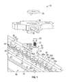
FIG. 1 is an exploded perspective view of an embodiment of the disclosed track fitting assembly and a track; -
FIG. 2 is a bottom perspective view of a lower track fitting and an upper track fitting shown inFIG. 1 ; -
FIG. 3 is an exploded view of the track fitting assembly and the track shown inFIG. 1 ; -
FIG. 4 is an elevated perspective view of the track fitting assembly and the track shown inFIG. 1 in a first, unengaged position; -
FIG. 5 is an elevated perspective view of the track fitting assembly and the track shown inFIG. 1 in a second, engaged position; -
FIG. 6 is an elevated perspective view of a portion of the upper track fitting shown inFIG. 1 ; -
FIG. 7 is an elevated perspective view of a portion of the track fitting assembly shown inFIG. 1 in the unengaged position; -
FIG. 8 is an elevated perspective view of the entire track fitting assembly shown inFIG. 1 in the unengaged position; -
FIG. 9 is an elevated perspective view of the entire track fitting assembly shown inFIG. 1 in the engaged position; -
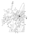
FIG. 10 is an exploded view of an alternative embodiment of the track fitting assembly shown inFIG. 1 ; -
FIG. 11 is a bottom view of a cam shown inFIG. 10 ; -
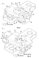
FIG. 12 is an elevated perspective view of the track fitting assembly shown inFIG. 10 in the unengaged position; -
FIG. 13 is an elevated perspective view of the track fitting assembly shown inFIG. 10 in the second, engaged position; and -
FIG. 14 is an exemplary process flow digram illustrating a method of actuating the disclosed track fitting assemblies from the unengaged position to the engaged position. - As shown in
FIG. 1 , the disclosed track fitting assembly, generally designated 10, may comprise a lower track fitting 22, abiasing member 23, abutton 24, an upper track fitting 26, and acam 28. Thetrack fitting assembly 10 may be used for securing a structure (not shown) to atrack 30. In one embodiment, the structure may be any type of device fixedly attached to a floor of an aircraft such as, for example, a passenger seat or a monument. The monument may be any compartmental structure such as, for example, a closet, a lavatory, or a galley. Thetrack 30 may extend along a floor of a cabin of a passenger aircraft (not shown). Although an aircraft is described, it is to be understood that thetrack fitting assembly 10 and thetrack 30 may be used in any other application where adjustable rails may be employed as well such as, for example, buses, boats, and shipping cargo bays. Thetrack 30 may include an upper portion 32 and alower portion 34. The upper portion 32 of thetrack 30 may include twoopposing edges 36 and anupper surface 38. The twoopposing edges 36 of thetrack 30 may define alongitudinal slot 40 for selectively retaining the lower track fitting 22 of thetrack fitting assembly 10. - In the exemplary embodiment as shown in
FIG. 1 , eachedge 36 of thetrack 30 may include a series of generallysemi-circular recesses 46 and a series of raisedsections 50. AlthoughFIG. 1 illustratessemi-circular recesses 46, it is to be understood that therecesses 46 may include other profiles as well. Therecesses 46 located along one of theedges 36 of thetrack 30 may cooperate with therecesses 46 located along an opposingedge 36 of thetrack 30 to define a series ofholes 42 within thelongitudinal slot 40. For example,recess 46a located along one of theedges 36 of thetrack 30 cooperates with an opposingrecess 46b located on theother edge 36 of thetrack 30 to define ahole 42a. Similarly, the raisedsections 50 located along one of theedges 36 of thetrack 30 may cooperate with the raisedsections 50 located on the opposingedge 36 of thetrack 30 to define a series oflands 44 within thelongitudinal slot 40. For example, raisedsection 50a located along one of theedges 36 of thetrack 30 cooperates with an opposing raisedsection 50b located on theother edge 36 of thetrack 30 to define aland 44a. - Referring to both
FIGS. 1-2 , the lower track fitting 22 may include abottom section 51 and aupper section 52. Thebottom section 51 of the lower track fitting 22 may be selectively received by thelongitudinal slot 40 in the track 30 (shown inFIG. 1 ). Theupper section 52 of the lower track fitting 22 may be slidingly engaged with a correspondinglongitudinal slot 56 located within the upper track fitting 26. Thebottom section 51 of the lower track fitting 22 may include at least one lobed orhead portion 60 and at least oneneck portion 62. In the exemplary embodiment as shown inFIGS. 1-2 , the lower track fitting 22 includes twohead portions 60 and aneck portion 62 located between the twohead portions 60. In one embodiment, thehead portions 60 of the lower track fitting 22 may include a generally circular or rounded profile P1 (shown inFIG. 2 ) that corresponds with a profile P2 of theholes 42 located within thelongitudinal slot 40 of thetrack 30. Thus, thehead portions 60 of the lower track fitting 22 may pass through theholes 42 in thelongitudinal slot 40 of thetrack 30. Similarly, theneck portions 62 of the lower track fitting 22 may also correspond with thelands 44 located within thelongitudinal slot 40 of thetrack 30. Thus, theneck portions 62 of the lower track fitting 22 may also pass through thelands 44 in thelongitudinal slot 40 of thetrack 30. - Referring to
FIG. 2 , the upper track fitting 26 may also include at least onehead portion 70 and at least oneneck portion 72. In the exemplary embodiment as shown inFIGS. 1-2 , thehead portions 70 of the upper track fitting 26 may also have a generally semi-circular profile that corresponds with theholes 42 located within thelongitudinal slot 40 of thetrack 30. Thus, thehead portions 70 of the upper track fitting 26 may also pass through theholes 42 in thelongitudinal slot 40 of thetrack 30. Similarly, theneck portions 72 of the upper track fitting 26 may also correspond with thelands 44 located within thelongitudinal slot 40 of thetrack 30. Thus, theneck portions 72 of the upper track fitting 26 also may pass through thelands 44 in thelongitudinal slot 40 of thetrack 30. -
FIG. 3 is an exploded view of thetrack fitting assembly 10. In the embodiment as shown, the lower track fitting 22 has been placed within thelongitudinal slot 40 of thetrack 30 in a first, unengaged position. When the lower track fitting 22 is in the unengaged position within thelongitudinal slot 40 of thetrack 30, thehead portions 60 of the lower track fitting 22 may be generally aligned with therecesses 46 located along a correspondingedge 36 of thetrack 30. Similarly, theneck portion 62 of the lower track fitting 22 (seen inFIG. 2 ) may also be generally aligned with the raisedsections 50 located along a correspondingedge 36 of thetrack 30. Thus, if thetrack fitting assembly 10 is positioned in the unengaged position along thelongitudinal slot 40 of thetrack 30, the lower track fitting 22 may pass through or be removed from thetrack 30.FIG. 4 is an illustration of the assembledtrack fitting assembly 10 positioned within thetrack 30 in the unengaged position. -
FIG. 5 is an illustration of thetrack fitting assembly 10 positioned within thetrack 30 in a second, engaged position. A user may actuate thetrack fitting assembly 10 from the unengaged position (FIG. 4 ) to the engaged position by rotating thecam 28 in a clockwise direction C, which is described in greater detail below. Rotation of thecam 28 may cause the lower track fitting 22 to slide within thelongitudinal slot 40 of thetrack 30 and thelongitudinal slot 56 of the upper track fitting 26 in afirst direction 58, and into the engaged position. Specifically, the lower track fitting 22 may slide within thetrack 30 and the upper track fitting 26 by an incremental distance I. The incremental distance I may be measured between a rear end face 48 of thelower track fitting 22 and a rear end face 54 of the upper track fitting 26. The rear end face 48 of thelower track fitting 22 and the rear end face 54 of the upper track fitting 26 may both be oriented in a direction that is generally transverse to thefirst direction 58. - If the
track fitting assembly 10 is in the engaged position, the lower track fitting 22 may not pass through thetrack 30. Referring generally toFIGS. 2-3 and5 , the lower track fitting 22 may not pass through thetrack 30 in the engaged position because thehead portions 60 of the lower track fitting 22 may no longer be generally aligned with therecesses 46 located along a correspondingedge 36 of thetrack 30. Also, theneck portion 62 of the lower track fitting 22 (seen inFIG. 2 ) may no longer be generally aligned with the raisedsections 50 located along a correspondingedge 36 of thetrack 30. Thehead portions 60 of the lower track fitting 22 may not pass through the raisedsections 50 located along theedges 36 of thetrack 30. Thus, thehead portions 60 may be used as retaining features to hold the lower track fitting 22 within thetrack 30 if the track fitting assembly is in the engaged position. - Referring back to
FIG. 3 , theupper section 52 of the lower track fitting 22 may project above theupper surface 38 of thetrack 30. Theupper section 52 of the lower track fitting 22 may include two generally opposingtongues 78. Eachtongue 78 may be located along alongitudinal side 80 of theupper section 52 of thelower track fitting 22. Theslot 56 of the upper track fitting 26 may include two correspondinggroove sections 82, which may each slidingly receive one of the twotongues 78 of the lower track fitting 22 (the sliding engagement is shown inFIG. 2 ). - A
transverse slot 86 and arecess 90 may each be located along anupper surface 92 of thelower track fitting 22. Thetransverse slot 86 may include a length L1 measured in a direction transverse to a longitudinal length L2 of thelower track fitting 22. In one embodiment, therecess 90 may be a generally cylindrical opening sized to receive the biasingmember 23 and thebutton 24. Specifically, the biasingmember 23 may first be placed within therecess 90, and thebutton 24 may then be placed above the biasingmember 23. - Referring to
FIGS. 3 and8 , when thetrack fitting assembly 10 is in the unengaged position, an upper orindicator surface 100 of thebutton 24 may abut against aninner surface 102 of the upper track fitting 26. The biasingmember 23 may exert a spring or biasing force against alower surface 104 of the button 24 (shown inFIG. 3 ). However, the abutment between theindicator surface 100 of thebutton 24 and theinner surface 102 of the upper track fitting 26 retains both the biasingmember 23 and thebutton 24 within therecess 90 of thelower track fitting 22. The biasing force exerted by the biasingmember 23 may be directed in an upwards direction U, towards theinner surface 102 of the upper track fitting 26. The biasingmember 23 is illustrated as a compression spring, however it is to be understood that any type device configured to exert a biasing force against thebutton 24 may be used as well. - Referring to
FIG. 3 , thebutton 24 may include a generally cylindrical body with a first diameter D1, as well as an enlargedbottom end 106. Thebottom end 106 of thebutton 24 may include astep 108, anengagement surface 110, and a second diameter D2. The first diameter D1 of thebutton 24 may be less than the second diameter D2 of thebottom end 106. In one embodiment, theindicator surface 100 of thebutton 24 may include any type of marking or coloration that clearly distinguishes theindicator surface 100 from the remaining surfaces of thetrack fitting assembly 10. For example, in one embodiment the indicator may be paint of any color, or a phosphorescent paint. The indicator may be used to provide a visible indication of whether thetrack fitting assembly 10 is in the engaged position, and is described in greater detail below. - The
cam 28 may also include anindicator surface 170 inside of akey aperture 152 of thecam 28 as well. Similar to theindicator surface 100 of thebutton 24, theindicator surface 170 located inside of thekey aperture 152 may also include any type of marking or coloration that clearly distinguishes theindicator surface 170 from the remaining surfaces of thetrack fitting assembly 10. Theindicator surface 170 may be used to provide a visible indication that thetrack fitting assembly 10 is in the disengaged position. In one non-limiting embodiment, theindicator surface 170 of thekey aperture 152 may be painted red for certification reasons. - The upper track fitting 26 may include an
upper surface 120, alower surface 122, two slidingsurfaces 124, two generally opposingflanges 126, and amain body 128. Themain body 128 may define a generallycircular aperture 130, which corresponds with anouter perimeter 132 of thecam 28. Thus, as seen inFIGS. 5 and8 , theaperture 130 located in themain body 128 of the upper track fitting 26 may receive thecam 28. Thecam 28 may be selectively rotatable within theaperture 130 of the upper track fitting 26. Turning back toFIG. 3 , the twoflanges 126 may each include acorresponding bolt hole 133. The bolt holes 133 may be used to secure a structure (not shown) to thetrack fitting assembly 10. As mentioned above, the structure may be any device such as, for example, a passenger seat or a monument for an aircraft. - Referring to
FIGS. 6 and 7 , the two slidingsurfaces 124 of the upper track fitting 26 may each be located along abottom end 140 of one of thegroove sections 82 within theslot 56. When theupper section 52 of the lower track fitting 22 is slidingly engaged with thelongitudinal slot 56 of the upper track fitting 26 (the engagement is shown inFIGS. 4-5 ), the two slidingsurfaces 124 of the upper track fitting 26 may abut and slide against two slidingsurfaces 134 located along eachtongue 78 of the lower track fitting 22 (shown inFIG. 7 ). In one embodiment, the two slidingsurfaces 124 may include a generally ramped profile. Referring toFIGS. 4-6 , the lower track fitting 22 includes afront end face 47 and therear end face 48, and the upper track fitting 26 includes afront end face 53 and therear end face 54. The two slidingsurfaces 124 of the upper track fitting 26 may each be sloped or ramped in the longitudinal direction. Specifically, the two slidingsurfaces 124 may be ramped between thefront end face 53 and the rear end face 54 of the upper track fitting 26 along a longitudinal axis A-A. For example, in one embodiment the two slidingsurfaces 124 may include a ramp or slope of about five degrees between thefront end face 53 and the rear end face 54 of the upper track fitting 26. - Referring to
FIG. 7 , the two slidingsurfaces 134 located on eachtongue 78 of the lower track fitting 22 may also be ramped in a direction that generally corresponds with the two slidingsurfaces 124 of the upper track fitting 26. Specifically, the two slidingsurfaces 134 may be ramped between thefront end face 47 and the rear end face 48 of the lower track fitting 22 along the longitudinal axis A-A as well. For example, in one embodiment the two slidingsurfaces 134 may include a ramp of about five degrees between thefront end face 47 and the rear end face 48 of thelower track fitting 22. Referring toFIGS. 4-7 , when thetrack fitting assembly 10 is positioned within thelongitudinal slot 40 of thetrack 30 in either the engaged or the disengaged position, the abutment between the slidingsurfaces 124 of the upper track fitting 26 and the two slidingsurfaces 134 of the lower track fitting 22 may create a clamping force between the upper track fitting 26 and thelower track fitting 22. The clamping force may reduce or substantially eliminate rattle between the upper track fitting 26, thelower track fitting 22, and thetrack 30. - Referring back to
FIG. 3 , thecam 28 may include theouter perimeter 132, anupper surface 144, alower surface 146, and amain body 150. Thekey aperture 152 may be centrally located within themain body 150 of thecam 28, and may extend between theupper surface 144 and thelower surface 146 of themain body 150 of thecam 28. In the exemplary embodiment as shown inFIG. 3 , thekey aperture 152 may include a generally hexagonal profile, however it is to be understood that thekey aperture 152 may include other profiles as well. Thekey aperture 152 may be configured to receive and matingly engage with a cross-section of a hex key (not shown). Thus, a user may insert the hex key into thekey aperture 152 to rotate thecam 28 within theaperture 130 of the upper track fitting 26, which is described in greater detail below. Although a hex key is described, it is to be understood that any other key member or tool having a cross-section that generally corresponds with thekey aperture 152 may be used as well. - The
key aperture 152 may also include a hexagonal diameter D3. The hexagonal diameter D3 may be measured between two opposing sides S of thekey aperture 152. The hexagonal diameter D3 may be greater than the first diameter D1 of thebutton 24, but also less than the second diameter D2 of thebottom end 106 of thebutton 24. Thus, a portion of thebutton 24 may protrude through thekey aperture 152 when thetrack fitting assembly 10 is actuated into the second, engaged position (shown inFIGS. 5 and9 ). However, thebottom end 106 of thebutton 24 may not pass through thekey aperture 152. Instead, theengagement surface 110 of thebottom end 106 of thebutton 24 may abut against thelower surface 146 of thecam 28. - Continuing to refer to
FIG. 3 , thelower surface 146 of thecam 28 may include aboss 156 that projects outwardly away from thelower surface 146 of thecam 28. Theboss 156 may be sized to slide back and forth along the length L1 of thetransverse slot 86 of thelower track fitting 22. Turning now toFIG. 7 , an illustration of thetrack fitting assembly 10 placed in the unengaged position within thetrack 30 is shown, where the upper track fitting 26 has been omitted in order to more clearly show theupper surface 92 of thelower track fitting 22. Theboss 156 of thecam 28 may abut against afirst end 160 of the transverse slot 86 (thefirst end 160 is seen inFIG. 3 ) when thetrack fitting assembly 10 is in the unengaged position. - Referring to both
FIGS. 3 and7 , a user may rotate thecam 28 within theaperture 130 of the upper track fitting 26 in the clockwise direction C in order to actuate thetrack fitting assembly 10 from the unengaged position into the engaged position. Specifically, rotation of thecam 28 in the clockwise direction C causes theboss 156 of thecam 28 to travel from thefirst end 160 of thetransverse slot 86 and towards asecond end 162 of thetransverse slot 86, and back towards thefirst end 160 of thetransverse slot 86. The rotation of thecam 28 in the clockwise direction C may also urge the lower track fitting 22 to slide infirst direction 58. - Referring specifically to
FIG. 7 , when thetrack fitting assembly 10 is in the unengaged position, thebutton 24 may be generally aligned with thekey aperture 152 of thecam 28 in the longitudinal direction. Moreover, thebutton 24 may also be positioned at a predetermined longitudinal distance D from thekey aperture 152. Theindicator surface 170 located inside of thekey aperture 152 may be visible to a user. - Turning now to
FIG. 8 , an illustration of the entiretrack fitting assembly 10 is shown in the unengaged position. The upper track fitting 26 has been illustrated inFIG. 8 as a transparent component in order to reveal thetransverse slot 86 located within thelower track fitting 22, as well as thebutton 24 located within therecess 90 of thelower track fitting 22. When thetrack fitting assembly 10 is in the unengaged position, theindicator surface 100 of thebutton 24 may abut against theinner surface 102 of the upper track fitting 26, and may not be visible to a user. - In one embodiment, a user may insert a hex key (not shown) into the
key aperture 152. The user may rotate the hex key in the clockwise direction C, which in turn also rotates thecam 28 in the clockwise direction C. Specifically, a user may rotate thecam 28 within theaperture 130 of the upper track fitting 26 by a predetermined amount, which in turn may actuate thetrack fitting assembly 10 from the unengaged position into the engaged position (shown inFIG. 9 ). In one exemplary embodiment, the predetermined amount of rotation of thecam 28 may be about ninety degrees. - Referring to both
FIGS. 3 and8 , thecam 28 may rotate in the clockwise direction C while theboss 156 of thecam 28 travels twice the length L1 of thetransverse slot 86 of thelower track fitting 22. Specifically, the boss of thecam 28 may first travel from thefirst end 160 towards thesecond end 162 of thetransverse slot 86, and back towards thefirst end 160 of thetransverse slot 86. Theboss 156 of thecam 28 may then abut against thefirst end 160 of thetransverse slot 86 in thelower track fitting 22. The abutment between theboss 156 of thecam 28 and thefirst end 160 of thetransverse slot 86 in the lower track fitting 22 may prevent further rotation of thecam 28 in the clockwise direction. Moreover, thetrack fitting assembly 10 may be in the engaged position as shown inFIG. 9 once theboss 156 of thecam 28 abuts against thefirst end 160 of thetransverse slot 86 in thelower track fitting 22. -
FIG. 9 is an illustration of thetrack fitting assembly 10 in the engaged position, where the upper track fitting has been illustrated as a transparent component. Thebutton 24 may be received by thekey aperture 152 of thecam 28. The engagement of thebutton 24 within thekey aperture 152 of thecam 28 may lock thetrack fitting assembly 10 in the engaged position. When thetrack fitting assembly 10 is in the engaged position, the lower track fitting 22 has been moved by the incremental distance I in thefirst direction 58 relative to the upper track fitting 26 and the track 30 (thetrack 30 is shown inFIGS. 1 ,3 ,4-5 and7 ). Also, when thetrack fitting assembly 10 is in the engaged position theindicator surface 170 located inside of the key aperture 152 (shown inFIGS. 7-8 ) may no longer be visible. Instead, theindicator surface 100 of thebutton 24 may now be visible to a user, and provides an indication that thetrack fitting assembly 10 is in the engaged position. - Referring to both
FIGS. 3 and9 , when thetrack fitting assembly 10 is in the engaged position at least a portion of thebutton 24 may no longer be retained within therecess 90 of thelower track fitting 22. Instead, the biasingmember 23 may exert the biasing force against thelower surface 104 of thebutton 24 to urge at least a portion of thebutton 24 out of therecess 90 of thelower track fitting 22, and through thekey aperture 152 of thecam 28 such that theindicator surface 100 is visible to a user. In one embodiment, theindicator surface 100 of thebutton 24 may be flush or generally aligned with theupper surface 144 of thecam 28. Theengagement surface 110 of thebottom end 106 of the button 24 (FIG. 3 ) may abut against thelower surface 146 of thecam 28. The engagement between thebottom end 106 of thebutton 24 and thelower surface 146 of thecam 28 may retain thebutton 24 within thekey aperture 152 of thecam 28. Thus, the biasing force exerted by the biasingmember 23 may not urge thebutton 24 out of thekey aperture 152 of thecam 28. - In order to actuate the
track fitting assembly 10 back into the unengaged position (shown inFIG. 8 ), a user may place the hex key (not shown) back into thekey aperture 152 of thecam 28. The hex key may urge or push thebutton 24 downwardly, and back into therecess 90 located along theupper surface 92 of the lower track fitting 22 (shown inFIG. 3 ). A user may then rotate the hex key and thecam 28 in the counterclockwise direction CC. Rotation of thecam 28 in the counterclockwise direction CC may cause the lower track fitting 22 to slide within thelongitudinal slot 40 of the track 30 (FIG. 1 ) and thelongitudinal slot 56 of the upper track fitting 26 in asecond direction 59. Thesecond direction 59 generally opposes thefirst direction 58. -
FIG. 10 is an alternative embodiment of a trackfitting assembly 310. The trackfitting assembly 310 may include alower track fitting 322, a biasingmember 323, abutton 324, an upper track fitting 326, and acam 328. Similar to the embodiment as described above and shown inFIGS. 1-9 , the trackfitting assembly 310 may also be used for securing a structure (not shown) to the track 30 (shown inFIG. 1 ). The lower track fitting 322 may include abottom section 350 and aupper section 352. Thebottom section 350 of the lower track fitting 322 may be selectively received by thelongitudinal slot 40 in the track 30 (shown inFIG. 1 ). Theupper section 352 of the lower track fitting 322 may be slidingly engaged with a correspondinglongitudinal slot 356 located within the upper track fitting 326. Thebottom section 350 of the lower track fitting 322 may include at least onehead portion 360 and at least oneneck portion 362. The upper track fitting 326 may also include at least onehead portion 370 and at least oneneck portion 372. - The lower track fitting 322 may also include two
tongues 378. Eachtongue 378 may be located along alongitudinal side 380 of theupper section 352 of thelower track fitting 322. Theslot 356 located within the upper track fitting 326 may include two correspondinggroove sections 382, which each slidingly receive one of the twotongues 378 of thelower track fitting 322. The sliding engagement between the twogroove sections 382 of the upper track fitting 326 and the twotongues 378 of the lower track fitting 322 is shown inFIG. 12 . - Referring to
FIG. 10 , theupper section 352 of the lower track fitting 322 may include anupper surface 392 and arack 348. Therack 348 may be located along one of thelongitudinal sides 380 of theupper section 352 of thelower track fitting 322. Therack 348 may extend along at least a portion of a longitudinal length L2' of thelower track fitting 322. In the exemplary embodiment as shown inFIG. 10 , therack 348 extends along the entire longitudinal length L2' of thelower track fitting 322. Therack 348 may include a series ofteeth 354. Theteeth 354 may be configured to meshingly engage with a set of correspondingteeth 458 located on thecam 328. - The
cam 328 may include anouter perimeter 432, anupper surface 444, alower surface 446, amain body 450, akey recess 452, apinion portion 464, and anaperture 466. Thekey recess 452 may extend through theupper surface 444 of themain body 450 of thecam 328, but not through thelower surface 446 of themain body 450 of thecam 328. In the exemplary embodiment as shown inFIG. 10 , thekey aperture 152 may include a hexagonal profile, which may be configured to engage with a hex key (not shown). Theaperture 466 of thecam 328 may be located along theouter perimeter 432 of thecam 328, and may extend through both theupper surface 444 and thelower surface 446 of themain body 450 of thecam 328. Theaperture 466 of thecam 328 may be sized to selectively receive thebutton 324. Referring toFIG. 11 , thepinion portion 464 of thecam 328 may be located along thelower surface 446 of thecam 328. Thepinion portion 464 may be generally cylindrical in shape, and theteeth 458 may be located around anouter circumference 468 of thepinion portion 464. - Referring back to
FIG. 10 , arecess 390 may be disposed along theupper surface 392 of thelower track fitting 322. Specifically, therecess 390 may be positioned along one of thelongitudinal sides 380 of theupper section 352 of thelower track fitting 322. In the embodiment as shown, therecess 390 may be positioned along the longitudinal side of theupper section 352 of the lower track fitting 322 that does not include therack 348. In one embodiment, therecess 390 may be a generally cylindrical opening sized to receive the biasingmember 323 and thebutton 324. The biasingmember 323 may first be placed within therecess 390, and thebutton 324 may then be placed above the biasingmember 323. -
FIG. 12 is an illustration of the trackfitting assembly 310 in the unengaged position. Thebutton 324 may be generally aligned with theaperture 466 of thecam 328 in the longitudinal direction, where thebutton 324 may be positioned at a longitudinal distance D' from theaperture 466. Referring to bothFIGS. 10 and12 , when the trackfitting assembly 310 is in the unengaged position, anindicator surface 400 of thebutton 324 may abut against aninner surface 402 of the upper track fitting 326. The biasingmember 323 may exert a biasing force against alower surface 404 of the button 324 (shown inFIG. 10 ). However, the abutment between theindicator surface 400 of thebutton 324 and theinner surface 402 of the upper track fitting 326 retains both the biasingmember 323 and thebutton 324 within therecess 390 of thelower track fitting 322. - Similar to the embodiment as described above and shown in
FIGS. 1-9 , theindicator surface 400 of thebutton 324 may include any type of marking or coloration that clearly distinguishes theindicator surface 400 of thebutton 324 from the remaining portions of the trackfitting assembly 310. It should be noted that thebutton 324 may include an enlarged bottom end, similar to thebottom end 106 of thebutton 24 shown inFIG. 3 . Moreover, similar to the embodiment as shown inFIGS. 1-9 , thecam 328 may also include anindicator surface 470 inside of therecess 466 as well. Theindicator surface 470 may also include any type of marking or coloration that clearly distinguishes theindicator surface 470 from the remaining surfaces of the trackfitting assembly 310. - Referring to both
FIGS. 10 and12 , the upper track fitting 326 may include anupper surface 420, alower surface 422, two slidingsurfaces 424, two generally opposingflanges 426, and amain body 428. Themain body 428 may define a generallycircular aperture 430, which may correspond with theouter perimeter 432 of thecam 328. Thus, as seen inFIG. 12 , theaperture 430 located in themain body 428 of the upper track fitting 236 may receive thecam 328. Thecam 328 may be selectively rotatable within theaperture 430 of the upper track fitting 326. The twoflanges 426 may each include acorresponding bolt hole 433. The bolt holes 433 may be used to secure a structure (not shown) to the trackfitting assembly 310. Similar to the embodiment as shown inFIGS. 1-9 , the two slidingsurfaces 424 of the upper track fitting 326 and two slidingsurfaces 434 of the lower track fitting 322 may both include a generally ramped profile. Specifically, the two slidingsurfaces 434 of the lower track fitting 322 may be ramped in a direction that generally corresponds with the two slidingsurfaces 424 of the upper track fitting 326, and has been described in detail above and illustrated inFIG. 6 . - Referring to
FIGS. 11 and 12 , theteeth 354 located on therack 348 of the lower track fitting 322 may meshingly engage with theteeth 458 located on thepinion portion 464 of the cam 328 (shown inFIG. 11 ), which creates a rack and pinion type engagement between thelower track fitting 322 and thecam 328. Thus, as a user rotates thecam 328 within theaperture 430 of the upper track fitting 326 in the clockwise direction C, the rack and pinion type engagement between thelower track fitting 322 and thecam 328 may translate the rotational motion of thecam 328 into linear motion of thelower track fitting 322. Specifically, the rotation of thecam 328 in the clockwise direction C may be translated into linear motion of the lower track fitting 322 in afirst direction 258. Similarly, rotation of thecam 328 in the counterclockwise direction CC may be translated into linear motion of the lower track fitting 322 in asecond direction 259. - Similar to the embodiment as described above and shown in
FIGS. 1-9 , a user may insert a hex key (not shown) into thekey recess 452 of thecam 328. The user may rotate the hex key in the clockwise direction C by the predetermined amount, which in turn rotates thecam 328 in the clockwise direction C by the predetermined amount within theaperture 430 of the upper track fitting 326, and into the engaged position (shown inFIG. 13 ). In the exemplary embodiment as shown inFIGS. 10-13 , the predetermined amount of rotation of thecam 328 may be about three hundred and sixty degrees. - Turning now to
FIG. 13 , when the trackfitting assembly 310 is in the engaged position thebutton 324 may be received by theaperture 466 of thecam 328. Moreover, the lower track fitting 322 may be moved by an incremental distance I' in the first direction relative to the upper track fitting 326 and the track 30 (thetrack 30 is shown inFIGS. 1 ,3 ,4-5 and7 ). Additionally, theindicator surface 470 located inside of the aperture 466 (shown inFIGS. 10-12 ) may no longer be visible when the trackfitting assembly 310 is in the engaged position. Instead, theindicator surface 400 of thebutton 324 may now be visible to a user. Similar to the embodiment as shown inFIGS. 1-9 , a hex key (not shown) may be placed into thekey recess 452 of thecam 328 in order to actuate thetrack fitting assembly 10 back into the unengaged position. At the same time thebutton 324 may be urged or pushed downwardly, and back into therecess 390 located along theupper surface 392 of the lower track fitting 322 (shown inFIG. 10 ). A user may then rotate the hex key and thecam 328 in a counterclockwise direction CC. -
FIG. 14 is a process flow diagram illustrating anexemplary method 500 for actuating either thetrack fitting assembly 10 as shown inFIGS. 1-9 or the trackfitting assembly 310 as shown inFIGS. 10-13 from the unengaged position to the engaged position. Referring generally toFIGS. 1-14 ,method 500 may begin atblock 502, where thetrack fitting assembly longitudinal slot 40 of thetrack 30 in the unengaged position.Method 500 may then proceed to block 504. - In
block 504, a user may place a hex key (not illustrated) in thekey aperture 152 of the cam 28 (FIGS. 1-9 ), or thekey recess 452 of the cam 328 (FIGS. 10-13 ).Method 500 may then proceed to block 506. - In
block 506, thecam FIGS. 1-9 , the predetermined amount of rotation may be about ninety degrees. In the embodiment as shown inFIGS. 10-13 , the predetermined amount of rotation may be about three hundred and sixty degrees.Method 500 may then proceed to block 508. - In
block 508, a user may perform a visual inspection to confirm that thetrack fitting assembly FIGS. 1-9 , when thetrack fitting assembly 10 is in the engaged position, theindicator surface 100 of thebutton 24 may be viewed through thekey aperture 152 of thecam 28. Similarly, in the embodiments as shown inFIGS. 10-13 , when the trackfitting assembly 310 is in the engaged position, theindicator surface 400 of thebutton 324 may be viewed through theaperture 466 of thecam 328.Method 500 may then terminate. - Referring generally to
FIGS. 1-14 , in one embodiment a user may actuate the disclosed track fitting assembly 10 (illustrated inFIGS. 1-9 ) from the unengaged position to the engaged position using only one hand, which may make thetrack fitting assembly 10 especially attractive in some types applications. In contrast, the trackfitting assembly 310 may be beneficial in applications where a driving mechanism with enhanced robustness is needed (i.e., the rack and pinion type engagement between thelower track fitting 322 and the cam 328). - Both of the disclosed track
fitting assemblies track 30 when compared to some types of track fitting assemblies available today. This is because some other track fitting assemblies currently available may require two individuals to install the monument to the track. Specifically, a first individual may install the track fitting to the track and a second individual, who may be referred to as a witness, confirms the installation was performed correctly. However, the first individual has to wait for the witness to arrive and confirm that the track fittings are correctly installed before the monument may be secured to the track. In contrast, the disclosed trackfitting assemblies track 30. - Additionally, it may also be challenging to position the monument in place and engage the track fittings with the track using the mechanisms that are currently available. There is typically very limited space between the track and the monument, and it may be difficult to view the track fittings to confirm engagement with the track. However, the disclosed track
fitting assemblies fitting assemblies indicator surface button - While the forms of apparatus and methods herein described constitute preferred embodiments of this disclosure, it is to be understood that the disclosure is not limited to these precise forms of apparatus and methods, and the changes may be made therein without departing from the scope of the disclosure.
Claims (15)
- A track fitting assembly (10) having an engaged position and an unengaged position, comprising:a lower track fitting (22) defining a recess therein and at least one retaining feature (60), wherein the at least one retaining feature is configured to hold the lower track fitting within a track (30) if the track fitting assembly is in the engaged position;a cam (28) member having a cam main body that defines an aperture (152);a button (24) having an indicator surface (100), wherein the button is selectively retained within the recess of the lower track fitting; anda biasing (23) member configured to exert a biasing force, wherein the biasing member is retained within the recess of the lower track fitting and positioned relative to the button to exert the biasing force against the button, and wherein the biasing force urges the button through the aperture of the cam member such that the indicator surface (100) of the button is visible through the aperture of the cam member if the track fitting assembly is in the engaged position.
- The track fitting assembly (10) of claim 1, wherein the button (24) is retained within the recess (46) of the lower track fitting (22) and is not visible if the track fitting assembly is in the unengaged position.
- The track fitting assembly (10) of any preceding claim, further comprising an upper track fitting (26) having a longitudinal slot (56), wherein the lower track fitting (22) is slidingly engaged with the longitudinal slot of the upper track fitting (26) and optionally:i) wherein the upper track fitting includes a main body (128) that defines a second aperture (130), and wherein the cam (28) member is rotatable within the second aperture of the upper track fitting, and/orii) wherein the upper track fitting includes two sliding surfaces (124) that are each located along a bottom portion of the longitudinal slot (56), and wherein the two sliding surfaces include a generally ramped profile.
- The track fitting assembly (10) of any preceding claim, wherein the aperture (152) of the cam (28) member is configured to receive a key member.
- The track fitting assembly (10) of any preceding claim, wherein the aperture (152) of the cam (28) member includes a generally hexagonal profile.
- The track fitting assembly (10) of any of claims1-3, wherein the cam (28) member includes an outer perimeter (132), and wherein the aperture (152) is located along the outer perimeter of the cam member, and optionally wherein the cam member includes an upper surface (194), a lower surface (146), and a key recess (452), wherein the key recess extends only through the upper surface of the cam member and is configured to receive a key member.
- The track fitting assembly (10) of any preceding claim, wherein the cam (28) member includes a pinion portion (464) having a plurality of cam teeth (458), wherein the plurality of cam teeth are disposed around an outer circumference of the pinion portion, andoptionally, wherein the lower track fitting (22) includes a rack (348) having a plurality of rack teeth (354), wherein the rack teeth are configured to meshingly engage with the cam teeth of the cam member.
- The track fitting assembly (10) of any preceding claim, wherein the cam (28) member includes a second indicator surface that is visible if the track fitting assembly is in the unengaged position.
- The track fitting assembly (10) of any preceding claim, wherein the at least one retaining feature of the lower track fitting (22) is at least one head portion including a generally rounded profile.
- A method of actuating a track fitting assembly (10) from an unengaged position to an engaged position, the method comprising:positioning a lower track fitting (22) within a longitudinal slot (56) of a track (30), wherein the lower track fitting defines a recess and at least one retaining feature configured to hold the lower track fitting within the track;rotating a cam (28) member by a predetermined amount, wherein the cam member includes a main body that defines an aperture (152);exerting a biasing force on a button (24) by a biasing member (23), wherein the biasing member is retained within the recess of the lower track fitting and is positioned relative to the button to exert the biasing force against the button; andurging the button through the aperture in the cam member by the biasing force if the track fitting assembly is in the engaged position, wherein the button includes an indicator surface (100) that is visible through the aperture of the cam member if the track fitting assembly is in the engaged position.
- The method of claim 10, comprising retaining the button (24) within the recess of the lower track fitting (22) if the track fitting assembly (10) is in the unengaged position.
- The method of any of claims 10 to 11, further comprising providing an upper track fitting (26) having a longitudinal slot (56), wherein the lower track (22) fitting is slidingly engaged with the longitudinal slot of the upper track fitting, and optionally wherein the upper track fitting includes a main body (128) that defines a second aperture (130), and wherein the cam (28) member is rotatable within the second aperture of the upper track fitting.
- The method of any of claims 10 to 12, comprising translating rotation of the cam (28) member into linear motion of the lower track fitting (22) by a rack (348) and pinion (464) engagement between the cam member and the lower track fitting.
- The method of any of claims 10 to 13, comprising placing a key member within the aperture of the cam (28) member.
- The method of any of claims 10 to 13, comprising placing a key member within a key recess of the cam (28) member, wherein the cam member includes an upper surface (144) and a lower surface (146), and the key recess extends only through the upper surface of the cam member.
Applications Claiming Priority (1)
| Application Number | Priority Date | Filing Date | Title |
|---|---|---|---|
| US14/149,189 US9296482B2 (en) | 2014-01-07 | 2014-01-07 | Track fitting assembly having a visible indicator to confirm engagement with a track |
Publications (2)
| Publication Number | Publication Date |
|---|---|
| EP2896565A1 true EP2896565A1 (en) | 2015-07-22 |
| EP2896565B1 EP2896565B1 (en) | 2019-10-02 |
Family
ID=52358608
Family Applications (1)
| Application Number | Title | Priority Date | Filing Date |
|---|---|---|---|
| EP15150275.4A Active EP2896565B1 (en) | 2014-01-07 | 2015-01-07 | Track fitting assembly having a visible indicator to confirm engagement with a track |
Country Status (3)
| Country | Link |
|---|---|
| US (1) | US9296482B2 (en) |
| EP (1) | EP2896565B1 (en) |
| JP (1) | JP6475949B2 (en) |
Cited By (2)
| Publication number | Priority date | Publication date | Assignee | Title |
|---|---|---|---|---|
| WO2018096374A1 (en) * | 2016-11-23 | 2018-05-31 | Hm Currus Gödöllői Harcjárműtechnikai Zrt. | Modular internal superstructure bus |
| EP3718816A1 (en) * | 2019-04-04 | 2020-10-07 | Volvo Car Corporation | Lightweight c-ring crossmember and bracket assembly for a vehicle |
Families Citing this family (10)
| Publication number | Priority date | Publication date | Assignee | Title |
|---|---|---|---|---|
| EP2767474B1 (en) * | 2013-02-19 | 2019-09-18 | MIRUS Aircraft Seating Ltd. | Foot portion for a lightweight aircraft passenger seat assembly |
| DE102015117709A1 (en) * | 2015-10-16 | 2017-04-20 | Airbus Operations Gmbh | Adapter rail system and method for securing an object to a floor rail in a transport |
| DE102016110057A1 (en) * | 2016-05-31 | 2017-11-30 | Airbus Operations Gmbh | Passenger seating system for a cabin of a means of transport |
| EP3484767B1 (en) * | 2016-07-18 | 2020-09-02 | Safran Seats USA LLC | Seat beam clamp |
| US20190345963A1 (en) * | 2016-12-20 | 2019-11-14 | Thk Co., Ltd. | Device-securing apparatus |
| JP6804803B2 (en) * | 2016-12-20 | 2020-12-23 | Thk株式会社 | Equipment fixing device |
| US10829225B2 (en) * | 2018-12-11 | 2020-11-10 | Ami Industries, Inc. | Track fitting with quick release lock for aircraft seating |
| US11124303B2 (en) * | 2019-03-29 | 2021-09-21 | The Boeing Company | Seat indexing systems and methods |
| US10793278B1 (en) * | 2019-03-29 | 2020-10-06 | The Boeing Company | Seat positioning systems and methods |
| US12510208B2 (en) * | 2023-02-16 | 2025-12-30 | LaunchPad Industries LLC | Attachment system having anchoring device engageable with a slotted base |
Citations (5)
| Publication number | Priority date | Publication date | Assignee | Title |
|---|---|---|---|---|
| US4230432A (en) * | 1979-02-27 | 1980-10-28 | Fairchild Industries, Inc. | Track fastener |
| US5762296A (en) * | 1992-02-03 | 1998-06-09 | Weber Aircraft, Inc. | Pivot for rear seat track fitting |
| US5871318A (en) * | 1997-11-12 | 1999-02-16 | Be Aerospace, Inc. | Quick-release track fastener |
| US20060104740A1 (en) * | 2004-02-27 | 2006-05-18 | Jean-Marc Girardin | Track fitting with visual indicia of engagement |
| WO2012100152A1 (en) * | 2011-01-20 | 2012-07-26 | Weber Aircraft Llc | Seat track fitting |
Family Cites Families (4)
| Publication number | Priority date | Publication date | Assignee | Title |
|---|---|---|---|---|
| US6789988B1 (en) * | 2002-02-12 | 2004-09-14 | Ancra International, Llc. | Device for latching a cargo load to a track |
| DE202004015211U1 (en) * | 2004-09-28 | 2004-12-02 | Allsafe Jungfalk Gmbh & Co. Kg | Device for fixing of object such as aircraft seat on rail by a fitting has retainer supported in relation to sliding component by force accumulator, and connecting element has rotatable element to fix retainer in two height positions |
| FR2890376B1 (en) * | 2005-09-07 | 2009-01-23 | Comm Materiel Aeronautiquesicm | DEVICE FOR MOUNTING A SEAT ON A MOUNTING RAIL |
| CN202557798U (en) * | 2012-05-24 | 2012-11-28 | 北京安达维尔航空设备有限公司 | Quick detachable anti-unlocking chair leg lock |
-
2014
- 2014-01-07 US US14/149,189 patent/US9296482B2/en active Active
- 2014-10-22 JP JP2014215151A patent/JP6475949B2/en active Active
-
2015
- 2015-01-07 EP EP15150275.4A patent/EP2896565B1/en active Active
Patent Citations (5)
| Publication number | Priority date | Publication date | Assignee | Title |
|---|---|---|---|---|
| US4230432A (en) * | 1979-02-27 | 1980-10-28 | Fairchild Industries, Inc. | Track fastener |
| US5762296A (en) * | 1992-02-03 | 1998-06-09 | Weber Aircraft, Inc. | Pivot for rear seat track fitting |
| US5871318A (en) * | 1997-11-12 | 1999-02-16 | Be Aerospace, Inc. | Quick-release track fastener |
| US20060104740A1 (en) * | 2004-02-27 | 2006-05-18 | Jean-Marc Girardin | Track fitting with visual indicia of engagement |
| WO2012100152A1 (en) * | 2011-01-20 | 2012-07-26 | Weber Aircraft Llc | Seat track fitting |
Cited By (3)
| Publication number | Priority date | Publication date | Assignee | Title |
|---|---|---|---|---|
| WO2018096374A1 (en) * | 2016-11-23 | 2018-05-31 | Hm Currus Gödöllői Harcjárműtechnikai Zrt. | Modular internal superstructure bus |
| EP3718816A1 (en) * | 2019-04-04 | 2020-10-07 | Volvo Car Corporation | Lightweight c-ring crossmember and bracket assembly for a vehicle |
| US10967760B2 (en) | 2019-04-04 | 2021-04-06 | Volvo Car Corporation | Lightweight c-ring crossmember and bracket assembly for a vehicle |
Also Published As
| Publication number | Publication date |
|---|---|
| US20150192162A1 (en) | 2015-07-09 |
| JP6475949B2 (en) | 2019-02-27 |
| EP2896565B1 (en) | 2019-10-02 |
| JP2015129581A (en) | 2015-07-16 |
| US9296482B2 (en) | 2016-03-29 |
Similar Documents
| Publication | Publication Date | Title |
|---|---|---|
| US9296482B2 (en) | Track fitting assembly having a visible indicator to confirm engagement with a track | |
| US12134475B2 (en) | Emergency passage door | |
| US7713009B2 (en) | Apparatus and methods for removably securing payloads in an aircraft | |
| US7785053B2 (en) | Single tough locking seat fittings and methods | |
| US5236153A (en) | Longitudinal floating pivot track fitting | |
| US5449132A (en) | Passenger seat rear track fitting | |
| US20070253762A1 (en) | Apparatus and methods for removably securing payloads in an aircraft | |
| EP2674356B1 (en) | Latching apparatus and methods | |
| US9382733B2 (en) | Latch alignment jig | |
| US5762296A (en) | Pivot for rear seat track fitting | |
| US20090302665A1 (en) | Anti-rattle track fastener | |
| EP2894280B1 (en) | Built-in lock with handle for a window | |
| US20080191115A1 (en) | Device for Fixing an Object to a Rail | |
| EP2609833A1 (en) | Concealed shelf-support device | |
| EP3964441B1 (en) | Aircraft trolley retention device | |
| US20120155957A1 (en) | Fastening assembly | |
| US20200031475A1 (en) | Fastening System For Passenger Seats In A Cabin Of A Vehicle | |
| US10196842B2 (en) | Retention mechanism for insertion member in vehicular door handle assembly | |
| US12187438B2 (en) | Track locking system for an aircraft seat | |
| EP3943393B1 (en) | Aircraft monument floor attachment stud | |
| US8550260B1 (en) | Aircraft control panel assembly | |
| JP5662934B2 (en) | Device for removably securing a seat | |
| US9428275B2 (en) | Installation system for aft aircraft monument assembly | |
| US20120234975A1 (en) | Fairing transition and vehicle with a movable body and a fixed body comprising a fairing transition | |
| US1631370A (en) | Sash fastener |
Legal Events
| Date | Code | Title | Description |
|---|---|---|---|
| PUAI | Public reference made under article 153(3) epc to a published international application that has entered the european phase |
Free format text: ORIGINAL CODE: 0009012 |
|
| 17P | Request for examination filed |
Effective date: 20150107 |
|
| AK | Designated contracting states |
Kind code of ref document: A1 Designated state(s): AL AT BE BG CH CY CZ DE DK EE ES FI FR GB GR HR HU IE IS IT LI LT LU LV MC MK MT NL NO PL PT RO RS SE SI SK SM TR |
|
| AX | Request for extension of the european patent |
Extension state: BA ME |
|
| STAA | Information on the status of an ep patent application or granted ep patent |
Free format text: STATUS: EXAMINATION IS IN PROGRESS |
|
| 17Q | First examination report despatched |
Effective date: 20181116 |
|
| GRAP | Despatch of communication of intention to grant a patent |
Free format text: ORIGINAL CODE: EPIDOSNIGR1 |
|
| STAA | Information on the status of an ep patent application or granted ep patent |
Free format text: STATUS: GRANT OF PATENT IS INTENDED |
|
| INTG | Intention to grant announced |
Effective date: 20190424 |
|
| GRAS | Grant fee paid |
Free format text: ORIGINAL CODE: EPIDOSNIGR3 |
|
| GRAA | (expected) grant |
Free format text: ORIGINAL CODE: 0009210 |
|
| STAA | Information on the status of an ep patent application or granted ep patent |
Free format text: STATUS: THE PATENT HAS BEEN GRANTED |
|
| AK | Designated contracting states |
Kind code of ref document: B1 Designated state(s): AL AT BE BG CH CY CZ DE DK EE ES FI FR GB GR HR HU IE IS IT LI LT LU LV MC MK MT NL NO PL PT RO RS SE SI SK SM TR |
|
| REG | Reference to a national code |
Ref country code: GB Ref legal event code: FG4D |
|
| REG | Reference to a national code |
Ref country code: CH Ref legal event code: EP Ref country code: AT Ref legal event code: REF Ref document number: 1185906 Country of ref document: AT Kind code of ref document: T Effective date: 20191015 |
|
| REG | Reference to a national code |
Ref country code: DE Ref legal event code: R096 Ref document number: 602015038910 Country of ref document: DE |
|
| REG | Reference to a national code |
Ref country code: IE Ref legal event code: FG4D |
|
| REG | Reference to a national code |
Ref country code: NL Ref legal event code: MP Effective date: 20191002 |
|
| REG | Reference to a national code |
Ref country code: LT Ref legal event code: MG4D |
|
| REG | Reference to a national code |
Ref country code: AT Ref legal event code: MK05 Ref document number: 1185906 Country of ref document: AT Kind code of ref document: T Effective date: 20191002 |
|
| PG25 | Lapsed in a contracting state [announced via postgrant information from national office to epo] |
Ref country code: NL Free format text: LAPSE BECAUSE OF FAILURE TO SUBMIT A TRANSLATION OF THE DESCRIPTION OR TO PAY THE FEE WITHIN THE PRESCRIBED TIME-LIMIT Effective date: 20191002 Ref country code: SE Free format text: LAPSE BECAUSE OF FAILURE TO SUBMIT A TRANSLATION OF THE DESCRIPTION OR TO PAY THE FEE WITHIN THE PRESCRIBED TIME-LIMIT Effective date: 20191002 Ref country code: LV Free format text: LAPSE BECAUSE OF FAILURE TO SUBMIT A TRANSLATION OF THE DESCRIPTION OR TO PAY THE FEE WITHIN THE PRESCRIBED TIME-LIMIT Effective date: 20191002 Ref country code: PL Free format text: LAPSE BECAUSE OF FAILURE TO SUBMIT A TRANSLATION OF THE DESCRIPTION OR TO PAY THE FEE WITHIN THE PRESCRIBED TIME-LIMIT Effective date: 20191002 Ref country code: GR Free format text: LAPSE BECAUSE OF FAILURE TO SUBMIT A TRANSLATION OF THE DESCRIPTION OR TO PAY THE FEE WITHIN THE PRESCRIBED TIME-LIMIT Effective date: 20200103 Ref country code: NO Free format text: LAPSE BECAUSE OF FAILURE TO SUBMIT A TRANSLATION OF THE DESCRIPTION OR TO PAY THE FEE WITHIN THE PRESCRIBED TIME-LIMIT Effective date: 20200102 Ref country code: AT Free format text: LAPSE BECAUSE OF FAILURE TO SUBMIT A TRANSLATION OF THE DESCRIPTION OR TO PAY THE FEE WITHIN THE PRESCRIBED TIME-LIMIT Effective date: 20191002 Ref country code: ES Free format text: LAPSE BECAUSE OF FAILURE TO SUBMIT A TRANSLATION OF THE DESCRIPTION OR TO PAY THE FEE WITHIN THE PRESCRIBED TIME-LIMIT Effective date: 20191002 Ref country code: LT Free format text: LAPSE BECAUSE OF FAILURE TO SUBMIT A TRANSLATION OF THE DESCRIPTION OR TO PAY THE FEE WITHIN THE PRESCRIBED TIME-LIMIT Effective date: 20191002 Ref country code: BG Free format text: LAPSE BECAUSE OF FAILURE TO SUBMIT A TRANSLATION OF THE DESCRIPTION OR TO PAY THE FEE WITHIN THE PRESCRIBED TIME-LIMIT Effective date: 20200102 Ref country code: PT Free format text: LAPSE BECAUSE OF FAILURE TO SUBMIT A TRANSLATION OF THE DESCRIPTION OR TO PAY THE FEE WITHIN THE PRESCRIBED TIME-LIMIT Effective date: 20200203 Ref country code: FI Free format text: LAPSE BECAUSE OF FAILURE TO SUBMIT A TRANSLATION OF THE DESCRIPTION OR TO PAY THE FEE WITHIN THE PRESCRIBED TIME-LIMIT Effective date: 20191002 |
|
| PG25 | Lapsed in a contracting state [announced via postgrant information from national office to epo] |
Ref country code: HR Free format text: LAPSE BECAUSE OF FAILURE TO SUBMIT A TRANSLATION OF THE DESCRIPTION OR TO PAY THE FEE WITHIN THE PRESCRIBED TIME-LIMIT Effective date: 20191002 Ref country code: IS Free format text: LAPSE BECAUSE OF FAILURE TO SUBMIT A TRANSLATION OF THE DESCRIPTION OR TO PAY THE FEE WITHIN THE PRESCRIBED TIME-LIMIT Effective date: 20200224 Ref country code: RS Free format text: LAPSE BECAUSE OF FAILURE TO SUBMIT A TRANSLATION OF THE DESCRIPTION OR TO PAY THE FEE WITHIN THE PRESCRIBED TIME-LIMIT Effective date: 20191002 Ref country code: CZ Free format text: LAPSE BECAUSE OF FAILURE TO SUBMIT A TRANSLATION OF THE DESCRIPTION OR TO PAY THE FEE WITHIN THE PRESCRIBED TIME-LIMIT Effective date: 20191002 |
|
| PG25 | Lapsed in a contracting state [announced via postgrant information from national office to epo] |
Ref country code: AL Free format text: LAPSE BECAUSE OF FAILURE TO SUBMIT A TRANSLATION OF THE DESCRIPTION OR TO PAY THE FEE WITHIN THE PRESCRIBED TIME-LIMIT Effective date: 20191002 |
|
| REG | Reference to a national code |
Ref country code: DE Ref legal event code: R097 Ref document number: 602015038910 Country of ref document: DE |
|
| PG2D | Information on lapse in contracting state deleted |
Ref country code: IS |
|
| PG25 | Lapsed in a contracting state [announced via postgrant information from national office to epo] |
Ref country code: EE Free format text: LAPSE BECAUSE OF FAILURE TO SUBMIT A TRANSLATION OF THE DESCRIPTION OR TO PAY THE FEE WITHIN THE PRESCRIBED TIME-LIMIT Effective date: 20191002 Ref country code: DK Free format text: LAPSE BECAUSE OF FAILURE TO SUBMIT A TRANSLATION OF THE DESCRIPTION OR TO PAY THE FEE WITHIN THE PRESCRIBED TIME-LIMIT Effective date: 20191002 Ref country code: RO Free format text: LAPSE BECAUSE OF FAILURE TO SUBMIT A TRANSLATION OF THE DESCRIPTION OR TO PAY THE FEE WITHIN THE PRESCRIBED TIME-LIMIT Effective date: 20191002 Ref country code: IS Free format text: LAPSE BECAUSE OF FAILURE TO SUBMIT A TRANSLATION OF THE DESCRIPTION OR TO PAY THE FEE WITHIN THE PRESCRIBED TIME-LIMIT Effective date: 20200202 |
|
| PLBE | No opposition filed within time limit |
Free format text: ORIGINAL CODE: 0009261 |
|
| STAA | Information on the status of an ep patent application or granted ep patent |
Free format text: STATUS: NO OPPOSITION FILED WITHIN TIME LIMIT |
|
| PG25 | Lapsed in a contracting state [announced via postgrant information from national office to epo] |
Ref country code: IT Free format text: LAPSE BECAUSE OF FAILURE TO SUBMIT A TRANSLATION OF THE DESCRIPTION OR TO PAY THE FEE WITHIN THE PRESCRIBED TIME-LIMIT Effective date: 20191002 Ref country code: MC Free format text: LAPSE BECAUSE OF FAILURE TO SUBMIT A TRANSLATION OF THE DESCRIPTION OR TO PAY THE FEE WITHIN THE PRESCRIBED TIME-LIMIT Effective date: 20191002 Ref country code: SK Free format text: LAPSE BECAUSE OF FAILURE TO SUBMIT A TRANSLATION OF THE DESCRIPTION OR TO PAY THE FEE WITHIN THE PRESCRIBED TIME-LIMIT Effective date: 20191002 Ref country code: SM Free format text: LAPSE BECAUSE OF FAILURE TO SUBMIT A TRANSLATION OF THE DESCRIPTION OR TO PAY THE FEE WITHIN THE PRESCRIBED TIME-LIMIT Effective date: 20191002 |
|
| REG | Reference to a national code |
Ref country code: CH Ref legal event code: PL |
|
| 26N | No opposition filed |
Effective date: 20200703 |
|
| REG | Reference to a national code |
Ref country code: BE Ref legal event code: MM Effective date: 20200131 |
|
| PG25 | Lapsed in a contracting state [announced via postgrant information from national office to epo] |
Ref country code: LU Free format text: LAPSE BECAUSE OF NON-PAYMENT OF DUE FEES Effective date: 20200107 |
|
| PG25 | Lapsed in a contracting state [announced via postgrant information from national office to epo] |
Ref country code: SI Free format text: LAPSE BECAUSE OF FAILURE TO SUBMIT A TRANSLATION OF THE DESCRIPTION OR TO PAY THE FEE WITHIN THE PRESCRIBED TIME-LIMIT Effective date: 20191002 Ref country code: BE Free format text: LAPSE BECAUSE OF NON-PAYMENT OF DUE FEES Effective date: 20200131 Ref country code: CH Free format text: LAPSE BECAUSE OF NON-PAYMENT OF DUE FEES Effective date: 20200131 Ref country code: LI Free format text: LAPSE BECAUSE OF NON-PAYMENT OF DUE FEES Effective date: 20200131 |
|
| PG25 | Lapsed in a contracting state [announced via postgrant information from national office to epo] |
Ref country code: IE Free format text: LAPSE BECAUSE OF NON-PAYMENT OF DUE FEES Effective date: 20200107 |
|
| PG25 | Lapsed in a contracting state [announced via postgrant information from national office to epo] |
Ref country code: TR Free format text: LAPSE BECAUSE OF FAILURE TO SUBMIT A TRANSLATION OF THE DESCRIPTION OR TO PAY THE FEE WITHIN THE PRESCRIBED TIME-LIMIT Effective date: 20191002 Ref country code: MT Free format text: LAPSE BECAUSE OF FAILURE TO SUBMIT A TRANSLATION OF THE DESCRIPTION OR TO PAY THE FEE WITHIN THE PRESCRIBED TIME-LIMIT Effective date: 20191002 Ref country code: CY Free format text: LAPSE BECAUSE OF FAILURE TO SUBMIT A TRANSLATION OF THE DESCRIPTION OR TO PAY THE FEE WITHIN THE PRESCRIBED TIME-LIMIT Effective date: 20191002 |
|
| PG25 | Lapsed in a contracting state [announced via postgrant information from national office to epo] |
Ref country code: MK Free format text: LAPSE BECAUSE OF FAILURE TO SUBMIT A TRANSLATION OF THE DESCRIPTION OR TO PAY THE FEE WITHIN THE PRESCRIBED TIME-LIMIT Effective date: 20191002 |
|
| P01 | Opt-out of the competence of the unified patent court (upc) registered |
Effective date: 20230516 |
|
| PGFP | Annual fee paid to national office [announced via postgrant information from national office to epo] |
Ref country code: GB Payment date: 20260127 Year of fee payment: 12 |
|
| PGFP | Annual fee paid to national office [announced via postgrant information from national office to epo] |
Ref country code: DE Payment date: 20260128 Year of fee payment: 12 |
|
| PGFP | Annual fee paid to national office [announced via postgrant information from national office to epo] |
Ref country code: FR Payment date: 20260126 Year of fee payment: 12 |