EP2896284A1 - Draper roller with active retracting cleat crop stripper - Google Patents
Draper roller with active retracting cleat crop stripper Download PDFInfo
- Publication number
- EP2896284A1 EP2896284A1 EP14193028.9A EP14193028A EP2896284A1 EP 2896284 A1 EP2896284 A1 EP 2896284A1 EP 14193028 A EP14193028 A EP 14193028A EP 2896284 A1 EP2896284 A1 EP 2896284A1
- Authority
- EP
- European Patent Office
- Prior art keywords
- elongate
- roller
- stripper roller
- cleat
- stripper
- Prior art date
- Legal status (The legal status is an assumption and is not a legal conclusion. Google has not performed a legal analysis and makes no representation as to the accuracy of the status listed.)
- Withdrawn
Links
- 239000000463 material Substances 0.000 description 12
- 238000003306 harvesting Methods 0.000 description 6
- 244000038559 crop plants Species 0.000 description 4
- 230000000284 resting effect Effects 0.000 description 2
- 241001124569 Lycaenidae Species 0.000 description 1
- 230000009286 beneficial effect Effects 0.000 description 1
- 239000004744 fabric Substances 0.000 description 1
- 239000010903 husk Substances 0.000 description 1
- 230000001788 irregular Effects 0.000 description 1
- 230000007246 mechanism Effects 0.000 description 1
- 230000000306 recurrent effect Effects 0.000 description 1
Images


Classifications
-
- A—HUMAN NECESSITIES
- A01—AGRICULTURE; FORESTRY; ANIMAL HUSBANDRY; HUNTING; TRAPPING; FISHING
- A01D—HARVESTING; MOWING
- A01D57/00—Delivering mechanisms for harvesters or mowers
- A01D57/20—Delivering mechanisms for harvesters or mowers with conveyor belts
-
- A—HUMAN NECESSITIES
- A01—AGRICULTURE; FORESTRY; ANIMAL HUSBANDRY; HUNTING; TRAPPING; FISHING
- A01D—HARVESTING; MOWING
- A01D61/00—Elevators or conveyors for binders or combines
- A01D61/002—Elevators or conveyors for binders or combines transversal conveying devices
Definitions
- the invention pertains to agricultural harvesting heads. More particularly it relates to draper heads. Even more particularly it relates to conveying mechanisms for draper heads.
- Agricultural harvesting heads are supported on combine harvesters. They are carried to the field to sever crop plants from the ground and carried this cut crop material rearward and into the combine harvester.
- the combine harvester in turn, separates the unwanted parts of the crop plant (branches, stems, seeds, twigs, leaves, husks, stocks, cobs, and the like) from the desirable part (typically grain).
- the cut crop material is typically conveyed as a thick irregular mat.
- One recurrent problem in conveying this mat is that some of the cut crop material will not be released at the end of one endless belt conveyor and received on to the next endless belt conveyor. Instead, some of the cut crop material will not be released by an endless belt conveyor but will be drawn back underneath the endless belt conveyor and jam the conveyor instead of being conveyed to the next endless belt conveyor.
- US 2002/129,591 A1 shows an additional roller (30) located at the exit end of a side conveyor of the endless belt type on a draper header. This roller lifts the crop off the exit (inner) end of the side conveyor, carries it over the top of the additional roller and deposits it on a center draper conveyor that runs in a direction transverse to the direction of the side conveyor.
- a stripper plate is provided to peel off cut crop material resting on the smooth surface of the additional roller.
- One problem with this arrangement is the difficulty the stripper plate has in preventing cut crop material from becoming wound around the additional roller.
- a stripper roller for draper header comprising an elongate tubular member defining at least one elongate slot; at least one elongate cleat disposed inside the elongate tubular member that is configured to be extended from and retracted into the at least one elongate slot; and a reciprocating drive that is coupled to the at least one elongate cleat and is configured to extend and retract the at least one elongate cleat as the stripper roller rotates about its longitudinal axis.
- the at least one elongate cleat may comprise at least two elongate cleats, and the at least one elongate slot may comprise at least two elongate slots.
- the at least two elongate slots may be disposed on opposite sides of the elongate tubular member, and each of the at least two elongate slots may support a corresponding one of the at least two elongate cleats.
- the at least two elongate slots may be fixed together such that one of said at least two elongate cleats moves to extend from the elongate tubular member as another of said at least two elongate cleats moves to retract into the elongate tubular member during at least a portion of one complete revolution of the stripper roller.
- the reciprocating drive may comprise a cam roller and a cam track, and further wherein the cam roller is disposed to follow the cam track.
- the cam roller may be operationally coupled to the at least one elongate cleat to extend and retract the at least one elongate cleat as the stripper roller rotates.
- the cam roller may be engaged with a shaft to advance and retard the shaft based upon the position of the cam roller on the cam track.
- the elongate tubular member may comprise at least one hemispherical shell and the at least one hemispherical shell may form an outer elongate surface of the stripper roller.
- the at least one hemispherical shell may comprise at least two hemispherical shells, and the at least one elongate slot may be defined by a space between the at least two hemispherical shells.
- the at least one elongate slot may extend substantially the entire length of the stripper roller.
- the reciprocating drive may be configured to hold the at least one elongate cleat in an extended position when the at least one elongate cleat is disposed proximate to the top of the stripper roller, and maybe configured to hold the at least one elongate cleat in a retracted position when the at least one elongate cleat is proximate to the bottom of the stripper roller.
- a draper header can comprise a left side conveyor, a right side conveyor, a center conveyor, a first stripper roller that is disposed at an inner end of the left side conveyor, and a second stripper roller that is disposed at an inner end of the right side conveyor.
- forward As used herein, the terms “forward”, “front”, “in front of”, and the like refer to a direction parallel to the direction of travel of the combine as it harvests crop.
- rearward refers to a direction opposite to the direction of travel of the combine as it harvests crops.
- lateral refers to a direction that is generally horizontal and perpendicular to the direction of travel of the combine as it harvests crops.
- a draper header 100 includes a left side conveyor 102, a right side conveyor 104, a center conveyor 106, a feed roller 108, and a reciprocating knife 110, all supported on a frame 112.
- a left side stripper roller 103 and a right side stripper roller 105 are provided
- the draper header 100 is supported on a combine (not shown) and is carried to the field in a direction "V" to harvest crops.
- the reciprocating knife 110 is elongate and extends substantially the entire width of the draper header 100 severs the crop plants near their roots. The crop plants fall backwards on the left side conveyor 102, the right side conveyor 104, and the center conveyor 106.
- the three conveyors are of an endless belt type, comprising a web 114 of elastomer-reinforced fabric to which a plurality of elongate cleats 116 are fixed. Each web 114 is supported and conveyed on a plurality of rollers (not shown).
- Figure 2 shows a detail portion of the right side conveyor 104 and the center conveyor 106, together with the right side stripper roller 105.
- the left side conveyor 102 and the left side stripper roller 103 are identically constructed but in mirror image relation.
- the left side conveyor 102 and left side stripper roller 103 are not described herein for reasons of convenience.
- the right side stripper roller 105 is supported on two brackets: a front bracket 120 and the rear bracket 118.
- a drive roller 122 rests against and drives a drive wheel 124 that forms a part of and is disposed at one end of the right side stripper roller 105.
- the drive roller 122 rests against the web 114 of the right side conveyor 104. As the right side conveyor 104 runs, the web 114 drives the drive roller 122, which in turn drives the drive wheel 124 in rotation.
- the right side stripper roller 105 therefore is driven at the same speed as the right side conveyor 104.
- the drive wheel 124 is fixed to two hemispherical shells, a first hemispherical shell 128 and a second hemispherical shell 130.
- the hemispherical shells together with the drive wheel 124 and a substantially similar wheel (not shown) disposed at the other end of the right side stripper roller 105 (which also is fixed to the hemispherical shells) together form an elongate tubular member that is generally circular in cross-section and has a hollow interior.
- the two hemispherical shells are spaced slightly apart to define therebetween a first elongate slot 132 and a second elongate slot 134. These two elongate slots are disposed on opposite circumferential sides of the right side stripper roller 105, and are directly opposite to each other.
- a first elongate cleat 136 is slidably supported in and extends outward from the second elongate slot 134.
- a second elongate cleat 138 is slidably supported in and extends outward from the first elongate slot 132.
- These two cleats are driven (described below) to be extended outward from and to be retracted inside the shells.
- a housing 140 is fixed to the front bracket 120 with a plurality of bolts. The housing 140 is stationary and supports the elongate tubular member for rotation about a central rotational axis 154.
- a reciprocating drive 142 is shown.
- the reciprocating drive 142 is disposed inside the housing 140 and the drive wheel 124.
- the reciprocating drive 142 comprises a cam 144 that defines a cam track 146.
- the cam 144 is fixed to the housing 140 and therefore is stationary.
- the reciprocating drive 142 also comprises a cam roller 148 that is disposed to rest against and follow the cam track 146.
- the cam roller 148 is pivotally coupled to an inner end of a first link 150.
- An outer end of the first link 150 is pivotally coupled to a support 152, that in turn is fixed to the drive wheel 124.
- a second link 156 has an inner end that is pivotally coupled to the cam roller 148.
- An outer end of the second link 156 is pivotally coupled to an arm 158 that extends outward from a shaft 160.
- the cam roller 148 As the drive wheel 124 is driven in rotation, the cam roller 148 is rotated about the inside of the housing 140, resting against the cam track 146. As the cam roller 148 rotates, it moves radially inward and outward from the central rotational axis 154. This inward and outward rotation causes the arm 158 (and hence the shaft 160) to be angularly advanced and retarded with respect to the drive wheel 124, the first hemispherical shell 128, and the second hemispherical shell 130.
- a second arm 162 is fixed to the shaft 160 and rotates together with the shaft 160 as it is advanced and retarded with respect to the drive wheel 124.
- a third link 164 is pivotally coupled to an outer end of the second arm 162 at one end.
- the third link 164 is pivotally coupled to a pin 166 at its other end.
- the first elongate cleat 136 and the second elongate cleat 138 are fixed to and extend outward from an elongate tube 168.
- the elongate tube 168, the first elongate cleat 136 and the second elongate cleat 138 extend substantially the entire length of the right side stripper roller 105.
- the shaft 160 passes through the elongate tube 168 and extends substantially the entire length of the right side stripper roller 105.
- the elongate tube 168 defines an oblong hole through which the shaft 160 extends.
- the shaft 160 As the shaft 160 advances and retards with respect to the drive wheel 124, the shaft 160 oscillates the outer end of the second arm 162 back and forth with respect to the drive wheel 124, the hemispherical shells 128, 130, and the elongate tube 168. This oscillating motion, in turn, oscillates the third link 164.
- the third link 164 In turn, pulls and pushes on the pin 166.
- the pin 166 is fixed to the elongate tube 168.
- the movement of the cam roller 148 against the cam track 146 causes the elongate tube 168 to slide up and down on the shaft 160, which in turn causes the elongate tube 168 to alternately (a) extend the elongate cleat 138 and retract the elongate cleat 136 simultaneously, and (b) retract the elongate cleat 138 and extend the elongate cleat 136 simultaneously.
- the cam track 146 is preferably formed to extend each of the elongate cleats 136, 138 in their respective elongate slots when the slots are rotated into their upward facing position, ready to receive cut crop material from the right side conveyor 104. As the right side stripper roller 105 continues its rotation, rotating the slots inward and downward toward the center conveyor 106, the cam track 146 is preferably formed to retract each cleat, thereby releasing the cut crop material, stripping the cut crop material from the cleat, and preventing the cleat from holding the cut crop material and wrapping it around the right side stripper roller 105.
- the cleats extend from opposite sides of the right side stripper roller 105, as one cleat 136, 138 is extended, the other cleat 136, 138 (which is disposed on the opposite side of the right side stripper roller 105) is simultaneously retracted an equal amount.
- An outer end 170 of the shaft 160 is supported in a bearing 172.
- the bearing 172 supports the outer end 170 in an inner race of the bearing 172.
- the outer race of bearing 172 is supported inside the housing 140, which is stationary.
- This arrangement permits the shaft 160 to be supported by bearing 172 and to freely rotate about its central rotational axis 154.
- the shaft 160 is also supported in a bearing 174.
- the bearing 174 supports the shaft 160 in its inner race.
- the outer race of bearing 174 is fixed to the drive wheel 124.
- This arrangement permits the shaft 160 to be supported by bearing 172 and to rotate relative to the housing 140 and thereby to advance and retard its rotational position about the central rotational axis 154 with respect to the drive wheel 124.
- a similar bearing arrangement is provided at the other (rear) end of the right side stripper roller 105 to support the other end of the right side stripper roller 105 for rotation and also to permit the shaft 160 to advance and retard with respect to the drive wheel 124.
Landscapes
- Life Sciences & Earth Sciences (AREA)
- Environmental Sciences (AREA)
- Apparatuses For Bulk Treatment Of Fruits And Vegetables And Apparatuses For Preparing Feeds (AREA)
- Harvesting Machines For Specific Crops (AREA)
- Engineering & Computer Science (AREA)
- Mechanical Engineering (AREA)
- Advancing Webs (AREA)
Abstract
A stripper roller (103, 105) for a draper header (100) comprises an elongate tubular member (124, 128, 130) defining at least one elongate slot (132, 134); at least one elongate cleat (136, 138) disposed inside the elongate tubular member (124, 128, 130) and is configured to be extended and retracted from the at least one elongate slot (132, 134); and a reciprocating drive (142) that is coupled to the at least one elongate cleat (136, 138) and is configured to extend and retract the at least one elongate cleat (136, 138) as the stripper roller (103, 105) rotates about its central rotational axis (154).
Description
- The invention pertains to agricultural harvesting heads. More particularly it relates to draper heads. Even more particularly it relates to conveying mechanisms for draper heads.
- Agricultural harvesting heads are supported on combine harvesters. They are carried to the field to sever crop plants from the ground and carried this cut crop material rearward and into the combine harvester. The combine harvester, in turn, separates the unwanted parts of the crop plant (branches, stems, seeds, twigs, leaves, husks, stocks, cobs, and the like) from the desirable part (typically grain).
- The cut crop material is typically conveyed as a thick irregular mat. One recurrent problem in conveying this mat is that some of the cut crop material will not be released at the end of one endless belt conveyor and received on to the next endless belt conveyor. Instead, some of the cut crop material will not be released by an endless belt conveyor but will be drawn back underneath the endless belt conveyor and jam the conveyor instead of being conveyed to the next endless belt conveyor.
- For this reason, various arrangements of been provided to strip the crop from endless belt conveyors carrying mats of cut crop material.
-
US 2002/129,591 A1 , for example, shows an additional roller (30) located at the exit end of a side conveyor of the endless belt type on a draper header. This roller lifts the crop off the exit (inner) end of the side conveyor, carries it over the top of the additional roller and deposits it on a center draper conveyor that runs in a direction transverse to the direction of the side conveyor. - Because some of the cut crop material may become wrapped around the surface of the additional conveyor, a stripper plate is provided to peel off cut crop material resting on the smooth surface of the additional roller. One problem with this arrangement is the difficulty the stripper plate has in preventing cut crop material from becoming wound around the additional roller.
- It would be beneficial to provide a stripper roller that is less prone to having crop wrapped around its outer surface. It is an object of this invention to provide such a stripper roller.
- A stripper roller for draper header is provided, comprising an elongate tubular member defining at least one elongate slot; at least one elongate cleat disposed inside the elongate tubular member that is configured to be extended from and retracted into the at least one elongate slot; and a reciprocating drive that is coupled to the at least one elongate cleat and is configured to extend and retract the at least one elongate cleat as the stripper roller rotates about its longitudinal axis.
- The at least one elongate cleat may comprise at least two elongate cleats, and the at least one elongate slot may comprise at least two elongate slots.
- The at least two elongate slots may be disposed on opposite sides of the elongate tubular member, and each of the at least two elongate slots may support a corresponding one of the at least two elongate cleats.
- The at least two elongate slots may be fixed together such that one of said at least two elongate cleats moves to extend from the elongate tubular member as another of said at least two elongate cleats moves to retract into the elongate tubular member during at least a portion of one complete revolution of the stripper roller.
- The reciprocating drive may comprise a cam roller and a cam track, and further wherein the cam roller is disposed to follow the cam track.
- The cam roller may be operationally coupled to the at least one elongate cleat to extend and retract the at least one elongate cleat as the stripper roller rotates.
- The cam roller may be engaged with a shaft to advance and retard the shaft based upon the position of the cam roller on the cam track.
- The elongate tubular member may comprise at least one hemispherical shell and the at least one hemispherical shell may form an outer elongate surface of the stripper roller.
- The at least one hemispherical shell may comprise at least two hemispherical shells, and the at least one elongate slot may be defined by a space between the at least two hemispherical shells.
- The at least one elongate slot may extend substantially the entire length of the stripper roller.
- The reciprocating drive may be configured to hold the at least one elongate cleat in an extended position when the at least one elongate cleat is disposed proximate to the top of the stripper roller, and maybe configured to hold the at least one elongate cleat in a retracted position when the at least one elongate cleat is proximate to the bottom of the stripper roller.
- A draper header can comprise a left side conveyor, a right side conveyor, a center conveyor, a first stripper roller that is disposed at an inner end of the left side conveyor, and a second stripper roller that is disposed at an inner end of the right side conveyor.
-
-
Figure 1 is a fragmentary perspective view of a draper header in accordance with the present invention. -
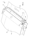
Figure 2 is a fragmentary detail perspective view of the draper header ofFigure 1 showing the roller arrangement. -
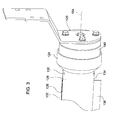
Figure 3 is a fragmentary detail perspective view of the roller arrangement ofFigure 2 . -
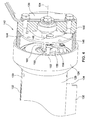
Figure 4 is a fragmentary detail perspective view of the roller arrangement ofFigures 2 and3 with the housing cut away. -
Figure 5 is a fragmentary detail perspective view of the roller arrangement ofFigures 2-4 with the roller cut away. - As used herein, the terms "forward", "front", "in front of", and the like refer to a direction parallel to the direction of travel of the combine as it harvests crop. The terms "rearward", "rear", "behind", and the like refer to a direction opposite to the direction of travel of the combine as it harvests crops. The terms "lateral", "laterally", and the like refer to a direction that is generally horizontal and perpendicular to the direction of travel of the combine as it harvests crops.
- In
Figure 1 , adraper header 100 includes aleft side conveyor 102, aright side conveyor 104, acenter conveyor 106, afeed roller 108, and areciprocating knife 110, all supported on aframe 112. A leftside stripper roller 103 and a rightside stripper roller 105 are provided - The
draper header 100 is supported on a combine (not shown) and is carried to the field in a direction "V" to harvest crops. The reciprocatingknife 110 is elongate and extends substantially the entire width of thedraper header 100 severs the crop plants near their roots. The crop plants fall backwards on theleft side conveyor 102, theright side conveyor 104, and thecenter conveyor 106. - The three conveyors are of an endless belt type, comprising a
web 114 of elastomer-reinforced fabric to which a plurality ofelongate cleats 116 are fixed. Eachweb 114 is supported and conveyed on a plurality of rollers (not shown). -
Figure 2 shows a detail portion of theright side conveyor 104 and thecenter conveyor 106, together with the rightside stripper roller 105. Theleft side conveyor 102 and the leftside stripper roller 103 are identically constructed but in mirror image relation. Theleft side conveyor 102 and leftside stripper roller 103 are not described herein for reasons of convenience. - The right
side stripper roller 105 is supported on two brackets: afront bracket 120 and therear bracket 118. Adrive roller 122 rests against and drives adrive wheel 124 that forms a part of and is disposed at one end of the rightside stripper roller 105. Thedrive roller 122 rests against theweb 114 of theright side conveyor 104. As theright side conveyor 104 runs, theweb 114 drives thedrive roller 122, which in turn drives thedrive wheel 124 in rotation. The rightside stripper roller 105 therefore is driven at the same speed as theright side conveyor 104. - In
Figure 3 , thedrive wheel 124 is fixed to two hemispherical shells, a firsthemispherical shell 128 and a secondhemispherical shell 130. The hemispherical shells together with thedrive wheel 124 and a substantially similar wheel (not shown) disposed at the other end of the right side stripper roller 105 (which also is fixed to the hemispherical shells) together form an elongate tubular member that is generally circular in cross-section and has a hollow interior. - The two hemispherical shells are spaced slightly apart to define therebetween a first
elongate slot 132 and a secondelongate slot 134. These two elongate slots are disposed on opposite circumferential sides of the rightside stripper roller 105, and are directly opposite to each other. A firstelongate cleat 136 is slidably supported in and extends outward from the secondelongate slot 134. A secondelongate cleat 138 is slidably supported in and extends outward from the firstelongate slot 132. These two cleats are driven (described below) to be extended outward from and to be retracted inside the shells. Ahousing 140 is fixed to thefront bracket 120 with a plurality of bolts. Thehousing 140 is stationary and supports the elongate tubular member for rotation about a centralrotational axis 154. - In
Figure 4 , areciprocating drive 142 is shown. Thereciprocating drive 142 is disposed inside thehousing 140 and thedrive wheel 124. Thereciprocating drive 142 comprises acam 144 that defines acam track 146. Thecam 144 is fixed to thehousing 140 and therefore is stationary. Thereciprocating drive 142 also comprises acam roller 148 that is disposed to rest against and follow thecam track 146. Thecam roller 148 is pivotally coupled to an inner end of afirst link 150. An outer end of thefirst link 150 is pivotally coupled to asupport 152, that in turn is fixed to thedrive wheel 124. Asecond link 156 has an inner end that is pivotally coupled to thecam roller 148. An outer end of thesecond link 156 is pivotally coupled to anarm 158 that extends outward from ashaft 160. - As the
drive wheel 124 is driven in rotation, thecam roller 148 is rotated about the inside of thehousing 140, resting against thecam track 146. As thecam roller 148 rotates, it moves radially inward and outward from the centralrotational axis 154. This inward and outward rotation causes the arm 158 (and hence the shaft 160) to be angularly advanced and retarded with respect to thedrive wheel 124, the firsthemispherical shell 128, and the secondhemispherical shell 130. - In
Figure 5 , asecond arm 162 is fixed to theshaft 160 and rotates together with theshaft 160 as it is advanced and retarded with respect to thedrive wheel 124. Athird link 164 is pivotally coupled to an outer end of thesecond arm 162 at one end. Thethird link 164 is pivotally coupled to apin 166 at its other end. - The first
elongate cleat 136 and the secondelongate cleat 138 are fixed to and extend outward from anelongate tube 168. Theelongate tube 168, the firstelongate cleat 136 and the secondelongate cleat 138 extend substantially the entire length of the rightside stripper roller 105. Theshaft 160 passes through theelongate tube 168 and extends substantially the entire length of the rightside stripper roller 105. Theelongate tube 168 defines an oblong hole through which theshaft 160 extends. - As the
shaft 160 advances and retards with respect to thedrive wheel 124, theshaft 160 oscillates the outer end of thesecond arm 162 back and forth with respect to thedrive wheel 124, thehemispherical shells elongate tube 168. This oscillating motion, in turn, oscillates thethird link 164. Thethird link 164, in turn, pulls and pushes on thepin 166. Thepin 166 is fixed to theelongate tube 168. As a result, the movement of thecam roller 148 against thecam track 146 causes theelongate tube 168 to slide up and down on theshaft 160, which in turn causes theelongate tube 168 to alternately (a) extend theelongate cleat 138 and retract theelongate cleat 136 simultaneously, and (b) retract theelongate cleat 138 and extend theelongate cleat 136 simultaneously. - The
cam track 146 is preferably formed to extend each of theelongate cleats right side conveyor 104. As the rightside stripper roller 105 continues its rotation, rotating the slots inward and downward toward thecenter conveyor 106, thecam track 146 is preferably formed to retract each cleat, thereby releasing the cut crop material, stripping the cut crop material from the cleat, and preventing the cleat from holding the cut crop material and wrapping it around the rightside stripper roller 105. Since the cleats extend from opposite sides of the rightside stripper roller 105, as onecleat other cleat 136, 138 (which is disposed on the opposite side of the right side stripper roller 105) is simultaneously retracted an equal amount. - An
outer end 170 of theshaft 160 is supported in abearing 172. Thebearing 172 supports theouter end 170 in an inner race of thebearing 172. The outer race of bearing 172 is supported inside thehousing 140, which is stationary. This arrangement permits theshaft 160 to be supported by bearing 172 and to freely rotate about its centralrotational axis 154. Theshaft 160 is also supported in abearing 174. Thebearing 174 supports theshaft 160 in its inner race. The outer race of bearing 174 is fixed to thedrive wheel 124. This arrangement permits theshaft 160 to be supported by bearing 172 and to rotate relative to thehousing 140 and thereby to advance and retard its rotational position about the centralrotational axis 154 with respect to thedrive wheel 124. A similar bearing arrangement is provided at the other (rear) end of the rightside stripper roller 105 to support the other end of the rightside stripper roller 105 for rotation and also to permit theshaft 160 to advance and retard with respect to thedrive wheel 124. - The arrangements illustrated and described herein are merely examples of one way to create the invention. Someone skilled in the art of this invention would readily see other ways to create the invention that would fall within the scope of the claims. It is the claims that define the scope of the invention.
Claims (12)
- A stripper roller (103, 105) for a draper header (100) comprising:an elongate tubular member (124, 128, 130) defining at least one elongate slot (132, 134);at least one elongate cleat (136, 138) disposed inside the elongate tubular member (124, 128, 130) that is configured to be extended from and retracted into the at least one elongate slot (132, 134); anda reciprocating drive (142) that is coupled to the at least one elongate cleat (136, 138) and is configured to extend and retract the at least one elongate cleat (136, 138) as the stripper roller (103, 105) rotates about its central rotational axis (154).
- The stripper roller (103, 105) of Claim 1, wherein the at least one elongate cleat (136, 138) comprises at least two elongate cleats (136, 138), and wherein the at least one elongate slot (132, 134) comprises at least two elongate slots (132, 134).
- The stripper roller (103, 105) of Claim 2, wherein the at least two elongate slots (132, 134) are disposed on opposite sides of the elongate tubular member (124, 128, 130), and further wherein each of the at least two elongate slots (132, 134) supports a corresponding one of the at least two elongate cleats (136, 138).
- The stripper roller (103, 105) of Claim 2, wherein the at least two elongate cleats (136, 138) are fixed together such that one of said at least two elongate cleats (136, 138) moves to extend from the elongate tubular member (124, 128, 130) as another of said at least two elongate cleats (136, 138) moves to retract into the elongate tubular member (124, 128, 130) during at least a portion of one complete revolution of the stripper roller (103, 105).
- The stripper roller (103, 105) of Claim 1, wherein the reciprocating drive (142) comprises a cam roller (148) and a cam track (146), and further wherein the cam roller (148) is disposed to follow the cam track (146).
- The stripper roller (103, 105) of Claim 5, wherein the cam roller (148) is operationally coupled to the at least one elongate cleat (136, 138) to extend and retract the at least one elongate cleat (136, 138) as the stripper roller (103, 105) rotates.
- The stripper roller (103, 105) of Claim 5, wherein the cam roller (148) is engaged with a shaft (160) to advance and retard the shaft (160) based upon a position of the cam roller (148) on the cam track (146).
- The stripper roller (103, 105) of Claim 1, wherein the elongate tubular member (124, 128, 130) comprises at least one hemispherical shell (128, 130) wherein said at least one hemispherical shell (128, 130) forms an outer elongate surface of the stripper roller (103, 105).
- The stripper roller (103, 105) of Claim 8, wherein the at least one hemispherical shell (128, 130) comprises at least two hemispherical shells (128, 130), and further wherein the at least one elongate slot (132, 134) is defined by a space between the at least two hemispherical shells (128, 130).
- The stripper roller (103, 105) of Claim 1, wherein the at least one elongate slot (132, 134) extends substantially an entire length of the stripper roller (103, 105).
- The stripper roller (103, 105) of Claim 1, wherein the reciprocating drive (142) is configured to hold the at least one elongate cleat (136, 138) in an extended position when the at least one elongate cleat (136, 138) is disposed proximate to the top of the stripper roller (103, 105), and is configured to hold the at least one elongate cleat (136, 138) in a retracted position when the at least one elongate cleat (136, 138) is proximate to the bottom of the stripper roller (103, 105).
- A draper header (100) comprising a left side conveyor (102), a right side conveyor (104), a center conveyor (106), a first stripper roller (103) that is disposed at an inner end of the left side conveyor (102), and a second stripper roller (105) that is disposed at an inner end of the right side conveyor (104), wherein the first stripper roller (103) and the second stripper roller (105) are in accordance with Claim 1.
Applications Claiming Priority (1)
| Application Number | Priority Date | Filing Date | Title |
|---|---|---|---|
| US14/153,493 US20150195992A1 (en) | 2014-01-13 | 2014-01-13 | Draper Roller with Active Retracting Cleat Crop Stripper |
Publications (1)
| Publication Number | Publication Date |
|---|---|
| EP2896284A1 true EP2896284A1 (en) | 2015-07-22 |
Family
ID=52000626
Family Applications (1)
| Application Number | Title | Priority Date | Filing Date |
|---|---|---|---|
| EP14193028.9A Withdrawn EP2896284A1 (en) | 2014-01-13 | 2014-11-13 | Draper roller with active retracting cleat crop stripper |
Country Status (5)
| Country | Link |
|---|---|
| US (1) | US20150195992A1 (en) |
| EP (1) | EP2896284A1 (en) |
| AU (1) | AU2014280963A1 (en) |
| BR (1) | BR102014033069A2 (en) |
| CA (1) | CA2876774A1 (en) |
Cited By (3)
| Publication number | Priority date | Publication date | Assignee | Title |
|---|---|---|---|---|
| US20180343882A1 (en) * | 2015-11-29 | 2018-12-06 | Hadasit Medical Research Services And Development Ltd. | Supplementation of milk formulas with microvesicles isolated from milk |
| EP3434095A1 (en) * | 2017-07-27 | 2019-01-30 | Macdon Industries Ltd. | Header for a crop harvesting machine |
| US20220000031A1 (en) * | 2018-11-16 | 2022-01-06 | Cnh Industrial America Llc | Harvester header with lateral belt roller mount |
Families Citing this family (7)
| Publication number | Priority date | Publication date | Assignee | Title |
|---|---|---|---|---|
| US10412891B2 (en) * | 2017-01-23 | 2019-09-17 | Cnh Industrial America Llc | Draper belt system with differently sized rollers |
| US10349580B2 (en) * | 2017-07-06 | 2019-07-16 | Mac Don Industries Ltd. | Draper header for attachment to a harvesting machine |
| US10477767B2 (en) | 2017-07-28 | 2019-11-19 | Deere & Company | Draper platform with removable central roller baffle |
| US10477770B2 (en) | 2017-07-28 | 2019-11-19 | Deere & Company | Draper platform with reconfigurable central roller baffle |
| US10390486B2 (en) * | 2017-10-11 | 2019-08-27 | Deere & Company | Polymer used as draper belt contact surface |
| CN110182601B (en) * | 2019-07-01 | 2024-02-09 | 苏州工业职业技术学院 | A steel pipe loading device |
| CN121040294B (en) * | 2025-11-06 | 2026-02-03 | 山西省农业机械发展中心 | Corn harvester and working method thereof |
Citations (3)
| Publication number | Priority date | Publication date | Assignee | Title |
|---|---|---|---|---|
| DE1507169A1 (en) * | 1966-09-03 | 1969-12-18 | Bautz Gmbh Josef | Feed drum for combine harvester |
| US20020129591A1 (en) | 2001-03-19 | 2002-09-19 | Patterson Roger L. | Crop stripper for the crop transport draper of a header |
| US7872364B1 (en) * | 2009-08-15 | 2011-01-18 | Wayne Embree | Fluid driven energy generator |
-
2014
- 2014-01-13 US US14/153,493 patent/US20150195992A1/en not_active Abandoned
- 2014-11-13 EP EP14193028.9A patent/EP2896284A1/en not_active Withdrawn
- 2014-12-24 AU AU2014280963A patent/AU2014280963A1/en not_active Abandoned
- 2014-12-30 BR BR102014033069A patent/BR102014033069A2/en not_active IP Right Cessation
-
2015
- 2015-01-06 CA CA2876774A patent/CA2876774A1/en not_active Abandoned
Patent Citations (3)
| Publication number | Priority date | Publication date | Assignee | Title |
|---|---|---|---|---|
| DE1507169A1 (en) * | 1966-09-03 | 1969-12-18 | Bautz Gmbh Josef | Feed drum for combine harvester |
| US20020129591A1 (en) | 2001-03-19 | 2002-09-19 | Patterson Roger L. | Crop stripper for the crop transport draper of a header |
| US7872364B1 (en) * | 2009-08-15 | 2011-01-18 | Wayne Embree | Fluid driven energy generator |
Cited By (5)
| Publication number | Priority date | Publication date | Assignee | Title |
|---|---|---|---|---|
| US20180343882A1 (en) * | 2015-11-29 | 2018-12-06 | Hadasit Medical Research Services And Development Ltd. | Supplementation of milk formulas with microvesicles isolated from milk |
| US10874114B2 (en) * | 2015-11-29 | 2020-12-29 | Hadasit Medical Research Services And Development Ltd. | Supplementation of milk formulas with microvesicles isolated from milk |
| EP3434095A1 (en) * | 2017-07-27 | 2019-01-30 | Macdon Industries Ltd. | Header for a crop harvesting machine |
| US20220000031A1 (en) * | 2018-11-16 | 2022-01-06 | Cnh Industrial America Llc | Harvester header with lateral belt roller mount |
| US12514162B2 (en) * | 2018-11-16 | 2026-01-06 | Cnh Industrial America Llc | Harvester header with lateral belt roller mount |
Also Published As
| Publication number | Publication date |
|---|---|
| BR102014033069A2 (en) | 2016-05-24 |
| CA2876774A1 (en) | 2015-07-13 |
| AU2014280963A1 (en) | 2015-07-30 |
| US20150195992A1 (en) | 2015-07-16 |
Similar Documents
| Publication | Publication Date | Title |
|---|---|---|
| US20150195992A1 (en) | Draper Roller with Active Retracting Cleat Crop Stripper | |
| US2832187A (en) | Conveyor attachment for harvester platforms | |
| US8640434B2 (en) | Removable corn header snout | |
| US8387351B2 (en) | Harvester header bat reel assembly tensioning member | |
| US9974237B2 (en) | Threshing corn header with screw crop conveyors | |
| US20060201126A1 (en) | Crop harvesting header with crop divider members carried on the reel | |
| EP2769612A1 (en) | Frusto-conical conveyor with retracting fingers | |
| US9516816B2 (en) | Multiple drums conveyor for an agricultural platform | |
| EP2856854B1 (en) | Feeding mechanism of a header for a combine harvester | |
| US3333405A (en) | Cornstalk ejector for a combine header | |
| US4215527A (en) | Multi-row crop header with feed assist roller | |
| US3744224A (en) | Tobacco harvester | |
| US10806081B2 (en) | Crop deflector for a harvesting head | |
| KR101142927B1 (en) | Mower unit for crop harvesting and harvester having the same | |
| US20120055134A1 (en) | Gathering Auger with Independent Speed | |
| KR20160069072A (en) | Cutting device for combines | |
| US20190200528A1 (en) | Combine having conveyor chain slat assembly and method of harvesting crop thereof | |
| US12295291B2 (en) | Header for harvesting stalk-like plants with a picking gap oriented transversely to the direction of travel | |
| RU2294082C1 (en) | Method for corn harvesting and apparatus for performing the same | |
| US20240224867A9 (en) | Harvesting attachment for whole plant harvesting | |
| US2686396A (en) | Mower pickup attachment for forage harvesters | |
| US3754387A (en) | Tobacco harvester | |
| US2723522A (en) | Conveyor feeder mechanism for removing crop material cut and elevated by cooperative augers | |
| JP4524620B2 (en) | Combine | |
| JP2001178232A (en) | Harvester |
Legal Events
| Date | Code | Title | Description |
|---|---|---|---|
| PUAI | Public reference made under article 153(3) epc to a published international application that has entered the european phase |
Free format text: ORIGINAL CODE: 0009012 |
|
| 17P | Request for examination filed |
Effective date: 20141113 |
|
| AK | Designated contracting states |
Kind code of ref document: A1 Designated state(s): AL AT BE BG CH CY CZ DE DK EE ES FI FR GB GR HR HU IE IS IT LI LT LU LV MC MK MT NL NO PL PT RO RS SE SI SK SM TR |
|
| AX | Request for extension of the european patent |
Extension state: BA ME |
|
| STAA | Information on the status of an ep patent application or granted ep patent |
Free format text: STATUS: THE APPLICATION IS DEEMED TO BE WITHDRAWN |
|
| 18D | Application deemed to be withdrawn |
Effective date: 20160123 |