EP2895686B1 - Well treatment device, method, and system - Google Patents
Well treatment device, method, and system Download PDFInfo
- Publication number
- EP2895686B1 EP2895686B1 EP13837480.6A EP13837480A EP2895686B1 EP 2895686 B1 EP2895686 B1 EP 2895686B1 EP 13837480 A EP13837480 A EP 13837480A EP 2895686 B1 EP2895686 B1 EP 2895686B1
- Authority
- EP
- European Patent Office
- Prior art keywords
- seal
- collet
- treatment
- disposed
- shows
- Prior art date
- Legal status (The legal status is an assumption and is not a legal conclusion. Google has not performed a legal analysis and makes no representation as to the accuracy of the status listed.)
- Not-in-force
Links
Images








Classifications
-
- E—FIXED CONSTRUCTIONS
- E21—EARTH OR ROCK DRILLING; MINING
- E21B—EARTH OR ROCK DRILLING; OBTAINING OIL, GAS, WATER, SOLUBLE OR MELTABLE MATERIALS OR A SLURRY OF MINERALS FROM WELLS
- E21B34/00—Valve arrangements for boreholes or wells
- E21B34/06—Valve arrangements for boreholes or wells in wells
- E21B34/063—Valve or closure with destructible element, e.g. frangible disc
-
- E—FIXED CONSTRUCTIONS
- E21—EARTH OR ROCK DRILLING; MINING
- E21B—EARTH OR ROCK DRILLING; OBTAINING OIL, GAS, WATER, SOLUBLE OR MELTABLE MATERIALS OR A SLURRY OF MINERALS FROM WELLS
- E21B23/00—Apparatus for displacing, setting, locking, releasing or removing tools, packers or the like in boreholes or wells
- E21B23/01—Apparatus for displacing, setting, locking, releasing or removing tools, packers or the like in boreholes or wells for anchoring the tools or the like
-
- E—FIXED CONSTRUCTIONS
- E21—EARTH OR ROCK DRILLING; MINING
- E21B—EARTH OR ROCK DRILLING; OBTAINING OIL, GAS, WATER, SOLUBLE OR MELTABLE MATERIALS OR A SLURRY OF MINERALS FROM WELLS
- E21B33/00—Sealing or packing boreholes or wells
- E21B33/10—Sealing or packing boreholes or wells in the borehole
- E21B33/12—Packers; Plugs
-
- E—FIXED CONSTRUCTIONS
- E21—EARTH OR ROCK DRILLING; MINING
- E21B—EARTH OR ROCK DRILLING; OBTAINING OIL, GAS, WATER, SOLUBLE OR MELTABLE MATERIALS OR A SLURRY OF MINERALS FROM WELLS
- E21B34/00—Valve arrangements for boreholes or wells
- E21B34/06—Valve arrangements for boreholes or wells in wells
-
- E—FIXED CONSTRUCTIONS
- E21—EARTH OR ROCK DRILLING; MINING
- E21B—EARTH OR ROCK DRILLING; OBTAINING OIL, GAS, WATER, SOLUBLE OR MELTABLE MATERIALS OR A SLURRY OF MINERALS FROM WELLS
- E21B34/00—Valve arrangements for boreholes or wells
- E21B34/06—Valve arrangements for boreholes or wells in wells
- E21B34/10—Valve arrangements for boreholes or wells in wells operated by control fluid supplied from outside the borehole
- E21B34/102—Valve arrangements for boreholes or wells in wells operated by control fluid supplied from outside the borehole with means for locking the closing element in open or closed position
-
- E—FIXED CONSTRUCTIONS
- E21—EARTH OR ROCK DRILLING; MINING
- E21B—EARTH OR ROCK DRILLING; OBTAINING OIL, GAS, WATER, SOLUBLE OR MELTABLE MATERIALS OR A SLURRY OF MINERALS FROM WELLS
- E21B34/00—Valve arrangements for boreholes or wells
- E21B34/06—Valve arrangements for boreholes or wells in wells
- E21B34/10—Valve arrangements for boreholes or wells in wells operated by control fluid supplied from outside the borehole
- E21B34/102—Valve arrangements for boreholes or wells in wells operated by control fluid supplied from outside the borehole with means for locking the closing element in open or closed position
- E21B34/103—Valve arrangements for boreholes or wells in wells operated by control fluid supplied from outside the borehole with means for locking the closing element in open or closed position with a shear pin
-
- E—FIXED CONSTRUCTIONS
- E21—EARTH OR ROCK DRILLING; MINING
- E21B—EARTH OR ROCK DRILLING; OBTAINING OIL, GAS, WATER, SOLUBLE OR MELTABLE MATERIALS OR A SLURRY OF MINERALS FROM WELLS
- E21B41/00—Equipment or details not covered by groups E21B15/00 - E21B40/00
- E21B41/005—Waste disposal systems
- E21B41/0057—Disposal of a fluid by injection into a subterranean formation
-
- E—FIXED CONSTRUCTIONS
- E21—EARTH OR ROCK DRILLING; MINING
- E21B—EARTH OR ROCK DRILLING; OBTAINING OIL, GAS, WATER, SOLUBLE OR MELTABLE MATERIALS OR A SLURRY OF MINERALS FROM WELLS
- E21B2200/00—Special features related to earth drilling for obtaining oil, gas or water
- E21B2200/06—Sleeve valves
-
- E—FIXED CONSTRUCTIONS
- E21—EARTH OR ROCK DRILLING; MINING
- E21B—EARTH OR ROCK DRILLING; OBTAINING OIL, GAS, WATER, SOLUBLE OR MELTABLE MATERIALS OR A SLURRY OF MINERALS FROM WELLS
- E21B2200/00—Special features related to earth drilling for obtaining oil, gas or water
- E21B2200/08—Down-hole devices using materials which decompose under well-bore conditions
Definitions
- the invention generally relates to tools for treatment of well-bores that are used, for example, in the exploration and production of oil and gas.
- the present invention is related to a system for selectively treating zones in a cased well-bore, the system comprising: a downhole, having a body, an inner bore therethrough, an inner surface of the body formed by the inner bore, and an outer surface; at least one treatment port disposed on the outer surface of the body; means for selectively isolating the inner bore from the outer surface, the means for selectively isolating the inner bore comprising a sliding sleeve disposed within the inner bore of the body; an annular chamber between the inner surface of the body and an outer surface of the sliding inner sleeve; means for maintaining the inner sliding sleeve in an open position, the means for maintaining disposed within the annular chamber; and means for maintaining the inner sliding sleeve in a closed position.
- Such a system is known from US 2011/308817 A1 pertaining to a ported housing that may be connected along a casing string and the method for use of the ported housing in fracturing and/or treating multiple zones in a well.
- a sleeve is connected to the ported housing and may be moved between an initial position that prevents fluid flow through the ports of the housing and second position that permits fluid flow through the ports.
- a bottom hole assembly may be connected to the sleeve by an anchor.
- a packer element may create a seal between the bottom hole assembly and the sleeve permitting a pressure differential across the packer element to move bottom hole assembly down the casing moving the sleeve to the second position. In the second position, the formation adjacent to the ported housing may be stimulated and/or treated.
- the system of the present invention is characterized by means for isolating, the means comprising the annular chamber, and by the chamber in isolation from the inner bore and the outer surface.
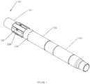
- Figure 1 shows a 3-D perspective external view of the treatment valve assembly incorporating one example of the present invention.
- Figure 1 is an external view of the Treatment Valve 100, and shows, in one example, its three major external components.
- a Ported Top Sub 101 is attached to a Bottom Sub 103 by a Housing member 102.
- these components form the tool body.
- these parts making up the body of the tool are secured together with threaded connections.
- Treatment Valve 100 is deployed into the wellbore by placing it in-line with a production string. In one example, this is done by threading Bottom Sub 103 of assembled Treatment Valve 100 into the production string as it is deployed into the wellbore, then threading the production string into Ported Top Sub 101, and continuing to deploy the production string into the wellbore.
- Treatment Port(s) 208 are used to communicate fluids from the inside of the Treatment Valve 100 to the outside, similar in function to perforations that are placed in production strings with explosive charges.
- Treatment Port(s) 208 are oval in shape, and in that example the length and width of the Treatment Port 208 determine the flow area and velocity profile of the treatment fluid placed through the Treatment Port(s) 208.
- the size and shape of Treatment Port(s) 208 and the number of Treatment Ports 208 are selected to optimize the placement of the treatment fluid into the formation(s).
- Each formation encountered has unique properties, which may require the size and shape of the Treatment Port(s) 208 to be adjusted to facilitate placing the desired treatment.
- Lubrication Ports/Plugs 105 are used to provide lubrication to the actuating parts of the Treatment Valve to increase the reliability of the assembly.
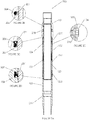
- Figure 2A shows a cross-sectional view of the treatment valve assembly incorporating one example of the present invention in the closed valve position.
- Figure 2A is a cross-sectional view of the assembled Treatment Valve 100 in the closed position (denoted as Treatment Valve 200), as it is run into the wellbore.
- An Inner Sleeve 201 runs the length of the Treatment Valve 200 from the Treatment Port Seal Assembly as shown in Figure 2B , to the Lower Chamber Seal Assembly as shown in Figure 2D .
- Inner Sleeve 201 serves two functions in this position. First, it isolates the inside of Treatment Valve 200 from the outside of the Treatment Valve 200 by isolating Treatment Port 208. Second, it is the inner member that forms the inner wall of the Locking Chamber, 299.
- a Collet 202 is radially disposed on the outside of the Inner Sleeve 201 and, in one example, is used to maintain the Treatment Valve in the open position. Examples of Collet 202, and its function are further detailed in Figures 5A-C , 6A-E , 8A-D , 9A-D .
- Orings 203 are placed to seal the threaded connection at the Ported Top Sub 101 and Housing 102 and the threaded connection at Housing 102 and Bottom Sub 103.
- a Locator Groove 211 is placed radially inward in Bottom Sub 103, located longitudinally near the bottom of the sub, and, in one example, is used to provide a means of locating the sleeve.
- a mechanical collar locator is known in the art as a means of locating upsets in wellbore tubulars, and can be used to locate the treatment valve assembly (the tool) by catching in Locator Groove 211.
- Figure 2B shows a cross-sectional detail-view of the Treatment Port Seal Assembly.
- Figure 2B shows the Treatment Port Seal Assembly which is radially disposed of inwardly in Ported Top Sub 101, located longitudinally above the Treatment Port 208 and is comprised of an Energizing Ring, 204 and a Seal Ring 205 which seals on Inner Sleeve 201.
- Energizer Ring 204 is a Viton oring
- Seal Ring 205 is a carbon filled Teflon ring.
- This seal assembly is capable of holding pressure in both directions, which is to say that it will maintain the isolation of the inside and outside of the Treatment Valve 100, regardless of which pressure is higher.
- Seal Ring 205 seals on the outside diameter of Inner Sleeve 201 and is well-suited for this application because it will not roll or be pulled out of the seal groove when pressure is applied and when Inner Sleeve 201 is shifted downward.
- Seal Ring 205 provides the required seal by being forced onto Inner Sleeve 201.
- Energizer Ring 204 is used to provide the force to engage the seal properly. In typical oring seals, the oring is compressed, which forces it onto the two parts being sealed; however, typical oring seals are known to roll in the groove and/or pull out of the groove when a part is moved under pressure.
- two individual seals, Seal Ring 205 and Energizer Ring 204 combine into the seal assembly (shown in Figure 2B ) to yield a seal that is much better suited to the application of the Treatment Valve 100.
- Figure 2C shows a cross-sectional detail-view of the Upper Chamber Seal Assembly.
- Figure 2C shows the Upper Chamber Seal Assembly which is radially disposed of inwardly with the open face of the seal oriented upward in Ported Top Sub 101, located longitudinally below the Treatment Port 208, and is comprised of a Lip Seal 206 and a Backup Ring, 207.
- Lip Seal 206 is a Viton seal and Backup Ring 207 is a Moly Glass Teflon Ring.
- Lip Seal 206 seals on Inner Sleeve 201 and is capable of holding pressure in only one direction.
- lip seals are available in a variety of configurations and offered under a variety of commercial names, such as, lip seals and U cup seals.
- a predominate, defining characteristic of this type of seal is an open face elastomeric feature that is oriented towards the applied pressure.
- an energizer is placed in the open face to force the lip onto the part being sealed.
- Example energizers include springs, orings and X rings.
- Backup Ring 207 is placed on the low pressure side of the seal, and, in one example, is used to provide additional support to Lip Seal 206, increasing the working pressure of the seal.
- Elastomeric seals are susceptible to extrusion, which is to say they push out into the gap between the parts being sealed.
- a seal will not hold the applied pressure and/or will interfere with the movement of the parts of the assembly when the seal extrudes through a gap to a point where it no longer is compressed onto the parts or is pulled out of the seal groove when the sealing parts are moved.
- a backup ring for example Backup Ring 207
- the lip seal configuration is particularly suited for this application because it is a pressure energized design, meaning that applied pressure to the open face acts to further engage Lip Seal 206 on Inner Sleeve 201.
- a primary function of the seal is to isolate Locking Chamber 299 from the external wellbore pressure on the outside of Treatment Valve 100.
- Figure 2D shows a cross-sectional detail-view of the Lower Chamber Seal Assembly.
- the Lower Chamber Seal is radially disposed of inwardly with the open face of the seal oriented downward in the Bottom Sub 103 and located longitudinally near the top of the Bottom Sub 103 where it will engage Inner Sleeve 201 while Treatment Valve 100 is in the closed position 200.
- the Lower Chamber Seal is comprised of the same components as the Upper Chamber Seal for the same functionality.
- FIG. 2E shows a cross-sectional detail-view of the Shear Screw in Housing.
- Figure 2E shows Shear Screw 104 engaged in both Housing member 102 and Inner Sleeve 201.
- Shear Screw 104 is placed radially on the exterior of Housing member 102 and is located longitudinally near the top where it can engage a Shear Screw Groove 601 of the Inner Sleeve 201.
- Shear Screw 104 is used to maintain Inner Sleeve 201 in the closed position until a predetermined downward force is applied to Inner Sleeve 201, thus shearing the screws and allowing relative movement of Inner Sleeve 201 inside Treatment Valve 100.
- Shear Screw(s) 104 used, in one example, are self sealing.
- an Oring Seal 210 is affixed to Shear Screw 104, in a groove, and provides isolation in both directions.
- Oring Seal 210 in made of Viton. It is important to note that in one preferred example, the seal is maintained even after the screw itself is sheared during operation.
- Locking Chamber 299 is an annular region of the tool where features related to retaining Treatment Valve 100 in the desired closed and locked positions are located.
- the Locking Chamber 299 is sealed from all wellbore fluids and associated debris to ensure that the locking features remain free of debris to enhance the reliability of operation.
- Locking Chamber 299 is constructed such that it is a constant-volume chamber, meaning that the volume of the chamber does not change when Treatment Valve 100 (inner sliding sleeve 201) is moved through its various positions.
- Locking Chamber 299 is defined by four major components: Ported Top Sub 101, Housing member 102, Bottom Sub 103, and Inner Sleeve 201.
- Inner Sleeve 201 defines an inner wall of the annular area and the combination of the interior surface walls of Ported Top Sub 101, Housing member 102, and Bottom Sub 103 define an outer wall of the annular area.
- the annular region is sealed on the up-hole end by the Upper Chamber Seal Assembly, as shown in Figure 2C , and the Oring 203 at the threaded connection of Ported Top Sub 101 and Housing member 102.
- the down-hole end of Locking Chamber 299 is sealed by the Lower Chamber Seal, as shown in Figure 2D , and the other Oring 203 at the threaded connection of Housing member 102 and Bottom Sub 103.
- the final seal(s) isolating Locking Chamber 299 include an Oring Seal 210, located on Shear Screw(s) 104.
- this chamber is an atmospheric chamber, meaning that the pressure in Locking Chamber 299 is maintained at the atmospheric pressure when the tool was assembled. This can result in particularly high pressure differentials across the Upper and Lower Chamber Seals, as shown in Figures 2C and 2D . Consequently, the pressure energized design of Lip Seal 206 utilized in the Upper and Lower Chamber Seals, as shown in Figures 2C and 2D , is considered to greatly improve the overall reliability of Treatment Valve 100.
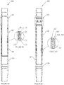
- Figure 3 shows a cross-sectional view of the treatment valve assembly (the tool) incorporating one example of the present invention in the open and locked position.
- the Figure 3 cross-sectional view of the assembled Treatment Valve 100, in the open and locked position 300 is the final position of Treatment Valve 100 after being actuated and the treatment placed. This position is attained by applying a downward force to Inner Sleeve 201 which is sufficient to shear Shear Screw(s) 104. Once Shear Screw(s) 104 are sheared, Inner Sleeve 201 moves down and disengages the Treatment Port Seal Assembly, as shown in Figure 2B , exposing Treatment Ports 208. Treatment Ports 208 are exposed to provide fluid access to the reservoir behind the production string, and communicate the inside of the production string to the fluids in the reservoir. This communication enables both placing the treatment and producing the reservoir.
- Figure 4A shows a cut-away partial 3-D perspective view of, in one example, the exterior of the treatment valve assembly, detailing the Treatment Port, Treatment Port Recess and Treatment Port Cover prior to placement.
- Figure 4A shows a detailed view of Treatment Port 208 and Treatment Port Cover 402, which is used to shield Treatment port 208 from debris while being run in the wellbore and maintaining the lubrication of the valve.
- a Treatment Port Recess 401 in which Treatment Port Cover 402 is placed.
- Figure 4B shows a cut-away partial 3-D perspective view of, in one example, the exterior of the treatment valve assembly (the tool), detailing the Treatment Port Cover installed in the Treatment Port Recess, over the Treatment Valve.
- Figure 4B shows Treatment Port Cover 402 placed in Treatment Port Recess 401.
- Treatment Port Cover 402 is adhered to Treatment Port Recess 401 by a suitable adhesive or solder. While being run in the wellbore, Treatment Valve 100 will be in contact with the wellbore or other tubular walls in both a sliding and rotating motion; therefore, in one example, Treatment Port Recess 401 is important because it protects Treatment Port Cover 402 from being pulled off Treatment Valve 100 due to contact with the wellbore or other tubulars in which it is conveyed through.
- the treatment port cover thickness and material combination provide a limited strength that can be ruptured by applying pressure from fluids pumped from the inner bore.
- Treatment Port Cover 402 is constructed from a material that is dissolvable by a fluid that is compatible with the formation.
- the dissolvable fluid is selected from those fluids that are capable of dissolving the cover and yet are non-damaging to the wellbore formation of interest.
- the dissolving fluid is 15% Hydrochloric Acid.
- the treatment port cover thickness and material combination provide a limited strength that can be ruptured, after applying the dissolving fluid, by applying pressure from fluids pumped from the inner bore.
- Treatment Port Cover 402 is constructed of aluminum and, in further example, is .007 inch thick with, in further example, two 1/16 inch holes placed on the centerline. In one example, the holes placed in Treatment Port Cover 402 facilitate contact of the dissolving fluid with Treatment Port Cover 402, in one example, by preventing a dead volume. In one example, Treatment Port Cover 402 is constructed, positioned, and arranged to keep debris out of the valve actuation area. In one example, Treatment Port Cover 402 is constructed, positioned, and arranged to maintain the lubrication placed in Treatment Valve 100, at surface, which is introduced through Lubrication Port/Plug(s) 105.
- Figure 5A shows a 3-D perspective view of one example of the Collet used to lock the Treatment Valve in the open position.
- Figure 5A is an overall view of Collet 202 which is used to lock Treatment Valve 100 in the open position 300.
- Collet 202 is a cylindrical component that is constructed to create individual Collet Fingers 501 which, in one example, is comprised of sixteen individual Collet Fingers 501, in one example, disposed in longitudinal orientation circumferentially about the axis of the collet.
- Collet 202 is a hollow cylindrical member.
- Collet 202 is a unitary cylindrical member.
- Collet 202 is shaped, positioned, and arranged to allow it to slide through Housing member 102, which, in one example, has a smaller inside diameter than the outside diameter of Collet 202. In one example, this is accomplished by machining individual Collet Fingers 501, which can be viewed as individual cantilevered beams that will deflect under load. This deflection allows Collet Finger 501 to deflect inward and pass through a smaller diameter restriction of Housing 102 and spring back to the original outside diameter past the restriction. In one example, an additional feature of Collet 202 is that is can support longitudinal loads once engaged in a suitable retaining groove.
- the length, width and thickness of Collet Fingers 501 are selected to match its operational requirements, as these parameters determine the stress induced in individual Collet Fingers 501 when deflected inward while shifting the Treatment Valve 100.
- the combination of those characteristics and the yield strength of the material used to construct Collet 202 are selected to ensure that Collet Finger 501 is flexible enough to spring back after being compressed, which is to say that the stress due to the applied inward deflection does not exceed the yield strength of the material used to construct Collet 202.
- Collet Finger 501 is of substantial enough strength to withstand the longitudinal loads applied during operation.
- Figure 5B shows a Cross-sectional view of one example of the Collet.
- Figure 5B shows the Collet Thread 502, used to fix Collet, 202 to Inner Sleeve 201 at Inner Sleeve Thread 602.
- FIG. 5C shows a cut-away partial 3-D perspective detail-view of, in one example, the Collet Head 503.
- a Collet Compression Face 504 is used to compress the collet in the downward movement by contacting Housing Compression Face 702.
- Compression Face 504 is a surface on the free end of the cantilevered beam (finger), the compression surface forming part of the head that protrudes radially outward relative to the axis of the collet.
- Collet Locking Face 505 is machined to match a Housing Locking Face 703 in Housing member 102, preventing Treatment Valve 100 from closing after being opened.
- Locking Face 505 is a surface on the free end of the cantilevered beam (finger), the locking surface forming part of the head that protrudes radially outward relative to the axis of the collet.
- the locking surface is disposed with a negative rake, for example, disposed at an angle less than 90 degrees from the longitudinal axis and in the direction of the first end of the beam, as illustrated in figure 5C .
- Collet Locking Face 505 has an angle of 30 degrees, for example, 30 degrees from the longitudinal axis and in the direction of the first end of the beam.
- Collet Locking Face 505 has an angle of 35 degree, for example, 35 degrees from the longitudinal axis and in the direction of the first end of the beam.
- the term collet refers to the physical appearance of the member, but does not necessarily require the collet member to squeeze the inner sleeve for secure holding. Rather, in one example, the collet member is secured to the inner sleeve by other means, such as threads, and the collet member functions to provide outwardly expanding fingers to urge stops, or locking faces, outward towards the inner surface wall of the assembly housing or body.
- the fingers are compressible radially inwards, allowing locking faces to be longitudinally inserted in position, longitudinally past diameter restrictions on the inner face of the assembly housing/body.
- Figure 6A shows a 3-D perspective external view of one example of the Collet installed on the Inner Sleeve.
- Collet 202 is shown installed on Inner Sleeve 201.
- Collet 202 is placed radially on Inner Sleeve 201, longitudinally located on an Inner Sleeve Thread 602, with Collet Head(s) 503 oriented downward from Threads 502 and 602.
- Figure 6B shows a cross-sectional view of one example of the installed on the Inner Sleeve.
- Collet 202 is shown installed on Inner Sleeve 201.
- a Shear Screw Groove 601 is a groove radially placed on Inner Sleeve 201, placed longitudinally such that Shear Screws 104, inserted and retained in Housing 102, can be engaged.
- Figure 6C shows a cross-sectional detail-view of one example of threads affixing the Collet to the Inner Sleeve. Threads 502 and 602, as shown are used to affix Collet 202 to Inner Sleeve 201.
- Figure 6D shows a cross-sectional detail-view of one example of the Collet Head positioned over an Inner Sleeve Collet Relief Groove.
- Collet Head 503, as shown, is located on Inner Sleeve 201.
- the Inner Sleeve Collet Relief Groove 603 is a small relief placed on the exterior of Inner Sleeve 201 to allow for proper deflection of Collet Head 503 as it is compressed while moving longitudinally through Housing 102, such that Collet Head 503 does not contact Inner Sleeve 201 as the Treatment Valve 100 is moved from the closed position.
- Figure 6E - shows a cross-sectional detail-view of one example of the Inner Sleeve Landing Surface.
- An Inner Sleeve Landing Surface 604 is shown on Inner Sleeve 201, in one example, is used to limit the movement of Inner Sleeve 201 within Treatment Valve 100.
- Inner Sleeve Landing Surface 604 will come in contact with the Bottom Sub Landing Surface 901.
- Inner Sleeve Landing Surface 604 forms a contact shoulder against Bottom Sub Landing Surface 901 to limit further longitudinal movement of Inner Sleeve 201.
- FIG 7A shows a cross-sectional view of one example of the treatment assembly Housing member.
- Housing member 102 is shown with detail of a Housing Collet Relief Groove 701, which is a groove placed into Housing member 102, allowing Collet Finger(s) 501 (as shown in Figure 5A ) to be in a non-stressed state while Treatment Valve 100 is in the closed position 200.
- the placement of Collet Head 503 in Housing Collet Relief Groove 701 is shown in Figure 8B .
- a Housing Collet Compression Face 702 is shown, which acts on Collet Compression Face 504 (as shown in Figure 5C ) to bend Collet Finger(s) 501 (not shown) as the Treatment Valve, 100, is moved from the closed position, 200.
- FIG 7B shows a cross-sectional detail-view of one example of the Housing Locking Face.
- a Housing Locking Face 703 is matched to Collet Locking Face 505 (shown in Figure 5C ) to prevent Treatment Valve 100 from closing after actuation.
- the interaction of the two locking faces are further discussed using Figures 8D and 9B .
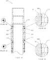
- Figure 8A shows a cross-sectional view of one example of the treatment valve assembly in the closed position.
- Treatment Valve 100 in the closed position 200 is included to show the location of Collet Head 502 relative to the treatment valve assembly in the closed position 200.
- FIG 8B shows a cross-sectional detail-view of one example of the Collet Head positioned in the Housing Collet Relief Groove.
- Collet Head 503 is shown disposed in Housing Collet Relief Groove 701, when Treatment Valve 100 is in the closed position, 200. This relief groove allows the Collet to be placed in the assembly without stressing the Collet Finger(s) 501.
- Collet Compression Face 504 contacts Housing Compression Face 702, forcing Collet Finger(s), 501 to deflect radially inward.
- Figure 8C shows a cross-sectional view of one example of the treatment valve assembly in the open and locked position.
- Treatment Valve 100 in the open and locked position 300, is included to show the location of Collet Head 503 relative to the treatment valve assembly in the open and locked position, 300.
- FIG 8D shows a cross-sectional detail-view of one example of the Collet Head positioned with the Collet Locking Face engaged with the Housing Locking Face.
- Collet Head 503 is shown disposed in Housing member 102, when the Treatment Valve 100 is in the open and locked position 300.
- Collet Locking Face 505 is in contact with Housing Locking Face 703. These two faces are in contact and, in one example, the 30 degree angle at which they are placed in the assembly prevent the Treatment Valve 100 from closing.
- An upward force placed on the Inner Sleeve 201 is transmitted to Collet 202 by the thread engagement at Collet Threads 502 and Seal Threads 602.
- Figure 9A shows a cross-sectional view of one example of the treatment valve assembly in the shouldered position.
- Treatment Valve 100 in the shouldered position 900, is included to show the location of Collet Head 503 relative to the treatment value assembly in the shouldered position 900.
- shouldered position 900 is defined by the contact of Inner Sleeve 201 and Bottom Sub 103, which prevents any further movement in the downward direction. Shouldered is meant to describe an arrangement where the two parts are touching but are not locked together.
- FIG. 9B shows a cross-sectional detail-view of one example of the Collet Head positioned in the Housing in the shouldered position.
- Collet Head 503 is shown disposed in Housing member 102 when the Treatment Valve 100 is in the shouldered position, 900.
- a Collet-Bottom Sub Gap 801 is formed by the space between Collet Head 503 and Bottom Sub 103.
- the shouldered position 900 is achieved when Inner Sleeve 201 comes in contact with Bottom Sub 103 and prevents further downward movement of Inner Sleeve 201 in Treatment Valve, 100. This position is important because, in one example, Collet Finger(s) 501 are slender items that cannot support significant longitudinal compression loading.
- Collet Finger(s) 501 were to be loaded in compression longitudinally it is likely they would buckle and preventing Collet Locking Face 505 from engaging Housing Locking Face 703 and/or damage Collet Finger(s) 501, preventing them from being able to support an upward load applied to Inner Sleeve 201. If either of these two conditions existed, the Treatment Valve 100 could close after opening.
- Figure 9C shows a cross-sectional detail-view of one example of the Inner Sleeve Landing surface urged onto the Bottom Sub Landing Surface in the shouldered position.
- Inner Sleeve 201 shoulders onto Bottom Sub 103. The engagement occurs at an Inner Sleeve Shouldering Face 604 and a Bottom Sub Shouldering Face 901. The interaction of these two faces achieves the shouldered position 900 of Treatment Valve 100 and prevents any compression loading and subsequent damage of Collet Finger(s) 501 (not shown).
- the shouldered faces are placed at 60 degree angles.
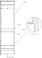
- FIG 10A shows a partial cross-sectional view of one example of the treatment valve assembly in the closed position detailing the Lubricated Region.
- a Lubricated Region 1001 is an annular region defined by the exterior surface of Inner Sleeve 201 and the interior surface of Ported Top Sub 101, between the Treatment Port Seal Assembly shown in Figure 10A and the Upper Chamber Seal Assembly shown in Figure 10B .
- Figure 10B shows a cross-sectional detail-view of one example of the Treatment Port Seal Assembly.
- Figure 10B is a detail view of the Treatment Port Seal Assembly, which, in this example, is identical to Figure 2B , and is included here to describe the upper boundary of Lubricated Region 1001.
- Figure 10C shows a cross-sectional detail-view of one example of the Upper Chamber Seal Assembly.
- Figure 10C is a detail view of the Upper Chamber Seal Assembly, which, in this example, is identical to Figure 2C , and is included here to describe the lower boundary of Lubricated Region 1001.
- Figure 10D shows a cross-sectional detail-view of one example of the Upper Lubrication Groove.
- an Upper Lubrication Groove 1002 is placed radially around the inside diameter of Ported Top Sub 101 and is located longitudinally below the Treatment Port Seal Assembly as shown in Figure 10B , and longitudinally above Treatment Port 208.
- Upper Lubrication Groove 1002 provides a low resistance channel for a lubricant that is to be introduced around the entire circumference of the Inner Sleeve.
- the lubricant is grease that does not cause damage to the formation or interact in the treatment fluid in a manner that causes a change to the fluid properties that would prevent a successful treatment.
- the lubricant is introduced to the lubrication groove, and subsequently the valve, through one or more of Lubrication Ports 105.
- the port is sealed with a cap or plug.
- the lubricant is formulated to operate as a debris barrier. An added benefit of the lubrication acting as a barrier is that it prevents debris from entering this area of Treatment Valve 100 and, when used in conjunction with Treatment Port Cover 402, ensures that the lubricant remains in place and fully prevents large debris from fouling Treatment Valve 100.
- Figure 10E shows a cross-sectional detail-view of one example of the Lower Lubrication Groove.
- a Lower Lubrication Groove 1003 is placed radially around the inside diameter of Ported Top Sub 101 and is located longitudinally above the Upper Chamber Seal Assembly as shown in Figure 10C , and longitudinally below Treatment Port 208.
- the function of Lower Lubrication Groove 1003 is equivalent to that of Upper Lubrication Groove 1002, as described with Figure 10D .
- FIG 11A shows a 3-D perspective view of one example of a multi-cycle Collet used to lock and unlock the Treatment Valve, to and from the open position.
- a Multi-Cycle Collet 1101 is matched with a compatible Multi-Cycle Housing 1201, allowing Treatment Valve 100 to be placed selectively into the open and closed positions a number of times.
- Multi-Cycle Collet 1101 is a cylindrical component constructed to create individual Collet Fingers 1102 which, in one example, is comprised of sixteen individual Collet Fingers 1102.
- Multi-Cycle Collet 1101 is shaped, positioned, and arranged to allow it to slide through Multi-Cycle Housing 1201, which has a smaller inside diameter than the outside diameter of Multi-Cycle Collet 1101. This is accomplished by machining individual Collet Fingers 1102, which can be viewed as individual cantilevered beams that will deflect under load. This deflection allows Collet Finger 1102 to deflect inward and pass through a smaller diameter of Multi-Cycle Housing 1201 and spring back to the original outside diameter.
- an additional feature of Multi-Cycle Collet 110 is that its composition, shape, position, and arrangement of fingers are designed to support longitudinal loads once engaged in a suitable retaining groove.
- the length, width and thickness of Collet Finger 1102 are selected to match its operational requirements, as these parameters determine the stress induced in individual Collet Fingers 1102 when deflected inward while shifting the Treatment Valve 100.
- the combination of those characteristics and the yield strength of the material used to construct Multi-Cycle Collet 1101 are selected to ensure that Collet Finger 1102 is flexible enough to spring back after being compressed, which is to say that the stress due to the applied inward deflection does not exceed the yield strength of the material used to construct Multi-Cycle Collet 1101.
- Collet Finger 1102 is of substantial enough strength to withstand the longitudinal loads applied during operation.
- Figure 11B shows a Cross-sectional view of one example of the multi-cycle Collet.
- a Collet Thread 1103 is used to fix Multi-Cycle Collet 1101 to Inner Sleeve 201 (not shown).
- Figure 11C shows a cut-away partial 3-D perspective detail-view of, in one example, the multi-cycle Collet Head.
- a Multi-Cycle Collet Head 1104 is disposed on Multi-Cycle Collet 1101.
- a Lower Collet Compression Face 1105 is disposed on Multi-Cycle Collet Head 1104 and is used to compress the collet in the downward movement as Treatment Valve 100 is opened.
- an Upper Collet Compression Face 1106 is used to compress the collet in the upward movement as Treatment Valve 1302 (shown in figure 13C ) is closed.
- FIG 12A shows a cross-sectional view of one example of the treatment valve assembly Housing for multi-cycle use.
- a Multi-Cycle Housing Collet Relief Groove 1202 is a groove placed into the Multi-Cycle Housing 1201, which allows Multi-Cycle Collet Finger(s) 1102 (shown in Figure 11A ) to be in a non-stressed state while Treatment Valve 100, is in the closed position 200.
- the placement of Multi-Cycle Collet Head 1104 in Housing Collet Relief Groove is shown in Figure 13B .
- Multi-Cycle Housing Collet Compression Face 1203 which acts on Lower Multi-Cycle Collet Compression Face 1105 (shown in Figure 11C ) to bend Multi-Cycle Collet Finger(s) 1102 (shown in Figure 11A ) as Treatment Valve 100 is moved from the closed position 1301.
- Figure 12B shows a cross-sectional detail-view of one example of multi-cycle Housing Open Retaining Face.
- a Multi-Cycle Housing Open Retaining Face 1204 is matched to Upper Multi-Cycle Collet Compression Face 1106 (one example shown in Figure 11C ) to prevent Treatment Valve 100 from closing after actuation.
- the interaction of the two faces are further discussed using, and in the descriptions for, Figures 13C and 13D .
- Figure 13A shows a cross-sectional detail-view of one example of a multi-cycle treatment valve assembly with multi-cycle components in the shouldered position.
- a Treatment Valve 100 is shown in the shouldered position with Multi-Cycle components 1301.
- this position is equivalent as that shown in Figure 8A with Collet 202 replaced with Multi-Cycle Collet 1101 and Housing member 102 replaced with Multi-Cycle Housing 1201.
- FIG. 13B shows a cross-sectional detail-view of one example of the Multi-Cycle Collet Head positioned in the Multi-Cycle Housing Collet Relief Groove.
- Multi-Cycle Collet 1101 is shown in relation to Bottom Sub 103 and Multi-Cycle Housing 1201 with Treatment Valve 100 in position 1301.
- a Multi-Cycle Collet Bottom Sub Gap 1303 is a standoff between the two components that prevent Multi-Cycle Collet Fingers 1102 from being loaded in compression, preventing, in one example, possible damage to Multi-Cycle Collet Fingers 1102.
- Multi-Cycle Housing Retaining Face 1204 and Multi-Cycle Collet Upper Compression Face 1106 are oriented at 60 degrees.
- Figure 13C shows a cross-sectional detail-view of one example of a multi-cycle treatment valve assembly with multi-cycle components in the open and locked position.
- Treatment Valve 100 is in the open position with Multi-Cycle components 1302. This position is equivalent as that shown in Figure 8C with Collet 202 replaced with Multi-Cycle Collet 1101 and Housing member 102 replaced with Multi-Cycle Housing 1201.
- FIG. 13D shows a cross-sectional detail-view of one example of the Multi-Cycle Collet Upper Compression Face engaged with the Multi-Cycle Housing Retaining Face.
- Multi-Cycle Collet 1101 is shown in relation to Multi-Cycle Housing 1201, with the Treatment Valve 100 in position 1302.
- Upper Multi-Cycle Collet Compression Face 1106 is shown in contact with Multi-Cycle Housing Retaining Face 1204. In this position, any further upward movement of Inner Sleeve 201 requires force sufficient to compress Multi-Cycle Collet 1101.
- the angle of Upper Multi-Cycle Collet Compression Face 1106 and Multi-Cycle Housing Retaining Face 1204, along with the composition, thickness, width and length of Multi-Cycle Collet Finger(s) 1102, determine the force required to compress Multi-Cycle Collet 1101, allowing movement of Inner Sleeve 201 to close Treatment Valve 100.
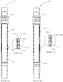
- Figure 14A shows a cross-sectional view of one example of the treatment valve assembly configured to use locking pins.
- a Locking Pin Treatment Valve in the closed position 1400 is shown as is an alternate example of Treatment Valve 100.
- one or more Locking Pins 1601 and one or more Locking Pin Spring Stacks 1603 are used to replace the function of Collet 202.
- major components of Locking Pin Treatment Valve 1400 include: a Locking Pin Ported Top Sub 1401, a Locking Pin Bottom Sub 1402, and a Locking Pin Inner Sleeve 1403.
- Locking Pin Ported Top Sub 1401 and Locking Pin Bottom Sub 1402 form the tool body.
- Locking Pin Top Sub 1401 and Locking Pin Bottom Sub 1402 are secured together with a threaded connection.
- Locking Pin Treatment Valve 1400 is deployed into a wellbore by placing it in-line with a production string. In one example, this is done by threading Locking Pin Bottom Sub 1402 of the assembled Locking Pin Treatment Valve 1400 into the production string as it is deployed into the wellbore, then threading the production string into Locking Pin Ported Top Sub 1401, and continuing to deploy the production string into the wellbore.
- a Locking Pin Inner Sleeve 1403 is radially disposed inside Treatment Valve 1400 and held in place by Shear Screw(s) 1404 which are inserted through Locking Pin Ported Top Sub 1401. Shear Screw(s) 1404 are used to maintain the position of Locking Pin Inner Sleeve 1403 until Locking Pin Treatment Valve 1400 is opened.
- Lubrication Ports/Plugs (in one example, similar to those shown in Figure 1 ) are used to provide lubrication to the actuating parts of Locking Pin Treatment Valve 1400 to increase the reliability of the assembly.
- the Lubrication Ports/Plugs are located and functionally equivalent to Lubrication Ports/Plugs 105, as described in Figures 10A, 10D and 10E .
- Locking Pin Inner Sleeve 1403 runs the length of Locking Pin Treatment Valve 1400, from the Treatment Port Seal Assembly as shown in Figure 14B , to the Lower Chamber Seal Assembly as shown in Figure 14D .
- the Locking Pin Inner Sleeve 1403 serves two functions in this position. First, it isolates the inside of Treatment Valve 1400 from the outside of the Treatment Valve 1400 by isolating Treatment Port 1405. Second, it is the inner member that forms the inner wall of Locking Chamber 1499.
- Locking Chamber 1499 is equivalent in function and location as Locking Chamber 299, which is described in detail in Figures 2A, 2B, 2C, 2D and 2E .
- another Oring Seal 1702 is used on Retaining Screw 1701 to seal Locking Chamber 1499.
- Figure 14B shows a cross-sectional detail-view of one example of the Treatment Port Seal Assembly.
- Figure 14B shows an example of the Treatment Port Seal Assembly, which is equivalent in function and location to the Treatment Port Seal Assembly shown and described in Figure 2B .
- Figure 14C shows a cross-sectional detail-view of one example of the Upper Chamber Seal Assembly.
- Figure 14C shows an example of the Upper Chamber Seal Assembly, which is equivalent in function and location to the Upper Chamber Seal Assembly shown and described in Figure 2C .
- Figure 14D shows a cross-sectional detail-view of one example of the Lower Chamber Seal Assembly.
- Figure 14D shows the Lower Chamber Seal Assembly, which is equivalent in function and location to the Lower Chamber Seal Assembly shown and described in Figure 2D .
- Figure 14E shows a cross-sectional detail-view of one example of the Locking Pin Mechanism.
- Figure 14E is a detailed view of the locking mechanism employed in Locking Pin Treatment Valve 1400. The individual components and operation of the locking mechanism are described in detail in Figures 15 , 16 , 17 and 18 .
- Figure 15A shows a 3-D perspective external view of one example of the Locking Pin Inner Sleeve.
- Figure 15A is an overall view of Locking Pin Inner Sleeve 1403, which is used to isolate Locking Pin Treatment Ports 1404, and embodies features to retain Locking Pin Inner Sleeve 1403 in various positions during operation.
- Figure 15B shows a cross-sectional view of one example of the Locking Pin Inner Sleeve.
- Figure 15B is a cross-sectional view of Locking Pin Inner Sleeve 1403 and shows the details of features used to maintain the longitudinal position of Locking Pin Inner Sleeve 1403 in the various desired positions.
- a Locking Pin Shear Screw Groove 1501 is located near the top of Locking Pin Inner Sleeve 1403 and is located such that Shear Screw(s) 1404, inserted through Locking Pin Ported Top Sub 1401, can engage the groove.
- a Locking Groove 1502 is located longitudinally below Locking Pin Shear Screw Groove 1501 and is used to engage Locking Pin 1601 (as detailed in one example in Figures 17A and 17B ).
- a Locking Pin Running Surface 1503 is located longitudinally below Locking Pin Groove 1502 and is the surface that Locking Pin 1601 rides on while Locking Pin Treatment Valve is moved from the closed position 1400 to the open and locked position 1800.
- a Locking Pin Inner Sleeve Landing Shoulder 1504 is equivalent in function and location to Inner Sleeve Landing Shoulder 604.
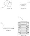
- Figure 16A shows a 3-D perspective external view of one example of the Locking Pin.
- a Locking Pin 1601 is used to engage Locking Pin Groove 1502.
- Locking Pin 1601 is a cylindrical member. The functionality of the Locking Pin in the overall locking mechanism are further discussed using, and in the descriptions for, Figures 17B and 18B .
- FIG 16B shows a 3-D perspective external view of one example of the Belleville Disc Spring.
- a Belleville Disc Spring is used for Locking Spring 1602.
- a Belleville Disc Spring is a specially formed washer that deflects when loaded in compression, much like a typical compression spring.
- Belleville Disc Springs typically provide spring constants larger than those attainable with wire wrapped springs of the same diameter.
- Another advantage of Belleville Disc Springs is that they can be stacked in a variety of combinations to yield the desired deflection, or an increase in working load, or a combination of the two.
- One example of stacking is further discussed using, and in the description for, Figure 16D .
- Figure 16C shows a cross-sectional view of one example of the Belleville Disc Spring.
- Figure 16C shows one example of the formed shape of Locking Spring 1602.
- Locking Spring 1602 is composed, shaped, positioned and arranged to deflect downward and have a subsequent reduction in height when subjected to a compressive force.
- Figure 16D shows a cross-sectional view of one example of the Locking Spring Stack.
- Locking Spring Stack 1603 is comprised of two or more Locking Springs 1602, deployed as part of the locking mechanism for Locking Pin Treatment Valve 1400.
- the stack arrangement is a series stack, meaning that each individual spring is stacked in an alternating orientation.
- a series stack is used to retain the working load of a single Belleville Disc Spring, or equivalent, while increasing the working deflection.
- a parallel stack is formed by arrangement where individual springs are stacked in the same orientation, retaining the working deflection of a single Belleville Disc Spring, or equivalent, while increasing the working load.
- a parallel-series combination stack is deployed, having a combination of individual springs, some stacked in parallel and some in stacked in series, resulting in both a working load and working deflection larger than a single Belleville Disc Spring, or equivalent.
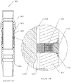
- Figure 17A shows a cross-sectional view of one example of the treatment valve assembly configured to use locking pins, shown in the closed position.
- Figure 17A is a cross-sectional view of the Locking Pin Treatment Valve in the closed position 1400 and is included to provide the location of the Locking Pin Mechanism, as shown in Figure 17B , while the Locking Pin Treatment Valve is closed.
- Figure 17B shows a cross-sectional detail-view of one example of the Locking Mechanism in the closed position.
- Figure 17B is a detail view of the Locking Pin Mechanism.
- the Locking Pin 1601 and Locking Spring Stack 1603 are radially disposed of in the Locking Pin Ported Top Sub 1401 and retained in place with a Retaining Screw 1701.
- An Oring Seal 1702 is radially disposed on Retaining Screw 1701 to seal Locking Chamber 1499.
- the Locking Pin 1601 is in contact with the Locking Pin Running Surface 1503 of Locking Pin Inner Sleeve 1403 and Locking Spring Stack 1603 is compressed.
- Locking Pin Inner Sleeve 1403 will shift downward and Locking Pin(s) 1601 will ride on Locking Pin Running Surface 1503.
- Figure 18A shows a cross-sectional view of one example of the treatment valve assembly configured to use locking pins, shown in the open and locked position.
- Figure 18A is a cross-sectional view of the Locking Pin Treatment Valve in the open and locked position 1800 and is included to provide the location of the Locking Pin Mechanism, as shown in Figure 18B , and the shouldering features in Figure 18C , while the Locking Pin Treatment Valve is closed.
- Figure 18B shows a cross-sectional detail-view of one example of the Locking Mechanism in the open and locked position 1800.
- Locking Pin 1601 is engaged in Locking Groove 1502 of Locking Pin Inner Sleeve 1403.
- Locking Spring Stack 1603 is shown in an extended state, which forces Locking Pin 1601 into Locking Groove 1503.
- Locking Pin 1601 is engaged in both Locking Pin Ported Top Sub 1401 and Locking Groove 1503, which prevents further movement of Locking Pin Inner Sleeve 1403, thus retaining the Locking Pin Treatment Valve in the open and locked position 1800.
- Figure 18C is a detailed view that shows the shouldering of the Locking Pin Inner Sleeve, 1403, in the Locking Pin Bottom Sub, 1402. The engagement occurs at the Locking Pin Inner Sleeve Shouldering Face 1504 and the Locking Pin Bottom Sub Shouldering Face 1801. The interaction of these two faces achieve the open and locked position 1800 of the Locking Pin Treatment Valve 1400.
- Figure 18C shows a cross-sectional detail-view of one example of a shoulder stop surface, shouldering Locking Pin Inner Sleeve 1403 in Locking Pin Bottom Sub 1402.
- the contact engagement occurs at Locking Pin Inner Sleeve Shouldering Face 1504 and Locking Pin Bottom Sub Shouldering 1801.
- the interaction of the two faces control the longitudinal positioning of Locking Pin Inner Sleeve 1403, preventing any downward loading of Locking Pin(s) 1601.
- the shouldered faces are placed at 60 degree angles.
- Figure 19 shows a flowchart describing examples of the method of operation of the Treatment Valve.
- the treatment valve assembly is assembled, in one example, in a shop (step 1901), and then deployed it in a wellbore, in one example, using a production string (step 1902).
- the treatment valve assembly is run in the wellbore with an activation tool (step 1903).
- the activation tool is a service packer.
- a service packer is deployed and set in the Treatment Valve 100.
- the service packer is deployed with Coiled Tubing.
- the service packer is deployed with jointed pipe.
- Treatment Valve 100 is first located by using Locator Groove 211 or equivalent marker (step 1904).
- Treatment Valve 100 is shifted open (step 1905) and the treatment placed (steps 1906, 1907).
- a dissolving fluid is placed across Treatment Valve 100 and forced through Treatment Port Cover 402 (steps 1908, 1909), and then the treatment is placed (step 1907).
- the service packer is unset (step 1910). If there are more Treatment Valves 100 to be utilized, the process is started again at locating the Treatment Valve 100 (step 1904). If there are no more Treatment Valves 100 to be utilized, the service packer is pulled out of hole (step 1911).
Landscapes
- Engineering & Computer Science (AREA)
- Geology (AREA)
- Life Sciences & Earth Sciences (AREA)
- Mining & Mineral Resources (AREA)
- Environmental & Geological Engineering (AREA)
- Fluid Mechanics (AREA)
- Physics & Mathematics (AREA)
- General Life Sciences & Earth Sciences (AREA)
- Geochemistry & Mineralogy (AREA)
- Surgical Instruments (AREA)
- Gasket Seals (AREA)
- Valve Housings (AREA)
- Drilling And Boring (AREA)
- Auxiliary Devices For Machine Tools (AREA)
- Infusion, Injection, And Reservoir Apparatuses (AREA)
Description
- The invention generally relates to tools for treatment of well-bores that are used, for example, in the exploration and production of oil and gas. Precisely the present invention is related to a system for selectively treating zones in a cased well-bore, the system comprising: a downhole, having a body, an inner bore therethrough, an inner surface of the body formed by the inner bore, and an outer surface; at least one treatment port disposed on the outer surface of the body; means for selectively isolating the inner bore from the outer surface, the means for selectively isolating the inner bore comprising a sliding sleeve disposed within the inner bore of the body; an annular chamber between the inner surface of the body and an outer surface of the sliding inner sleeve; means for maintaining the inner sliding sleeve in an open position, the means for maintaining disposed within the annular chamber; and means for maintaining the inner sliding sleeve in a closed position.
- Such a system is known from
US 2011/308817 A1 pertaining to a ported housing that may be connected along a casing string and the method for use of the ported housing in fracturing and/or treating multiple zones in a well. A sleeve is connected to the ported housing and may be moved between an initial position that prevents fluid flow through the ports of the housing and second position that permits fluid flow through the ports. A bottom hole assembly may be connected to the sleeve by an anchor. A packer element may create a seal between the bottom hole assembly and the sleeve permitting a pressure differential across the packer element to move bottom hole assembly down the casing moving the sleeve to the second position. In the second position, the formation adjacent to the ported housing may be stimulated and/or treated. - The system of the present invention is characterized by means for isolating, the means comprising the annular chamber, and by the chamber in isolation from the inner bore and the outer surface.
- Further improvements are subject to the dependent claims.
- In the following, preferred embodiments of the invention are depicted with reference to the accompanying Figures, in which:
-
Figure 1 shows a 3-D perspective external view of the treatment valve assembly incorporating one example of the present invention; -
Figure 2A shows a cross-sectional view of the treatment valve assembly incorporating one example of the present invention in the closed valve position; -
Figure 2B shows a cross-sectional detail-view of the Treatment Port Seal Assembly; -
Figure 2C shows a cross-sectional detail-view of the Upper Chamber Seal Assembly; -
Figure 2D shows a cross-sectional detail-view of the Lower Chamber Seal Assembly; -
Figure 2E shows a cross-sectional detail-view of the Shear Screw in Housing; -
Figure 3 shows a cross-sectional view of the treatment valve assembly incorporating one example of the present invention in the open and locked position; -
Figure 4A shows a cut-away partial 3-D perspective view of, in one example, the exterior of the treatment valve assembly, detailing the Treatment Port, Treatment Port Recess and Treatment Port Cover prior to placement; -
Figure 4B shows a cut-away partial 3-D perspective view of, in one example, the exterior of the treatment valve assembly, detailing the Treatment Port Cover installed in the Treatment Port Recess, over the Treatment Valve; -
Figure 5A shows a 3-D perspective view of one example of the Collet used to lock the Treatment Valve, in the open position; -
Figure 5B shows a Cross-sectional view of one example of the Collet; -
Figure 5C shows a cut-away partial 3-D perspective detail-view of, in one example, the Collet Head; -
Figure 6A shows a 3-D perspective external view of one example of the Collet installed on the Inner Sleeve; -
Figure 6B shows a cross-sectional view of one example of the Collet installed on the Inner Sleeve; -
Figure 6C shows a cross-sectional detail-view of one example of threads affixing the Collet to the Inner Sleeve; -
Figure 6D shows a cross-sectional detail-view of one example of the Collet Head positioned over an Inner Sleeve Collet Relief Groove; -
Figure 6E - shows a cross-sectional detail-view of one example of the Inner Sleeve Landing Surface; -
Figure 7A shows a cross-sectional view of one example of the treatment assembly Housing member; -
Figure 7B shows a cross-sectional detail-view of one example of the Housing Locking Face; -
Figure 8A shows a cross-sectional view of one example of the treatment valve assembly in the closed position; -
Figure 8B shows a cross-sectional detail-view of one example of the Collet Head positioned in the Housing Collet Relief Groove; -
Figure 8C shows a cross-sectional view of one example of the treatment valve assembly in the open and locked position; -
Figure 8D shows a cross-sectional detail-view of one example of the Collet Head positioned with the Collet Locking Face engaged with the Housing Locking Face; -
Figure 9A shows a cross-sectional view of one example of the treatment valve assembly in the shouldered position; -
Figure 9B shows a cross-sectional detail-view of one example of the Collet Head positioned in the Housing in the shouldered position; -
Figure 9C shows a cross-sectional detail-view of one example of the Inner Sleeve Landing surface urged onto the Bottom Sub Landing Surface in the shouldered position; -
Figure 10A shows a partial cross-sectional view of one example of the treatment valve assembly in the closed position detailing the Lubricated Region; -
Figure 10B shows a cross-sectional detail-view of one example of the Treatment Port Seal Assembly; -
Figure 10C shows a cross-sectional detail-view of one example of the Upper Chamber Seal Assembly; -
Figure 10D shows a cross-sectional detail-view of one example of the Upper Lubrication Groove; -
Figure 10E shows a cross-sectional detail-view of one example of the Lower Lubrication Groove; -
Figure 11A shows a 3-D perspective view of one example of a multi-cycle Collet used to lock and unlock the Treatment Valve, to and from the open position; -
Figure 11B shows a Cross-sectional view of one example of the multi-cycle Collet; -
Figure 11C shows a cut-away partial 3-D perspective detail-view of, in one example, the multi-cycle Collet Head; -
Figure 12A shows a cross-sectional view of one example of the treatment valve assembly Housing for multi-cycle use; -
Figure 12B shows a cross-sectional detail-view of one example of multi-cycle Housing Open Retaining Face; -
Figure 13A shows a cross-sectional detail-view of one example of a multi-cycle treatment valve assembly with multi-cycle components in the shouldered position; -
Figure 13B shows a cross-sectional detail-view of one example of the Multi-Cycle Collet Head positioned in the Multi-Cycle Housing Collet Relief Groove; -
Figure 13C shows a cross-sectional detail-view of one example of a multi-cycle treatment valve assembly with multi-cycle components in the open and locked position; -
Figure 13D shows a cross-sectional detail-view of one example of the Multi-Cycle Collet Upper Compression Face engaged with the Multi-Cycle Housing Retaining Face; -
Figure 14A shows a cross-sectional view of one example of the treatment valve assembly configured to use locking pins; -
Figure 14B shows a cross-sectional detail-view of one example of the Treatment Port Seal Assembly; -
Figure 14C shows a cross-sectional detail-view of one example of the Upper Chamber Seal Assembly; -
Figure 14D shows a cross-sectional detail-view of one example of the Lower Chamber Seal Assembly; -
Figure 14E shows a cross-sectional detail-view of one example of the Locking Pin Mechanism; -
Figure 15A shows a 3-D perspective external view of one example of the Locking Pin Inner Sleeve; -
Figure 15B shows a cross-sectional view of one example of the Locking Pin Inner Sleeve; -
Figure 16A shows a 3-D perspective external view of one example of the Locking Pin; -
Figure 16B shows a 3-D perspective external view of one example of the Belleville Disc Spring; -
Figure 16C shows a cross-sectional view of one example of the Belleville Disc Spring; -
Figure 16D shows a cross-sectional view of one example of the Locking Spring Stack; -
Figure 17A shows a cross-sectional view of one example of the treatment valve assembly configured to use locking pins, shown in the closed position; -
Figure 17B shows a cross-sectional detail-view of one example of the Locking Mechanism in the closed position; -
Figure 18A shows a cross-sectional view of one example of the treatment valve assembly configured to use locking pins, shown in the open and locked position; -
Figure 18B shows a cross-sectional detail-view of one example of the Locking Mechanism in the open and locked position; -
Figure 18C shows a cross-sectional detail-view of one example of a shoulder stop surface, shouldering Locking Pin Inner Sleeve in Locking Pin Bottom Sub; -
Figure 19 shows a flowchart describing an example of the method of operation of the Treatment Valve. -
Figure 1 shows a 3-D perspective external view of the treatment valve assembly incorporating one example of the present invention.Figure 1 is an external view of theTreatment Valve 100, and shows, in one example, its three major external components. APorted Top Sub 101 is attached to aBottom Sub 103 by aHousing member 102. In this example, these components form the tool body. In one example, these parts making up the body of the tool are secured together with threaded connections.Treatment Valve 100 is deployed into the wellbore by placing it in-line with a production string. In one example, this is done by threadingBottom Sub 103 of assembledTreatment Valve 100 into the production string as it is deployed into the wellbore, then threading the production string intoPorted Top Sub 101, and continuing to deploy the production string into the wellbore. - An Inner Sleeve 201 (as shown in
Figure 2A ) is radially disposed insideTreatment Valve 100 and held in place byShear Screws 104 which are inserted through and secured toHousing member 102. Shear Screws 104 are used to maintain the position ofInner Sleeve 201 untilTreatment Valve 100 is opened. Treatment Port(s) 208 are used to communicate fluids from the inside of theTreatment Valve 100 to the outside, similar in function to perforations that are placed in production strings with explosive charges. In one example, Treatment Port(s) 208 are oval in shape, and in that example the length and width of theTreatment Port 208 determine the flow area and velocity profile of the treatment fluid placed through the Treatment Port(s) 208. In one example, the size and shape of Treatment Port(s) 208 and the number ofTreatment Ports 208 are selected to optimize the placement of the treatment fluid into the formation(s). Each formation encountered has unique properties, which may require the size and shape of the Treatment Port(s) 208 to be adjusted to facilitate placing the desired treatment. In one example, Lubrication Ports/Plugs 105 are used to provide lubrication to the actuating parts of the Treatment Valve to increase the reliability of the assembly. -
Figure 2A shows a cross-sectional view of the treatment valve assembly incorporating one example of the present invention in the closed valve position.Figure 2A is a cross-sectional view of the assembledTreatment Valve 100 in the closed position (denoted as Treatment Valve 200), as it is run into the wellbore. AnInner Sleeve 201, runs the length of theTreatment Valve 200 from the Treatment Port Seal Assembly as shown inFigure 2B , to the Lower Chamber Seal Assembly as shown inFigure 2D . In one example,Inner Sleeve 201 serves two functions in this position. First, it isolates the inside ofTreatment Valve 200 from the outside of theTreatment Valve 200 by isolatingTreatment Port 208. Second, it is the inner member that forms the inner wall of the Locking Chamber, 299. ACollet 202 is radially disposed on the outside of theInner Sleeve 201 and, in one example, is used to maintain the Treatment Valve in the open position. Examples ofCollet 202, and its function are further detailed inFigures 5A-C ,6A-E ,8A-D ,9A-D .Orings 203 are placed to seal the threaded connection at thePorted Top Sub 101 andHousing 102 and the threaded connection atHousing 102 andBottom Sub 103. In one example, aLocator Groove 211 is placed radially inward inBottom Sub 103, located longitudinally near the bottom of the sub, and, in one example, is used to provide a means of locating the sleeve. A mechanical collar locator is known in the art as a means of locating upsets in wellbore tubulars, and can be used to locate the treatment valve assembly (the tool) by catching inLocator Groove 211. -
Figure 2B shows a cross-sectional detail-view of the Treatment Port Seal Assembly.Figure 2B shows the Treatment Port Seal Assembly which is radially disposed of inwardly inPorted Top Sub 101, located longitudinally above theTreatment Port 208 and is comprised of an Energizing Ring, 204 and a Seal Ring 205 which seals onInner Sleeve 201. In one example,Energizer Ring 204 is a Viton oring and Seal Ring 205 is a carbon filled Teflon ring. This seal assembly is capable of holding pressure in both directions, which is to say that it will maintain the isolation of the inside and outside of theTreatment Valve 100, regardless of which pressure is higher. In one example, Seal Ring 205 seals on the outside diameter ofInner Sleeve 201 and is well-suited for this application because it will not roll or be pulled out of the seal groove when pressure is applied and whenInner Sleeve 201 is shifted downward. In one example, Seal Ring 205 provides the required seal by being forced ontoInner Sleeve 201. Due to practical limitations in machining,Energizer Ring 204 is used to provide the force to engage the seal properly. In typical oring seals, the oring is compressed, which forces it onto the two parts being sealed; however, typical oring seals are known to roll in the groove and/or pull out of the groove when a part is moved under pressure. In a preferred embodiment, two individual seals, Seal Ring 205 andEnergizer Ring 204, combine into the seal assembly (shown inFigure 2B ) to yield a seal that is much better suited to the application of theTreatment Valve 100. -
Figure 2C shows a cross-sectional detail-view of the Upper Chamber Seal Assembly.Figure 2C shows the Upper Chamber Seal Assembly which is radially disposed of inwardly with the open face of the seal oriented upward inPorted Top Sub 101, located longitudinally below theTreatment Port 208, and is comprised of aLip Seal 206 and a Backup Ring, 207. In one example,Lip Seal 206 is a Viton seal andBackup Ring 207 is a Moly Glass Teflon Ring. In one example,Lip Seal 206 seals onInner Sleeve 201 and is capable of holding pressure in only one direction. In examples, lip seals are available in a variety of configurations and offered under a variety of commercial names, such as, lip seals and U cup seals. A predominate, defining characteristic of this type of seal is an open face elastomeric feature that is oriented towards the applied pressure. In examples, an energizer is placed in the open face to force the lip onto the part being sealed. Example energizers include springs, orings and X rings.Backup Ring 207 is placed on the low pressure side of the seal, and, in one example, is used to provide additional support toLip Seal 206, increasing the working pressure of the seal. Elastomeric seals are susceptible to extrusion, which is to say they push out into the gap between the parts being sealed. A seal will not hold the applied pressure and/or will interfere with the movement of the parts of the assembly when the seal extrudes through a gap to a point where it no longer is compressed onto the parts or is pulled out of the seal groove when the sealing parts are moved. Implementing a backup ring, forexample Backup Ring 207, provides additional support for the elastomeric seal by limiting the gap between the parts being sealed. In one preferred example, the lip seal configuration is particularly suited for this application because it is a pressure energized design, meaning that applied pressure to the open face acts to further engageLip Seal 206 onInner Sleeve 201. In this example, a primary function of the seal is to isolateLocking Chamber 299 from the external wellbore pressure on the outside ofTreatment Valve 100. -
Figure 2D shows a cross-sectional detail-view of the Lower Chamber Seal Assembly. In one example, the Lower Chamber Seal is radially disposed of inwardly with the open face of the seal oriented downward in theBottom Sub 103 and located longitudinally near the top of theBottom Sub 103 where it will engageInner Sleeve 201 whileTreatment Valve 100 is in theclosed position 200. In one example, the Lower Chamber Seal is comprised of the same components as the Upper Chamber Seal for the same functionality. -
Figure 2E shows a cross-sectional detail-view of the Shear Screw in Housing.Figure 2E showsShear Screw 104 engaged in bothHousing member 102 andInner Sleeve 201. In one example,Shear Screw 104 is placed radially on the exterior ofHousing member 102 and is located longitudinally near the top where it can engage aShear Screw Groove 601 of theInner Sleeve 201.Shear Screw 104 is used to maintainInner Sleeve 201 in the closed position until a predetermined downward force is applied toInner Sleeve 201, thus shearing the screws and allowing relative movement ofInner Sleeve 201 insideTreatment Valve 100. Shear Screw(s) 104 used, in one example, are self sealing. In one example, anOring Seal 210 is affixed toShear Screw 104, in a groove, and provides isolation in both directions. In one example,Oring Seal 210 in made of Viton. It is important to note that in one preferred example, the seal is maintained even after the screw itself is sheared during operation. - In one example,
Locking Chamber 299 is an annular region of the tool where features related to retainingTreatment Valve 100 in the desired closed and locked positions are located. In one example ofTreatment Valve 100, theLocking Chamber 299 is sealed from all wellbore fluids and associated debris to ensure that the locking features remain free of debris to enhance the reliability of operation. In one example,Locking Chamber 299 is constructed such that it is a constant-volume chamber, meaning that the volume of the chamber does not change when Treatment Valve 100 (inner sliding sleeve 201) is moved through its various positions. In one example,Locking Chamber 299 is defined by four major components:Ported Top Sub 101,Housing member 102,Bottom Sub 103, andInner Sleeve 201. The exterior surface ofInner Sleeve 201 defines an inner wall of the annular area and the combination of the interior surface walls ofPorted Top Sub 101,Housing member 102, andBottom Sub 103 define an outer wall of the annular area. The annular region is sealed on the up-hole end by the Upper Chamber Seal Assembly, as shown inFigure 2C , and theOring 203 at the threaded connection ofPorted Top Sub 101 andHousing member 102. The down-hole end ofLocking Chamber 299 is sealed by the Lower Chamber Seal, as shown inFigure 2D , and theother Oring 203 at the threaded connection ofHousing member 102 andBottom Sub 103. In one example, the final seal(s) isolatingLocking Chamber 299 include anOring Seal 210, located on Shear Screw(s) 104. - In one example of
Treatment Valve 100, this chamber is an atmospheric chamber, meaning that the pressure inLocking Chamber 299 is maintained at the atmospheric pressure when the tool was assembled. This can result in particularly high pressure differentials across the Upper and Lower Chamber Seals, as shown inFigures 2C and 2D . Consequently, the pressure energized design ofLip Seal 206 utilized in the Upper and Lower Chamber Seals, as shown inFigures 2C and 2D , is considered to greatly improve the overall reliability ofTreatment Valve 100. -
Figure 3 shows a cross-sectional view of the treatment valve assembly (the tool) incorporating one example of the present invention in the open and locked position. In one example, theFigure 3 cross-sectional view of the assembledTreatment Valve 100, in the open and lockedposition 300, is the final position ofTreatment Valve 100 after being actuated and the treatment placed. This position is attained by applying a downward force toInner Sleeve 201 which is sufficient to shear Shear Screw(s) 104. Once Shear Screw(s) 104 are sheared,Inner Sleeve 201 moves down and disengages the Treatment Port Seal Assembly, as shown inFigure 2B , exposingTreatment Ports 208.Treatment Ports 208 are exposed to provide fluid access to the reservoir behind the production string, and communicate the inside of the production string to the fluids in the reservoir. This communication enables both placing the treatment and producing the reservoir. -
Figure 4A shows a cut-away partial 3-D perspective view of, in one example, the exterior of the treatment valve assembly, detailing the Treatment Port, Treatment Port Recess and Treatment Port Cover prior to placement.Figure 4A shows a detailed view ofTreatment Port 208 andTreatment Port Cover 402, which is used to shieldTreatment port 208 from debris while being run in the wellbore and maintaining the lubrication of the valve. Also shown inFigure 2A is aTreatment Port Recess 401 in whichTreatment Port Cover 402 is placed. -
Figure 4B shows a cut-away partial 3-D perspective view of, in one example, the exterior of the treatment valve assembly (the tool), detailing the Treatment Port Cover installed in the Treatment Port Recess, over the Treatment Valve.Figure 4B showsTreatment Port Cover 402 placed inTreatment Port Recess 401. In one example,Treatment Port Cover 402 is adhered toTreatment Port Recess 401 by a suitable adhesive or solder. While being run in the wellbore,Treatment Valve 100 will be in contact with the wellbore or other tubular walls in both a sliding and rotating motion; therefore, in one example,Treatment Port Recess 401 is important because it protectsTreatment Port Cover 402 from being pulled offTreatment Valve 100 due to contact with the wellbore or other tubulars in which it is conveyed through. In one example, the treatment port cover thickness and material combination provide a limited strength that can be ruptured by applying pressure from fluids pumped from the inner bore. In a preferred example,Treatment Port Cover 402 is constructed from a material that is dissolvable by a fluid that is compatible with the formation. In one example, the dissolvable fluid is selected from those fluids that are capable of dissolving the cover and yet are non-damaging to the wellbore formation of interest. In one example, the dissolving fluid is 15% Hydrochloric Acid. In one example, the treatment port cover thickness and material combination provide a limited strength that can be ruptured, after applying the dissolving fluid, by applying pressure from fluids pumped from the inner bore. In one example,Treatment Port Cover 402 is constructed of aluminum and, in further example, is .007 inch thick with, in further example, two 1/16 inch holes placed on the centerline. In one example, the holes placed inTreatment Port Cover 402 facilitate contact of the dissolving fluid withTreatment Port Cover 402, in one example, by preventing a dead volume. In one example,Treatment Port Cover 402 is constructed, positioned, and arranged to keep debris out of the valve actuation area. In one example,Treatment Port Cover 402 is constructed, positioned, and arranged to maintain the lubrication placed inTreatment Valve 100, at surface, which is introduced through Lubrication Port/Plug(s) 105. -
Figure 5A shows a 3-D perspective view of one example of the Collet used to lock the Treatment Valve in the open position.Figure 5A is an overall view ofCollet 202 which is used to lockTreatment Valve 100 in theopen position 300. In one example,Collet 202 is a cylindrical component that is constructed to createindividual Collet Fingers 501 which, in one example, is comprised of sixteenindividual Collet Fingers 501, in one example, disposed in longitudinal orientation circumferentially about the axis of the collet. In one example,Collet 202 is a hollow cylindrical member. In one example,Collet 202 is a unitary cylindrical member.Collet 202 is shaped, positioned, and arranged to allow it to slide throughHousing member 102, which, in one example, has a smaller inside diameter than the outside diameter ofCollet 202. In one example, this is accomplished by machiningindividual Collet Fingers 501, which can be viewed as individual cantilevered beams that will deflect under load. This deflection allowsCollet Finger 501 to deflect inward and pass through a smaller diameter restriction ofHousing 102 and spring back to the original outside diameter past the restriction. In one example, an additional feature ofCollet 202 is that is can support longitudinal loads once engaged in a suitable retaining groove. - In one example, the length, width and thickness of
Collet Fingers 501 are selected to match its operational requirements, as these parameters determine the stress induced inindividual Collet Fingers 501 when deflected inward while shifting theTreatment Valve 100. The combination of those characteristics and the yield strength of the material used to constructCollet 202 are selected to ensure thatCollet Finger 501 is flexible enough to spring back after being compressed, which is to say that the stress due to the applied inward deflection does not exceed the yield strength of the material used to constructCollet 202. In one example,Collet Finger 501 is of substantial enough strength to withstand the longitudinal loads applied during operation. -
Figure 5B shows a Cross-sectional view of one example of the Collet.Figure 5B shows theCollet Thread 502, used to fix Collet, 202 toInner Sleeve 201 atInner Sleeve Thread 602. -
Figure 5C shows a cut-away partial 3-D perspective detail-view of, in one example, theCollet Head 503. ACollet Compression Face 504 is used to compress the collet in the downward movement by contactingHousing Compression Face 702. In one example,Compression Face 504 is a surface on the free end of the cantilevered beam (finger), the compression surface forming part of the head that protrudes radially outward relative to the axis of the collet.Collet Locking Face 505 is machined to match aHousing Locking Face 703 inHousing member 102, preventingTreatment Valve 100 from closing after being opened. In one example,Locking Face 505 is a surface on the free end of the cantilevered beam (finger), the locking surface forming part of the head that protrudes radially outward relative to the axis of the collet. In one example, the locking surface is disposed with a negative rake, for example, disposed at an angle less than 90 degrees from the longitudinal axis and in the direction of the first end of the beam, as illustrated infigure 5C . In one example,Collet Locking Face 505 has an angle of 30 degrees, for example, 30 degrees from the longitudinal axis and in the direction of the first end of the beam. In one example, to simplify machining,Collet Locking Face 505 has an angle of 35 degree, for example, 35 degrees from the longitudinal axis and in the direction of the first end of the beam. - In one example, the term collet refers to the physical appearance of the member, but does not necessarily require the collet member to squeeze the inner sleeve for secure holding. Rather, in one example, the collet member is secured to the inner sleeve by other means, such as threads, and the collet member functions to provide outwardly expanding fingers to urge stops, or locking faces, outward towards the inner surface wall of the assembly housing or body. The fingers are compressible radially inwards, allowing locking faces to be longitudinally inserted in position, longitudinally past diameter restrictions on the inner face of the assembly housing/body.
-
Figure 6A shows a 3-D perspective external view of one example of the Collet installed on the Inner Sleeve.Collet 202 is shown installed onInner Sleeve 201.Collet 202 is placed radially onInner Sleeve 201, longitudinally located on anInner Sleeve Thread 602, with Collet Head(s) 503 oriented downward fromThreads -
Figure 6B shows a cross-sectional view of one example of the installed on the Inner Sleeve.Collet 202 is shown installed onInner Sleeve 201. AShear Screw Groove 601 is a groove radially placed onInner Sleeve 201, placed longitudinally such that Shear Screws 104, inserted and retained inHousing 102, can be engaged. -
Figure 6C shows a cross-sectional detail-view of one example of threads affixing the Collet to the Inner Sleeve.Threads Collet 202 toInner Sleeve 201. -
Figure 6D shows a cross-sectional detail-view of one example of the Collet Head positioned over an Inner Sleeve Collet Relief Groove.Collet Head 503, as shown, is located onInner Sleeve 201. The Inner SleeveCollet Relief Groove 603 is a small relief placed on the exterior ofInner Sleeve 201 to allow for proper deflection ofCollet Head 503 as it is compressed while moving longitudinally throughHousing 102, such thatCollet Head 503 does not contactInner Sleeve 201 as theTreatment Valve 100 is moved from the closed position. -
Figure 6E - shows a cross-sectional detail-view of one example of the Inner Sleeve Landing Surface. An InnerSleeve Landing Surface 604 is shown onInner Sleeve 201, in one example, is used to limit the movement ofInner Sleeve 201 withinTreatment Valve 100. InnerSleeve Landing Surface 604 will come in contact with the BottomSub Landing Surface 901. In one example, InnerSleeve Landing Surface 604 forms a contact shoulder against BottomSub Landing Surface 901 to limit further longitudinal movement ofInner Sleeve 201. -
Figure 7A shows a cross-sectional view of one example of the treatment assembly Housing member.Housing member 102 is shown with detail of a HousingCollet Relief Groove 701, which is a groove placed intoHousing member 102, allowing Collet Finger(s) 501 (as shown inFigure 5A ) to be in a non-stressed state whileTreatment Valve 100 is in theclosed position 200. In one example, the placement ofCollet Head 503 in HousingCollet Relief Groove 701 is shown inFigure 8B . A HousingCollet Compression Face 702 is shown, which acts on Collet Compression Face 504 (as shown inFigure 5C ) to bend Collet Finger(s) 501 (not shown) as the Treatment Valve, 100, is moved from the closed position, 200. -
Figure 7B shows a cross-sectional detail-view of one example of the Housing Locking Face. AHousing Locking Face 703 is matched to Collet Locking Face 505 (shown inFigure 5C ) to preventTreatment Valve 100 from closing after actuation. The interaction of the two locking faces are further discussed usingFigures 8D and9B . -
Figure 8A shows a cross-sectional view of one example of the treatment valve assembly in the closed position.Treatment Valve 100 in theclosed position 200 is included to show the location ofCollet Head 502 relative to the treatment valve assembly in theclosed position 200. -
Figure 8B shows a cross-sectional detail-view of one example of the Collet Head positioned in the Housing Collet Relief Groove.Collet Head 503 is shown disposed in HousingCollet Relief Groove 701, whenTreatment Valve 100 is in the closed position, 200. This relief groove allows the Collet to be placed in the assembly without stressing the Collet Finger(s) 501. AsTreatment Valve 100 is moved from theclosed position 200,Collet Compression Face 504 contactsHousing Compression Face 702, forcing Collet Finger(s), 501 to deflect radially inward. -
Figure 8C shows a cross-sectional view of one example of the treatment valve assembly in the open and locked position.Treatment Valve 100, in the open and lockedposition 300, is included to show the location ofCollet Head 503 relative to the treatment valve assembly in the open and locked position, 300. -
Figure 8D shows a cross-sectional detail-view of one example of the Collet Head positioned with the Collet Locking Face engaged with the Housing Locking Face.Collet Head 503 is shown disposed inHousing member 102, when theTreatment Valve 100 is in the open and lockedposition 300.Collet Locking Face 505 is in contact withHousing Locking Face 703. These two faces are in contact and, in one example, the 30 degree angle at which they are placed in the assembly prevent theTreatment Valve 100 from closing. An upward force placed on theInner Sleeve 201 is transmitted to Collet 202 by the thread engagement atCollet Threads 502 andSeal Threads 602. This force is further transmitted throughCollet Finger 501, and then toHousing member 102 by the engagement ofCollet Locking Face 505 andHousing Locking Face 703, thus preventingTreatment Valve 100 from closing. The angle of the locking faces act to lockTreatment Valve 100 by preventing Collet Finger(s) 501 from deflecting inward when an upward force is applied toInner Sleeve 203. -
Figure 9A shows a cross-sectional view of one example of the treatment valve assembly in the shouldered position.Treatment Valve 100, in the shoulderedposition 900, is included to show the location ofCollet Head 503 relative to the treatment value assembly in the shoulderedposition 900. In one example, shoulderedposition 900 is defined by the contact ofInner Sleeve 201 andBottom Sub 103, which prevents any further movement in the downward direction. Shouldered is meant to describe an arrangement where the two parts are touching but are not locked together. -
Figure 9B shows a cross-sectional detail-view of one example of the Collet Head positioned in the Housing in the shouldered position.Collet Head 503 is shown disposed inHousing member 102 when theTreatment Valve 100 is in the shouldered position, 900. A Collet-Bottom Sub Gap 801 is formed by the space betweenCollet Head 503 andBottom Sub 103. The shoulderedposition 900 is achieved whenInner Sleeve 201 comes in contact withBottom Sub 103 and prevents further downward movement ofInner Sleeve 201 in Treatment Valve, 100. This position is important because, in one example, Collet Finger(s) 501 are slender items that cannot support significant longitudinal compression loading. If Collet Finger(s) 501 were to be loaded in compression longitudinally it is likely they would buckle and preventingCollet Locking Face 505 from engagingHousing Locking Face 703 and/or damage Collet Finger(s) 501, preventing them from being able to support an upward load applied toInner Sleeve 201. If either of these two conditions existed, theTreatment Valve 100 could close after opening. -
Figure 9C shows a cross-sectional detail-view of one example of the Inner Sleeve Landing surface urged onto the Bottom Sub Landing Surface in the shouldered position. In one example,Inner Sleeve 201 shoulders ontoBottom Sub 103. The engagement occurs at an InnerSleeve Shouldering Face 604 and a BottomSub Shouldering Face 901. The interaction of these two faces achieves the shoulderedposition 900 ofTreatment Valve 100 and prevents any compression loading and subsequent damage of Collet Finger(s) 501 (not shown). In one example, the shouldered faces are placed at 60 degree angles. -
Figure 10A shows a partial cross-sectional view of one example of the treatment valve assembly in the closed position detailing the Lubricated Region. In one example, aLubricated Region 1001 is an annular region defined by the exterior surface ofInner Sleeve 201 and the interior surface ofPorted Top Sub 101, between the Treatment Port Seal Assembly shown inFigure 10A and the Upper Chamber Seal Assembly shown inFigure 10B . -
Figure 10B shows a cross-sectional detail-view of one example of the Treatment Port Seal Assembly.Figure 10B is a detail view of the Treatment Port Seal Assembly, which, in this example, is identical toFigure 2B , and is included here to describe the upper boundary ofLubricated Region 1001. -
Figure 10C shows a cross-sectional detail-view of one example of the Upper Chamber Seal Assembly.Figure 10C is a detail view of the Upper Chamber Seal Assembly, which, in this example, is identical toFigure 2C , and is included here to describe the lower boundary ofLubricated Region 1001. -
Figure 10D shows a cross-sectional detail-view of one example of the Upper Lubrication Groove. In one example, anUpper Lubrication Groove 1002 is placed radially around the inside diameter ofPorted Top Sub 101 and is located longitudinally below the Treatment Port Seal Assembly as shown inFigure 10B , and longitudinally aboveTreatment Port 208. In one example,Upper Lubrication Groove 1002 provides a low resistance channel for a lubricant that is to be introduced around the entire circumference of the Inner Sleeve. In one example, the lubricant is grease that does not cause damage to the formation or interact in the treatment fluid in a manner that causes a change to the fluid properties that would prevent a successful treatment. In one example, the lubricant is introduced to the lubrication groove, and subsequently the valve, through one or more ofLubrication Ports 105. In one example, after the lubricant is introduced viaLubrication Port 105, the port is sealed with a cap or plug. In one example, the lubricant is formulated to operate as a debris barrier. An added benefit of the lubrication acting as a barrier is that it prevents debris from entering this area ofTreatment Valve 100 and, when used in conjunction withTreatment Port Cover 402, ensures that the lubricant remains in place and fully prevents large debris from foulingTreatment Valve 100. -
Figure 10E shows a cross-sectional detail-view of one example of the Lower Lubrication Groove. In one example, a Lower Lubrication Groove 1003 is placed radially around the inside diameter ofPorted Top Sub 101 and is located longitudinally above the Upper Chamber Seal Assembly as shown inFigure 10C , and longitudinally belowTreatment Port 208. In one example, the function of Lower Lubrication Groove 1003 is equivalent to that ofUpper Lubrication Groove 1002, as described withFigure 10D . -
Figure 11A shows a 3-D perspective view of one example of a multi-cycle Collet used to lock and unlock the Treatment Valve, to and from the open position. In one example, aMulti-Cycle Collet 1101 is matched with a compatibleMulti-Cycle Housing 1201, allowingTreatment Valve 100 to be placed selectively into the open and closed positions a number of times. In one example,Multi-Cycle Collet 1101 is a cylindrical component constructed to createindividual Collet Fingers 1102 which, in one example, is comprised of sixteenindividual Collet Fingers 1102. In one example,Multi-Cycle Collet 1101 is shaped, positioned, and arranged to allow it to slide throughMulti-Cycle Housing 1201, which has a smaller inside diameter than the outside diameter ofMulti-Cycle Collet 1101. This is accomplished by machiningindividual Collet Fingers 1102, which can be viewed as individual cantilevered beams that will deflect under load. This deflection allowsCollet Finger 1102 to deflect inward and pass through a smaller diameter ofMulti-Cycle Housing 1201 and spring back to the original outside diameter. In one example, an additional feature of Multi-Cycle Collet 110 is that its composition, shape, position, and arrangement of fingers are designed to support longitudinal loads once engaged in a suitable retaining groove. - In one example, the length, width and thickness of
Collet Finger 1102 are selected to match its operational requirements, as these parameters determine the stress induced inindividual Collet Fingers 1102 when deflected inward while shifting theTreatment Valve 100. The combination of those characteristics and the yield strength of the material used to constructMulti-Cycle Collet 1101 are selected to ensure thatCollet Finger 1102 is flexible enough to spring back after being compressed, which is to say that the stress due to the applied inward deflection does not exceed the yield strength of the material used to constructMulti-Cycle Collet 1101. In one example,Collet Finger 1102 is of substantial enough strength to withstand the longitudinal loads applied during operation. -
Figure 11B shows a Cross-sectional view of one example of the multi-cycle Collet. In one example, aCollet Thread 1103 is used to fixMulti-Cycle Collet 1101 to Inner Sleeve 201 (not shown). -
Figure 11C shows a cut-away partial 3-D perspective detail-view of, in one example, the multi-cycle Collet Head. AMulti-Cycle Collet Head 1104 is disposed onMulti-Cycle Collet 1101. In one example, a LowerCollet Compression Face 1105 is disposed onMulti-Cycle Collet Head 1104 and is used to compress the collet in the downward movement asTreatment Valve 100 is opened. In one example, an UpperCollet Compression Face 1106 is used to compress the collet in the upward movement as Treatment Valve 1302 (shown infigure 13C ) is closed. -
Figure 12A shows a cross-sectional view of one example of the treatment valve assembly Housing for multi-cycle use. In one example, a Multi-Cycle HousingCollet Relief Groove 1202 is a groove placed into theMulti-Cycle Housing 1201, which allows Multi-Cycle Collet Finger(s) 1102 (shown inFigure 11A ) to be in a non-stressed state whileTreatment Valve 100, is in theclosed position 200. The placement ofMulti-Cycle Collet Head 1104 in Housing Collet Relief Groove is shown inFigure 13B . Also shown is Multi-Cycle HousingCollet Compression Face 1203, which acts on Lower Multi-Cycle Collet Compression Face 1105 (shown inFigure 11C ) to bend Multi-Cycle Collet Finger(s) 1102 (shown inFigure 11A ) asTreatment Valve 100 is moved from theclosed position 1301. -
Figure 12B shows a cross-sectional detail-view of one example of multi-cycle Housing Open Retaining Face. In one example, a Multi-Cycle HousingOpen Retaining Face 1204 is matched to Upper Multi-Cycle Collet Compression Face 1106 (one example shown inFigure 11C ) to preventTreatment Valve 100 from closing after actuation. The interaction of the two faces are further discussed using, and in the descriptions for,Figures 13C and 13D . -
Figure 13A shows a cross-sectional detail-view of one example of a multi-cycle treatment valve assembly with multi-cycle components in the shouldered position. In one example, aTreatment Valve 100 is shown in the shouldered position withMulti-Cycle components 1301. In one example, this position is equivalent as that shown inFigure 8A withCollet 202 replaced withMulti-Cycle Collet 1101 andHousing member 102 replaced withMulti-Cycle Housing 1201. -
Figure 13B shows a cross-sectional detail-view of one example of the Multi-Cycle Collet Head positioned in the Multi-Cycle Housing Collet Relief Groove. In one example,Multi-Cycle Collet 1101 is shown in relation toBottom Sub 103 andMulti-Cycle Housing 1201 withTreatment Valve 100 inposition 1301. In one example, a Multi-Cycle ColletBottom Sub Gap 1303 is a standoff between the two components that preventMulti-Cycle Collet Fingers 1102 from being loaded in compression, preventing, in one example, possible damage toMulti-Cycle Collet Fingers 1102. Also shown are Upper Multi-CycleCollet Compression Face 1106 and Multi-CycleHousing Retaining Face 1204. In one example, Multi-CycleHousing Retaining Face 1204 and Multi-Cycle ColletUpper Compression Face 1106 are oriented at 60 degrees. -
Figure 13C shows a cross-sectional detail-view of one example of a multi-cycle treatment valve assembly with multi-cycle components in the open and locked position. In one example,Treatment Valve 100 is in the open position withMulti-Cycle components 1302. This position is equivalent as that shown inFigure 8C withCollet 202 replaced withMulti-Cycle Collet 1101 andHousing member 102 replaced withMulti-Cycle Housing 1201. -
Figure 13D shows a cross-sectional detail-view of one example of the Multi-Cycle Collet Upper Compression Face engaged with the Multi-Cycle Housing Retaining Face. In one example,Multi-Cycle Collet 1101 is shown in relation toMulti-Cycle Housing 1201, with theTreatment Valve 100 inposition 1302. Upper Multi-CycleCollet Compression Face 1106 is shown in contact with Multi-CycleHousing Retaining Face 1204. In this position, any further upward movement ofInner Sleeve 201 requires force sufficient to compressMulti-Cycle Collet 1101. In one example, the angle of Upper Multi-CycleCollet Compression Face 1106 and Multi-CycleHousing Retaining Face 1204, along with the composition, thickness, width and length of Multi-Cycle Collet Finger(s) 1102, determine the force required to compressMulti-Cycle Collet 1101, allowing movement ofInner Sleeve 201 to closeTreatment Valve 100. -
Figure 14A shows a cross-sectional view of one example of the treatment valve assembly configured to use locking pins. In one example, a Locking Pin Treatment Valve in theclosed position 1400, is shown as is an alternate example ofTreatment Valve 100. In one example, one ormore Locking Pins 1601 and one or more LockingPin Spring Stacks 1603 are used to replace the function ofCollet 202. In one example, major components of LockingPin Treatment Valve 1400 include: a Locking PinPorted Top Sub 1401, a LockingPin Bottom Sub 1402, and a LockingPin Inner Sleeve 1403. In this example, Locking PinPorted Top Sub 1401 and LockingPin Bottom Sub 1402 form the tool body. LockingPin Top Sub 1401 and LockingPin Bottom Sub 1402 are secured together with a threaded connection. In one example, LockingPin Treatment Valve 1400 is deployed into a wellbore by placing it in-line with a production string. In one example, this is done by threading LockingPin Bottom Sub 1402 of the assembled LockingPin Treatment Valve 1400 into the production string as it is deployed into the wellbore, then threading the production string into Locking PinPorted Top Sub 1401, and continuing to deploy the production string into the wellbore. - In one example, a Locking
Pin Inner Sleeve 1403 is radially disposed insideTreatment Valve 1400 and held in place by Shear Screw(s) 1404 which are inserted through Locking PinPorted Top Sub 1401. Shear Screw(s) 1404 are used to maintain the position of LockingPin Inner Sleeve 1403 until LockingPin Treatment Valve 1400 is opened. In one example, Lubrication Ports/Plugs (in one example, similar to those shown inFigure 1 ) are used to provide lubrication to the actuating parts of LockingPin Treatment Valve 1400 to increase the reliability of the assembly. In one example, the Lubrication Ports/Plugs are located and functionally equivalent to Lubrication Ports/Plugs 105, as described inFigures 10A, 10D and 10E . - In one example, Locking
Pin Inner Sleeve 1403 runs the length of LockingPin Treatment Valve 1400, from the Treatment Port Seal Assembly as shown inFigure 14B , to the Lower Chamber Seal Assembly as shown inFigure 14D . The LockingPin Inner Sleeve 1403 serves two functions in this position. First, it isolates the inside ofTreatment Valve 1400 from the outside of theTreatment Valve 1400 by isolatingTreatment Port 1405. Second, it is the inner member that forms the inner wall ofLocking Chamber 1499. In one example,Locking Chamber 1499 is equivalent in function and location asLocking Chamber 299, which is described in detail inFigures 2A, 2B, 2C, 2D and 2E . In one example, anotherOring Seal 1702 is used onRetaining Screw 1701 to sealLocking Chamber 1499. -
Figure 14B shows a cross-sectional detail-view of one example of the Treatment Port Seal Assembly.Figure 14B shows an example of the Treatment Port Seal Assembly, which is equivalent in function and location to the Treatment Port Seal Assembly shown and described inFigure 2B . -
Figure 14C shows a cross-sectional detail-view of one example of the Upper Chamber Seal Assembly.Figure 14C shows an example of the Upper Chamber Seal Assembly, which is equivalent in function and location to the Upper Chamber Seal Assembly shown and described inFigure 2C . -
Figure 14D shows a cross-sectional detail-view of one example of the Lower Chamber Seal Assembly.Figure 14D shows the Lower Chamber Seal Assembly, which is equivalent in function and location to the Lower Chamber Seal Assembly shown and described inFigure 2D . -
Figure 14E shows a cross-sectional detail-view of one example of the Locking Pin Mechanism.Figure 14E is a detailed view of the locking mechanism employed in LockingPin Treatment Valve 1400. The individual components and operation of the locking mechanism are described in detail inFigures 15 ,16 ,17 and18 . -
Figure 15A shows a 3-D perspective external view of one example of the Locking Pin Inner Sleeve.Figure 15A is an overall view of LockingPin Inner Sleeve 1403, which is used to isolate LockingPin Treatment Ports 1404, and embodies features to retain LockingPin Inner Sleeve 1403 in various positions during operation. -
Figure 15B shows a cross-sectional view of one example of the Locking Pin Inner Sleeve.Figure 15B is a cross-sectional view of LockingPin Inner Sleeve 1403 and shows the details of features used to maintain the longitudinal position of LockingPin Inner Sleeve 1403 in the various desired positions. A Locking PinShear Screw Groove 1501 is located near the top of LockingPin Inner Sleeve 1403 and is located such that Shear Screw(s) 1404, inserted through Locking PinPorted Top Sub 1401, can engage the groove. In one example, aLocking Groove 1502 is located longitudinally below Locking PinShear Screw Groove 1501 and is used to engage Locking Pin 1601 (as detailed in one example inFigures 17A and 17B ). In one example, a LockingPin Running Surface 1503 is located longitudinally belowLocking Pin Groove 1502 and is the surface thatLocking Pin 1601 rides on while Locking Pin Treatment Valve is moved from theclosed position 1400 to the open and lockedposition 1800. In one example, a Locking Pin InnerSleeve Landing Shoulder 1504 is equivalent in function and location to InnerSleeve Landing Shoulder 604. -
Figure 16A shows a 3-D perspective external view of one example of the Locking Pin. In one example, aLocking Pin 1601 is used to engageLocking Pin Groove 1502. In one example,Locking Pin 1601 is a cylindrical member. The functionality of the Locking Pin in the overall locking mechanism are further discussed using, and in the descriptions for,Figures 17B and18B . -
Figure 16B shows a 3-D perspective external view of one example of the Belleville Disc Spring. In one example, a Belleville Disc Spring is used forLocking Spring 1602. A Belleville Disc Spring is a specially formed washer that deflects when loaded in compression, much like a typical compression spring. One of the advantages of the design is that Belleville Disc Springs typically provide spring constants larger than those attainable with wire wrapped springs of the same diameter. Another advantage of Belleville Disc Springs is that they can be stacked in a variety of combinations to yield the desired deflection, or an increase in working load, or a combination of the two. One example of stacking is further discussed using, and in the description for,Figure 16D . -
Figure 16C shows a cross-sectional view of one example of the Belleville Disc Spring.Figure 16C shows one example of the formed shape ofLocking Spring 1602. In one example,Locking Spring 1602 is composed, shaped, positioned and arranged to deflect downward and have a subsequent reduction in height when subjected to a compressive force. -
Figure 16D shows a cross-sectional view of one example of the Locking Spring Stack.Locking Spring Stack 1603 is comprised of two ormore Locking Springs 1602, deployed as part of the locking mechanism for LockingPin Treatment Valve 1400. In one example, the stack arrangement is a series stack, meaning that each individual spring is stacked in an alternating orientation. A series stack is used to retain the working load of a single Belleville Disc Spring, or equivalent, while increasing the working deflection. In one example, a parallel stack is formed by arrangement where individual springs are stacked in the same orientation, retaining the working deflection of a single Belleville Disc Spring, or equivalent, while increasing the working load. In one example, a parallel-series combination stack is deployed, having a combination of individual springs, some stacked in parallel and some in stacked in series, resulting in both a working load and working deflection larger than a single Belleville Disc Spring, or equivalent. -
Figure 17A shows a cross-sectional view of one example of the treatment valve assembly configured to use locking pins, shown in the closed position.Figure 17A is a cross-sectional view of the Locking Pin Treatment Valve in theclosed position 1400 and is included to provide the location of the Locking Pin Mechanism, as shown inFigure 17B , while the Locking Pin Treatment Valve is closed. -
Figure 17B shows a cross-sectional detail-view of one example of the Locking Mechanism in the closed position.Figure 17B is a detail view of the Locking Pin Mechanism. TheLocking Pin 1601 andLocking Spring Stack 1603 are radially disposed of in the Locking PinPorted Top Sub 1401 and retained in place with aRetaining Screw 1701. AnOring Seal 1702 is radially disposed onRetaining Screw 1701 to sealLocking Chamber 1499. In theclosed position 1400, theLocking Pin 1601 is in contact with the LockingPin Running Surface 1503 of LockingPin Inner Sleeve 1403 andLocking Spring Stack 1603 is compressed. When a downward force is applied to LockingPin Inner Sleeve 1401, sufficient to break Shear Screws 1404, the LockingPin Inner Sleeve 1403 will shift downward and Locking Pin(s) 1601 will ride on LockingPin Running Surface 1503. -
Figure 18A shows a cross-sectional view of one example of the treatment valve assembly configured to use locking pins, shown in the open and locked position.Figure 18A is a cross-sectional view of the Locking Pin Treatment Valve in the open and lockedposition 1800 and is included to provide the location of the Locking Pin Mechanism, as shown inFigure 18B , and the shouldering features inFigure 18C , while the Locking Pin Treatment Valve is closed. -
Figure 18B shows a cross-sectional detail-view of one example of the Locking Mechanism in the open and lockedposition 1800.Locking Pin 1601 is engaged inLocking Groove 1502 of LockingPin Inner Sleeve 1403.Locking Spring Stack 1603 is shown in an extended state, which forcesLocking Pin 1601 intoLocking Groove 1503. In thisstate Locking Pin 1601 is engaged in both Locking PinPorted Top Sub 1401 andLocking Groove 1503, which prevents further movement of LockingPin Inner Sleeve 1403, thus retaining the Locking Pin Treatment Valve in the open and lockedposition 1800. -
Figure 18C is a detailed view that shows the shouldering of the Locking Pin Inner Sleeve, 1403, in the Locking Pin Bottom Sub, 1402. The engagement occurs at the Locking Pin InnerSleeve Shouldering Face 1504 and the Locking Pin BottomSub Shouldering Face 1801. The interaction of these two faces achieve the open and lockedposition 1800 of the LockingPin Treatment Valve 1400. -
Figure 18C shows a cross-sectional detail-view of one example of a shoulder stop surface, shouldering LockingPin Inner Sleeve 1403 in LockingPin Bottom Sub 1402. The contact engagement occurs at Locking Pin InnerSleeve Shouldering Face 1504 and Locking Pin Bottom Sub Shouldering 1801. In one example, the interaction of the two faces control the longitudinal positioning of LockingPin Inner Sleeve 1403, preventing any downward loading of Locking Pin(s) 1601. In one example, the shouldered faces are placed at 60 degree angles. -
Figure 19 shows a flowchart describing examples of the method of operation of the Treatment Valve. In one example, the treatment valve assembly is assembled, in one example, in a shop (step 1901), and then deployed it in a wellbore, in one example, using a production string (step 1902). In one example, the treatment valve assembly is run in the wellbore with an activation tool (step 1903). In one example, the activation tool is a service packer. In one example, a service packer is deployed and set in theTreatment Valve 100. In one example, the service packer is deployed with Coiled Tubing. In one example, the service packer is deployed with jointed pipe. In one example,Treatment Valve 100 is first located by usingLocator Groove 211 or equivalent marker (step 1904). After locatingTreatment Valve 100, and setting the service packer,Treatment Valve 100 is shifted open (step 1905) and the treatment placed (steps 1906, 1907). In one example, if the treatment cannot be initiated, a dissolving fluid is placed acrossTreatment Valve 100 and forced through Treatment Port Cover 402 (steps 1908, 1909), and then the treatment is placed (step 1907). After the treatment has been placed the service packer is unset (step 1910). If there aremore Treatment Valves 100 to be utilized, the process is started again at locating the Treatment Valve 100 (step 1904). If there are nomore Treatment Valves 100 to be utilized, the service packer is pulled out of hole (step 1911). - While this invention has been described with respect to a limited number of embodiments, those skilled in the art, having benefit of this disclosure, will appreciate that other embodiments can be devised which do not depart from the scope of the invention disclose.
- While the invention has been illustrated and described in detail in the drawings and foregoing description, such illustration and description are to be considered illustrative or exemplary and not restrictive and it is not intended to limit the invention to the disclosed embodiments. The mere fact that certain measures are recited in mutually different dependent claims does not indicate that a combination of these measures cannot be used advantageously. Any reference signs in the claims should not be construed as limiting the scope of the invention.
Claims (15)
- A system for selectively treating zones in a cased well-bore, the system comprising:a downhole tool (100, 1400), having a body, an inner bore therethrough, an inner surface of the body formed by the inner bore, and an outer surface;at least one treatment port (208, 1405) disposed on the outer surface of the body;means for selectively isolating the inner bore from the outer surface, the means for selectively isolating the inner bore comprising a sliding sleeve (201, 1403) disposed within the inner bore of the body; means for isolating, the means comprising an annular chamber (299, 1499) between the inner surface of the body and an outer surface of the sliding inner sleeve (201, 1403), the chamber in isolation from the inner bore and the outer surface; means for maintaining the inner sliding sleeve (201, 1403) in an open position, the means for maintaining disposed within the annular chamber (299, 1499); andmeans (104, 1404) for maintaining the inner sliding sleeve (201, 1403) in a closed position.
- The system of claim 1 wherein the means for isolating the annular chamber (299, 1499) comprises:a first seal disposed in a fixed position on the inner surface, the outer surface of the inner sliding sleeve (201, 1403) being slidably disposed on the first seal, the first seal disposed in a position on the inner surface of the body that is longitudinally proximate to a first end of the inner sliding sleeve (201, 1403) when the inner sleeve (201, 1403) is positioned in the open position; anda second seal disposed in a fixed position on the inner surface of the body, the outer surface of the inner sliding sleeve (201, 1403) being slidably disposed on the second seal, the second seal disposed in a fixed position on the inner surface of the body that is longitudinally proximate to a second end of the inner sliding sleeve (201, 1403) when the inner sleeve (201, 1403) is positioned in the closed position; and wherein the first seal and the second seal are disposed in longitudinal positions such that the annular chamber (299, 1499) maintains isolation when the inner sleeve (201, 1403) is positioned in either the open position or in the closed position.
- The system of claim 2 comprising a third seal disposed in a fixed position on the body that is longitudinally proximate to the one first end of the inner sliding sleeve (201, 1403) when the inner sleeve (201, 1403) is positioned in the closed position.
- The system of claim 2 or 3, wherein the first seal, the second seal or the third seal comprises an energized seal ring (205) or wherein the first seal or the second seal comprises a lip seal (207) disposed in an open-faced outward position with respect to the end of the inner sleeve (201, 1403).
- The system of claim 3 or 4 wherein the treatment ports (208, 1405) are positioned between the first and third seals.
- The system of any one of claims 1 to 5 comprising means for excluding debris existing outside the tool (100, 1400) from entering the treatment port (208, 1405).
- The system of claim 6, wherein the means for excluding comprises a cover disposed on the outer surface of the body over the treatment port (208, 1405).
- The system of claim 7 wherein a recess is (401) disposed about the at least one treatment port (208, 1405) on the outer surface of the body for receiving the cover (402) within the recess (401).
- The system of any one of claims 7 or 8 wherein the cover (402) comprises a material that is dissolvable by a fluid.
- The system of any one of claim 7 to 9 wherein the treatment port cover (402) comprises means for permeating a dissolving solution to both sides of the cover (402).
- The system of any one of claims 1 to 10 comprising means for lubricating the sliding engagement of the outer surface of the inner sleeve (201, 1403) with the inner surface of the body.
- The system of claim 11, wherein the means for lubricating comprises lubricating ports (105) disposed on the outer surface of the tool (100, 1400), forming an orifice bore to the inner bore, in particular plugs.
- The system of any one of claims 2 to 12 wherein the first seal and the second seal are disposed in longitudinal positions such that the annular chamber (299, 1499) maintains isolation when the inner sleeve (201, 1403) is positioned in any position.
- The system of any one of claims 1 to 13 wherein the annular chamber (299, 1499) is a constant volume chamber (299, 1499) when the inner sliding sleeve (201, 1403) is in any position.
- The system of any one of claims 1 to 14 comprising:the means for holding the inner sliding sleeve (201, 1403) in an open position comprising a collet (202) disposed around the outer surface of the inner sleeve (201, 1403);at least one finger (501) on the collet (202) shaped to engage the inner surface for holding the sleeve (201, 1403) in an open position; andwherein the inner surface is shaped at a predetermined location for engagably receiving the collet (202).
Applications Claiming Priority (3)
| Application Number | Priority Date | Filing Date | Title |
|---|---|---|---|
| US201261699731P | 2012-09-11 | 2012-09-11 | |
| US13/836,068 US9404353B2 (en) | 2012-09-11 | 2013-03-15 | Well treatment device, method, and system |
| PCT/US2013/059137 WO2014043164A2 (en) | 2012-09-11 | 2013-09-11 | Well treatment device, method, and system |
Publications (3)
| Publication Number | Publication Date |
|---|---|
| EP2895686A2 EP2895686A2 (en) | 2015-07-22 |
| EP2895686A4 EP2895686A4 (en) | 2016-09-28 |
| EP2895686B1 true EP2895686B1 (en) | 2017-10-18 |
Family
ID=50232055
Family Applications (1)
| Application Number | Title | Priority Date | Filing Date |
|---|---|---|---|
| EP13837480.6A Not-in-force EP2895686B1 (en) | 2012-09-11 | 2013-09-11 | Well treatment device, method, and system |
Country Status (4)
| Country | Link |
|---|---|
| US (3) | US9404353B2 (en) |
| EP (1) | EP2895686B1 (en) |
| CA (1) | CA2923797A1 (en) |
| WO (1) | WO2014043164A2 (en) |
Families Citing this family (11)
| Publication number | Priority date | Publication date | Assignee | Title |
|---|---|---|---|---|
| US9404353B2 (en) * | 2012-09-11 | 2016-08-02 | Pioneer Natural Resources Usa, Inc. | Well treatment device, method, and system |
| US9739115B2 (en) * | 2014-05-22 | 2017-08-22 | Baker Hughes Incorporated | Degradable fluid loss and pressure barrier for subterranean use |
| US9948539B2 (en) | 2014-08-29 | 2018-04-17 | The Nielsen Company (Us), Llc | Methods and apparatus to predict end of streaming media using a prediction model |
| US10280707B2 (en) * | 2015-04-08 | 2019-05-07 | Dreco Energy Services Ulc | System for resealing borehole access |
| CN106437580B (en) * | 2015-08-12 | 2018-12-28 | 中国石油化工股份有限公司 | Perforating gun release device |
| US9528353B1 (en) | 2015-08-27 | 2016-12-27 | William Jani | Wellbore perforating tool |
| NO20161102A1 (en) | 2015-10-02 | 2017-04-03 | Comitt Well Solutions Us Holding Inc | System for stimulating a well |
| GB2562211B (en) * | 2017-05-02 | 2019-05-22 | Weatherford Tech Holdings Llc | Actuator assembly |
| CN110374568B (en) * | 2019-07-18 | 2021-06-08 | 中国石油集团渤海钻探工程有限公司 | Intelligence bottom segment fracturing sliding sleeve |
| NO346632B1 (en) * | 2021-04-27 | 2022-11-07 | Interwell Norway As | A well tool comprising an orientation system and method for using same |
| US12241324B1 (en) | 2023-08-24 | 2025-03-04 | Halliburton Energy Services, Inc. | Wedge pin for downhole tool |
Family Cites Families (48)
| Publication number | Priority date | Publication date | Assignee | Title |
|---|---|---|---|---|
| DE3415902C2 (en) | 1984-04-28 | 1986-04-17 | Klein, Schanzlin & Becker Ag, 6710 Frankenthal | Standstill seal |
| GB2240798A (en) | 1990-02-12 | 1991-08-14 | Shell Int Research | Method and apparatus for perforating a well liner and for fracturing a surrounding formation |
| US5316082A (en) | 1992-08-28 | 1994-05-31 | Mobil Oil Corporation | Method of effectively diverting treating fluid from a high permeability interval during well stimulation |
| US5538080A (en) | 1992-09-10 | 1996-07-23 | Bassinger; Grey | Self aligning stuffing box for pumpjack units |
| GB9313081D0 (en) | 1993-06-25 | 1993-08-11 | Pumptech Nv | Selective zonal isolation of oil wells |
| US5443124A (en) | 1994-04-11 | 1995-08-22 | Ctc International | Hydraulic port collar |
| WO1996004349A1 (en) | 1994-08-04 | 1996-02-15 | Baroid Technology, Inc. | Water-based drilling fluid |
| EG21490A (en) | 1997-04-09 | 2001-11-28 | Shell Inernationale Res Mij B | Downhole monitoring method and device |
| US6167970B1 (en) | 1998-04-30 | 2001-01-02 | B J Services Company | Isolation tool release mechanism |
| US6131663A (en) | 1998-06-10 | 2000-10-17 | Baker Hughes Incorporated | Method and apparatus for positioning and repositioning a plurality of service tools downhole without rotation |
| US6257338B1 (en) | 1998-11-02 | 2001-07-10 | Halliburton Energy Services, Inc. | Method and apparatus for controlling fluid flow within wellbore with selectively set and unset packer assembly |
| US6244351B1 (en) | 1999-01-11 | 2001-06-12 | Schlumberger Technology Corporation | Pressure-controlled actuating mechanism |
| US6378609B1 (en) | 1999-03-30 | 2002-04-30 | Halliburton Energy Services, Inc. | Universal washdown system for gravel packing and fracturing |
| US6464006B2 (en) | 2001-02-26 | 2002-10-15 | Baker Hughes Incorporated | Single trip, multiple zone isolation, well fracturing system |
| US6978838B2 (en) | 2002-07-19 | 2005-12-27 | Schlumberger Technology Corporation | Method for removing filter cake from injection wells |
| US8167047B2 (en) | 2002-08-21 | 2012-05-01 | Packers Plus Energy Services Inc. | Method and apparatus for wellbore fluid treatment |
| CA2444648A1 (en) | 2002-12-06 | 2004-06-06 | Tesco Corporation | Anchoring device for a wellbore tool |
| US7066264B2 (en) | 2003-01-13 | 2006-06-27 | Schlumberger Technology Corp. | Method and apparatus for treating a subterranean formation |
| US7240738B2 (en) | 2003-01-28 | 2007-07-10 | Baker Hughes Incorporated | Self-orienting selectable locating collet and method for location within a wellbore |
| US7128157B2 (en) | 2003-07-09 | 2006-10-31 | Weatherford/Lamb, Inc. | Method and apparatus for treating a well |
| EP1653043B1 (en) | 2004-11-02 | 2008-03-12 | Services Petroliers Schlumberger | Method and apparatus for well treatment |
| US20090084553A1 (en) | 2004-12-14 | 2009-04-02 | Schlumberger Technology Corporation | Sliding sleeve valve assembly with sand screen |
| US7296633B2 (en) | 2004-12-16 | 2007-11-20 | Weatherford/Lamb, Inc. | Flow control apparatus for use in a wellbore |
| EP1726862B1 (en) | 2005-05-27 | 2010-02-24 | NORMA Germany GmbH | Coupling assembly with coaxial end sections of two fluid conduits to be connected |
| CN100407746C (en) | 2006-04-12 | 2008-07-30 | 华为技术有限公司 | System and playing method of general personal number ring-back tone service |
| US7478676B2 (en) | 2006-06-09 | 2009-01-20 | Halliburton Energy Services, Inc. | Methods and devices for treating multiple-interval well bores |
| US20080236819A1 (en) | 2007-03-28 | 2008-10-02 | Weatherford/Lamb, Inc. | Position sensor for determining operational condition of downhole tool |
| US8291975B2 (en) | 2007-04-02 | 2012-10-23 | Halliburton Energy Services Inc. | Use of micro-electro-mechanical systems (MEMS) in well treatments |
| US7866392B2 (en) * | 2007-12-12 | 2011-01-11 | Halliburton Energy Services Inc. | Method and apparatus for sealing and cementing a wellbore |
| NO329532B1 (en) | 2008-08-25 | 2010-11-08 | I Tec As | Valve for high differential pressure in a wellbore |
| US8276677B2 (en) | 2008-11-26 | 2012-10-02 | Baker Hughes Incorporated | Coiled tubing bottom hole assembly with packer and anchor assembly |
| GB0906522D0 (en) | 2009-04-16 | 2009-05-20 | Specialised Petroleum Serv Ltd | Downhole tool valve and method of use |
| WO2010124371A1 (en) | 2009-04-27 | 2010-11-04 | Source Energy Tool Services Inc. | Selective fracturing tool |
| US8695716B2 (en) | 2009-07-27 | 2014-04-15 | Baker Hughes Incorporated | Multi-zone fracturing completion |
| CA2778720C (en) | 2009-11-13 | 2020-06-16 | Packers Plus Energy Services Inc. | Stage tool for wellbore cementing |
| CA2713611C (en) | 2010-09-03 | 2011-12-06 | Ncs Oilfield Services Canada Inc. | Multi-function isolation tool and method of use |
| BR112013009240A2 (en) | 2010-10-05 | 2016-07-26 | Packers Plus Energy Serv Inc | cable-driven pole hole fluid treatment apparatus |
| US20120126771A1 (en) | 2010-11-21 | 2012-05-24 | Qualcomm Incorporated | Circuitry for detecting a transient |
| EP2659090B1 (en) | 2010-12-27 | 2017-08-23 | Seven Generations Energy Ltd. | Methods for drilling and stimulating subterranean formations for recovering hydrocarbon and natural gas resources |
| CN103415425B (en) | 2010-12-31 | 2017-02-15 | 通用电气公司 | System and method for controlling a vehicle |
| US8783368B2 (en) | 2011-01-05 | 2014-07-22 | Schlumberger Technology Corporation | Well tool with shearable collet |
| US8684100B2 (en) | 2011-01-13 | 2014-04-01 | Baker Hughes Incorporated | Electrically engaged, hydraulically set downhole devices |
| US9464506B2 (en) | 2011-05-03 | 2016-10-11 | Packers Plus Energy Services Inc. | Sliding sleeve valve and method for fluid treating a subterranean formation |
| CA2839159A1 (en) | 2011-06-21 | 2012-12-27 | Packers Plus Energy Services Inc. | Fracturing port locator and isolation tool |
| US20130014951A1 (en) | 2011-07-15 | 2013-01-17 | Halliburton Energy Services, Inc. | Applying treatment fluid to a subterranean rock matrix |
| US9027641B2 (en) | 2011-08-05 | 2015-05-12 | Schlumberger Technology Corporation | Method of fracturing multiple zones within a well using propellant pre-fracturing |
| US9121272B2 (en) | 2011-08-05 | 2015-09-01 | Schlumberger Technology Corporation | Method of fracturing multiple zones within a well |
| US9404353B2 (en) * | 2012-09-11 | 2016-08-02 | Pioneer Natural Resources Usa, Inc. | Well treatment device, method, and system |
-
2013
- 2013-03-15 US US13/836,068 patent/US9404353B2/en active Active
- 2013-09-11 WO PCT/US2013/059137 patent/WO2014043164A2/en not_active Ceased
- 2013-09-11 CA CA2923797A patent/CA2923797A1/en not_active Abandoned
- 2013-09-11 EP EP13837480.6A patent/EP2895686B1/en not_active Not-in-force
-
2016
- 2016-06-30 US US15/199,255 patent/US9982509B2/en not_active Expired - Fee Related
- 2016-06-30 US US15/199,040 patent/US10145207B2/en not_active Expired - Fee Related
Also Published As
| Publication number | Publication date |
|---|---|
| US9404353B2 (en) | 2016-08-02 |
| EP2895686A2 (en) | 2015-07-22 |
| WO2014043164A4 (en) | 2014-08-07 |
| WO2014043164A3 (en) | 2014-06-19 |
| WO2014043164A2 (en) | 2014-03-20 |
| US9982509B2 (en) | 2018-05-29 |
| CA2923797A1 (en) | 2014-03-20 |
| US20160312577A1 (en) | 2016-10-27 |
| US10145207B2 (en) | 2018-12-04 |
| EP2895686A4 (en) | 2016-09-28 |
| US20140069652A1 (en) | 2014-03-13 |
| US20160312578A1 (en) | 2016-10-27 |
Similar Documents
| Publication | Publication Date | Title |
|---|---|---|
| US9982509B2 (en) | Well treatment device, method, and system | |
| US12049804B2 (en) | Automatically shifting frac sleeves | |
| US9677375B2 (en) | Shortened tubing baffle with large sealable bore | |
| US9273534B2 (en) | Tool with pressure-activated sliding sleeve | |
| US20090151960A1 (en) | Method and Apparatus for Sealing and Cementing a Wellbore | |
| US9540913B2 (en) | Method and apparatus for actuating a differential pressure firing head | |
| EP3020912A1 (en) | Annular barrier with closing mechanism | |
| US10443347B2 (en) | Downhole completion tool | |
| US10975661B2 (en) | Top-down fracturing systems and methods | |
| US10465472B2 (en) | Deployment valves operable under pressure | |
| US20140352970A1 (en) | Trigger mechanism | |
| US8893801B2 (en) | Method and apparatus for pressure-actuated tool connection and disconnection | |
| US10648274B2 (en) | Apparatus and method for opening and closing in multiple cycles a downhole sleeve using an intervention tool | |
| US10927636B2 (en) | Annular barrier with valve unit | |
| US9394760B2 (en) | Clutch apparatus and method for resisting torque | |
| NO349137B1 (en) | Method and apparatus to utilize a metal to metal seal | |
| US8820415B2 (en) | System for enabling selective opening of ports | |
| EP4353945A1 (en) | Annular barrier with valve unit | |
| EP2609283A2 (en) | Pump through circulating and or safety circulating valve |
Legal Events
| Date | Code | Title | Description |
|---|---|---|---|
| PUAI | Public reference made under article 153(3) epc to a published international application that has entered the european phase |
Free format text: ORIGINAL CODE: 0009012 |
|
| 17P | Request for examination filed |
Effective date: 20150330 |
|
| AK | Designated contracting states |
Kind code of ref document: A2 Designated state(s): AL AT BE BG CH CY CZ DE DK EE ES FI FR GB GR HR HU IE IS IT LI LT LU LV MC MK MT NL NO PL PT RO RS SE SI SK SM TR |
|
| AX | Request for extension of the european patent |
Extension state: BA ME |
|
| RIN1 | Information on inventor provided before grant (corrected) |
Inventor name: GAY, MICHAEL Inventor name: ESPINOZA, CHARLES Inventor name: ZEMLAK, KYLE |
|
| DAX | Request for extension of the european patent (deleted) | ||
| RIC1 | Information provided on ipc code assigned before grant |
Ipc: E21B 34/14 20060101AFI20160503BHEP Ipc: E21B 34/06 20060101ALI20160503BHEP Ipc: E21B 34/10 20060101ALI20160503BHEP |
|
| A4 | Supplementary search report drawn up and despatched |
Effective date: 20160825 |
|
| RIC1 | Information provided on ipc code assigned before grant |
Ipc: E21B 34/10 20060101ALI20160819BHEP Ipc: E21B 34/06 20060101ALI20160819BHEP Ipc: E21B 34/14 20060101AFI20160819BHEP |
|
| GRAP | Despatch of communication of intention to grant a patent |
Free format text: ORIGINAL CODE: EPIDOSNIGR1 |
|
| STAA | Information on the status of an ep patent application or granted ep patent |
Free format text: STATUS: GRANT OF PATENT IS INTENDED |
|
| INTG | Intention to grant announced |
Effective date: 20170421 |
|
| GRAS | Grant fee paid |
Free format text: ORIGINAL CODE: EPIDOSNIGR3 |
|
| GRAA | (expected) grant |
Free format text: ORIGINAL CODE: 0009210 |
|
| STAA | Information on the status of an ep patent application or granted ep patent |
Free format text: STATUS: THE PATENT HAS BEEN GRANTED |
|
| AK | Designated contracting states |
Kind code of ref document: B1 Designated state(s): AL AT BE BG CH CY CZ DE DK EE ES FI FR GB GR HR HU IE IS IT LI LT LU LV MC MK MT NL NO PL PT RO RS SE SI SK SM TR |
|
| REG | Reference to a national code |
Ref country code: GB Ref legal event code: FG4D |
|
| REG | Reference to a national code |
Ref country code: CH Ref legal event code: EP |
|
| REG | Reference to a national code |
Ref country code: AT Ref legal event code: REF Ref document number: 938129 Country of ref document: AT Kind code of ref document: T Effective date: 20171115 Ref country code: IE Ref legal event code: FG4D |
|
| REG | Reference to a national code |
Ref country code: DE Ref legal event code: R096 Ref document number: 602013028231 Country of ref document: DE |
|
| REG | Reference to a national code |
Ref country code: NL Ref legal event code: MP Effective date: 20171018 |
|
| REG | Reference to a national code |
Ref country code: LT Ref legal event code: MG4D |
|
| REG | Reference to a national code |
Ref country code: AT Ref legal event code: MK05 Ref document number: 938129 Country of ref document: AT Kind code of ref document: T Effective date: 20171018 |
|
| PG25 | Lapsed in a contracting state [announced via postgrant information from national office to epo] |
Ref country code: NL Free format text: LAPSE BECAUSE OF FAILURE TO SUBMIT A TRANSLATION OF THE DESCRIPTION OR TO PAY THE FEE WITHIN THE PRESCRIBED TIME-LIMIT Effective date: 20171018 |
|
| PG25 | Lapsed in a contracting state [announced via postgrant information from national office to epo] |
Ref country code: FI Free format text: LAPSE BECAUSE OF FAILURE TO SUBMIT A TRANSLATION OF THE DESCRIPTION OR TO PAY THE FEE WITHIN THE PRESCRIBED TIME-LIMIT Effective date: 20171018 Ref country code: SE Free format text: LAPSE BECAUSE OF FAILURE TO SUBMIT A TRANSLATION OF THE DESCRIPTION OR TO PAY THE FEE WITHIN THE PRESCRIBED TIME-LIMIT Effective date: 20171018 Ref country code: ES Free format text: LAPSE BECAUSE OF FAILURE TO SUBMIT A TRANSLATION OF THE DESCRIPTION OR TO PAY THE FEE WITHIN THE PRESCRIBED TIME-LIMIT Effective date: 20171018 Ref country code: NO Free format text: LAPSE BECAUSE OF FAILURE TO SUBMIT A TRANSLATION OF THE DESCRIPTION OR TO PAY THE FEE WITHIN THE PRESCRIBED TIME-LIMIT Effective date: 20180118 Ref country code: LT Free format text: LAPSE BECAUSE OF FAILURE TO SUBMIT A TRANSLATION OF THE DESCRIPTION OR TO PAY THE FEE WITHIN THE PRESCRIBED TIME-LIMIT Effective date: 20171018 |
|
| PG25 | Lapsed in a contracting state [announced via postgrant information from national office to epo] |
Ref country code: RS Free format text: LAPSE BECAUSE OF FAILURE TO SUBMIT A TRANSLATION OF THE DESCRIPTION OR TO PAY THE FEE WITHIN THE PRESCRIBED TIME-LIMIT Effective date: 20171018 Ref country code: HR Free format text: LAPSE BECAUSE OF FAILURE TO SUBMIT A TRANSLATION OF THE DESCRIPTION OR TO PAY THE FEE WITHIN THE PRESCRIBED TIME-LIMIT Effective date: 20171018 Ref country code: LV Free format text: LAPSE BECAUSE OF FAILURE TO SUBMIT A TRANSLATION OF THE DESCRIPTION OR TO PAY THE FEE WITHIN THE PRESCRIBED TIME-LIMIT Effective date: 20171018 Ref country code: GR Free format text: LAPSE BECAUSE OF FAILURE TO SUBMIT A TRANSLATION OF THE DESCRIPTION OR TO PAY THE FEE WITHIN THE PRESCRIBED TIME-LIMIT Effective date: 20180119 Ref country code: AT Free format text: LAPSE BECAUSE OF FAILURE TO SUBMIT A TRANSLATION OF THE DESCRIPTION OR TO PAY THE FEE WITHIN THE PRESCRIBED TIME-LIMIT Effective date: 20171018 Ref country code: BG Free format text: LAPSE BECAUSE OF FAILURE TO SUBMIT A TRANSLATION OF THE DESCRIPTION OR TO PAY THE FEE WITHIN THE PRESCRIBED TIME-LIMIT Effective date: 20180118 Ref country code: IS Free format text: LAPSE BECAUSE OF FAILURE TO SUBMIT A TRANSLATION OF THE DESCRIPTION OR TO PAY THE FEE WITHIN THE PRESCRIBED TIME-LIMIT Effective date: 20180218 |
|
| REG | Reference to a national code |
Ref country code: DE Ref legal event code: R097 Ref document number: 602013028231 Country of ref document: DE |
|
| PG25 | Lapsed in a contracting state [announced via postgrant information from national office to epo] |
Ref country code: CZ Free format text: LAPSE BECAUSE OF FAILURE TO SUBMIT A TRANSLATION OF THE DESCRIPTION OR TO PAY THE FEE WITHIN THE PRESCRIBED TIME-LIMIT Effective date: 20171018 Ref country code: SK Free format text: LAPSE BECAUSE OF FAILURE TO SUBMIT A TRANSLATION OF THE DESCRIPTION OR TO PAY THE FEE WITHIN THE PRESCRIBED TIME-LIMIT Effective date: 20171018 Ref country code: DK Free format text: LAPSE BECAUSE OF FAILURE TO SUBMIT A TRANSLATION OF THE DESCRIPTION OR TO PAY THE FEE WITHIN THE PRESCRIBED TIME-LIMIT Effective date: 20171018 Ref country code: EE Free format text: LAPSE BECAUSE OF FAILURE TO SUBMIT A TRANSLATION OF THE DESCRIPTION OR TO PAY THE FEE WITHIN THE PRESCRIBED TIME-LIMIT Effective date: 20171018 |
|
| REG | Reference to a national code |
Ref country code: FR Ref legal event code: PLFP Year of fee payment: 6 |
|
| PLBE | No opposition filed within time limit |
Free format text: ORIGINAL CODE: 0009261 |
|
| STAA | Information on the status of an ep patent application or granted ep patent |
Free format text: STATUS: NO OPPOSITION FILED WITHIN TIME LIMIT |
|
| PG25 | Lapsed in a contracting state [announced via postgrant information from national office to epo] |
Ref country code: IT Free format text: LAPSE BECAUSE OF FAILURE TO SUBMIT A TRANSLATION OF THE DESCRIPTION OR TO PAY THE FEE WITHIN THE PRESCRIBED TIME-LIMIT Effective date: 20171018 Ref country code: SM Free format text: LAPSE BECAUSE OF FAILURE TO SUBMIT A TRANSLATION OF THE DESCRIPTION OR TO PAY THE FEE WITHIN THE PRESCRIBED TIME-LIMIT Effective date: 20171018 Ref country code: PL Free format text: LAPSE BECAUSE OF FAILURE TO SUBMIT A TRANSLATION OF THE DESCRIPTION OR TO PAY THE FEE WITHIN THE PRESCRIBED TIME-LIMIT Effective date: 20171018 Ref country code: RO Free format text: LAPSE BECAUSE OF FAILURE TO SUBMIT A TRANSLATION OF THE DESCRIPTION OR TO PAY THE FEE WITHIN THE PRESCRIBED TIME-LIMIT Effective date: 20171018 |
|
| 26N | No opposition filed |
Effective date: 20180719 |
|
| PGFP | Annual fee paid to national office [announced via postgrant information from national office to epo] |
Ref country code: FR Payment date: 20180823 Year of fee payment: 6 Ref country code: IE Payment date: 20180816 Year of fee payment: 6 |
|
| PG25 | Lapsed in a contracting state [announced via postgrant information from national office to epo] |
Ref country code: SI Free format text: LAPSE BECAUSE OF FAILURE TO SUBMIT A TRANSLATION OF THE DESCRIPTION OR TO PAY THE FEE WITHIN THE PRESCRIBED TIME-LIMIT Effective date: 20171018 |
|
| PGFP | Annual fee paid to national office [announced via postgrant information from national office to epo] |
Ref country code: BE Payment date: 20180809 Year of fee payment: 6 Ref country code: GB Payment date: 20180926 Year of fee payment: 6 |
|
| REG | Reference to a national code |
Ref country code: DE Ref legal event code: R119 Ref document number: 602013028231 Country of ref document: DE |
|
| PG25 | Lapsed in a contracting state [announced via postgrant information from national office to epo] |
Ref country code: MC Free format text: LAPSE BECAUSE OF FAILURE TO SUBMIT A TRANSLATION OF THE DESCRIPTION OR TO PAY THE FEE WITHIN THE PRESCRIBED TIME-LIMIT Effective date: 20171018 |
|
| REG | Reference to a national code |
Ref country code: CH Ref legal event code: PL |
|
| PG25 | Lapsed in a contracting state [announced via postgrant information from national office to epo] |
Ref country code: LU Free format text: LAPSE BECAUSE OF NON-PAYMENT OF DUE FEES Effective date: 20180911 |
|
| PG25 | Lapsed in a contracting state [announced via postgrant information from national office to epo] |
Ref country code: DE Free format text: LAPSE BECAUSE OF NON-PAYMENT OF DUE FEES Effective date: 20190402 |
|
| PG25 | Lapsed in a contracting state [announced via postgrant information from national office to epo] |
Ref country code: LI Free format text: LAPSE BECAUSE OF NON-PAYMENT OF DUE FEES Effective date: 20180930 Ref country code: CH Free format text: LAPSE BECAUSE OF NON-PAYMENT OF DUE FEES Effective date: 20180930 |
|
| PG25 | Lapsed in a contracting state [announced via postgrant information from national office to epo] |
Ref country code: MT Free format text: LAPSE BECAUSE OF NON-PAYMENT OF DUE FEES Effective date: 20180911 |
|
| PG25 | Lapsed in a contracting state [announced via postgrant information from national office to epo] |
Ref country code: TR Free format text: LAPSE BECAUSE OF FAILURE TO SUBMIT A TRANSLATION OF THE DESCRIPTION OR TO PAY THE FEE WITHIN THE PRESCRIBED TIME-LIMIT Effective date: 20171018 |
|
| PG25 | Lapsed in a contracting state [announced via postgrant information from national office to epo] |
Ref country code: PT Free format text: LAPSE BECAUSE OF FAILURE TO SUBMIT A TRANSLATION OF THE DESCRIPTION OR TO PAY THE FEE WITHIN THE PRESCRIBED TIME-LIMIT Effective date: 20171018 |
|
| PG25 | Lapsed in a contracting state [announced via postgrant information from national office to epo] |
Ref country code: MK Free format text: LAPSE BECAUSE OF NON-PAYMENT OF DUE FEES Effective date: 20171018 Ref country code: CY Free format text: LAPSE BECAUSE OF FAILURE TO SUBMIT A TRANSLATION OF THE DESCRIPTION OR TO PAY THE FEE WITHIN THE PRESCRIBED TIME-LIMIT Effective date: 20171018 Ref country code: HU Free format text: LAPSE BECAUSE OF FAILURE TO SUBMIT A TRANSLATION OF THE DESCRIPTION OR TO PAY THE FEE WITHIN THE PRESCRIBED TIME-LIMIT; INVALID AB INITIO Effective date: 20130911 |
|
| PG25 | Lapsed in a contracting state [announced via postgrant information from national office to epo] |
Ref country code: AL Free format text: LAPSE BECAUSE OF FAILURE TO SUBMIT A TRANSLATION OF THE DESCRIPTION OR TO PAY THE FEE WITHIN THE PRESCRIBED TIME-LIMIT Effective date: 20171018 Ref country code: IE Free format text: LAPSE BECAUSE OF NON-PAYMENT OF DUE FEES Effective date: 20190911 |
|
| REG | Reference to a national code |
Ref country code: BE Ref legal event code: MM Effective date: 20190930 |
|
| PG25 | Lapsed in a contracting state [announced via postgrant information from national office to epo] |
Ref country code: BE Free format text: LAPSE BECAUSE OF NON-PAYMENT OF DUE FEES Effective date: 20190930 |
|
| GBPC | Gb: european patent ceased through non-payment of renewal fee |
Effective date: 20190911 |
|
| PG25 | Lapsed in a contracting state [announced via postgrant information from national office to epo] |
Ref country code: GB Free format text: LAPSE BECAUSE OF NON-PAYMENT OF DUE FEES Effective date: 20190911 Ref country code: FR Free format text: LAPSE BECAUSE OF NON-PAYMENT OF DUE FEES Effective date: 20190930 |