EP2895261B1 - Fluidized bed reactor and feed distribution assembly - Google Patents
Fluidized bed reactor and feed distribution assembly Download PDFInfo
- Publication number
- EP2895261B1 EP2895261B1 EP13766457.9A EP13766457A EP2895261B1 EP 2895261 B1 EP2895261 B1 EP 2895261B1 EP 13766457 A EP13766457 A EP 13766457A EP 2895261 B1 EP2895261 B1 EP 2895261B1
- Authority
- EP
- European Patent Office
- Prior art keywords
- distribution assembly
- catalyst
- feed conduit
- reactor
- feed
- Prior art date
- Legal status (The legal status is an assumption and is not a legal conclusion. Google has not performed a legal analysis and makes no representation as to the accuracy of the status listed.)
- Active
Links
Images


Classifications
-
- B—PERFORMING OPERATIONS; TRANSPORTING
- B01—PHYSICAL OR CHEMICAL PROCESSES OR APPARATUS IN GENERAL
- B01J—CHEMICAL OR PHYSICAL PROCESSES, e.g. CATALYSIS OR COLLOID CHEMISTRY; THEIR RELEVANT APPARATUS
- B01J8/00—Chemical or physical processes in general, conducted in the presence of fluids and solid particles; Apparatus for such processes
- B01J8/18—Chemical or physical processes in general, conducted in the presence of fluids and solid particles; Apparatus for such processes with fluidised particles
- B01J8/24—Chemical or physical processes in general, conducted in the presence of fluids and solid particles; Apparatus for such processes with fluidised particles according to "fluidised-bed" technique
- B01J8/44—Fluidisation grids
-
- B—PERFORMING OPERATIONS; TRANSPORTING
- B01—PHYSICAL OR CHEMICAL PROCESSES OR APPARATUS IN GENERAL
- B01J—CHEMICAL OR PHYSICAL PROCESSES, e.g. CATALYSIS OR COLLOID CHEMISTRY; THEIR RELEVANT APPARATUS
- B01J8/00—Chemical or physical processes in general, conducted in the presence of fluids and solid particles; Apparatus for such processes
- B01J8/0015—Feeding of the particles in the reactor; Evacuation of the particles out of the reactor
-
- B—PERFORMING OPERATIONS; TRANSPORTING
- B01—PHYSICAL OR CHEMICAL PROCESSES OR APPARATUS IN GENERAL
- B01J—CHEMICAL OR PHYSICAL PROCESSES, e.g. CATALYSIS OR COLLOID CHEMISTRY; THEIR RELEVANT APPARATUS
- B01J8/00—Chemical or physical processes in general, conducted in the presence of fluids and solid particles; Apparatus for such processes
- B01J8/0015—Feeding of the particles in the reactor; Evacuation of the particles out of the reactor
- B01J8/0025—Feeding of the particles in the reactor; Evacuation of the particles out of the reactor by an ascending fluid
-
- B—PERFORMING OPERATIONS; TRANSPORTING
- B01—PHYSICAL OR CHEMICAL PROCESSES OR APPARATUS IN GENERAL
- B01J—CHEMICAL OR PHYSICAL PROCESSES, e.g. CATALYSIS OR COLLOID CHEMISTRY; THEIR RELEVANT APPARATUS
- B01J8/00—Chemical or physical processes in general, conducted in the presence of fluids and solid particles; Apparatus for such processes
- B01J8/18—Chemical or physical processes in general, conducted in the presence of fluids and solid particles; Apparatus for such processes with fluidised particles
- B01J8/1809—Controlling processes
-
- B—PERFORMING OPERATIONS; TRANSPORTING
- B01—PHYSICAL OR CHEMICAL PROCESSES OR APPARATUS IN GENERAL
- B01J—CHEMICAL OR PHYSICAL PROCESSES, e.g. CATALYSIS OR COLLOID CHEMISTRY; THEIR RELEVANT APPARATUS
- B01J8/00—Chemical or physical processes in general, conducted in the presence of fluids and solid particles; Apparatus for such processes
- B01J8/18—Chemical or physical processes in general, conducted in the presence of fluids and solid particles; Apparatus for such processes with fluidised particles
- B01J8/1818—Feeding of the fluidising gas
- B01J8/1827—Feeding of the fluidising gas the fluidising gas being a reactant
-
- B—PERFORMING OPERATIONS; TRANSPORTING
- B01—PHYSICAL OR CHEMICAL PROCESSES OR APPARATUS IN GENERAL
- B01J—CHEMICAL OR PHYSICAL PROCESSES, e.g. CATALYSIS OR COLLOID CHEMISTRY; THEIR RELEVANT APPARATUS
- B01J8/00—Chemical or physical processes in general, conducted in the presence of fluids and solid particles; Apparatus for such processes
- B01J8/18—Chemical or physical processes in general, conducted in the presence of fluids and solid particles; Apparatus for such processes with fluidised particles
- B01J8/1872—Details of the fluidised bed reactor
-
- B—PERFORMING OPERATIONS; TRANSPORTING
- B01—PHYSICAL OR CHEMICAL PROCESSES OR APPARATUS IN GENERAL
- B01J—CHEMICAL OR PHYSICAL PROCESSES, e.g. CATALYSIS OR COLLOID CHEMISTRY; THEIR RELEVANT APPARATUS
- B01J8/00—Chemical or physical processes in general, conducted in the presence of fluids and solid particles; Apparatus for such processes
- B01J8/18—Chemical or physical processes in general, conducted in the presence of fluids and solid particles; Apparatus for such processes with fluidised particles
- B01J8/24—Chemical or physical processes in general, conducted in the presence of fluids and solid particles; Apparatus for such processes with fluidised particles according to "fluidised-bed" technique
-
- B—PERFORMING OPERATIONS; TRANSPORTING
- B01—PHYSICAL OR CHEMICAL PROCESSES OR APPARATUS IN GENERAL
- B01J—CHEMICAL OR PHYSICAL PROCESSES, e.g. CATALYSIS OR COLLOID CHEMISTRY; THEIR RELEVANT APPARATUS
- B01J2208/00—Processes carried out in the presence of solid particles; Reactors therefor
- B01J2208/00008—Controlling the process
- B01J2208/00017—Controlling the temperature
- B01J2208/00477—Controlling the temperature by thermal insulation means
- B01J2208/00495—Controlling the temperature by thermal insulation means using insulating materials or refractories
-
- B—PERFORMING OPERATIONS; TRANSPORTING
- B01—PHYSICAL OR CHEMICAL PROCESSES OR APPARATUS IN GENERAL
- B01J—CHEMICAL OR PHYSICAL PROCESSES, e.g. CATALYSIS OR COLLOID CHEMISTRY; THEIR RELEVANT APPARATUS
- B01J2208/00—Processes carried out in the presence of solid particles; Reactors therefor
- B01J2208/00008—Controlling the process
- B01J2208/00548—Flow
-
- B—PERFORMING OPERATIONS; TRANSPORTING
- B01—PHYSICAL OR CHEMICAL PROCESSES OR APPARATUS IN GENERAL
- B01J—CHEMICAL OR PHYSICAL PROCESSES, e.g. CATALYSIS OR COLLOID CHEMISTRY; THEIR RELEVANT APPARATUS
- B01J2208/00—Processes carried out in the presence of solid particles; Reactors therefor
- B01J2208/00743—Feeding or discharging of solids
- B01J2208/00752—Feeding
-
- B—PERFORMING OPERATIONS; TRANSPORTING
- B01—PHYSICAL OR CHEMICAL PROCESSES OR APPARATUS IN GENERAL
- B01J—CHEMICAL OR PHYSICAL PROCESSES, e.g. CATALYSIS OR COLLOID CHEMISTRY; THEIR RELEVANT APPARATUS
- B01J2208/00—Processes carried out in the presence of solid particles; Reactors therefor
- B01J2208/00743—Feeding or discharging of solids
- B01J2208/00769—Details of feeding or discharging
-
- B—PERFORMING OPERATIONS; TRANSPORTING
- B01—PHYSICAL OR CHEMICAL PROCESSES OR APPARATUS IN GENERAL
- B01J—CHEMICAL OR PHYSICAL PROCESSES, e.g. CATALYSIS OR COLLOID CHEMISTRY; THEIR RELEVANT APPARATUS
- B01J2208/00—Processes carried out in the presence of solid particles; Reactors therefor
- B01J2208/00796—Details of the reactor or of the particulate material
- B01J2208/00884—Means for supporting the bed of particles, e.g. grids, bars, perforated plates
-
- B—PERFORMING OPERATIONS; TRANSPORTING
- B01—PHYSICAL OR CHEMICAL PROCESSES OR APPARATUS IN GENERAL
- B01J—CHEMICAL OR PHYSICAL PROCESSES, e.g. CATALYSIS OR COLLOID CHEMISTRY; THEIR RELEVANT APPARATUS
- B01J2208/00—Processes carried out in the presence of solid particles; Reactors therefor
- B01J2208/00796—Details of the reactor or of the particulate material
- B01J2208/00893—Feeding means for the reactants
-
- B—PERFORMING OPERATIONS; TRANSPORTING
- B01—PHYSICAL OR CHEMICAL PROCESSES OR APPARATUS IN GENERAL
- B01J—CHEMICAL OR PHYSICAL PROCESSES, e.g. CATALYSIS OR COLLOID CHEMISTRY; THEIR RELEVANT APPARATUS
- B01J2208/00—Processes carried out in the presence of solid particles; Reactors therefor
- B01J2208/00796—Details of the reactor or of the particulate material
- B01J2208/00938—Flow distribution elements
Definitions
- the catalyst feed conduit 140 includes a first end 141 and a second end 142.
- the catalyst feed conduit 140 extends through the refractory-lined inner wall surface and the outer wall surface of the reactor vessel 120 such that the second end 142 is positioned above the second surface 152 of the gaseous feed distribution assembly 150.
- the catalyst feed conduit 140 extends through a catalyst feed conduit receiving passageway 126 and the catalyst feed conduit passageway 157 such that the second end 142 extends beyond the second surface 152 of the gaseous feed distribution assembly 150.
- a catalyst feed conduit cap 145 can be operatively connected to the second end 142 by one or more connectors 146 that define gaps 147 through which catalyst can flow onto the second surface 152 of the gaseous feed distribution assembly 150.
- a ratio of an inside diameter of the catalyst feed conduit 140 to the inside diameter of the reactor vessel 120 can be from 0.08 to 0.23 and preferably from 0.12 to 0.15.
- Catalyst feed conduit 140 insulation packing 149 is disposed between the catalyst feed conduit 140 and the inner surface 183 of the catalyst feed conduit housing 180.
- the catalyst feed conduit 140 insulation packing 149 can help maintain a temperature of the catalyst feed.
- a temperature of a gaseous feed entering through the gaseous feed conduit 130 can be different than a temperature of the catalyst feed entering through the catalyst feed conduit 140.
- propane can enter through the gaseous feed conduit 130 at 570 degrees Celsius (°C) and catalyst can enter the catalyst feed conduit 140 at 750 degrees °C.
- propane can coke and cause the reactor and feed distribution assembly 110 to plug.
- the second apertures 154 can have a greater cross-sectional area than the first apertures 153, e.g., when a cross section of the second apertures 154 and the first apertures 153 are determined perpendicular to a longitudinal axis of one or more of the gas passageways 155 and a longitudinal axis of the catalyst feed tube.
Landscapes
- Chemical & Material Sciences (AREA)
- Organic Chemistry (AREA)
- Chemical Kinetics & Catalysis (AREA)
- Engineering & Computer Science (AREA)
- Combustion & Propulsion (AREA)
- Devices And Processes Conducted In The Presence Of Fluids And Solid Particles (AREA)
- Organic Low-Molecular-Weight Compounds And Preparation Thereof (AREA)
- Physical Or Chemical Processes And Apparatus (AREA)
Description
- This disclosure relates to a reactor and feed distribution assembly.
- Hydrocarbons can be converted into desirable products through use of a fluidized bed reactor. Fluidized bed reactors can inject a liquid feed or a gas feed into the side of the reactor. However, as a diameter of the reactor increases, uniform distribution of the liquid feed and/or a gas feed can be difficult to attain, resulting in production inefficiency.
-
US 3370361 relates to a distributing grid for use in distributing one or more vapor streams to achieve effective fluidizing contact with a bed of particles.US 4309948 describes a configuration for a cap mounted above the fuel pipe nozzle exit which will divert the gas-lifted, solid fuel particles into a path of sufficient length within the combustion zone of the combusting fluidized bed so as to cause the complete combustion of the solid fuel particles.WO 0242394 -
Figure 1A (Fig. 1A ) illustrates a side view of a reactor and feed distribution assembly. -
Fig. 1B illustrates a side view of a reactor and feed distribution assembly. -
Fig. 2 illustrates a side view of a catalyst feed conduit. -
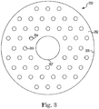
Fig. 3 illustrates a top view of a gaseous feed distribution assembly. - The figures herein follow a numbering convention in which the first digit or digits correspond to the drawing figure number and the remaining digits identify an element or component in the drawing. Similar elements or components between different figures may be identified by the use of similar digits. For example, 152 may reference element "52" in
Figure 1 , and a similar element may be referenced as 252 inFigure 2 . - Elements shown and/or described in relation to the specific embodiments herein can be added, exchanged, and/or eliminated so as to provide a number of additional embodiments of the present disclosure within the scope of the appended claims. In addition, the proportion and the relative scale of the elements provided in the figures are intended to illustrate the embodiments of the present invention, and should not be taken in a limiting sense.
- The invention provides a reactor and feed distribution assembly comprising:
- a reactor vessel having a refractory-lined inner wall surface, an outer wall surface,
- a bottom, a top, a gaseous feed distribution assembly, and a mounting plate,
- the bottom has an inner surface and an outer surface,
- the gaseous feed distribution assembly has a first surface that faces the inner surface, a second surface that is spaced apart from and faces away from the first surface, and an outer plate surface having a portion that is normal to the first surface and the second surface, wherein the gaseous feed distribution assembly defines a plurality of gas passageways, each of the plurality of gas passageways being in fluid communication with the first surface and the second surface via first apertures and second apertures, the second apertures having a greater cross-sectional area than the first apertures, and wherein distribution assembly insulation packing is disposed between a lower portion of refractory-lined inner wall surface that is nearer to where the refractory-lined inner wall surface connects to the bottom than to where the refractory-lined inner wall surface connects to the top and the gaseous feed assembly,
- the mounting plate having a first end, which is operatively connected to the bottom, and a second end, wherein the first end and the second end are spaced apart from one another and therebetween define an outer planar surface that is spaced apart from an inner planar surface, the outer planar surface being spaced apart from the refractory-lined inner wall surface, the outer plate surface being operatively connected to a portion of the inner planar surface proximate to the second end and apart from the first end,
- a gaseous feed conduit that is operatively connected to a gaseous feed conduit receiving passageway that extends through the bottom of the reactor vessel; a catalyst feed conduit that has a first end and a second end, the catalyst feed conduit extending through the refractory-lined inner wall surface and the outer wall surface such that the second end is positioned above the second surface of the gaseous feed distribution assembly;
- a catalyst feed conduit receiving passageway; and
- a catalyst feed conduit housing in which the catalyst feed conduit is slidably housed, the catalyst feed conduit being spaced apart from an inner surface of the catalyst feed conduit housing, the catalyst feed conduit housing having a first end proximate to the bottom of the reactor vessel, a second end spaced apart from the bottom of the reactor vessel and proximate to the second surface of the gaseous feed distribution assembly, and an outer surface that is spaced apart from the inner surface of the catalyst feed conduit housing and operatively connected to an inner circumferential surface of a catalyst feed conduit passageway and to the catalyst feed conduit receiving passageway, wherein catalyst feed conduit insulation is disposed between the catalyst feed conduit and the inner surface of the catalyst feed conduit housing.
- The assembly can be used for hydrocarbon conversion. For example, a gas, e.g., superheated propane and a catalyst based on e.g., alumina or alumina-silica, which includes gallium and/or platinum, may be fed to the reactor and feed distribution assembly where propane dehydrogenation occurs to provide propylene, hydrogen, and other byproducts. Advantageously, the reactor and feed distribution assembly can provide gas distribution across a bed of the reactor and feed distribution assembly to reduce propane coking, resulting in greater process efficiency as compared to other reactors where coking occurs and causes plugging, which can lead to poor distribution and loss of performance. Also, the amount of catalyst used can be reduced as a result of the uniform gas distribution across the bed of the reactor and the shape of the feed distribution assembly, which does not allow catalyst to drop below the gaseous feed distribution assembly, 150, as compared to a pipe and/or ring type of gas distributors.
- In
Fig. 1A , a reactor andfeed distribution assembly 110 includes areactor vessel 120. Thereactor vessel 120 can have various configurations. Thereactor vessel 120 can include one or more polyhedron, sphere, cylinder, cone, irregular shape, combinations thereof, and/or portions thereof. For example, thereactor vessel 120 can include a right hollow cylinder with a longitudinal axis. The reactor vessel includes a refractory-linedinner wall surface 121, anouter wall surface 122, abottom 123, atop 128, a gaseousfeed distribution assembly 150, amounting plate 160, a catalyst feedconduit receiving passageway 126, and a gaseous feedconduit receiving passageway 127. Thebottom 123 has aninner surface 124 and anouter surface 125. - The gaseous
feed distribution assembly 150 includes afirst surface 151 that faces theinner surface 124, asecond surface 152 that is spaced apart from and faces away from thefirst surface 151, and anouter plate surface 159 having a portion that is normal to thefirst surface 151 and thesecond surface 152. Theouter plate surface 159 can be welded to thefirst surface 151. Distributionassembly insulation packing 156 is disposed between a lower portion of refractory-linedinner wall surface 121 that is nearer to where the refractory-linedinner wall surface 121 connects to thebottom 123 that to where the refractory-linedinner wall surface 121 connects to thetop 128. - The
first surface 151 and/orsecond surface 152 of the gaseousfeed distribution assembly 150 can be refractory-lined, in an example. In addition, other materials with insulating properties (e.g., insulating material) can be disposed between thefirst surface 151 and thesecond surface 152. The refractory lining and/or insulating material can help prevent thefirst surface 151 of the gaseousfeed distribution assembly 150 from heating to cause the propane to coke on thefirst surface 151. - The gaseous
feed distribution assembly 150 defines a plurality ofgas passageways 155 and a catalystfeed conduit passageway 157 that has an innercircumferential surface 158. Each of the plurality ofgas passageways 155 are in fluid communication with thefirst surface 151 and thesecond surface 152 viafirst apertures 153 andsecond apertures 154. The plurality ofgas passageways 155 can be even with and/or extend past (e.g., below) thefirst surface 151 and/or thesecond surface 152. Thesecond apertures 154 can have a greater cross-sectional area than thefirst apertures 153, e.g., when a cross section of thesecond apertures 154 and thefirst apertures 153 are determined perpendicular to a longitudinal axis of one or more of thegas passageways 155 and a longitudinal axis of the catalyst feed tube. - The
first apertures 153 and thesecond apertures 154 of the gaseousfeed distribution assembly 150 can have uniform and/or varying cross-sectional areas, for example to help provide that an even distribution of gas passes through each of the plurality of gas passageways. For instance, gas passageways that are nearer togaseous feed conduit 130 can have a greater pressure difference between thefirst surface 151 and thesecond surface 152 of the gaseousfeed distribution assembly 150. As such,first apertures 153 of the gaseousfeed distribution assembly 150 that are nearer to thegaseous feed conduit 130 can have a smaller cross-sectional area thanfirst apertures 153 that are further from thegaseous feed conduit 130 to help equilibrate a pressure differential across thegaseous distribution assembly 150. - A ratio of an inside diameter ofthe
first apertures 153 of the gaseousfeed distribution assembly 150 to an inside diameter of thesecond apertures 154 of the gaseousfeed distribution assembly 150 can be from 0.13 to 0.63 and preferably from 0.34 to 0.51. A ratio of the inside diameter of thefirst apertures 153 of the gaseousfeed distribution assembly 150 to the inside diameter of thereactor vessel 120 is from 0.003 to 0.014 and preferably from 0.008 to 0.012. A ratio of the inside diameter of thesecond apertures 154 ofthe gaseousfeed distribution assembly 150 to the inside diameter of thereactor vessel 120 is from 0.008 to 0.163 and preferably from 0.026 to 0.067. For some embodiments, e.g. embodiments including a non-circular cross-sectional area, ratios of the respective cross-sectional areas can be in the ranges discussed herein for embodiments including circular cross-sectional areas. - The reactor and
feed distribution assembly 110 includes amounting plate 160 for mounting and/or supporting the gaseousfeed distribution assembly 150 to thereactor vessel 120 at thebottom 123. Themounting plate 160 includes afirst end 161, which is operatively connected to thebottom 123, and asecond end 162. Thefirst end 161 and thesecond end 162 are spaced apart from one another and there between define an outerplanar surface 163 that is spaced apart from an innerplanar surface 164. The outerplanar surface 163 is spaced apart from the refractory-linedinner wall surface 121 and theouter plate surface 159 is operatively connected to a portion of the innerplanar surface 164 proximate to thesecond end 162 and apart from thefirst end 161. - The reactor and
feed distribution assembly 110 includes agaseous feed conduit 130 that is operatively connected to a gaseous feedconduit receiving passageway 127 that extends through thebottom 123 of thereactor vessel 120. The reactor anddistribution assembly 110 can include a plurality ofgaseous feed conduits 130. The plurality ofgaseous feed conduits 130 can be operatively connected to a plurality of gaseous feed conduit receiving passageways e.g., that encircle the longitudinal axis ofthereactor vessel 120. - The reactor and
feed distribution assembly 110 can include adeflector plate 190 spaced apart from, and operatively connected to, a portion of thefirst surface 151 of the gaseousfeed distribution assembly 150 by a plurality ofdeflector plate connectors 192. Thedeflector plate 190 can deflect and/or reduce a velocity of the gaseous feed entering thereactor vessel 120. The deflection and/or redirection in velocity can cause the gaseous feed to be more evenly distributed through the plurality ofgas passageways 155. - The
gaseous feed conduit 130 can be mounted flush with the refractory-linedinner wall surface 121 or can extend beyond the refractory-linedinner wall surface 121. A ratio of an inside diameter of thegaseous feed conduit 130 to an inside diameter of thereactor vessel 120 can be from 0.06 to 0.77 and preferably from 0.20 to 0.23. - The reactor and feed
distribution assembly 110 includes acatalyst feed conduit 140. The reactor anddistribution assembly 110 can include a plurality ofcatalyst feed conduits 140. The plurality ofcatalyst feed conduits 140 can be operatively connected to a plurality of feed conduit receiving passageways e.g., that encircle the longitudinal axis of thereactor vessel 120. - The
catalyst feed conduit 140 includes afirst end 141 and asecond end 142. Thecatalyst feed conduit 140 extends through the refractory-lined inner wall surface and the outer wall surface of thereactor vessel 120 such that thesecond end 142 is positioned above thesecond surface 152 of the gaseousfeed distribution assembly 150. For example, thecatalyst feed conduit 140 extends through a catalyst feedconduit receiving passageway 126 and the catalystfeed conduit passageway 157 such that thesecond end 142 extends beyond thesecond surface 152 of the gaseousfeed distribution assembly 150. A catalystfeed conduit cap 145 can be operatively connected to thesecond end 142 by one ormore connectors 146 that definegaps 147 through which catalyst can flow onto thesecond surface 152 of the gaseousfeed distribution assembly 150. A ratio of an inside diameter of thecatalyst feed conduit 140 to the inside diameter of thereactor vessel 120 can be from 0.08 to 0.23 and preferably from 0.12 to 0.15. - The reactor and feed
distribution assembly 110 includes a catalystfeed conduit housing 180 in which thecatalyst feed conduit 140 is slidably housed. Thecatalyst feed conduit 140 can be spaced apart from aninner surface 183 of the catalystfeed conduit housing 180. Thecatalyst feed conduit 140 is slidably housed within the catalystfeed conduit housing 180 to allow for expansion of thecatalyst feed conduit 140. For example, the catalyst feed passing through thecatalyst feed conduit 140 can be heated, causing thecatalyst feed conduit 140 to expand in length and diameter. As such, thecatalyst feed conduit 140 can expand, as compared to a reactor where thecatalyst feed conduit 140 is welded in place, which can cause a potential for the welds to crack. - The catalyst
feed conduit housing 180 includes afirst end 181 proximate to the bottom 123, asecond end 182 spaced apart from thebottom 123 of thereactor vessel 120 and proximate to thesecond surface 152 of the gaseousfeed distribution assembly 150, and anouter surface 184 that is spaced apart from theinner surface 183 of the catalystfeed conduit housing 180 and operatively connected to an innercircumferential surface 158 of the catalystfeed conduit passageway 157 and to the catalyst feedconduit receiving passageway 126. An inside diameter of thefirst surface 151 can be welded to and/or supported by the catalystfeed conduit housing 180. For some applications, additional supports can be incorporated between thefirst surface 151 and the bottom 123. -
Catalyst feed conduit 140 insulation packing 149 is disposed between thecatalyst feed conduit 140 and theinner surface 183 of the catalystfeed conduit housing 180. Thecatalyst feed conduit 140 insulation packing 149 can help maintain a temperature of the catalyst feed. For example, a temperature of a gaseous feed entering through thegaseous feed conduit 130 can be different than a temperature of the catalyst feed entering through thecatalyst feed conduit 140. For instance, where propane dehydrogenation is being performed in the reactor and feeddistribution assembly 110, propane can enter through thegaseous feed conduit 130 at 570 degrees Celsius (°C) and catalyst can enter thecatalyst feed conduit 140 at 750 degrees °C. As such, if propane contacts thecatalyst feed conduit 140, which is heated to 750 °C as a result of the catalyst flowing through it, the propane can coke and cause the reactor and feeddistribution assembly 110 to plug. - The reactor and feed
distribution assembly 110 includes acatalyst backflow diverter 170 that is operatively connected to thecatalyst feed conduit 140 proximate to thesecond end 142 of thecatalyst feed conduit 140. Thecatalyst backflow diverter 170 extends from thecatalyst feed conduit 140 and extends beyond thesecond end 182 of the catalystfeed conduit housing 180. In an example, thecatalyst backflow diverter 170 can reduce catalyst introduction into thecatalyst feed conduit 140 insulation packing 149. -
Fig. 1B illustrates the reactor and feeddistribution assembly 110, which includes thereactor vessel 120. As discussed herein, thereactor vessel 120 includes the refractory-linedinner wall surface 121, theouter wall surface 122, the bottom 123, the top 128, the gaseousfeed distribution assembly 150, the mountingplate 160 and the gaseous feedconduit receiving passageway 127. The bottom 123 has theinner surface 124 and theouter surface 125. - The gaseous
feed distribution assembly 150, as discussed herein, includes thefirst surface 151 that faces theinner surface 124, thesecond surface 152 that is spaced apart from and faces away from thefirst surface 151, and theouter plate surface 159 having a portion that is normal to thefirst surface 151 and thesecond surface 152. As illustrated, the gaseousfeed distribution assembly 150 extends over the entire inner diameter of thereactor 110. - The
outer plate surface 159 can be welded to thefirst surface 151. In an example, distribution assembly insulation packing 156 is disposed between a lower portion of refractory-linedinner wall surface 121 that is nearer to where the refractory-linedinner wall surface 121 connects to the bottom 123 that to where the refractory-linedinner wall surface 121 connects to the top 128. - The
first surface 151 and/orsecond surface 152 of the gaseousfeed distribution assembly 150 can be refractory-lined, in an example. In addition, other materials with insulating properties (e.g., insulating material) can be disposed between thefirst surface 151 and thesecond surface 152, as discussed herein. The gaseousfeed distribution assembly 150 defines a plurality ofgas passageways 155, as discussed herein. Each of the plurality ofgas passageways 155 are in fluid communication with thefirst surface 151 and thesecond surface 152 viafirst apertures 153 andsecond apertures 154. The plurality ofgas passageways 155 can be even with and/or extend past (e.g., below) thefirst surface 151 and/or thesecond surface 152. Thesecond apertures 154 can have a greater cross-sectional area than thefirst apertures 153, e.g., when a cross section of thesecond apertures 154 and thefirst apertures 153 are determined perpendicular to a longitudinal axis of one or more of thegas passageways 155 and a longitudinal axis of the catalyst feed tube. - The
first apertures 153 and thesecond apertures 154 of the gaseousfeed distribution assembly 150 can have uniform and/or varying cross-sectional areas, as discussed herein. A ratio of an inside diameter of thefirst apertures 153 of the gaseousfeed distribution assembly 150 to an inside diameter of thesecond apertures 154 of the gaseousfeed distribution assembly 150 can be from 0.13 to 0.63 and preferably from 0.34 to 0.51. A ratio of the inside diameter of thefirst apertures 153 of the gaseousfeed distribution assembly 150 to the inside diameter of thereactor vessel 120 is from 0.003 to 0.014 and preferably from 0.008 to 0.012. A ratio of the inside diameter of thesecond apertures 154 of the gaseousfeed distribution assembly 150 to the inside diameter of thereactor vessel 120 is from 0.008 to 0.163 and preferably from 0.026 to 0.067. - The reactor and feed
distribution assembly 110 also includes a mountingplate 160 for mounting and/or supporting the gaseousfeed distribution assembly 150 to thereactor vessel 120 at the bottom 123, as discussed herein. The mountingplate 160 includes afirst end 161, which is operatively connected to the bottom 123, and asecond end 162. Thefirst end 161 and thesecond end 162 are spaced apart from one another and there between define an outerplanar surface 163 that is spaced apart from an innerplanar surface 164. The outerplanar surface 163 is spaced apart from the refractory-linedinner wall surface 121 and theouter plate surface 159 is operatively connected to a portion of the innerplanar surface 164 proximate to thesecond end 162 and apart from thefirst end 161. - The reactor and feed
distribution assembly 110 seen inFig. 1B includes thegaseous feed conduit 130 that is operatively connected to the gaseous feedconduit receiving passageway 127 that extends through thebottom 123 of thereactor vessel 120, as discussed herein. Thegaseous feed conduit 130 can be mounted flush with the refractory-linedinner wall surface 121 or can extend beyond the refractory-linedinner wall surface 121. A ratio of an inside diameter of thegaseous feed conduit 130 to an inside diameter of thereactor vessel 120 can be from 0.06 to 0.77 and preferably from 0.20 to 0.23. - The reactor and feed
distribution assembly 110 illustrated inFig. 1B can also include adeflector plate 190 spaced apart from, and operatively connected to, a portion of thefirst surface 151 of the gaseousfeed distribution assembly 150 by a plurality ofdeflector plate connectors 192, as discussed herein. - The reactor and feed
distribution assembly 110 ofFig. 1B includes thecatalyst feed conduit 140 which can enter in either an upward (as shown inFig. 1B ) or a downward orientation. Thecatalyst feed conduit 140 includes afirst end 141 and asecond end 142. As illustrated inFig. 1B , thecatalyst feed conduit 140 extends through the refractory-linedinner wall surface 121 and theouter wall surface 122 of thereactor vessel 120 such that thesecond end 142 is positioned above thesecond surface 152 of the gaseousfeed distribution assembly 150. For this embodiment (not according to the invention), thecatalyst feed conduit 140 can be welded to thereactor vessel 120. - As shown in
Fig. 1B , the catalystfeed conduit cap 145 can be operatively connected to thesecond end 142 by one ormore connectors 146 that definegaps 147 through which catalyst can flow onto thesecond surface 152 of the gaseousfeed distribution assembly 150. The ratio of the inside diameter of thecatalyst feed conduit 140 to the inside diameter of thereactor vessel 120 can be from 0.08 to 0.23 and preferably from 0.12 to 0.15. - The reactor and
distribution assembly 110 can include a plurality ofcatalyst feed conduits 140. The plurality ofcatalyst feed conduits 140 can be operatively connected to a plurality of feed conduit receiving passageways e.g., that encircle the longitudinal axis of thereactor vessel 120. In an additional embodiment, a combination of catalyst entry through the catalyst feedconduit receiving passageway 126 and the catalystfeed conduit passageway 157 as shown inFig. 1A and the opening in thereactor vessel 120 as shown inFig. 1B is also possible. - The reactor and feed
distribution assembly 110 can also include verticalmechanical supports 193, as illustrated inFig. 1B . As illustrated, the verticalmechanical supports 193 can be positioned between and secured to theinner surface 124 of thevessel 120 and thefirst surface 151 of the gaseousfeed distributor assembly 150, which faces theinner surface 124. The verticalmechanical supports 193 can help to maintain structural stability for the gaseousfeed distribution assembly 150 and are provided in a number and configuration that is appropriately for the load provided by the gaseousfeed distribution assembly 150. - As shown in
Fig. 2 , acatalyst feed conduit 240 can be split into a plurality of second ends 242 that extend radially from thecatalyst feed conduit 240. A plurality of catalyst feed conduit caps 245 can be operatively connected to each of the plurality of second ends 242 by one ormore connectors 246 that definegaps 247. Catalyst can flow through afirst end 241 of thecatalyst feed conduit 240, through catalystfeed conduit arms 248, and through thegaps 247 onto asecond surface 252 of a gaseousfeed distribution assembly 250. The catalystfeed conduit arms 248 can extend over the gaseousfeed distribution assembly 250, which can help to distribute catalyst over a diameter of the gaseousfeed distribution assembly 250. The catalystfeed conduit arms 248 can be parallel with thesecond surface 152 of thegaseous distribution assembly 250, can extend away from thesecond surface 252 of thegaseous distribution assembly 250, and/or extend toward thesecond surface 252 of thegaseous distribution assembly 250 to help promote mixing of the catalyst and the gas. - As shown in
Fig. 3 , the gaseousfeed distribution assembly 350 can include asecond surface 352 andouter plate surface 359. Thesecond surface 352 can include a plurality of gas passageways 355, formed bysecond apertures 354 of the gaseousfeed distribution assembly 350. The plurality of gas passageways 355 can be arranged around catalystfeed conduit passageway 357 in a geometric pattern. The geometric pattern may be different for various applications. For example, the plurality of gas passageways 355 can be arranged around the catalystfeed conduit passageway 357 in a grid and/or concentrically. The gaseousfeed distribution assembly 250 can include 10 to 50 gas passageways per square meter and preferably between 20 to 35 gas passageways per square meter, however other numbers of gas passageways per square meter may also be possible.
Claims (10)
- A reactor and feed distribution assembly comprising:a reactor vessel (120) having a refractory-lined inner wall surface (121), an outer wall surface (122), a bottom (123), a top (128), a gaseous feed distribution assembly (150, 250, 350), and a mounting plate (160), wherein:the bottom (123) has an inner surface (124) and an outer surface (125),the gaseous feed distribution assembly (150, 250, 350) has a first surface (151) that faces the inner surface (124), a second surface (152,252,352) that is spaced apart from and faces away from the first surface (151), and an outer plate surface (159, 359) having a portion that is normal to the first surface (151) and the second surface (152,252,352), wherein the gaseous feed distribution assembly (150, 250, 350) defines a plurality of gas passageways (155, 355), each of the plurality of gas passageways (155, 355) being in fluid communication with the first surface (151) and the second surface (152, 252, 352) via first apertures (153) and second apertures (154, 354), the second apertures (154, 354) having a greater cross-sectional area than the first apertures (153), and wherein distribution assembly insulation packing (156) is disposed between a lower portion of refractory-lined inner wall surface that is nearer to where the refractory-lined inner wall surface connects to the bottom (123) than to where the refractory-lined inner wall surface connects to the top (128) and the gaseous feed assembly (150, 250, 350),the mounting plate (160) having a first end (161), which is operatively connected to the bottom (123), and a second end (162), wherein the first end (161) and the second end (162) are spaced apart from one another and therebetween define an outer planar surface (163) that is spaced apart from an inner planar surface (164), the outer planar surface (163) being spaced apart from the refractory-lined inner wall surface, the outer plate surface (159, 359) being operatively connected to a portion of the inner planar surface (164) proximate to the second end (162) and apart from the first end (161),a gaseous feed conduit (130) that is operatively connected to a gaseous feed conduit receiving passageway (127) that extends through the bottom (123) of the reactor vessel (120);a catalyst feed conduit (140, 240) that has a first end (141, 241) and a second end (142, 242), the catalyst feed conduit (140, 240) extending through the refractory-lined inner wall surface and the outer wall surface (122) such that the second end (142, 242) is positioned above the second surface (152, 252, 352) of the gaseous feed distribution assembly (150, 250, 350);a catalyst feed conduit receiving passageway (126); anda catalyst feed conduit housing (180) in which the catalyst feed conduit is slidably housed, the catalyst feed conduit (140, 240) being spaced apart from an inner surface (183) of the catalyst feed conduit housing (180), the catalyst feed conduit housing (180) having a first end (181) proximate to the bottom (123) of the reactor vessel (120), a second end (182) spaced apart from the bottom (123) of the reactor vessel (120) and proximate to the second surface (152, 252, 352) of the gaseous feed distribution assembly (150, 250, 350), and an outer surface (184) that is spaced apart from the inner surface (183) of the catalyst feed conduit housing (180) and operatively connected to an inner circumferential surface (158) of a catalyst feed conduit passageway (157, 257) and to the catalyst feed conduit receiving passageway (126), wherein catalyst feed conduit insulation (149) is disposed between the catalyst feed conduit (140, 240) and the inner surface (183) of the catalyst feed conduit housing (180).
- The reactor and feed distribution assembly of claim 1, further comprising a plurality of gaseous feed conduits.
- The reactor and feed distribution assembly of claim 1, further comprising a plurality of catalyst feed conduits.
- The reactor and feed distribution assembly of claim 1, wherein a ratio of an inside diameter of the first apertures of the gaseous feed distribution assembly to an inside diameter of the second apertures of the gaseous feed distribution assembly is from 0.13 to 0.63.
- The reactor and feed distribution assembly of claim 1, wherein a ratio of the inside diameter of the first apertures of the gaseous feed distribution assembly to an inside diameter of the reactor vessel is from 0.003 to 0.014.
- The reactor and feed distribution assembly of claim 1, wherein a ratio of the inside diameter of the second apertures of the gaseous feed distribution assembly to the inside diameter of the reactor vessel is from 0.008 to 0.163.
- The reactor and feed distribution assembly of claim 1, wherein a ratio of an inside diameter of the gaseous feed conduit to the inside diameter of the reactor vessel is from 0.06 to 0.77.
- The reactor and feed distribution assembly of claim 1, wherein a ratio of an inside diameter of the catalyst feed conduit to the inside diameter of the reactor vessel is from 0.08 to 0.23.
- The reactor and feed distribution assembly of claim 1, further comprising a deflector plate spaced apart from, and operatively connected to, a portion of the first surface of the gaseous feed distribution assembly by way of a plurality of deflector plate connectors.
- The reactor and feed distribution assembly of any one of the preceding claims, further comprising:a catalyst backflow diverter that is operatively connected to the catalyst feed conduit proximate to the second end of the catalyst feed conduit, the catalyst backflow diverter extending from the catalyst feed conduit and extending beyond the second end of the catalyst feed conduit housing.
Applications Claiming Priority (2)
| Application Number | Priority Date | Filing Date | Title |
|---|---|---|---|
| US201261701785P | 2012-09-17 | 2012-09-17 | |
| PCT/US2013/059985 WO2014043638A2 (en) | 2012-09-17 | 2013-09-16 | Reactor and feed distribution assembly |
Publications (2)
| Publication Number | Publication Date |
|---|---|
| EP2895261A2 EP2895261A2 (en) | 2015-07-22 |
| EP2895261B1 true EP2895261B1 (en) | 2017-03-15 |
Family
ID=49231647
Family Applications (1)
| Application Number | Title | Priority Date | Filing Date |
|---|---|---|---|
| EP13766457.9A Active EP2895261B1 (en) | 2012-09-17 | 2013-09-16 | Fluidized bed reactor and feed distribution assembly |
Country Status (6)
| Country | Link |
|---|---|
| US (1) | US9370759B2 (en) |
| EP (1) | EP2895261B1 (en) |
| CN (1) | CN104936688B (en) |
| AR (1) | AR092578A1 (en) |
| BR (1) | BR112015005747B1 (en) |
| WO (1) | WO2014043638A2 (en) |
Families Citing this family (14)
| Publication number | Priority date | Publication date | Assignee | Title |
|---|---|---|---|---|
| KR102579627B1 (en) | 2015-03-30 | 2023-09-18 | 다우 글로벌 테크놀로지스 엘엘씨 | Integrated C3-C4 hydrocarbon dehydrogenation process |
| US9815040B2 (en) * | 2015-06-26 | 2017-11-14 | Dow Global Technologies Llc | Fluid solids contacting device |
| AR111124A1 (en) | 2017-03-13 | 2019-06-05 | Dow Global Technologies Llc | METHODS FOR MANUFACTURING LIGHT OLEFINS FROM DIFFERENT POWER SUPPLY CURRENTS |
| AR111237A1 (en) | 2017-03-13 | 2019-06-19 | Dow Global Technologies Llc | METHODS AND APPLIANCES TO FORM LIGHT OLEFINS BY CRAQUEO |
| AR112516A1 (en) | 2017-07-31 | 2019-11-06 | Dow Global Technologies Llc | METHODS AND APPARATUS FOR PROCESSING GAS CURRENTS |
| US10576455B2 (en) * | 2018-03-22 | 2020-03-03 | Air Products And Chemicals, Inc. | Particle loading method and apparatus for a radial flow vessel |
| BR112021003382A2 (en) | 2018-08-31 | 2021-05-18 | Dow Global Technologies Llc | methods for dehydrogenating hydrocarbons. |
| KR102725736B1 (en) | 2018-08-31 | 2024-11-06 | 다우 글로벌 테크놀로지스 엘엘씨 | Method for producing hydrogen-selective oxygen carrier material |
| CN116367918A (en) | 2020-09-30 | 2023-06-30 | 陶氏环球技术有限责任公司 | Chemical feed dispenser and method of use |
| KR20230079118A (en) | 2020-09-30 | 2023-06-05 | 다우 글로벌 테크놀로지스 엘엘씨 | Chemical Feed Distributors and Methods of Using The Same |
| US20240307841A1 (en) * | 2021-06-30 | 2024-09-19 | Dow Global Technologies Llc | Chemical processing vessels having plate grid distributors and methods of operating the same |
| WO2024059554A1 (en) | 2022-09-14 | 2024-03-21 | Dow Global Technologies Llc | Methods for dehydrogenating hydrocarbons by thermal dehydrogenation |
| CN120076862A (en) * | 2022-10-28 | 2025-05-30 | 陶氏环球技术有限责任公司 | Chemical treatment vessel with flow director and method of operating the same |
| CN120225272A (en) * | 2022-11-29 | 2025-06-27 | 陶氏环球技术有限责任公司 | Granular solid distributor suitable for distributing multiple granular solid streams |
Family Cites Families (9)
| Publication number | Priority date | Publication date | Assignee | Title |
|---|---|---|---|---|
| DE1249829B (en) * | 1963-07-15 | 1967-09-14 | Dorr-Oliver Incorporated, Stamford, Conn. (V. St. A.) | Gas distribution plate for fluidized bed devices |
| US3370361A (en) * | 1965-04-27 | 1968-02-27 | Lummus Co | Grid for fluidized solid vessels |
| US4309948A (en) * | 1980-08-07 | 1982-01-12 | Combustion Engineering, Inc. | Solids feed nozzle for fluidized bed |
| US4405444A (en) * | 1982-11-08 | 1983-09-20 | Ashland Oil, Inc. | Method and means for charging foamed residual oils in contact with fluid solid particulate material |
| US6076810A (en) * | 1997-10-21 | 2000-06-20 | Exxon Research And Engineering Co. | Throat and cone gas injector and gas distribution grid for slurry reactor |
| US6797239B1 (en) | 2000-11-22 | 2004-09-28 | Shell Oil Company | Spent catalyst distributor |
| US7179426B2 (en) * | 2002-09-12 | 2007-02-20 | Chevron Phillips Chemical Company, Lp | Large catalyst activator |
| JP5103282B2 (en) * | 2008-05-30 | 2012-12-19 | 旭化成ケミカルズ株式会社 | Fluidized bed reactor and gas phase exothermic reaction method using the same |
| CN201760272U (en) * | 2010-06-01 | 2011-03-16 | 滨化集团股份有限公司 | Novel gas distributor of acetylene chlorination tower |
-
2013
- 2013-09-16 CN CN201380048116.6A patent/CN104936688B/en active Active
- 2013-09-16 BR BR112015005747-0A patent/BR112015005747B1/en active IP Right Grant
- 2013-09-16 WO PCT/US2013/059985 patent/WO2014043638A2/en not_active Ceased
- 2013-09-16 EP EP13766457.9A patent/EP2895261B1/en active Active
- 2013-09-16 US US14/425,902 patent/US9370759B2/en active Active
- 2013-09-16 AR ARP130103309A patent/AR092578A1/en active IP Right Grant
Non-Patent Citations (1)
| Title |
|---|
| None * |
Also Published As
| Publication number | Publication date |
|---|---|
| AR092578A1 (en) | 2015-04-22 |
| CN104936688B (en) | 2016-11-23 |
| EP2895261A2 (en) | 2015-07-22 |
| BR112015005747A2 (en) | 2017-07-04 |
| WO2014043638A3 (en) | 2014-07-10 |
| BR112015005747B1 (en) | 2020-02-18 |
| US20150231586A1 (en) | 2015-08-20 |
| US9370759B2 (en) | 2016-06-21 |
| CN104936688A (en) | 2015-09-23 |
| WO2014043638A2 (en) | 2014-03-20 |
Similar Documents
| Publication | Publication Date | Title |
|---|---|---|
| US9370759B2 (en) | Reactor and feed distribution assembly | |
| US9447901B2 (en) | Radial flow process and apparatus | |
| US11459282B2 (en) | Methods for forming light olefins by cracking | |
| ATE240378T1 (en) | INSERT INJECTION SYSTEM FOR CATALYTIC CRACKING PROCESS | |
| MX2011010283A (en) | Devices for injection of gaseous streams into a bed of fluidized solids. | |
| EP2621624B1 (en) | Feed nozzle assembly | |
| CA1163781A (en) | Reactor for exothermic reactions and process for the preparation of hydrocarbons using this reactor | |
| KR20060115750A (en) | Feed nozzle assembly | |
| JP7158412B2 (en) | Novel apparatus for dispensing multiphase mixtures in chambers containing flowing media | |
| US20140231309A1 (en) | Distribution tray for distributing a polyphasic mixture with inclined peripheral conduits | |
| JP5823911B2 (en) | Mixing device for mixing raw material and catalyst in fluid catalytic cracking unit | |
| CA1172832A (en) | Reactor having dual upflow catalyst beds | |
| WO2011062729A2 (en) | Centerpipe design for radial flow reactor | |
| US20240316522A1 (en) | Plate grid distributors and methods of using the same | |
| US10792635B2 (en) | Distributor and down flow catalytic reactor comprising same | |
| US10406497B2 (en) | Reactor bed vessel and support assembly | |
| EP3414000A1 (en) | Enhanced efficiency endothermic reactor for syngas production with flexible heat recovery to meet low export steam generation. | |
| KR20110117713A (en) | Molded cover plate structure for flexible pressure containment | |
| RU2861288C2 (en) | Tray distributor and method of using the same | |
| KR101846099B1 (en) | Dehydrogenation reactor | |
| KR101606879B1 (en) | Chimney for distributor, a distributor and a hydrotreater reactor comprising same | |
| JP2024525384A (en) | Plate grid distributor and method of using same | |
| KR20190120762A (en) | Reactor with reduced thickness catalyst beds | |
| KR20160069057A (en) | Dehydogenation reactor |
Legal Events
| Date | Code | Title | Description |
|---|---|---|---|
| PUAI | Public reference made under article 153(3) epc to a published international application that has entered the european phase |
Free format text: ORIGINAL CODE: 0009012 |
|
| 17P | Request for examination filed |
Effective date: 20150417 |
|
| AK | Designated contracting states |
Kind code of ref document: A2 Designated state(s): AL AT BE BG CH CY CZ DE DK EE ES FI FR GB GR HR HU IE IS IT LI LT LU LV MC MK MT NL NO PL PT RO RS SE SI SK SM TR |
|
| AX | Request for extension of the european patent |
Extension state: BA ME |
|
| RAP1 | Party data changed (applicant data changed or rights of an application transferred) |
Owner name: DOW GLOBAL TECHNOLOGIES LLC |
|
| DAX | Request for extension of the european patent (deleted) | ||
| GRAP | Despatch of communication of intention to grant a patent |
Free format text: ORIGINAL CODE: EPIDOSNIGR1 |
|
| INTG | Intention to grant announced |
Effective date: 20160606 |
|
| GRAJ | Information related to disapproval of communication of intention to grant by the applicant or resumption of examination proceedings by the epo deleted |
Free format text: ORIGINAL CODE: EPIDOSDIGR1 |
|
| GRAP | Despatch of communication of intention to grant a patent |
Free format text: ORIGINAL CODE: EPIDOSNIGR1 |
|
| INTC | Intention to grant announced (deleted) | ||
| INTG | Intention to grant announced |
Effective date: 20161014 |
|
| GRAS | Grant fee paid |
Free format text: ORIGINAL CODE: EPIDOSNIGR3 |
|
| GRAA | (expected) grant |
Free format text: ORIGINAL CODE: 0009210 |
|
| AK | Designated contracting states |
Kind code of ref document: B1 Designated state(s): AL AT BE BG CH CY CZ DE DK EE ES FI FR GB GR HR HU IE IS IT LI LT LU LV MC MK MT NL NO PL PT RO RS SE SI SK SM TR |
|
| REG | Reference to a national code |
Ref country code: CH Ref legal event code: EP Ref country code: GB Ref legal event code: FG4D |
|
| REG | Reference to a national code |
Ref country code: IE Ref legal event code: FG4D |
|
| REG | Reference to a national code |
Ref country code: AT Ref legal event code: REF Ref document number: 874973 Country of ref document: AT Kind code of ref document: T Effective date: 20170415 |
|
| REG | Reference to a national code |
Ref country code: DE Ref legal event code: R096 Ref document number: 602013018614 Country of ref document: DE |
|
| REG | Reference to a national code |
Ref country code: NL Ref legal event code: FP |
|
| REG | Reference to a national code |
Ref country code: LT Ref legal event code: MG4D |
|
| PG25 | Lapsed in a contracting state [announced via postgrant information from national office to epo] |
Ref country code: FI Free format text: LAPSE BECAUSE OF FAILURE TO SUBMIT A TRANSLATION OF THE DESCRIPTION OR TO PAY THE FEE WITHIN THE PRESCRIBED TIME-LIMIT Effective date: 20170315 Ref country code: LT Free format text: LAPSE BECAUSE OF FAILURE TO SUBMIT A TRANSLATION OF THE DESCRIPTION OR TO PAY THE FEE WITHIN THE PRESCRIBED TIME-LIMIT Effective date: 20170315 Ref country code: NO Free format text: LAPSE BECAUSE OF FAILURE TO SUBMIT A TRANSLATION OF THE DESCRIPTION OR TO PAY THE FEE WITHIN THE PRESCRIBED TIME-LIMIT Effective date: 20170615 Ref country code: GR Free format text: LAPSE BECAUSE OF FAILURE TO SUBMIT A TRANSLATION OF THE DESCRIPTION OR TO PAY THE FEE WITHIN THE PRESCRIBED TIME-LIMIT Effective date: 20170616 Ref country code: HR Free format text: LAPSE BECAUSE OF FAILURE TO SUBMIT A TRANSLATION OF THE DESCRIPTION OR TO PAY THE FEE WITHIN THE PRESCRIBED TIME-LIMIT Effective date: 20170315 |
|
| REG | Reference to a national code |
Ref country code: AT Ref legal event code: MK05 Ref document number: 874973 Country of ref document: AT Kind code of ref document: T Effective date: 20170315 |
|
| PG25 | Lapsed in a contracting state [announced via postgrant information from national office to epo] |
Ref country code: SE Free format text: LAPSE BECAUSE OF FAILURE TO SUBMIT A TRANSLATION OF THE DESCRIPTION OR TO PAY THE FEE WITHIN THE PRESCRIBED TIME-LIMIT Effective date: 20170315 Ref country code: BG Free format text: LAPSE BECAUSE OF FAILURE TO SUBMIT A TRANSLATION OF THE DESCRIPTION OR TO PAY THE FEE WITHIN THE PRESCRIBED TIME-LIMIT Effective date: 20170615 Ref country code: LV Free format text: LAPSE BECAUSE OF FAILURE TO SUBMIT A TRANSLATION OF THE DESCRIPTION OR TO PAY THE FEE WITHIN THE PRESCRIBED TIME-LIMIT Effective date: 20170315 Ref country code: RS Free format text: LAPSE BECAUSE OF FAILURE TO SUBMIT A TRANSLATION OF THE DESCRIPTION OR TO PAY THE FEE WITHIN THE PRESCRIBED TIME-LIMIT Effective date: 20170315 |
|
| PG25 | Lapsed in a contracting state [announced via postgrant information from national office to epo] |
Ref country code: RO Free format text: LAPSE BECAUSE OF FAILURE TO SUBMIT A TRANSLATION OF THE DESCRIPTION OR TO PAY THE FEE WITHIN THE PRESCRIBED TIME-LIMIT Effective date: 20170315 Ref country code: IT Free format text: LAPSE BECAUSE OF FAILURE TO SUBMIT A TRANSLATION OF THE DESCRIPTION OR TO PAY THE FEE WITHIN THE PRESCRIBED TIME-LIMIT Effective date: 20170315 Ref country code: AT Free format text: LAPSE BECAUSE OF FAILURE TO SUBMIT A TRANSLATION OF THE DESCRIPTION OR TO PAY THE FEE WITHIN THE PRESCRIBED TIME-LIMIT Effective date: 20170315 Ref country code: ES Free format text: LAPSE BECAUSE OF FAILURE TO SUBMIT A TRANSLATION OF THE DESCRIPTION OR TO PAY THE FEE WITHIN THE PRESCRIBED TIME-LIMIT Effective date: 20170315 Ref country code: EE Free format text: LAPSE BECAUSE OF FAILURE TO SUBMIT A TRANSLATION OF THE DESCRIPTION OR TO PAY THE FEE WITHIN THE PRESCRIBED TIME-LIMIT Effective date: 20170315 Ref country code: SK Free format text: LAPSE BECAUSE OF FAILURE TO SUBMIT A TRANSLATION OF THE DESCRIPTION OR TO PAY THE FEE WITHIN THE PRESCRIBED TIME-LIMIT Effective date: 20170315 Ref country code: CZ Free format text: LAPSE BECAUSE OF FAILURE TO SUBMIT A TRANSLATION OF THE DESCRIPTION OR TO PAY THE FEE WITHIN THE PRESCRIBED TIME-LIMIT Effective date: 20170315 |
|
| PG25 | Lapsed in a contracting state [announced via postgrant information from national office to epo] |
Ref country code: SM Free format text: LAPSE BECAUSE OF FAILURE TO SUBMIT A TRANSLATION OF THE DESCRIPTION OR TO PAY THE FEE WITHIN THE PRESCRIBED TIME-LIMIT Effective date: 20170315 Ref country code: IS Free format text: LAPSE BECAUSE OF FAILURE TO SUBMIT A TRANSLATION OF THE DESCRIPTION OR TO PAY THE FEE WITHIN THE PRESCRIBED TIME-LIMIT Effective date: 20170715 Ref country code: PT Free format text: LAPSE BECAUSE OF FAILURE TO SUBMIT A TRANSLATION OF THE DESCRIPTION OR TO PAY THE FEE WITHIN THE PRESCRIBED TIME-LIMIT Effective date: 20170717 Ref country code: PL Free format text: LAPSE BECAUSE OF FAILURE TO SUBMIT A TRANSLATION OF THE DESCRIPTION OR TO PAY THE FEE WITHIN THE PRESCRIBED TIME-LIMIT Effective date: 20170315 |
|
| REG | Reference to a national code |
Ref country code: DE Ref legal event code: R097 Ref document number: 602013018614 Country of ref document: DE |
|
| PLBE | No opposition filed within time limit |
Free format text: ORIGINAL CODE: 0009261 |
|
| STAA | Information on the status of an ep patent application or granted ep patent |
Free format text: STATUS: NO OPPOSITION FILED WITHIN TIME LIMIT |
|
| PG25 | Lapsed in a contracting state [announced via postgrant information from national office to epo] |
Ref country code: DK Free format text: LAPSE BECAUSE OF FAILURE TO SUBMIT A TRANSLATION OF THE DESCRIPTION OR TO PAY THE FEE WITHIN THE PRESCRIBED TIME-LIMIT Effective date: 20170315 |
|
| 26N | No opposition filed |
Effective date: 20171218 |
|
| PG25 | Lapsed in a contracting state [announced via postgrant information from national office to epo] |
Ref country code: SI Free format text: LAPSE BECAUSE OF FAILURE TO SUBMIT A TRANSLATION OF THE DESCRIPTION OR TO PAY THE FEE WITHIN THE PRESCRIBED TIME-LIMIT Effective date: 20170315 |
|
| REG | Reference to a national code |
Ref country code: CH Ref legal event code: PL |
|
| GBPC | Gb: european patent ceased through non-payment of renewal fee |
Effective date: 20170916 |
|
| PG25 | Lapsed in a contracting state [announced via postgrant information from national office to epo] |
Ref country code: MC Free format text: LAPSE BECAUSE OF FAILURE TO SUBMIT A TRANSLATION OF THE DESCRIPTION OR TO PAY THE FEE WITHIN THE PRESCRIBED TIME-LIMIT Effective date: 20170315 |
|
| REG | Reference to a national code |
Ref country code: IE Ref legal event code: MM4A |
|
| REG | Reference to a national code |
Ref country code: BE Ref legal event code: MM Effective date: 20170930 |
|
| PG25 | Lapsed in a contracting state [announced via postgrant information from national office to epo] |
Ref country code: LU Free format text: LAPSE BECAUSE OF NON-PAYMENT OF DUE FEES Effective date: 20170916 |
|
| REG | Reference to a national code |
Ref country code: FR Ref legal event code: ST Effective date: 20180531 |
|
| PG25 | Lapsed in a contracting state [announced via postgrant information from national office to epo] |
Ref country code: GB Free format text: LAPSE BECAUSE OF NON-PAYMENT OF DUE FEES Effective date: 20170916 Ref country code: IE Free format text: LAPSE BECAUSE OF NON-PAYMENT OF DUE FEES Effective date: 20170916 Ref country code: LI Free format text: LAPSE BECAUSE OF NON-PAYMENT OF DUE FEES Effective date: 20170930 Ref country code: CH Free format text: LAPSE BECAUSE OF NON-PAYMENT OF DUE FEES Effective date: 20170930 |
|
| PG25 | Lapsed in a contracting state [announced via postgrant information from national office to epo] |
Ref country code: BE Free format text: LAPSE BECAUSE OF NON-PAYMENT OF DUE FEES Effective date: 20170930 Ref country code: FR Free format text: LAPSE BECAUSE OF NON-PAYMENT OF DUE FEES Effective date: 20171002 |
|
| PG25 | Lapsed in a contracting state [announced via postgrant information from national office to epo] |
Ref country code: MT Free format text: LAPSE BECAUSE OF NON-PAYMENT OF DUE FEES Effective date: 20170916 |
|
| PG25 | Lapsed in a contracting state [announced via postgrant information from national office to epo] |
Ref country code: HU Free format text: LAPSE BECAUSE OF FAILURE TO SUBMIT A TRANSLATION OF THE DESCRIPTION OR TO PAY THE FEE WITHIN THE PRESCRIBED TIME-LIMIT; INVALID AB INITIO Effective date: 20130916 |
|
| PG25 | Lapsed in a contracting state [announced via postgrant information from national office to epo] |
Ref country code: CY Free format text: LAPSE BECAUSE OF FAILURE TO SUBMIT A TRANSLATION OF THE DESCRIPTION OR TO PAY THE FEE WITHIN THE PRESCRIBED TIME-LIMIT Effective date: 20170315 |
|
| PG25 | Lapsed in a contracting state [announced via postgrant information from national office to epo] |
Ref country code: MK Free format text: LAPSE BECAUSE OF FAILURE TO SUBMIT A TRANSLATION OF THE DESCRIPTION OR TO PAY THE FEE WITHIN THE PRESCRIBED TIME-LIMIT Effective date: 20170315 |
|
| PG25 | Lapsed in a contracting state [announced via postgrant information from national office to epo] |
Ref country code: TR Free format text: LAPSE BECAUSE OF FAILURE TO SUBMIT A TRANSLATION OF THE DESCRIPTION OR TO PAY THE FEE WITHIN THE PRESCRIBED TIME-LIMIT Effective date: 20170315 |
|
| PG25 | Lapsed in a contracting state [announced via postgrant information from national office to epo] |
Ref country code: AL Free format text: LAPSE BECAUSE OF FAILURE TO SUBMIT A TRANSLATION OF THE DESCRIPTION OR TO PAY THE FEE WITHIN THE PRESCRIBED TIME-LIMIT Effective date: 20170315 |
|
| P01 | Opt-out of the competence of the unified patent court (upc) registered |
Effective date: 20230526 |
|
| PGFP | Annual fee paid to national office [announced via postgrant information from national office to epo] |
Ref country code: NL Payment date: 20250704 Year of fee payment: 13 |
|
| PGFP | Annual fee paid to national office [announced via postgrant information from national office to epo] |
Ref country code: DE Payment date: 20250702 Year of fee payment: 13 |