EP2894809A1 - Synchronization of edge encoded data by a digital phase-locked loop - Google Patents
Synchronization of edge encoded data by a digital phase-locked loop Download PDFInfo
- Publication number
- EP2894809A1 EP2894809A1 EP15150792.8A EP15150792A EP2894809A1 EP 2894809 A1 EP2894809 A1 EP 2894809A1 EP 15150792 A EP15150792 A EP 15150792A EP 2894809 A1 EP2894809 A1 EP 2894809A1
- Authority
- EP
- European Patent Office
- Prior art keywords
- data
- iteration
- counter
- edge
- count value
- Prior art date
- Legal status (The legal status is an assumption and is not a legal conclusion. Google has not performed a legal analysis and makes no representation as to the accuracy of the status listed.)
- Withdrawn
Links
- 238000004891 communication Methods 0.000 claims abstract description 15
- 238000005070 sampling Methods 0.000 claims abstract description 15
- 238000000034 method Methods 0.000 claims description 31
- 238000001514 detection method Methods 0.000 claims description 5
- 230000007704 transition Effects 0.000 description 32
- 238000003491 array Methods 0.000 description 2
- 230000005540 biological transmission Effects 0.000 description 2
- 238000004364 calculation method Methods 0.000 description 2
- 238000010586 diagram Methods 0.000 description 2
- 230000002093 peripheral effect Effects 0.000 description 2
- 230000001360 synchronised effect Effects 0.000 description 2
- 238000013500 data storage Methods 0.000 description 1
- 238000012986 modification Methods 0.000 description 1
- 230000004048 modification Effects 0.000 description 1
- 238000012545 processing Methods 0.000 description 1
- 230000003068 static effect Effects 0.000 description 1
- 238000012795 verification Methods 0.000 description 1
Images


Classifications
-
- H—ELECTRICITY
- H04—ELECTRIC COMMUNICATION TECHNIQUE
- H04L—TRANSMISSION OF DIGITAL INFORMATION, e.g. TELEGRAPHIC COMMUNICATION
- H04L7/00—Arrangements for synchronising receiver with transmitter
- H04L7/02—Speed or phase control by the received code signals, the signals containing no special synchronisation information
- H04L7/033—Speed or phase control by the received code signals, the signals containing no special synchronisation information using the transitions of the received signal to control the phase of the synchronising-signal-generating means, e.g. using a phase-locked loop
- H04L7/0331—Speed or phase control by the received code signals, the signals containing no special synchronisation information using the transitions of the received signal to control the phase of the synchronising-signal-generating means, e.g. using a phase-locked loop with a digital phase-locked loop [PLL] processing binary samples, e.g. add/subtract logic for correction of receiver clock
-
- H—ELECTRICITY
- H04—ELECTRIC COMMUNICATION TECHNIQUE
- H04L—TRANSMISSION OF DIGITAL INFORMATION, e.g. TELEGRAPHIC COMMUNICATION
- H04L25/00—Baseband systems
- H04L25/38—Synchronous or start-stop systems, e.g. for Baudot code
- H04L25/40—Transmitting circuits; Receiving circuits
- H04L25/49—Transmitting circuits; Receiving circuits using code conversion at the transmitter; using predistortion; using insertion of idle bits for obtaining a desired frequency spectrum; using three or more amplitude levels ; Baseband coding techniques specific to data transmission systems
- H04L25/493—Transmitting circuits; Receiving circuits using code conversion at the transmitter; using predistortion; using insertion of idle bits for obtaining a desired frequency spectrum; using three or more amplitude levels ; Baseband coding techniques specific to data transmission systems by transition coding, i.e. the time-position or direction of a transition being encoded before transmission
-
- H—ELECTRICITY
- H03—ELECTRONIC CIRCUITRY
- H03L—AUTOMATIC CONTROL, STARTING, SYNCHRONISATION OR STABILISATION OF GENERATORS OF ELECTRONIC OSCILLATIONS OR PULSES
- H03L7/00—Automatic control of frequency or phase; Synchronisation
- H03L7/06—Automatic control of frequency or phase; Synchronisation using a reference signal applied to a frequency- or phase-locked loop
- H03L7/08—Details of the phase-locked loop
- H03L7/085—Details of the phase-locked loop concerning mainly the frequency- or phase-detection arrangement including the filtering or amplification of its output signal
- H03L7/089—Details of the phase-locked loop concerning mainly the frequency- or phase-detection arrangement including the filtering or amplification of its output signal the phase or frequency detector generating up-down pulses
- H03L7/0891—Details of the phase-locked loop concerning mainly the frequency- or phase-detection arrangement including the filtering or amplification of its output signal the phase or frequency detector generating up-down pulses the up-down pulses controlling source and sink current generators, e.g. a charge pump
-
- H—ELECTRICITY
- H04—ELECTRIC COMMUNICATION TECHNIQUE
- H04L—TRANSMISSION OF DIGITAL INFORMATION, e.g. TELEGRAPHIC COMMUNICATION
- H04L7/00—Arrangements for synchronising receiver with transmitter
- H04L7/02—Speed or phase control by the received code signals, the signals containing no special synchronisation information
- H04L7/033—Speed or phase control by the received code signals, the signals containing no special synchronisation information using the transitions of the received signal to control the phase of the synchronising-signal-generating means, e.g. using a phase-locked loop
Definitions
- the present invention is related to data communication, and in particular to a system and method for cross-channel data link communication.
- redundant units are often utilized to protect against failures and verify input and output data.
- the redundant units may communicate shared data with one another in order to verify the integrity of the data.
- These systems are often asynchronous systems in which each unit includes its own oscillator. Because of this, in order to ensure data integrity, data must be sampled at a high oversample rate. This limits the speed at which data can be communicated between the units. It is desirable to limit the oversample rate in order to provide greater speed for the data communication between the redundant units.
- a data communication system includes a unit that receives edge-encoded data from a data link.
- the unit includes a counter, a data bit reader, and a phase-locked loop.
- the counter counts at a sampling frequency from a minimum value and an end-count value.
- the data bit reader is connected to receive the edge-encoded data.
- the data bit reader samples the edge-encoded data at the sampling frequency to detect data bits of the edge-encoded data.
- the phase-locked loop updates the end-count value if consecutive bits of the data bits are detected prior to an expected iteration of the counter.
- the phase-locked loop also updates the end-count value if consecutive bits of the data bits are detected later than the expected iteration of the first counter.
- a system and method for communicating data on a cross-channel data link includes multiple redundant units that each include a data bit reader, a counter, and a phase-locked loop.
- the units each include processing units such as, for example, field programmable gate-arrays (FPGAs).
- the units are connected to one another through a cross-channel data link (CCDL).
- Each FPGA includes a data transmitter that produces edge-encoded data on the CCDL for the other units, and a data bit reader that receives the edge-encoded data from the other units on the CCDL.
- Each FPGA also includes a counter and a phase-locked loop (PLL). For each unit, the counter increments at an oversample frequency and loops each time the counter reaches an end-count value.
- PLL phase-locked loop
- the data bit reader samples data at each iteration of the counter.
- the data on the CCDL is encoded using, for example, Manchester encoding and thus, data bits are received by detecting an edge transition on the CCDL.
- the edge transitions that represent data bits are detected at an expected iteration of the counter such as, for example, the third iteration.
- the PLL adjusts the end-count value for the current data bit accordingly so that the following data bits are once again detected at the expected iteration.
- clock drift between the units may be accounted for. This allows the data to be oversampled at a lower rate than the prior art, which in turn allows the data to be transmitted at a faster rate.
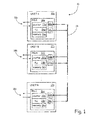
- FIG. 1 is a system diagram illustrating multiple units that each utilize a data phase-locked loop (PLL) for cross-channel data link (CCDL) communication.
- System 10 includes units 12a-12n and CCDL 14.
- Each of units 12a-12n include respective field-programmable gate arrays (FPGAs) 16a-16n, and primary input/output interfaces 18a-18n.
- Each FPGA 16a-16n includes respective data bit readers 20a-20n, counters 22a-22n, phase-locked loops (PLLs) 24a-24n, internal memory units 26a-26n, and transmitters 28a-28n.
- FPGAs 16a-16n may be implemented as any type of digital logic circuit.
- System 10 may be any electronic system that includes redundant units, such as critical systems onboard an aircraft.
- CCDL 14 includes one transmit line and one receive line for each pair of units. This allows each pair of units 12a-12n to communicate directly with the other units 12a-12n using a single input pin and a single output pin. For example, if system 10 includes three units, each unit will include two input pins and two output pins. Data may be edge-encoded using, for example, Manchester encoding as illustrated in FIG. 2 . Each unit transmits data onto CCDL 14 using transmitters 28a-28n. FPGA 16a encodes data for each of the other units 12b-12n and provides the encoded data to CCDL 14 through transmitter 28a.
- the data provided to CCDL 14 may be, for example, representative of data received, or data to be transmitted, by unit 12a on primary input/output interface 18a. This data may be provided to the other units 12b-12n so that the other units 12b-12n can verify their respective primary input or output.
- sensor data may be provided to units 12a-12n on input/output interface 18a-18n. This sensor data may be shared between units 12a-12n on CCDL 14 in order to, for example, verify the sensor data. If calculations are made on the sensor data, each unit 12a-12n may perform the calculation, and then share the result on CCDL 14 for verification prior to providing the result on input/output interface 18a-18n.
- Data bit reader 20a receives incoming data on CCDL 14 for unit 12a.
- This data is, for example, Manchester encoded.
- Manchester encoding represents data bits based upon transitions between "logic high” and “logic low” on CCDL 14. While the present embodiment is explained using Manchester encoding, any data encoding that utilizes transitions between "logic high” and “logic low” may be utilized.
- Counter 22a is utilized to provide over-sampling of the data on CCDL 14.
- counter 22a counts between a minimum count and an end-count at a sampling frequency. This frequency is based upon an oscillator of unit 12a. This oscillator may be internal or external to unit 12a. When the counter reaches the end-count, it loops back to the minimum count. The minimum and end-counts may be, for example, zero and five respectively. This provides six sampling iterations. Data is "over-sampled" on CCDL 14 by bit reader 20a at each iteration.
- bit reader 20a For example, if data is seen as “logic low” at iteration one, and is then seen as “logic high” at iteration two, then bit reader 20a reads a "binary zero" data bit. If data is seen as “logic high” at iteration one, and is then seen as “logic low” at iteration two, then bit reader 20a reads a "binary one" data bit. These data bits may then be stored, for example, within internal memory unit 26a.
- Memory unit 26a is, for example, static random-access memory (SRAM), dynamic random-access memory, flash memory, or any other type of electronic data storage.
- Data bit transitions are expected to be seen once for each set of six iterations of counter 22a. If the oscillator of unit 12a is properly synchronized to the oscillators of the other units 12b-12n, then data bit transitions should be seen, for example, sometime during the third iteration of counter 12a. This means that the data sampled by data bit reader 20a at counter value one should differ from the data sampled by data bit reader 20a at counter value two. Edge transitions not representative of data bits may also occur around the first or final iteration of each loop of the counter. For example, if two "binary ones" are sent consecutively, an edge transition will occur between data bits in order to allow for consecutive "logic high” to "logic low” data bit transitions. These edge transitions may be ignored by unit 12a.
- FIG. 2 is a chart illustrating sample data transmitted on CCDL 14 between units 12a-12n.
- data is transmitted on CCDL 14 as thirty-six bit data words.
- the first three “bits” are utilized as a sync pattern.
- the sync pattern is "logic low” for nine iterations of counter 22a, and then "logic high” for nine iterations. Therefore, if data bit reader 20a sees “logic low” data for an entire six iterations, unit 12 determines that a new data word is being sent. This is verified by seeing a bit transition from "logic low” to "logic high” during the next six iterations, and then seeing all "logic high” data for the following six iterations.
- data bit reader 20a For each incoming data bit that follows the sync pattern, data bit reader 20a expects to detect a data bit transition during the expected iteration of counter 22a which may be, for example, the third iteration. If a data bit transition is one iteration early or one iteration late, PLL 24a may record the early or late transition by, for example, setting a flag bit within unit 12a indicative of either a late or early data bit. If a subsequent data bit transition is also one iteration early or one iteration late, and the flag bit is already set, indicating that the previous data bit was also one iteration early or one iteration late, then PLL 24a adjusts the end-count value of counter 22a to compensate for the detected clock drift.
- PLL 24a subtracts one from the end-count value for this bit cycle. This adjustment allows data bits to once again be detected at the expected iteration. For the following data bit cycle, the end-count value is once again set to the normal value.
- the final bit in the data word is a parity bit. This provides further error protection for the incoming data.
- Unit 12a can perform, for example, a checksum on the received data using the parity bits to further ensure that there has been no data corruption. Although described for unit 12a, all units 12a-12n receive and verify data in a similar way.
- Prior art systems did not include PLLs 24a-24n and thus, required a higher oversample rate to ensure that clock drift did not cause data corruption.
- Data words also needed to be small in size with breaks between transmissions to further ensure that clock drift did not cause data loss or corruption.
- PLLs 24a-24n to account for clock drift, data words can be larger in size, can be continuously transmitted one after another, and can be transmitted at a higher rate. For example, if data can be transmitted at two megabits per second at a "12x" oversample rate, then the same data can be transmitted at four megabits per second for a "6x" oversample rate.
- FIGS. 1 and 2 is advantageous over alternative methods of CCDL communication such as universal asynchronous receiver/transmitters (UARTs), inter-integrated circuit (I2C), serial peripheral interface (SPI), small computer system interface (SCSI), or peripheral component interconnect (PCI) that may be implemented.
- UARTs universal asynchronous receiver/transmitters
- I2C inter-integrated circuit
- SPI serial peripheral interface
- SCSI small computer system interface
- PCI peripheral component interconnect
- These alternative interfaces may be slow, require several extra pins, or require complex drivers.
- a single transmit pin and single receive pin may be used to provide CCDL communication for each of the redundant units. This allows faster communication without the need for extra pins or complex communication protocols.
- FIG. 3 is a flowchart illustrating method 50 of receiving data in a system that utilizes cross-channel data link communication.
- counter 22a is set to zero and the end-count value for counter 22a is set to five.
- data is sampled by bit reader 20a on CCDL 14.
- step 58 it is determined at which counter iteration the data bit transition was seen. If the counter is currently equal to one, then the transition was seen one iteration earlier than expected, and method 50 proceeds to step 62. If the counter is currently equal to two, then the bit transition was seen at the expected iteration, and method 50 proceeds to step 66. If the counter is currently equal to three, then the transition was seen one iteration later than expected, and method 50 proceeds to step 64.
- step 62 the data bit transition was seen early, and it is determined if the previous data bit transition was also seen early. This may be determined, for example, by setting an indicator within FPGA 16a indicative of a previously seen early data bit. If the previous data bit was seen early, then method 50 proceeds to step 68. At step 68, PLL 24a updates the end-count value for counter 22a by subtracting one iteration. If the previous data bit was not seen early, then method 50 proceeds to step 66. An indicator, such as a data bit stored in FPGA 16a, is set to indicate that an early data bit transition was seen.
- step 64 the data bit transition was seen late, and it is determined if the previous data bit transition was also seen late. This may be determined, for example, by setting an indicator within FPGA 16a indicative of a previously seen late data bit. If the previous data bit was seen late, then method 50 proceeds to step 70. At step 70, PLL 24a updates the end-count value of counter 22a by adding one iteration. If the previous data bit was not seen late, then method 50 proceeds to step 66. An indicator, such as a data bit stored in FPGA 16a, is set to indicate that a late data bit transition was seen.
- step 66 the data seen for the data bit transition is recorded.
- the data bit is recorded as a "logic one" or “logic zero” depending upon the chosen data encoding for the data communicated on CCDL 14.
- step 60 it is determined whether or not counter 22a is on its final iteration by comparing the current iteration to the end-count value. If it is, then method 50 returns to step 52 and resets the counter to zero and the end-count value to five for the next data bit. If counter 22a is not on its final iteration, then method 50 proceeds to step 72 and the counter is moved to the next iteration for the next clock cycle. Method 50 then returns to step 54 to sample data for the next iteration. Method 50 continues for the duration data transmission on CCDL 14. Although not shown, it is understood that detection of a sync pattern such as the one illustrated in FIG. 2 may be included within method 50.
- a data communication system includes, among other things: a first unit that receives edge-encoded data from a data link.
- the first unit includes, among other things: a first counter, a first data bit reader, and a first phase-locked loop.
- the first counter counts at a sampling frequency from a minimum value to an end-count value.
- the first data bit reader is connected to receive the edge-encoded data.
- the first data bit reader samples the edge-encoded data at the sampling frequency to detect data bits of the edge-encoded data.
- the first phase-locked loop updates the end-count value if consecutive bits of the data bits are detected prior to an expected iteration of the first counter, and updates the end-count value if consecutive bits of the data bits are detected later than the expected iteration of the first counter.
- the system of the preceding paragraph can optionally include, additionally and/or alternatively, any one or more of the following features, configurations and/or additional components:
- a further embodiment of the foregoing system wherein the first phase-locked loop subtracts one iteration from the end-count value upon detection of consecutive data bits one iteration prior to the expected iteration.
- edge-encoded data is Manchester encoded and includes a three bit sync pattern, thirty-two data bits, and a parity bit.
- a further embodiment of any of the foregoing systems further including a second unit that communicates with the first unit over the data link, wherein the second unit includes a second data bit reader, a second counter, and a second phase-locked loop, and wherein the first unit includes a first data transmitter for communicating edge-encoded data to the second unit, and wherein the second unit includes a second data transmitter for communicating the edge-encoded data to the first unit.
- a method of receiving edge-encoded data communicated on a data link includes, among other things: incrementing a counter at a sampling frequency, wherein the counter counts from a minimum value to an end-count value; sampling data, using a data bit reader, at each iteration of the counter; detecting data bits, using the data bit reader, of the edge-encoded data; adjusting the end-count value using a phase-locked loop if two consecutive data bits are each detected at iterations earlier than an expected iteration of the counter; and adjusting the end-count value using the phase-locked loop if two consecutive data bits are detected at iterations later than the expected iteration of the counter.
- the method of the preceding paragraph can optionally include, additionally and/or alternatively, any one or more of the following features, configurations and/or additional components:
- adjusting the end-count value using the phase-locked loop if two consecutive data bits are detected each at iterations earlier than the expected iteration comprises subtracting one iteration from the end-count value if the two consecutive data bits are each detected one iteration earlier than the expected iteration.
- adjusting the end-count value using the phase-locked loop if two consecutive data bits are each detected at iterations later than the expected iteration comprises adding one iteration to the end-count value if the two consecutive data bits are each detected one iteration later than the expected iteration.
- edge-encoded data is Manchester encoded and includes a three bit sync pattern, thirty-two data bits, and a parity bit.
- incrementing the counter comprises, for each data bit, looping the counter every six iterations, and wherein the expected iteration of the counter is the third iteration of each loop.
Landscapes
- Engineering & Computer Science (AREA)
- Computer Networks & Wireless Communication (AREA)
- Signal Processing (AREA)
- Physics & Mathematics (AREA)
- Spectroscopy & Molecular Physics (AREA)
- Stabilization Of Oscillater, Synchronisation, Frequency Synthesizers (AREA)
- Synchronisation In Digital Transmission Systems (AREA)
- Dc Digital Transmission (AREA)
Abstract
A data communication system includes a unit 12 that receives edge-encoded data from a data link. The unit includes a counter 22, a data bit reader 20, and a phase-locked loop 24. The counter counts at a sampling frequency between a minimum value and an end-count value. The data bit reader is connected to receive the edge-encoded data. The data bit reader samples the edge-encoded data at the sampling frequency to detect data bits of the edge-encoded data. The phase-locked loop updates the end-count value if consecutive bits of the data bits are detected prior to an expected iteration of the counter. The phase-locked loop also updates the end-count value if consecutive bits of the data bits are detected later than the expected iteration of the first counter.
Description
- The present invention is related to data communication, and in particular to a system and method for cross-channel data link communication.
- In critical systems, such as those onboard aircraft, redundant units are often utilized to protect against failures and verify input and output data. The redundant units may communicate shared data with one another in order to verify the integrity of the data. These systems are often asynchronous systems in which each unit includes its own oscillator. Because of this, in order to ensure data integrity, data must be sampled at a high oversample rate. This limits the speed at which data can be communicated between the units. It is desirable to limit the oversample rate in order to provide greater speed for the data communication between the redundant units.
- A data communication system includes a unit that receives edge-encoded data from a data link. The unit includes a counter, a data bit reader, and a phase-locked loop. The counter counts at a sampling frequency from a minimum value and an end-count value. The data bit reader is connected to receive the edge-encoded data. The data bit reader samples the edge-encoded data at the sampling frequency to detect data bits of the edge-encoded data. The phase-locked loop updates the end-count value if consecutive bits of the data bits are detected prior to an expected iteration of the counter. The phase-locked loop also updates the end-count value if consecutive bits of the data bits are detected later than the expected iteration of the first counter.
-
-
FIG. 1 is a system diagram illustrating multiple units each utilizing a phase-locked loop for cross-channel data link communication. -
FIG. 2 is a chart illustrating an embodiment of data transmitted on a cross-channel data link. -
FIG. 3 is a flowchart illustrating a method of receiving data in a system that utilizes cross-channel data link communication. - A system and method for communicating data on a cross-channel data link includes multiple redundant units that each include a data bit reader, a counter, and a phase-locked loop. The units each include processing units such as, for example, field programmable gate-arrays (FPGAs). The units are connected to one another through a cross-channel data link (CCDL). Each FPGA includes a data transmitter that produces edge-encoded data on the CCDL for the other units, and a data bit reader that receives the edge-encoded data from the other units on the CCDL. Each FPGA also includes a counter and a phase-locked loop (PLL). For each unit, the counter increments at an oversample frequency and loops each time the counter reaches an end-count value. The data bit reader samples data at each iteration of the counter. The data on the CCDL is encoded using, for example, Manchester encoding and thus, data bits are received by detecting an edge transition on the CCDL. When synchronized, the edge transitions that represent data bits are detected at an expected iteration of the counter such as, for example, the third iteration. If data bits are detected earlier than expected or later than expected for consecutive data bits, the PLL adjusts the end-count value for the current data bit accordingly so that the following data bits are once again detected at the expected iteration. By utilizing the PLLs in this way, clock drift between the units may be accounted for. This allows the data to be oversampled at a lower rate than the prior art, which in turn allows the data to be transmitted at a faster rate.
-
FIG. 1 is a system diagram illustrating multiple units that each utilize a data phase-locked loop (PLL) for cross-channel data link (CCDL) communication.System 10 includesunits 12a-12n andCCDL 14. Each ofunits 12a-12n include respective field-programmable gate arrays (FPGAs) 16a-16n, and primary input/output interfaces 18a-18n. EachFPGA 16a-16n includes respectivedata bit readers 20a-20n,counters 22a-22n, phase-locked loops (PLLs) 24a-24n, internal memory units 26a-26n, andtransmitters 28a-28n. In other embodiments,FPGAs 16a-16n may be implemented as any type of digital logic circuit.System 10 may be any electronic system that includes redundant units, such as critical systems onboard an aircraft. - CCDL 14 includes one transmit line and one receive line for each pair of units. This allows each pair of
units 12a-12n to communicate directly with theother units 12a-12n using a single input pin and a single output pin. For example, ifsystem 10 includes three units, each unit will include two input pins and two output pins. Data may be edge-encoded using, for example, Manchester encoding as illustrated inFIG. 2 . Each unit transmits data ontoCCDL 14 usingtransmitters 28a-28n.FPGA 16a encodes data for each of theother units 12b-12n and provides the encoded data toCCDL 14 throughtransmitter 28a. The data provided toCCDL 14 may be, for example, representative of data received, or data to be transmitted, byunit 12a on primary input/output interface 18a. This data may be provided to theother units 12b-12n so that theother units 12b-12n can verify their respective primary input or output. For example, sensor data may be provided tounits 12a-12n on input/output interface 18a-18n. This sensor data may be shared betweenunits 12a-12n onCCDL 14 in order to, for example, verify the sensor data. If calculations are made on the sensor data, eachunit 12a-12n may perform the calculation, and then share the result onCCDL 14 for verification prior to providing the result on input/output interface 18a-18n. -
Data bit reader 20a receives incoming data onCCDL 14 forunit 12a. This data is, for example, Manchester encoded. Manchester encoding represents data bits based upon transitions between "logic high" and "logic low" onCCDL 14. While the present embodiment is explained using Manchester encoding, any data encoding that utilizes transitions between "logic high" and "logic low" may be utilized. -
Counter 22a is utilized to provide over-sampling of the data onCCDL 14. Forunit 12a,counter 22a counts between a minimum count and an end-count at a sampling frequency. This frequency is based upon an oscillator ofunit 12a. This oscillator may be internal or external tounit 12a. When the counter reaches the end-count, it loops back to the minimum count. The minimum and end-counts may be, for example, zero and five respectively. This provides six sampling iterations. Data is "over-sampled" onCCDL 14 bybit reader 20a at each iteration. For example, if data is seen as "logic low" at iteration one, and is then seen as "logic high" at iteration two, thenbit reader 20a reads a "binary zero" data bit. If data is seen as "logic high" at iteration one, and is then seen as "logic low" at iteration two, thenbit reader 20a reads a "binary one" data bit. These data bits may then be stored, for example, within internal memory unit 26a. Memory unit 26a is, for example, static random-access memory (SRAM), dynamic random-access memory, flash memory, or any other type of electronic data storage. - Data bit transitions are expected to be seen once for each set of six iterations of
counter 22a. If the oscillator ofunit 12a is properly synchronized to the oscillators of theother units 12b-12n, then data bit transitions should be seen, for example, sometime during the third iteration ofcounter 12a. This means that the data sampled by data bitreader 20a at counter value one should differ from the data sampled by data bitreader 20a at counter value two. Edge transitions not representative of data bits may also occur around the first or final iteration of each loop of the counter. For example, if two "binary ones" are sent consecutively, an edge transition will occur between data bits in order to allow for consecutive "logic high" to "logic low" data bit transitions. These edge transitions may be ignored byunit 12a. - With continued reference to
FIG. 1 ,FIG. 2 is a chart illustrating sample data transmitted onCCDL 14 betweenunits 12a-12n. In the embodiment illustrated inFIG. 2 , data is transmitted onCCDL 14 as thirty-six bit data words. The first three "bits" are utilized as a sync pattern. The sync pattern is "logic low" for nine iterations ofcounter 22a, and then "logic high" for nine iterations. Therefore, if data bitreader 20a sees "logic low" data for an entire six iterations, unit 12 determines that a new data word is being sent. This is verified by seeing a bit transition from "logic low" to "logic high" during the next six iterations, and then seeing all "logic high" data for the following six iterations. - For each incoming data bit that follows the sync pattern, data bit
reader 20a expects to detect a data bit transition during the expected iteration ofcounter 22a which may be, for example, the third iteration. If a data bit transition is one iteration early or one iteration late, PLL 24a may record the early or late transition by, for example, setting a flag bit withinunit 12a indicative of either a late or early data bit. If a subsequent data bit transition is also one iteration early or one iteration late, and the flag bit is already set, indicating that the previous data bit was also one iteration early or one iteration late, then PLL 24a adjusts the end-count value ofcounter 22a to compensate for the detected clock drift. For example, if the expected iteration is two, and the data bit transition for data bit four is seen at counter iteration one, and then the data bit transition for data bit five is also seen at counter iteration one, then PLL 24a subtracts one from the end-count value for this bit cycle. This adjustment allows data bits to once again be detected at the expected iteration. For the following data bit cycle, the end-count value is once again set to the normal value. - The final bit in the data word is a parity bit. This provides further error protection for the incoming data.
Unit 12a can perform, for example, a checksum on the received data using the parity bits to further ensure that there has been no data corruption. Although described forunit 12a, allunits 12a-12n receive and verify data in a similar way. - Prior art systems did not include PLLs 24a-24n and thus, required a higher oversample rate to ensure that clock drift did not cause data corruption. Data words also needed to be small in size with breaks between transmissions to further ensure that clock drift did not cause data loss or corruption. By introducing PLLs 24a-24n to account for clock drift, data words can be larger in size, can be continuously transmitted one after another, and can be transmitted at a higher rate. For example, if data can be transmitted at two megabits per second at a "12x" oversample rate, then the same data can be transmitted at four megabits per second for a "6x" oversample rate.
- The embodiment illustrated in
FIGS. 1 and2 is advantageous over alternative methods of CCDL communication such as universal asynchronous receiver/transmitters (UARTs), inter-integrated circuit (I2C), serial peripheral interface (SPI), small computer system interface (SCSI), or peripheral component interconnect (PCI) that may be implemented. These alternative interfaces may be slow, require several extra pins, or require complex drivers. By using a PLL with edge-encoded data, a single transmit pin and single receive pin may be used to provide CCDL communication for each of the redundant units. This allows faster communication without the need for extra pins or complex communication protocols. - With continued reference to
FIG. 1 ,FIG. 3 is aflowchart illustrating method 50 of receiving data in a system that utilizes cross-channel data link communication. Atstep 52,counter 22a is set to zero and the end-count value forcounter 22a is set to five. Atstep 54, data is sampled bybit reader 20a onCCDL 14. Atstep 56, it is determined if a data bit transition is seen onCCDL 14. This may be accomplished by comparing the previously sampled data with the currently sampled data. If the data differs, then a data bit transition has been detected. If a data bit transition has been detected, thenmethod 50 proceeds to step 58. If a data bit transition has not been detected, thenmethod 50 proceeds to step 60. - At
step 58, it is determined at which counter iteration the data bit transition was seen. If the counter is currently equal to one, then the transition was seen one iteration earlier than expected, andmethod 50 proceeds to step 62. If the counter is currently equal to two, then the bit transition was seen at the expected iteration, andmethod 50 proceeds to step 66. If the counter is currently equal to three, then the transition was seen one iteration later than expected, andmethod 50 proceeds to step 64. - At
step 62, the data bit transition was seen early, and it is determined if the previous data bit transition was also seen early. This may be determined, for example, by setting an indicator withinFPGA 16a indicative of a previously seen early data bit. If the previous data bit was seen early, thenmethod 50 proceeds to step 68. Atstep 68, PLL 24a updates the end-count value forcounter 22a by subtracting one iteration. If the previous data bit was not seen early, thenmethod 50 proceeds to step 66. An indicator, such as a data bit stored inFPGA 16a, is set to indicate that an early data bit transition was seen. - At
step 64, the data bit transition was seen late, and it is determined if the previous data bit transition was also seen late. This may be determined, for example, by setting an indicator withinFPGA 16a indicative of a previously seen late data bit. If the previous data bit was seen late, thenmethod 50 proceeds to step 70. Atstep 70, PLL 24a updates the end-count value ofcounter 22a by adding one iteration. If the previous data bit was not seen late, thenmethod 50 proceeds to step 66. An indicator, such as a data bit stored inFPGA 16a, is set to indicate that a late data bit transition was seen. - At
step 66, the data seen for the data bit transition is recorded. The data bit is recorded as a "logic one" or "logic zero" depending upon the chosen data encoding for the data communicated onCCDL 14. Atstep 60, it is determined whether or not counter 22a is on its final iteration by comparing the current iteration to the end-count value. If it is, thenmethod 50 returns to step 52 and resets the counter to zero and the end-count value to five for the next data bit. Ifcounter 22a is not on its final iteration, thenmethod 50 proceeds to step 72 and the counter is moved to the next iteration for the next clock cycle.Method 50 then returns to step 54 to sample data for the next iteration.Method 50 continues for the duration data transmission onCCDL 14. Although not shown, it is understood that detection of a sync pattern such as the one illustrated inFIG. 2 may be included withinmethod 50. - The following are non-exclusive descriptions of possible embodiments of the present invention.
- A data communication system includes, among other things: a first unit that receives edge-encoded data from a data link. The first unit includes, among other things: a first counter, a first data bit reader, and a first phase-locked loop. The first counter counts at a sampling frequency from a minimum value to an end-count value. The first data bit reader is connected to receive the edge-encoded data. The first data bit reader samples the edge-encoded data at the sampling frequency to detect data bits of the edge-encoded data. The first phase-locked loop updates the end-count value if consecutive bits of the data bits are detected prior to an expected iteration of the first counter, and updates the end-count value if consecutive bits of the data bits are detected later than the expected iteration of the first counter.
- The system of the preceding paragraph can optionally include, additionally and/or alternatively, any one or more of the following features, configurations and/or additional components:
- A further embodiment of the foregoing system, wherein the first phase-locked loop subtracts one iteration from the end-count value upon detection of consecutive data bits one iteration prior to the expected iteration.
- A further embodiment of any of the foregoing systems, wherein the first phase-locked loop adds one iteration to the end-count value upon detection of consecutive data bits one iteration after the expected iteration.
- A further embodiment of any of the foregoing systems, wherein the first counter loops for six iterations, and the expected iteration is the third iteration.
- A further embodiment of any of the foregoing systems, wherein the edge-encoded data is Manchester encoded and includes a three bit sync pattern, thirty-two data bits, and a parity bit.
- A further embodiment of any of the foregoing systems, further including a second unit that communicates with the first unit over the data link, wherein the second unit includes a second data bit reader, a second counter, and a second phase-locked loop, and wherein the first unit includes a first data transmitter for communicating edge-encoded data to the second unit, and wherein the second unit includes a second data transmitter for communicating the edge-encoded data to the first unit.
- A method of receiving edge-encoded data communicated on a data link includes, among other things: incrementing a counter at a sampling frequency, wherein the counter counts from a minimum value to an end-count value; sampling data, using a data bit reader, at each iteration of the counter; detecting data bits, using the data bit reader, of the edge-encoded data; adjusting the end-count value using a phase-locked loop if two consecutive data bits are each detected at iterations earlier than an expected iteration of the counter; and adjusting the end-count value using the phase-locked loop if two consecutive data bits are detected at iterations later than the expected iteration of the counter.
- The method of the preceding paragraph can optionally include, additionally and/or alternatively, any one or more of the following features, configurations and/or additional components:
- A further embodiment of the foregoing method, wherein adjusting the end-count value using the phase-locked loop if two consecutive data bits are detected each at iterations earlier than the expected iteration comprises subtracting one iteration from the end-count value if the two consecutive data bits are each detected one iteration earlier than the expected iteration.
- A further embodiment of any of the foregoing methods, wherein adjusting the end-count value using the phase-locked loop if two consecutive data bits are each detected at iterations later than the expected iteration comprises adding one iteration to the end-count value if the two consecutive data bits are each detected one iteration later than the expected iteration.
- A further embodiment of any of the foregoing methods, wherein the edge-encoded data is Manchester encoded and includes a three bit sync pattern, thirty-two data bits, and a parity bit.
- A further embodiment of any of the foregoing methods, wherein incrementing the counter comprises, for each data bit, looping the counter every six iterations, and wherein the expected iteration of the counter is the third iteration of each loop.
- While the invention has been described with reference to an exemplary embodiment(s), it will be understood by those skilled in the art that various changes may be made and equivalents may be substituted for elements thereof without departing from the scope of the invention as defined by the claims. In addition, many modifications may be made to adapt a particular situation or material to the teachings of the invention without departing from the scope thereof. Therefore, it is intended that the invention not be limited to the particular embodiment(s) disclosed, but that the invention will include all embodiments falling within the scope of the appended claims.
Claims (12)
- A data communication system comprising:a first unit (12a) that receives edge-encoded data from a data link, wherein the first unit comprises:a first counter (22a) that counts at a sampling frequency from a minimum value to an end-count value;a first data bit reader (20a) connected to receive the edge-encoded data, wherein the first data bit reader samples the edge-encoded data at the sampling frequency to detect data bits of the edge-encoded data; anda first phase-locked loop (24a) that updates the end-count value if consecutive bits of the data bits are detected prior to an expected iteration of the first counter, and that updates the end-count value if consecutive bits of the data bits are detected later than the expected iteration of the first counter.
- The system of claim 1, wherein the first phase-locked loop subtracts one iteration from the end-count value upon detection of consecutive data bits one iteration prior to the expected iteration.
- The system of claim 1, wherein the first phase-locked loop adds one iteration to the end-count value upon detection of consecutive data bits one iteration after the expected iteration.
- The system of claim 1, wherein the first counter loops for six iterations, and the expected iteration is the third iteration.
- The system of claim 1, wherein the edge-encoded data is Manchester encoded and includes a three bit sync pattern, thirty-two data bits, and a parity bit.
- The system of claim 1, further comprising a second unit (12b) that communicates with the first unit over the data link, wherein the second unit includes a second data bit reader (20b), a second counter (22b), and a second phase-locked loop (24b), and wherein the first unit includes a first data transmitter for communicating edge-encoded data to the second unit, and wherein the second unit includes a second data transmitter for communicating the edge-encoded data to the first unit.
- The system of claim 1, wherein the first unit further comprises a field programmable gate-array, and wherein the field programmable gate-array comprises the first data bit reader, the first counter, the first phase-locked loop, and an internal memory that stores the edge-encoded data.
- A method of receiving edge-encoded data communicated on a data link, the method comprising:incrementing a counter at a sampling frequency, wherein the counter counts between a minimum value and an end-count value;sampling data, using a data bit reader, at each iteration of the counter;detecting data bits, using the data bit reader, of the edge-encoded data;adjusting the end-count value using a phase-locked loop if two consecutive data bits are each detected at iterations earlier than an expected iteration of the counter; andadjusting the end-count value using the phase-locked loop if two consecutive data bits are detected at iterations later than the expected iteration of the counter.
- The method of claim 8, wherein adjusting the end-count value using the phase-locked loop if two consecutive data bits are detected each at iterations earlier than the expected iteration comprises subtracting one iteration from the end-count value if the two consecutive data bits are each detected one iteration earlier than the expected iteration.
- The method of claim 8, wherein adjusting the end-count value using the phase-locked loop if two consecutive data bits are each detected at iterations later than the expected iteration comprises adding one iteration to the end-count value if the two consecutive data bits are each detected one iteration later than the expected iteration.
- The method of claim 8, wherein the edge-encoded data is Manchester encoded and includes a three bit sync pattern, thirty-two data bits, and a parity bit.
- The method of claim 8, wherein incrementing the counter comprises, for each data bit, looping the counter every six iterations, and wherein the expected iteration of the counter is the third iteration of each loop.
Applications Claiming Priority (1)
| Application Number | Priority Date | Filing Date | Title |
|---|---|---|---|
| US14/153,294 US9166775B2 (en) | 2014-01-13 | 2014-01-13 | Cross-channel data communication with data phase-locked loop |
Publications (1)
| Publication Number | Publication Date |
|---|---|
| EP2894809A1 true EP2894809A1 (en) | 2015-07-15 |
Family
ID=52339026
Family Applications (1)
| Application Number | Title | Priority Date | Filing Date |
|---|---|---|---|
| EP15150792.8A Withdrawn EP2894809A1 (en) | 2014-01-13 | 2015-01-12 | Synchronization of edge encoded data by a digital phase-locked loop |
Country Status (2)
| Country | Link |
|---|---|
| US (1) | US9166775B2 (en) |
| EP (1) | EP2894809A1 (en) |
Citations (1)
| Publication number | Priority date | Publication date | Assignee | Title |
|---|---|---|---|---|
| US5168511A (en) * | 1990-10-22 | 1992-12-01 | Berkeley Varitronics Systems, Inc. | Manchester data recorder with synchronously adjustable clock |
Family Cites Families (11)
| Publication number | Priority date | Publication date | Assignee | Title |
|---|---|---|---|---|
| US3840821A (en) * | 1967-07-27 | 1974-10-08 | Sperry Rand Corp | Phase lock loop with sampling techniques for regenerating clock signal associated with data input signals |
| US5271040A (en) * | 1991-12-20 | 1993-12-14 | Vlsi Technology, Inc. | Phase detector circuit |
| US5952888A (en) * | 1998-03-25 | 1999-09-14 | Cypress Semiconductor Corp. | Roving range control to limit receive PLL frequency of operation |
| US6901127B1 (en) * | 2000-04-26 | 2005-05-31 | Sigmatel, Inc. | Method and apparatus for data recovery |
| JP2006238309A (en) * | 2005-02-28 | 2006-09-07 | Kawasaki Microelectronics Kk | Semiconductor integrated circuit |
| JP2006303663A (en) * | 2005-04-18 | 2006-11-02 | Nec Electronics Corp | Optically coupled insulation circuit |
| JP5508662B2 (en) * | 2007-01-12 | 2014-06-04 | 株式会社半導体エネルギー研究所 | Display device |
| JP5747831B2 (en) * | 2012-02-07 | 2015-07-15 | 株式会社リコー | MOTOR CONTROL DEVICE, CONVEYING DEVICE, IMAGE FORMING DEVICE, MOTOR CONTROL METHOD, AND PROGRAM |
| US20140225635A1 (en) * | 2013-02-11 | 2014-08-14 | Qualcomm Incorporated | All-digital phase locked loop self test system |
| JP5975912B2 (en) * | 2013-03-18 | 2016-08-23 | ルネサスエレクトロニクス株式会社 | High frequency signal processor |
| US9054941B2 (en) * | 2013-07-18 | 2015-06-09 | Rf Micro Devices, Inc. | Clock and data recovery using dual manchester encoded data streams |
-
2014
- 2014-01-13 US US14/153,294 patent/US9166775B2/en active Active
-
2015
- 2015-01-12 EP EP15150792.8A patent/EP2894809A1/en not_active Withdrawn
Patent Citations (1)
| Publication number | Priority date | Publication date | Assignee | Title |
|---|---|---|---|---|
| US5168511A (en) * | 1990-10-22 | 1992-12-01 | Berkeley Varitronics Systems, Inc. | Manchester data recorder with synchronously adjustable clock |
Also Published As
| Publication number | Publication date |
|---|---|
| US9166775B2 (en) | 2015-10-20 |
| US20150200769A1 (en) | 2015-07-16 |
Similar Documents
| Publication | Publication Date | Title |
|---|---|---|
| EP2976866B1 (en) | Timestamp correction in a multi-lane communication link with skew | |
| US11671194B2 (en) | Technologies for high-precision timestamping of packets | |
| RU2606062C2 (en) | Method and device for testing correct function of serial data transmission | |
| EP2898632B1 (en) | Controller area network with flexible data-rate | |
| US20160286010A1 (en) | Filter Or Bridge For Communications Between CAN And CAN-FD Protocol Modules | |
| US10396921B2 (en) | Multi-lane synchronization method, synchronization apparatus and system, and computer storage medium | |
| US9268888B1 (en) | Latency computation circuitry | |
| US20200092043A1 (en) | Data transmission method, device, computer-readable storage medium, and system | |
| US8995596B1 (en) | Techniques for calibrating a clock signal | |
| KR102817586B1 (en) | In-vehicle communication device and time synchronization method thereof | |
| US9891653B2 (en) | Techniques for clock rate changes during data rate changes in an integrated circuit (IC) | |
| KR102204954B1 (en) | Can controller and method for transmission of data using the same | |
| US12328203B2 (en) | Low clock rate MIL-STD-1553B decoder for field programmable gate arrays | |
| US10969822B2 (en) | Reducing time of day latency variation in a multi processor system | |
| US9921899B2 (en) | Monitoring serial link errors | |
| US9166775B2 (en) | Cross-channel data communication with data phase-locked loop | |
| US8880758B2 (en) | Harmonic decimation of real time data for unique word (or sync cell) acquisition in a limited processing environment | |
| US20160156431A1 (en) | High speed data transmission methods and systems upon error detection | |
| US10324491B2 (en) | Reducing time of day latency variation in a multi-processor system | |
| CN112260814B (en) | Data phase correction method for high-speed serial communication, electronic device, and storage medium | |
| US7694176B2 (en) | Fault-tolerant computer and method of controlling same | |
| US9910818B2 (en) | Serdes interface architecture for multi-processor systems | |
| US10467171B2 (en) | Detecting the drift of the data valid window in a transaction | |
| EP3349399B1 (en) | Message dropout minimization when transporting isochronous packets across a plesiochronous boundary | |
| CN115766892A (en) | Data transmitting method and receiving method |
Legal Events
| Date | Code | Title | Description |
|---|---|---|---|
| PUAI | Public reference made under article 153(3) epc to a published international application that has entered the european phase |
Free format text: ORIGINAL CODE: 0009012 |
|
| 17P | Request for examination filed |
Effective date: 20150112 |
|
| AK | Designated contracting states |
Kind code of ref document: A1 Designated state(s): AL AT BE BG CH CY CZ DE DK EE ES FI FR GB GR HR HU IE IS IT LI LT LU LV MC MK MT NL NO PL PT RO RS SE SI SK SM TR |
|
| AX | Request for extension of the european patent |
Extension state: BA ME |
|
| STAA | Information on the status of an ep patent application or granted ep patent |
Free format text: STATUS: THE APPLICATION IS DEEMED TO BE WITHDRAWN |
|
| 18D | Application deemed to be withdrawn |
Effective date: 20160116 |