EP2894766A1 - Fluid pump - Google Patents
Fluid pump Download PDFInfo
- Publication number
- EP2894766A1 EP2894766A1 EP14164761.0A EP14164761A EP2894766A1 EP 2894766 A1 EP2894766 A1 EP 2894766A1 EP 14164761 A EP14164761 A EP 14164761A EP 2894766 A1 EP2894766 A1 EP 2894766A1
- Authority
- EP
- European Patent Office
- Prior art keywords
- fluid pump
- outlet
- impeller
- section
- base section
- Prior art date
- Legal status (The legal status is an assumption and is not a legal conclusion. Google has not performed a legal analysis and makes no representation as to the accuracy of the status listed.)
- Granted
Links
Images



Classifications
-
- F—MECHANICAL ENGINEERING; LIGHTING; HEATING; WEAPONS; BLASTING
- F04—POSITIVE - DISPLACEMENT MACHINES FOR LIQUIDS; PUMPS FOR LIQUIDS OR ELASTIC FLUIDS
- F04D—NON-POSITIVE-DISPLACEMENT PUMPS
- F04D13/00—Pumping installations or systems
- F04D13/02—Units comprising pumps and their driving means
- F04D13/06—Units comprising pumps and their driving means the pump being electrically driven
-
- F—MECHANICAL ENGINEERING; LIGHTING; HEATING; WEAPONS; BLASTING
- F04—POSITIVE - DISPLACEMENT MACHINES FOR LIQUIDS; PUMPS FOR LIQUIDS OR ELASTIC FLUIDS
- F04D—NON-POSITIVE-DISPLACEMENT PUMPS
- F04D29/00—Details, component parts, or accessories
- F04D29/04—Shafts or bearings, or assemblies thereof
- F04D29/046—Bearings
-
- F—MECHANICAL ENGINEERING; LIGHTING; HEATING; WEAPONS; BLASTING
- F04—POSITIVE - DISPLACEMENT MACHINES FOR LIQUIDS; PUMPS FOR LIQUIDS OR ELASTIC FLUIDS
- F04D—NON-POSITIVE-DISPLACEMENT PUMPS
- F04D29/00—Details, component parts, or accessories
- F04D29/60—Mounting; Assembling; Disassembling
- F04D29/62—Mounting; Assembling; Disassembling of radial or helico-centrifugal pumps
- F04D29/628—Mounting; Assembling; Disassembling of radial or helico-centrifugal pumps especially adapted for liquid pumps
-
- F—MECHANICAL ENGINEERING; LIGHTING; HEATING; WEAPONS; BLASTING
- F04—POSITIVE - DISPLACEMENT MACHINES FOR LIQUIDS; PUMPS FOR LIQUIDS OR ELASTIC FLUIDS
- F04D—NON-POSITIVE-DISPLACEMENT PUMPS
- F04D5/00—Pumps with circumferential or transverse flow
- F04D5/002—Regenerative pumps
-
- H—ELECTRICITY
- H02—GENERATION; CONVERSION OR DISTRIBUTION OF ELECTRIC POWER
- H02K—DYNAMO-ELECTRIC MACHINES
- H02K1/00—Details of the magnetic circuit
- H02K1/06—Details of the magnetic circuit characterised by the shape, form or construction
- H02K1/12—Stationary parts of the magnetic circuit
- H02K1/17—Stator cores with permanent magnets
-
- H—ELECTRICITY
- H02—GENERATION; CONVERSION OR DISTRIBUTION OF ELECTRIC POWER
- H02K—DYNAMO-ELECTRIC MACHINES
- H02K23/00—DC commutator motors or generators having mechanical commutator; Universal AC/DC commutator motors
- H02K23/02—DC commutator motors or generators having mechanical commutator; Universal AC/DC commutator motors characterised by arrangement for exciting
- H02K23/04—DC commutator motors or generators having mechanical commutator; Universal AC/DC commutator motors characterised by arrangement for exciting having permanent magnet excitation
-
- H—ELECTRICITY
- H02—GENERATION; CONVERSION OR DISTRIBUTION OF ELECTRIC POWER
- H02K—DYNAMO-ELECTRIC MACHINES
- H02K5/00—Casings; Enclosures; Supports
- H02K5/04—Casings or enclosures characterised by the shape, form or construction thereof
- H02K5/15—Mounting arrangements for bearing-shields or end plates
-
- H—ELECTRICITY
- H02—GENERATION; CONVERSION OR DISTRIBUTION OF ELECTRIC POWER
- H02K—DYNAMO-ELECTRIC MACHINES
- H02K5/00—Casings; Enclosures; Supports
- H02K5/04—Casings or enclosures characterised by the shape, form or construction thereof
- H02K5/16—Means for supporting bearings, e.g. insulating supports or means for fitting bearings in the bearing-shields
- H02K5/167—Means for supporting bearings, e.g. insulating supports or means for fitting bearings in the bearing-shields using sliding-contact or spherical cap bearings
- H02K5/1672—Means for supporting bearings, e.g. insulating supports or means for fitting bearings in the bearing-shields using sliding-contact or spherical cap bearings radially supporting the rotary shaft at both ends of the rotor
-
- H—ELECTRICITY
- H02—GENERATION; CONVERSION OR DISTRIBUTION OF ELECTRIC POWER
- H02K—DYNAMO-ELECTRIC MACHINES
- H02K5/00—Casings; Enclosures; Supports
- H02K5/04—Casings or enclosures characterised by the shape, form or construction thereof
- H02K5/14—Means for supporting or protecting brushes or brush holders
- H02K5/143—Means for supporting or protecting brushes or brush holders for cooperation with commutators
- H02K5/148—Slidably supported brushes
Definitions
- the present invention relates to a fluid pump; more particularly to a fuel pump; and even more particularly to a fuel pump with an electric motor with a motor frame that defines an upper bushing and maintains a coaxial relationship of a lower bushing with the upper bushing.
- Fluid pumps and more particularly fuel pumps for pumping fuel, for example, from a fuel tank of a motor vehicle to an internal combustion engine of the motor vehicle, are known.
- United States Patent Application Publication No. US 2010/0047090 A1 shows one type of fuel pump which includes an impeller. An inlet plate is disposed adjacent to one face of the impeller and an outlet plate is disposed adjacent to the face of the impeller that is opposite the inlet plate.
- An electric motor of the fuel pump includes a shaft which is coupled to the impeller. One end of the shaft is supported radially by a lower bushing formed integrally with the outlet plate while the other end of the shaft is supported by an upper bushing formed in a base of the motor.
- the radial position of the lower bearing is determined by the outside diameter of the outlet plate and the inside diameter of a housing while the radial position of the upper bushing is determined by the outside diameter of the base of the motor and the inside diameter of the housing. Since separate tooling is used to manufacture the housing, the base of the motor and the outlet plate, it may be difficult to maintain a sufficient coaxial relationship between the upper bushing and the lower bushing.
- a fluid pump includes an inlet for introducing fluid into the fluid pump and an outlet for discharging fluid from the fluid pump.
- the fluid pump also includes a motor having a shaft with an upper end and lower end that rotates about an axis.
- the fluid pump also includes a motor frame having a top section, a base section, and a plurality of legs that axially separate the top section and the base section.
- the fluid pump also includes a lower bushing for radially supporting the lower end of the shaft.
- the top section defines an upper bushing therein for radially supporting the upper end of the shaft and the base section maintains a coaxial relationship between the lower bushing and the upper bushing.
- the fluid pump further comprises an impeller having an array of blades radially surrounding the axis wherein the impeller is rotatable by the shaft of the motor wherein rotation of the impeller pumps fluid from the inlet to the outlet.
- the fluid pump further comprises an inlet plate adjacent to the impeller and includes the inlet wherein the inlet plate includes an inlet plate flow channel aligned with the array of blades; and an outlet plate adjacent to the impeller on the side of the impeller that is opposite to the inlet plate wherein the outlet plate has an outlet passage in fluid communication with the outlet and an outlet plate flow channel aligned with the array of blades.
- the outlet plate defines the lower bushing.
- the plurality of legs define motor frame openings spaced circumferentially therebetween.
- the fluid pump further comprises a plurality of magnets wherein each one of the plurality of magnets is disposed within a respective one of the motor frame openings.
- the base section is connecting to the plurality of legs.
- the base section includes a recess extending axially thereinto.
- the base section can be annular in shape.
- the base section defines a shoulder facing toward the top section.
- the fluid pump can further comprise a flux carrier radially surrounding the plurality of legs and can axially abut the shoulder.
- the shoulder can be annular in shape.
- the fluid pump further comprises an end cap positioned over the top section and defines the outlet. The flux carrier is captured axially between the end cap and the shoulder of the base section.
- the fluid pump further comprises an armature having a plurality of circumferentially spaced windings wherein the armature is fixed to the shaft; and a pair of brushes to deliver electrical power to the windings wherein the pair of brushes are supported in respective brush holders defined by the top section of the motor frame.
- the outlet plate is disposed coaxially within the recess.
- Figs. 1 and 2 are an exploded isometric view and an axial cross-sectional view respectively of a fluid pump illustrated as fuel pump 10 for pumping liquid fuel, for example gasoline or diesel fuel, from a fuel tank (not shown) to an internal combustion engine (not shown). While the fluid pump is illustrated as fuel pump 10, it should be understood that the invention is not to be limited to a fuel pump, but could also be applied to fluid pumps for pumping fluids other than fuel.
- Fuel pump 10 generally includes a pump section 12 at one end, a motor section 14 adjacent to pump section 12, and an outlet section 16 adjacent to motor section 14 at the end of fuel pump 10 opposite pump section 12.
- a housing 18 of fuel pump 10 retains pump section 12, motor section 14 and outlet section 16 together. Fuel enters fuel pump 10 at pump section 12, a portion of which is rotated by motor section 14 as will be described in more detail later, and is pumped past motor section 14 to outlet section 16 where the fuel exits fuel pump 10.
- Motor section 14 includes an electric motor 20 which is disposed within housing 18.
- Electric motor 20 includes a shaft 22 extending therefrom into pump section 12. Shaft 22 rotates about an axis 24 when an electric current is applied to electric motor 20. Electric motor 20 will be described in greater detail later.
- pump section 12 includes an inlet plate 26, an impeller 28, and an outlet plate 30.
- Inlet plate 26 is disposed at the end of pump section 12 that is distal from motor section 14 while outlet plate 30 is disposed at the end of pump section 12 that is proximal to motor section 14. Both inlet plate 26 and outlet plate 30 are fixed relative to housing 18 to prevent relative movement between inlet plate 26 and outlet plate 30 with respect to housing 18.
- Outlet plate 30 defines a spacer ring 32 on the side of outlet plate 30 that faces toward inlet plate 26.
- Impeller 28 is disposed axially between inlet plate 26 and outlet plate 30 such that impeller 28 is radially surrounded by spacer ring 32.
- Impeller 28 is fixed to shaft 22 such that impeller 28 rotates with shaft 22 in a one-to-one relationship.
- Spacer ring 32 is dimensioned to be slightly thicker than the dimension of impeller 28 in the direction of axis 24, i.e. the dimension of spacer ring 32 in the direction of axis 24 is greater than the dimension of impeller 28 in the direction of axis 24.
- inlet plate 26, outlet plate 30, and spacer ring 32 are fixed within housing 18, for example by crimping the end of housing 18 proximal to outlet plate 30.
- Spacer ring 32 Axial forces created by the crimping process will be carried by spacer ring 32, thereby preventing impeller 28 from being clamped tightly between inlet plate 26 and outlet plate 30 which would prevent impeller 28 from rotating freely.
- Spacer ring 32 is also dimensioned to have an inside diameter that is larger than the outside diameter of impeller 28 to allow impeller 28 to rotate freely within spacer ring 32 and axially between inlet plate 26 and outlet plate 30. While spacer ring 32 is illustrated as being made as a single piece with outlet plate 30, it should be understood that spacer ring 32 may alternatively be made as a separate piece that is captured axially between outlet plate 30 and inlet plate 26.
- Inlet plate 26 is generally cylindrical in shape, and includes an inlet 34 that extends through inlet plate 26 in the same direction as axis 24. Inlet 34 is a passage which introduces fuel into fuel pump 10. Inlet plate 26 also includes an inlet plate flow channel 36 formed in the face of inlet plate 26 that faces toward impeller 28. Inlet plate flow channel 36 is in fluid communication with inlet 34.
- Outlet plate 30 is generally cylindrical in shape and includes an outlet plate outlet passage 40 that extends through outlet plate 30 in the same direction as axis 24. Outlet plate outlet passage 40 is in fluid communication with outlet section 16 as will be describe in more detail later. Outlet plate 30 also includes an outlet plate flow channel 42 formed in the face of outlet plate 30 that faces toward impeller 28. Outlet plate flow channel 42 is in fluid communication with outlet plate outlet passage 40. Outlet plate 30 also includes an outlet plate aperture, hereinafter referred to as lower bushing 44, extending through outlet plate 30. Shaft 22 extends through lower bushing 44 in a close fitting relationship such that shaft 22 is able to rotate freely within lower bushing 44 such that radial movement of shaft 22 within lower bushing 44 is substantially prevented. In this way, lower bushing 44 radially supports a lower end 46 of shaft 22 that is proximal to pump section 12.
- Impeller 28 includes a plurality of blades 48 arranged in a polar array radially surrounding and centered about axis 24 such that blades 48 are aligned with inlet plate flow channel 36 and outlet plate flow channel 42. Blades 48 are each separated from each other by a blade chamber 49 that passes through impeller 28 in the general direction of axis 24. Impeller 28 may be made, for example only, by a plastic injection molding process in which the preceding features of impeller 28 are integrally molded as a single piece of plastic.
- Outlet section 16 includes an end cap 50 having an outlet 52 for discharging fuel from fuel pump 10.
- Outlet 52 may be connected to, for example only, a conduit (not shown) for supplying fuel to an internal combustion engine (not shown).
- Outlet 52 is in fluid communication with outlet plate outlet passage 40 of outlet plate 30 for receiving fuel that has been pumped by pump section 12.
- electric motor 20 includes a rotor or armature 54 with a plurality of circumferentially spaced motor windings 56 and a commutator portion 58, a motor frame 60, a pair of permanent magnets 62, and a flux carrier 64.
- Each magnet 62 is in the shape of a segment of a hollow cylinder.
- Motor frame 60 includes a top section 66 that is proximal to outlet section 16, a plurality of circumferentially spaced legs 68 extending axially from top section 66 toward pump section 12, and a base section 70 axially spaced apart from top section 66 by legs 68.
- Top section 66, legs 68, and base section 70 are preferably integrally formed from a single piece of plastic, for example only, by a plastic injection molding process.
- Top section 66 of motor frame 60 includes a first electrical terminal 72 and a second electrical terminal 74 extending therefrom and protruding through end cap 50.
- First electrical terminal 72 and second electrical terminal 74 are arranged to be connected to a power source (not shown) such that first electrical terminal 72 and second electrical terminal 74 are opposite in polarity.
- First electrical terminal 72 and second electrical terminal 74 may be disposed within pre-formed openings in top section 66 or first electrical terminal 72 and second electrical terminal 74 may be insert molded with top section 66 when motor frame 60 is formed by a plastic injection molding process.
- First electrical terminal 72 is in electrical communication with a first carbon brush 76 while second electrical terminal 74 is in electrical communication with a second carbon brush 78.
- First carbon brush 76 is disposed within a first brush holder 80 that is defined by top section 66 and is urged into contact with commutator portion 58 of armature 54 by a first brush spring 82 that is grounded to end cap 50.
- Second carbon brush 78 is disposed within a second brush holder 84 defined by top section 66 and is urged into contact with commutator portion 58 of armature 54 by a second brush spring 86 that is grounded to end cap 50.
- First carbon brush 76 and second carbon brush 78 deliver electrical power to motor windings 56 via commutator portion 58, thereby rotating armature 54 and shaft 22 about axis 24.
- Top section 66 of motor frame 60 defines an upper bushing 88 therein which radially supports an upper end 90 of shaft 22 that is proximal to outlet section 16. Shaft 22 is able to rotate freely within upper bushing 88 such that radial movement of shaft 22 within upper bushing 88 is substantially prevented.
- Legs 68 are preferably equally circumferentially spaced around top section 66 and base section 70 and define motor frame openings 92 between legs 68.
- Motor frame openings 92 extend axially from top section 66 to base section 70.
- One magnet 62 is disposed within each motor frame opening 92. Magnets 62 may be inserted within respective motor frame openings 92 after motor frame 60 has been formed. Alternatively, magnets 62 may be insert molted with motor frame 60 when motor frame 60 is formed by a plastic injection molding process. In this way, magnets 62 and legs 68 radially surround armature 54. While two legs 68 and two magnets 62 have been illustrated, it should be understood that other quantities of legs 68 and magnets 62 may be used.
- Base section 70 may be annular in shape and connects legs 68 to each other.
- Base section 70 includes a base section recess 94 extending axially thereinto from the end of base section 70 that faces away from top section 66.
- Base section recess 94 is coaxial with upper bushing 88 and receives outlet plate 30 closely therein such that radial movement of outlet plate 30 within base section recess 94 is substantially prevented. Since base section recess 94 is coaxial with upper bushing 88, a coaxial relationship is maintained between lower bushing 44 and upper bushing 88 by base section 70.
- Base section 70 also defines an annular shoulder 96 that faces toward top section 66. Annular shoulder 96 may be substantially perpendicular to axis 24.
- Flux carrier 64 is made of a ferromagnetic material and may take the form of a cylindrical tube. Flux carrier 64 closely radially surrounds legs 68 of motor frame 60 and magnets 62. Flux carrier 64 may be made, for example only, from a sheet of ferromagnetic material formed to shape by a rolling process. The end of flux carrier 64 that is proximal to base section 70 of motor frame 60 axially abuts annular should 96 of base section 70 while the end of flux carrier 64 that is proximal to top section 66 of motor frame 60 axially abuts a portion of end cap 50 that radially surrounds top section 66 of motor frame 60. In this way, flux carrier 64 is captured axially between end cap 50 and annular shoulder 96 of base section 70.
- motor frame 60 may be made as a single piece, for example only, by a plastic injection molding process
- upper bushing 88 and base section recess 94 can be made by a single piece of tooling, thereby allowing a high degree of control over the relative positions of upper bushing 88 and base section recess 94. Consequently, lower bushing 44 can more easily be maintained in a coaxial relationship with upper bushing 88.
- first brush holder 80 and second brush holder 84 may be defined by top section 66, for example only, by an injection molding process, first brush holder 80, second brush holder 84, and upper bushing 88 may be formed by a single piece of tooling, thereby allowing a high degree of control over the relative positions of first brush holder 80, second brush holder 84, and upper bushing 88. Consequently, first brush holder 80 and second brush holder 84 can be easily maintained parallel to axis 24 which may be important for first carbon brush 76 and second carbon brush 78 to adequately interface with commutator portion 58 of armature 54.
- inlet 34 is exposed to a volume of fuel (not shown) which is to be pumped to, for example only, an internal combustion engine (not shown).
- An electric current is supplied to motor windings 56 in order to rotate shaft 22 and impeller 28.
- impeller 28 rotates, fuel is drawn through inlet 34 into inlet plate flow channel 36.
- Blade chambers 49 allow fuel from inlet plate flow channel 36 to flow to outlet plate flow channel 42.
- Impeller 28 subsequently discharges the fuel through outlet plate outlet passage 40 and consequently through outlet 52.
Landscapes
- Engineering & Computer Science (AREA)
- Mechanical Engineering (AREA)
- General Engineering & Computer Science (AREA)
- Power Engineering (AREA)
- Structures Of Non-Positive Displacement Pumps (AREA)
Abstract
Description
- The present invention relates to a fluid pump; more particularly to a fuel pump; and even more particularly to a fuel pump with an electric motor with a motor frame that defines an upper bushing and maintains a coaxial relationship of a lower bushing with the upper bushing.
- Fluid pumps, and more particularly fuel pumps for pumping fuel, for example, from a fuel tank of a motor vehicle to an internal combustion engine of the motor vehicle, are known. United States Patent Application Publication No.
US 2010/0047090 A1 shows one type of fuel pump which includes an impeller. An inlet plate is disposed adjacent to one face of the impeller and an outlet plate is disposed adjacent to the face of the impeller that is opposite the inlet plate. An electric motor of the fuel pump includes a shaft which is coupled to the impeller. One end of the shaft is supported radially by a lower bushing formed integrally with the outlet plate while the other end of the shaft is supported by an upper bushing formed in a base of the motor. The radial position of the lower bearing is determined by the outside diameter of the outlet plate and the inside diameter of a housing while the radial position of the upper bushing is determined by the outside diameter of the base of the motor and the inside diameter of the housing. Since separate tooling is used to manufacture the housing, the base of the motor and the outlet plate, it may be difficult to maintain a sufficient coaxial relationship between the upper bushing and the lower bushing. - What is needed is a fuel pump which minimizes or eliminates one or more of the shortcomings as set forth above.
- Briefly described, a fluid pump includes an inlet for introducing fluid into the fluid pump and an outlet for discharging fluid from the fluid pump. The fluid pump also includes a motor having a shaft with an upper end and lower end that rotates about an axis. The fluid pump also includes a motor frame having a top section, a base section, and a plurality of legs that axially separate the top section and the base section. The fluid pump also includes a lower bushing for radially supporting the lower end of the shaft. The top section defines an upper bushing therein for radially supporting the upper end of the shaft and the base section maintains a coaxial relationship between the lower bushing and the upper bushing. The fluid pump further comprises an impeller having an array of blades radially surrounding the axis wherein the impeller is rotatable by the shaft of the motor wherein rotation of the impeller pumps fluid from the inlet to the outlet. The fluid pump further comprises an inlet plate adjacent to the impeller and includes the inlet wherein the inlet plate includes an inlet plate flow channel aligned with the array of blades; and an outlet plate adjacent to the impeller on the side of the impeller that is opposite to the inlet plate wherein the outlet plate has an outlet passage in fluid communication with the outlet and an outlet plate flow channel aligned with the array of blades. The outlet plate defines the lower bushing. The plurality of legs define motor frame openings spaced circumferentially therebetween. The fluid pump further comprises a plurality of magnets wherein each one of the plurality of magnets is disposed within a respective one of the motor frame openings. The base section is connecting to the plurality of legs. The base section includes a recess extending axially thereinto. The base section can be annular in shape. The base section defines a shoulder facing toward the top section. The fluid pump can further comprise a flux carrier radially surrounding the plurality of legs and can axially abut the shoulder. The shoulder can be annular in shape. The fluid pump further comprises an end cap positioned over the top section and defines the outlet. The flux carrier is captured axially between the end cap and the shoulder of the base section. The fluid pump further comprises an armature having a plurality of circumferentially spaced windings wherein the armature is fixed to the shaft; and a pair of brushes to deliver electrical power to the windings wherein the pair of brushes are supported in respective brush holders defined by the top section of the motor frame. The outlet plate is disposed coaxially within the recess.
- This invention will be further described with reference to the accompanying drawings in which:
-
Fig. 1 is an exploded isometric view of a fuel pump in accordance with the present invention; -
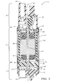
Fig. 2 is an axial cross-sectional view of the fuel pump in accordance with the present invention; -
Fig. 3 is an exploded isometric view of a portion of the fuel pump in accordance with the present invention; -
Fig. 4 is an isometric view of a motor frame of the fuel pump in accordance with the present invention; and -
Fig. 5 is an isometric view of the motor frame ofFig. 4 now shown in a different orientation. - Reference will be made to
Figs. 1 and2 which are an exploded isometric view and an axial cross-sectional view respectively of a fluid pump illustrated asfuel pump 10 for pumping liquid fuel, for example gasoline or diesel fuel, from a fuel tank (not shown) to an internal combustion engine (not shown). While the fluid pump is illustrated asfuel pump 10, it should be understood that the invention is not to be limited to a fuel pump, but could also be applied to fluid pumps for pumping fluids other than fuel.Fuel pump 10 generally includes apump section 12 at one end, amotor section 14 adjacent topump section 12, and anoutlet section 16 adjacent tomotor section 14 at the end offuel pump 10opposite pump section 12. Ahousing 18 offuel pump 10 retainspump section 12,motor section 14 andoutlet section 16 together. Fuel entersfuel pump 10 atpump section 12, a portion of which is rotated bymotor section 14 as will be described in more detail later, and is pumped pastmotor section 14 tooutlet section 16 where the fuel exitsfuel pump 10. -
Motor section 14 includes anelectric motor 20 which is disposed withinhousing 18.Electric motor 20 includes ashaft 22 extending therefrom intopump section 12.Shaft 22 rotates about anaxis 24 when an electric current is applied toelectric motor 20.Electric motor 20 will be described in greater detail later. - With continued reference to
Figs. 1 and2 ,pump section 12 includes aninlet plate 26, animpeller 28, and anoutlet plate 30.Inlet plate 26 is disposed at the end ofpump section 12 that is distal frommotor section 14 whileoutlet plate 30 is disposed at the end ofpump section 12 that is proximal tomotor section 14. Bothinlet plate 26 andoutlet plate 30 are fixed relative tohousing 18 to prevent relative movement betweeninlet plate 26 andoutlet plate 30 with respect tohousing 18.Outlet plate 30 defines aspacer ring 32 on the side ofoutlet plate 30 that faces towardinlet plate 26.Impeller 28 is disposed axially betweeninlet plate 26 andoutlet plate 30 such thatimpeller 28 is radially surrounded byspacer ring 32.Impeller 28 is fixed toshaft 22 such thatimpeller 28 rotates withshaft 22 in a one-to-one relationship.Spacer ring 32 is dimensioned to be slightly thicker than the dimension ofimpeller 28 in the direction ofaxis 24, i.e. the dimension ofspacer ring 32 in the direction ofaxis 24 is greater than the dimension ofimpeller 28 in the direction ofaxis 24. In this way,inlet plate 26,outlet plate 30, andspacer ring 32 are fixed withinhousing 18, for example by crimping the end ofhousing 18 proximal tooutlet plate 30. Axial forces created by the crimping process will be carried byspacer ring 32, thereby preventingimpeller 28 from being clamped tightly betweeninlet plate 26 andoutlet plate 30 which would preventimpeller 28 from rotating freely.Spacer ring 32 is also dimensioned to have an inside diameter that is larger than the outside diameter ofimpeller 28 to allowimpeller 28 to rotate freely withinspacer ring 32 and axially betweeninlet plate 26 andoutlet plate 30. Whilespacer ring 32 is illustrated as being made as a single piece withoutlet plate 30, it should be understood thatspacer ring 32 may alternatively be made as a separate piece that is captured axially betweenoutlet plate 30 andinlet plate 26. -
Inlet plate 26 is generally cylindrical in shape, and includes aninlet 34 that extends throughinlet plate 26 in the same direction asaxis 24. Inlet 34 is a passage which introduces fuel intofuel pump 10.Inlet plate 26 also includes an inletplate flow channel 36 formed in the face ofinlet plate 26 that faces towardimpeller 28. Inletplate flow channel 36 is in fluid communication withinlet 34. -
Outlet plate 30 is generally cylindrical in shape and includes an outletplate outlet passage 40 that extends throughoutlet plate 30 in the same direction asaxis 24. Outletplate outlet passage 40 is in fluid communication withoutlet section 16 as will be describe in more detail later.Outlet plate 30 also includes an outletplate flow channel 42 formed in the face ofoutlet plate 30 that faces towardimpeller 28. Outletplate flow channel 42 is in fluid communication with outletplate outlet passage 40.Outlet plate 30 also includes an outlet plate aperture, hereinafter referred to aslower bushing 44, extending throughoutlet plate 30.Shaft 22 extends throughlower bushing 44 in a close fitting relationship such thatshaft 22 is able to rotate freely withinlower bushing 44 such that radial movement ofshaft 22 withinlower bushing 44 is substantially prevented. In this way,lower bushing 44 radially supports alower end 46 ofshaft 22 that is proximal to pumpsection 12. -
Impeller 28 includes a plurality ofblades 48 arranged in a polar array radially surrounding and centered aboutaxis 24 such thatblades 48 are aligned with inletplate flow channel 36 and outletplate flow channel 42.Blades 48 are each separated from each other by ablade chamber 49 that passes throughimpeller 28 in the general direction ofaxis 24.Impeller 28 may be made, for example only, by a plastic injection molding process in which the preceding features ofimpeller 28 are integrally molded as a single piece of plastic. -
Outlet section 16 includes anend cap 50 having anoutlet 52 for discharging fuel fromfuel pump 10.Outlet 52 may be connected to, for example only, a conduit (not shown) for supplying fuel to an internal combustion engine (not shown).Outlet 52 is in fluid communication with outletplate outlet passage 40 ofoutlet plate 30 for receiving fuel that has been pumped bypump section 12. - With continued reference to
Figs. 1 and2 and with additional reference toFigs. 3 and4 ,electric motor 20 includes a rotor orarmature 54 with a plurality of circumferentially spacedmotor windings 56 and acommutator portion 58, amotor frame 60, a pair ofpermanent magnets 62, and aflux carrier 64. Eachmagnet 62 is in the shape of a segment of a hollow cylinder.Motor frame 60 includes atop section 66 that is proximal tooutlet section 16, a plurality of circumferentially spacedlegs 68 extending axially fromtop section 66 towardpump section 12, and abase section 70 axially spaced apart fromtop section 66 bylegs 68.Top section 66,legs 68, andbase section 70 are preferably integrally formed from a single piece of plastic, for example only, by a plastic injection molding process. -
Top section 66 ofmotor frame 60 includes a firstelectrical terminal 72 and a secondelectrical terminal 74 extending therefrom and protruding throughend cap 50. Firstelectrical terminal 72 and secondelectrical terminal 74 are arranged to be connected to a power source (not shown) such that firstelectrical terminal 72 and secondelectrical terminal 74 are opposite in polarity. Firstelectrical terminal 72 and secondelectrical terminal 74 may be disposed within pre-formed openings intop section 66 or firstelectrical terminal 72 and secondelectrical terminal 74 may be insert molded withtop section 66 whenmotor frame 60 is formed by a plastic injection molding process. Firstelectrical terminal 72 is in electrical communication with afirst carbon brush 76 while secondelectrical terminal 74 is in electrical communication with asecond carbon brush 78.First carbon brush 76 is disposed within afirst brush holder 80 that is defined bytop section 66 and is urged into contact withcommutator portion 58 ofarmature 54 by afirst brush spring 82 that is grounded to endcap 50.Second carbon brush 78 is disposed within asecond brush holder 84 defined bytop section 66 and is urged into contact withcommutator portion 58 ofarmature 54 by asecond brush spring 86 that is grounded to endcap 50.First carbon brush 76 andsecond carbon brush 78 deliver electrical power tomotor windings 56 viacommutator portion 58, thereby rotatingarmature 54 andshaft 22 aboutaxis 24. -
Top section 66 ofmotor frame 60 defines anupper bushing 88 therein which radially supports anupper end 90 ofshaft 22 that is proximal tooutlet section 16.Shaft 22 is able to rotate freely withinupper bushing 88 such that radial movement ofshaft 22 withinupper bushing 88 is substantially prevented. -
Legs 68 are preferably equally circumferentially spaced aroundtop section 66 andbase section 70 and definemotor frame openings 92 betweenlegs 68.Motor frame openings 92 extend axially fromtop section 66 tobase section 70. Onemagnet 62 is disposed within eachmotor frame opening 92.Magnets 62 may be inserted within respectivemotor frame openings 92 aftermotor frame 60 has been formed. Alternatively,magnets 62 may be insert molted withmotor frame 60 whenmotor frame 60 is formed by a plastic injection molding process. In this way,magnets 62 andlegs 68radially surround armature 54. While twolegs 68 and twomagnets 62 have been illustrated, it should be understood that other quantities oflegs 68 andmagnets 62 may be used. -
Base section 70 may be annular in shape and connectslegs 68 to each other.Base section 70 includes abase section recess 94 extending axially thereinto from the end ofbase section 70 that faces away fromtop section 66.Base section recess 94 is coaxial withupper bushing 88 and receivesoutlet plate 30 closely therein such that radial movement ofoutlet plate 30 withinbase section recess 94 is substantially prevented. Sincebase section recess 94 is coaxial withupper bushing 88, a coaxial relationship is maintained betweenlower bushing 44 andupper bushing 88 bybase section 70.Base section 70 also defines anannular shoulder 96 that faces towardtop section 66.Annular shoulder 96 may be substantially perpendicular toaxis 24. -
Flux carrier 64 is made of a ferromagnetic material and may take the form of a cylindrical tube.Flux carrier 64 closely radially surroundslegs 68 ofmotor frame 60 andmagnets 62.Flux carrier 64 may be made, for example only, from a sheet of ferromagnetic material formed to shape by a rolling process. The end offlux carrier 64 that is proximal tobase section 70 ofmotor frame 60 axially abuts annular should 96 ofbase section 70 while the end offlux carrier 64 that is proximal totop section 66 ofmotor frame 60 axially abuts a portion ofend cap 50 that radially surroundstop section 66 ofmotor frame 60. In this way,flux carrier 64 is captured axially betweenend cap 50 andannular shoulder 96 ofbase section 70. - Since
motor frame 60 may be made as a single piece, for example only, by a plastic injection molding process,upper bushing 88 andbase section recess 94 can be made by a single piece of tooling, thereby allowing a high degree of control over the relative positions ofupper bushing 88 andbase section recess 94. Consequently,lower bushing 44 can more easily be maintained in a coaxial relationship withupper bushing 88. Similarly, sincefirst brush holder 80 andsecond brush holder 84 may be defined bytop section 66, for example only, by an injection molding process,first brush holder 80,second brush holder 84, andupper bushing 88 may be formed by a single piece of tooling, thereby allowing a high degree of control over the relative positions offirst brush holder 80,second brush holder 84, andupper bushing 88. Consequently,first brush holder 80 andsecond brush holder 84 can be easily maintained parallel toaxis 24 which may be important forfirst carbon brush 76 andsecond carbon brush 78 to adequately interface withcommutator portion 58 ofarmature 54. - In operation,
inlet 34 is exposed to a volume of fuel (not shown) which is to be pumped to, for example only, an internal combustion engine (not shown). An electric current is supplied tomotor windings 56 in order to rotateshaft 22 andimpeller 28. Asimpeller 28 rotates, fuel is drawn throughinlet 34 into inletplate flow channel 36.Blade chambers 49 allow fuel from inletplate flow channel 36 to flow to outletplate flow channel 42.Impeller 28 subsequently discharges the fuel through outletplate outlet passage 40 and consequently throughoutlet 52. - While this invention has been described in terms of preferred embodiments thereof, it is not intended to be so limited.
Claims (14)
- A fluid pump (10) comprising:an inlet (34) for introducing fluid into said fluid pump (10);an outlet (52) for discharging fluid from said fluid pump (10);a motor (20) having a shaft (22) that rotates about an axis (24), said shaft (22) having an upper end (90) and a lower end (46);a motor frame (60) having a top section (66), a base section (70), and a plurality of legs (68) axially separating said top section (66) and said base section (70); anda lower bushing (44) for radially supporting said lower end (46) of said shaft (22);wherein said top section (66) defines an upper bushing (88) therein for radially supporting said upper end (90) of said shaft (22); andwherein said base section (70) maintains a coaxial relationship between said lower bushing (44) and said upper bushing (88).
- Fluid pump (10) as in claim 1 further comprising:an impeller (28) having an array of blades (48) radially surrounding said axis (24), said impeller (28) being rotatable by said shaft (22) of said motor (20) wherein rotation of said impeller (28) pumps fluid from said inlet (34) to said outlet (52);an inlet plate (26) adjacent to said impeller (28) and including said inlet (34), said inlet plate (26) includes an inlet plate flow channel (36) aligned with said array of blades (48); andan outlet plate (30) adjacent to said impeller (28) on the side said impeller (28) that is opposite said inlet plate (26), said outlet plate (30) having an outlet passage (40) in fluid communication with said outlet (52) and an outlet plate flow channel (42) aligned with said array of blades (48);wherein said outlet plate (30) defines said lower bushing (44).
- Fluid pump (10) according to anyone of the preceding claims wherein said plurality of legs (68) defines motor frame openings (92) spaced circumferentially therebetween.
- Fluid pump (10) as in claim 3 further comprising a plurality of magnets (62) wherein each one of said plurality of magnets (62) is disposed within a respective one of said motor frame openings (92).
- Fluid pump (10) according to anyone of the preceding claims wherein said base section (70) connects each of said plurality of legs (68).
- Fluid pump (10) according to anyone of the preceding claims wherein said base section (70) includes a recess (94) extending axially thereinto.
- Fluid pump (10) according to anyone of the preceding claims wherein said base section (70) is annular in shape.
- Fluid pump (10) according to anyone of the preceding claims wherein said base section (70) defines a shoulder (96) facing toward said top section (66).
- Fluid pump (10) as in claim 8 further comprising a flux carrier (64) radially surrounding said plurality of legs (68) and axially abutting said shoulder (96).
- Fluid pump (10) according to anyone of claims 8 to 9 wherein said shoulder (96) is annular in shape.
- Fluid pump (10) according to anyone of the preceding claims further comprising an end cap (50) positioned over said top section (66) and defining said outlet (52).
- Fluid pump (10) as in claim 11 wherein said flux carrier (64) is captured axially between said end cap (50) and said shoulder (96) of said base section (70).
- Fluid pump (10) according to anyone of the preceding claims further comprising:an armature (54) having a plurality of circumferentially spaced windings (56) wherein said armature (54) is fixed to said shaft (22); anda pair of brushes (76,78) to deliver electrical power to said windings (56);wherein said pair of brushes (76,78) are supported in respective brush holders (80, 84) defined by said top section (66) of said motor frame (60)..
- Fluid pump (10) according to anyone of the preceding claims wherein said wherein said outlet plate (30) is disposed coaxially within said recess (94).
Applications Claiming Priority (1)
| Application Number | Priority Date | Filing Date | Title |
|---|---|---|---|
| US13/865,597 US20140314591A1 (en) | 2013-04-18 | 2013-04-18 | Fluid pump |
Publications (2)
| Publication Number | Publication Date |
|---|---|
| EP2894766A1 true EP2894766A1 (en) | 2015-07-15 |
| EP2894766B1 EP2894766B1 (en) | 2017-09-13 |
Family
ID=50478783
Family Applications (1)
| Application Number | Title | Priority Date | Filing Date |
|---|---|---|---|
| EP14164761.0A Active EP2894766B1 (en) | 2013-04-18 | 2014-04-15 | Fluid pump |
Country Status (3)
| Country | Link |
|---|---|
| US (1) | US20140314591A1 (en) |
| EP (1) | EP2894766B1 (en) |
| CN (1) | CN104110336B (en) |
Cited By (1)
| Publication number | Priority date | Publication date | Assignee | Title |
|---|---|---|---|---|
| DE102018222564A1 (en) * | 2018-12-20 | 2020-06-25 | Continental Automotive Gmbh | Fuel delivery unit and fuel delivery unit |
Families Citing this family (20)
| Publication number | Priority date | Publication date | Assignee | Title |
|---|---|---|---|---|
| US9470181B2 (en) * | 2013-10-16 | 2016-10-18 | Delphi Technologies, Inc. | Sealed shunt wire for a fluid pump |
| US10247185B2 (en) * | 2015-02-25 | 2019-04-02 | Delphi Technologies Ip Limited | Fluid pump |
| US9968874B2 (en) | 2015-04-06 | 2018-05-15 | Delphi Technologies Ip Limited | Fluid pump with a strainer |
| JP2016214008A (en) * | 2015-05-12 | 2016-12-15 | 株式会社ミツバ | Magnet holder and motor device |
| WO2016205792A1 (en) * | 2015-06-19 | 2016-12-22 | Clarcor Engine Mobile Solutions, Llc | Integrated motor-pump |
| US10184475B2 (en) | 2015-07-20 | 2019-01-22 | Delphi Technologies Ip Limited | Fluid pump with flow impedance member |
| US10056800B2 (en) * | 2015-07-30 | 2018-08-21 | Delphi Technologies Ip Limited | Fluid delivery module |
| US9745931B2 (en) | 2015-12-01 | 2017-08-29 | Delphi Technologies, Inc. | Fuel system with a fuel pump control module and a heat sink |
| US10584701B2 (en) | 2017-03-13 | 2020-03-10 | Delphi Technologies Ip Limited | Fluid pump with rotating pumping element wear reduction |
| US10495039B2 (en) | 2017-03-30 | 2019-12-03 | Delphi Technologies Ip Limited | Fuel system having a jet pump |
| US10876541B2 (en) | 2018-03-27 | 2020-12-29 | Delphi Technologies Ip Limited | Fluid pump |
| US10711793B2 (en) * | 2018-03-27 | 2020-07-14 | Delphi Technologies Ip Limited | Fluid pump |
| US10830251B2 (en) | 2018-05-17 | 2020-11-10 | Delphi Technologies Ip Limited | Fluid pump |
| US20190360439A1 (en) | 2018-05-22 | 2019-11-28 | Delphi Technologies Ip Limited | Fuel system with a pressure pulsation damper |
| US20200003166A1 (en) | 2018-07-02 | 2020-01-02 | Delphi Technologies Ip Limited | Fuel system having a jet pump |
| US10662911B1 (en) | 2019-02-15 | 2020-05-26 | Delphi Technologies Ip Limited | Fuel transfer system including a fuel jet pump device and utilized in a partitioned fuel tank |
| US11817758B2 (en) * | 2020-09-18 | 2023-11-14 | Delphi Technologies Ip Limited | Fluid pump and brush spring retainer thereof |
| US11434931B2 (en) | 2020-09-23 | 2022-09-06 | Delphi Technologies Ip Limited | Fuel system having a valve upstream of a jet pump |
| US11441523B1 (en) | 2021-04-16 | 2022-09-13 | Delphi Technologies Ip Limited | Fuel pump driven by an electric motor |
| US11725616B1 (en) * | 2022-03-15 | 2023-08-15 | Delphi Technologies Ip Limited | Sealing ring gland and fuel pump including the same |
Citations (4)
| Publication number | Priority date | Publication date | Assignee | Title |
|---|---|---|---|---|
| JPS63272994A (en) * | 1987-04-30 | 1988-11-10 | Nippon Denso Co Ltd | Motor type fuel pump |
| FR2726702A1 (en) * | 1994-11-07 | 1996-05-10 | Valeo Systemes Dessuyage | Plastic framed electric motor esp. for motor vehicle heating, ventilating and air-conditioning system |
| US20100047090A1 (en) | 2006-10-27 | 2010-02-25 | Patrice Marx | Fuel delivery module |
| EP2327870A2 (en) * | 2009-11-30 | 2011-06-01 | Delphi Technologies, Inc. | Fuel pump with dual outlet pump |
Family Cites Families (7)
| Publication number | Priority date | Publication date | Assignee | Title |
|---|---|---|---|---|
| GB8606494D0 (en) * | 1986-03-17 | 1986-04-23 | Johnson Electric Ind Mfg | Electric motor |
| US5122039A (en) * | 1990-05-29 | 1992-06-16 | Walbro Corporation | Electric-motor fuel pump |
| US6623237B2 (en) * | 2001-08-21 | 2003-09-23 | Delphi Technologies, Inc. | Wear resistant fuel pump |
| DE10327321A1 (en) * | 2003-06-16 | 2005-01-13 | Siemens Ag | As a G-rotor pump trained positive displacement pump |
| US7847457B2 (en) * | 2007-05-09 | 2010-12-07 | Federal-Mogul World Wide, Inc | BLDC motor assembly |
| US7874816B2 (en) * | 2007-09-28 | 2011-01-25 | Delphi Technologies, Inc. | Fuel pump end cap with isolated shunt wires |
| CN102207050B (en) * | 2011-01-18 | 2013-06-05 | 周铁 | Novel brushless motor fuel pump |
-
2013
- 2013-04-18 US US13/865,597 patent/US20140314591A1/en not_active Abandoned
-
2014
- 2014-02-19 CN CN201410056640.4A patent/CN104110336B/en active Active
- 2014-04-15 EP EP14164761.0A patent/EP2894766B1/en active Active
Patent Citations (4)
| Publication number | Priority date | Publication date | Assignee | Title |
|---|---|---|---|---|
| JPS63272994A (en) * | 1987-04-30 | 1988-11-10 | Nippon Denso Co Ltd | Motor type fuel pump |
| FR2726702A1 (en) * | 1994-11-07 | 1996-05-10 | Valeo Systemes Dessuyage | Plastic framed electric motor esp. for motor vehicle heating, ventilating and air-conditioning system |
| US20100047090A1 (en) | 2006-10-27 | 2010-02-25 | Patrice Marx | Fuel delivery module |
| EP2327870A2 (en) * | 2009-11-30 | 2011-06-01 | Delphi Technologies, Inc. | Fuel pump with dual outlet pump |
Cited By (3)
| Publication number | Priority date | Publication date | Assignee | Title |
|---|---|---|---|---|
| DE102018222564A1 (en) * | 2018-12-20 | 2020-06-25 | Continental Automotive Gmbh | Fuel delivery unit and fuel delivery unit |
| DE102018222564B4 (en) | 2018-12-20 | 2022-07-21 | Vitesco Technologies GmbH | Fuel delivery unit and fuel delivery unit |
| US11802528B2 (en) | 2018-12-20 | 2023-10-31 | Vitesco Technologies GmbH | Fuel delivery assembly and fuel delivery unit |
Also Published As
| Publication number | Publication date |
|---|---|
| US20140314591A1 (en) | 2014-10-23 |
| EP2894766B1 (en) | 2017-09-13 |
| CN104110336B (en) | 2018-03-06 |
| CN104110336A (en) | 2014-10-22 |
Similar Documents
| Publication | Publication Date | Title |
|---|---|---|
| EP2894766B1 (en) | Fluid pump | |
| US10557479B2 (en) | Fluid pump with flow impedance member | |
| US8257064B2 (en) | Electric fuel pump capable of supplying fuel at high flow rate | |
| US10544763B2 (en) | Fuel pump and fuel supply system using the same | |
| US7874817B2 (en) | Fuel pump assembly with a vapor purge passage arrangement for a fuel pump module | |
| EP2863520B1 (en) | Fluid pump and a manufacturing method for a fluid pump. | |
| US10830251B2 (en) | Fluid pump | |
| US10056800B2 (en) | Fluid delivery module | |
| US6939115B2 (en) | Wet-type rotor pump | |
| US10711793B2 (en) | Fluid pump | |
| SE449124B (en) | ELECTRICALLY DRIVEN FUEL PUMP FOR USE IN THE FUEL INJECTION SYSTEM FOR A SPARK TURN COMBUSTION ENGINE | |
| US10876541B2 (en) | Fluid pump | |
| US10148150B2 (en) | Liquid pump | |
| US20170023022A1 (en) | Fluid pump | |
| US20070210673A1 (en) | Fuel pump having bearing member | |
| KR101815931B1 (en) | Brushless Direct Current Motor of Fuel Pump for Motor Vehicle | |
| US11817758B2 (en) | Fluid pump and brush spring retainer thereof | |
| CN100552209C (en) | Fluid pump with housing | |
| US20130323024A1 (en) | Fuel pump | |
| US20230136175A1 (en) | Pump and motor vehicle having at least one such pump | |
| US20070065315A1 (en) | Fluid pump having bearing hold | |
| CN115217698A (en) | fuel pump driven by electric motor | |
| JP6131797B2 (en) | Fuel pump | |
| JPWO2015104818A1 (en) | Fuel pump module | |
| WO2018186865A1 (en) | Vane pump assembly with integral motor |
Legal Events
| Date | Code | Title | Description |
|---|---|---|---|
| PUAI | Public reference made under article 153(3) epc to a published international application that has entered the european phase |
Free format text: ORIGINAL CODE: 0009012 |
|
| 17P | Request for examination filed |
Effective date: 20140415 |
|
| AK | Designated contracting states |
Kind code of ref document: A1 Designated state(s): AL AT BE BG CH CY CZ DE DK EE ES FI FR GB GR HR HU IE IS IT LI LT LU LV MC MK MT NL NO PL PT RO RS SE SI SK SM TR |
|
| AX | Request for extension of the european patent |
Extension state: BA ME |
|
| R17P | Request for examination filed (corrected) |
Effective date: 20160115 |
|
| RBV | Designated contracting states (corrected) |
Designated state(s): AL AT BE BG CH CY CZ DE DK EE ES FI FR GB GR HR HU IE IS IT LI LT LU LV MC MK MT NL NO PL PT RO RS SE SI SK SM TR |
|
| GRAP | Despatch of communication of intention to grant a patent |
Free format text: ORIGINAL CODE: EPIDOSNIGR1 |
|
| RIC1 | Information provided on ipc code assigned before grant |
Ipc: F04D 29/046 20060101ALI20170308BHEP Ipc: H02K 23/04 20060101ALI20170308BHEP Ipc: F04D 13/06 20060101ALI20170308BHEP Ipc: H02K 1/17 20060101AFI20170308BHEP Ipc: H02K 5/167 20060101ALI20170308BHEP Ipc: F04D 29/62 20060101ALI20170308BHEP Ipc: H02K 5/15 20060101ALI20170308BHEP Ipc: F04D 5/00 20060101ALI20170308BHEP Ipc: H02K 5/14 20060101ALN20170308BHEP |
|
| INTG | Intention to grant announced |
Effective date: 20170412 |
|
| RIN1 | Information on inventor provided before grant (corrected) |
Inventor name: HERRERA, DANIEL Inventor name: ASLAM, MOHAMMED Inventor name: FISCHER, JOHN G. Inventor name: GONZALES, GUSTAVO |
|
| GRAS | Grant fee paid |
Free format text: ORIGINAL CODE: EPIDOSNIGR3 |
|
| GRAA | (expected) grant |
Free format text: ORIGINAL CODE: 0009210 |
|
| AK | Designated contracting states |
Kind code of ref document: B1 Designated state(s): AL AT BE BG CH CY CZ DE DK EE ES FI FR GB GR HR HU IE IS IT LI LT LU LV MC MK MT NL NO PL PT RO RS SE SI SK SM TR |
|
| REG | Reference to a national code |
Ref country code: GB Ref legal event code: FG4D |
|
| REG | Reference to a national code |
Ref country code: CH Ref legal event code: EP |
|
| REG | Reference to a national code |
Ref country code: IE Ref legal event code: FG4D |
|
| REG | Reference to a national code |
Ref country code: AT Ref legal event code: REF Ref document number: 929032 Country of ref document: AT Kind code of ref document: T Effective date: 20171015 |
|
| REG | Reference to a national code |
Ref country code: DE Ref legal event code: R096 Ref document number: 602014014446 Country of ref document: DE |
|
| REG | Reference to a national code |
Ref country code: NL Ref legal event code: MP Effective date: 20170913 |
|
| REG | Reference to a national code |
Ref country code: LT Ref legal event code: MG4D |
|
| PG25 | Lapsed in a contracting state [announced via postgrant information from national office to epo] |
Ref country code: NO Free format text: LAPSE BECAUSE OF FAILURE TO SUBMIT A TRANSLATION OF THE DESCRIPTION OR TO PAY THE FEE WITHIN THE PRESCRIBED TIME-LIMIT Effective date: 20171213 Ref country code: FI Free format text: LAPSE BECAUSE OF FAILURE TO SUBMIT A TRANSLATION OF THE DESCRIPTION OR TO PAY THE FEE WITHIN THE PRESCRIBED TIME-LIMIT Effective date: 20170913 Ref country code: HR Free format text: LAPSE BECAUSE OF FAILURE TO SUBMIT A TRANSLATION OF THE DESCRIPTION OR TO PAY THE FEE WITHIN THE PRESCRIBED TIME-LIMIT Effective date: 20170913 Ref country code: SE Free format text: LAPSE BECAUSE OF FAILURE TO SUBMIT A TRANSLATION OF THE DESCRIPTION OR TO PAY THE FEE WITHIN THE PRESCRIBED TIME-LIMIT Effective date: 20170913 Ref country code: LT Free format text: LAPSE BECAUSE OF FAILURE TO SUBMIT A TRANSLATION OF THE DESCRIPTION OR TO PAY THE FEE WITHIN THE PRESCRIBED TIME-LIMIT Effective date: 20170913 |
|
| REG | Reference to a national code |
Ref country code: AT Ref legal event code: MK05 Ref document number: 929032 Country of ref document: AT Kind code of ref document: T Effective date: 20170913 |
|
| PG25 | Lapsed in a contracting state [announced via postgrant information from national office to epo] |
Ref country code: LV Free format text: LAPSE BECAUSE OF FAILURE TO SUBMIT A TRANSLATION OF THE DESCRIPTION OR TO PAY THE FEE WITHIN THE PRESCRIBED TIME-LIMIT Effective date: 20170913 Ref country code: RS Free format text: LAPSE BECAUSE OF FAILURE TO SUBMIT A TRANSLATION OF THE DESCRIPTION OR TO PAY THE FEE WITHIN THE PRESCRIBED TIME-LIMIT Effective date: 20170913 Ref country code: ES Free format text: LAPSE BECAUSE OF FAILURE TO SUBMIT A TRANSLATION OF THE DESCRIPTION OR TO PAY THE FEE WITHIN THE PRESCRIBED TIME-LIMIT Effective date: 20170913 Ref country code: GR Free format text: LAPSE BECAUSE OF FAILURE TO SUBMIT A TRANSLATION OF THE DESCRIPTION OR TO PAY THE FEE WITHIN THE PRESCRIBED TIME-LIMIT Effective date: 20171214 Ref country code: BG Free format text: LAPSE BECAUSE OF FAILURE TO SUBMIT A TRANSLATION OF THE DESCRIPTION OR TO PAY THE FEE WITHIN THE PRESCRIBED TIME-LIMIT Effective date: 20171213 |
|
| PG25 | Lapsed in a contracting state [announced via postgrant information from national office to epo] |
Ref country code: NL Free format text: LAPSE BECAUSE OF FAILURE TO SUBMIT A TRANSLATION OF THE DESCRIPTION OR TO PAY THE FEE WITHIN THE PRESCRIBED TIME-LIMIT Effective date: 20170913 |
|
| REG | Reference to a national code |
Ref country code: FR Ref legal event code: PLFP Year of fee payment: 5 |
|
| PG25 | Lapsed in a contracting state [announced via postgrant information from national office to epo] |
Ref country code: CZ Free format text: LAPSE BECAUSE OF FAILURE TO SUBMIT A TRANSLATION OF THE DESCRIPTION OR TO PAY THE FEE WITHIN THE PRESCRIBED TIME-LIMIT Effective date: 20170913 Ref country code: RO Free format text: LAPSE BECAUSE OF FAILURE TO SUBMIT A TRANSLATION OF THE DESCRIPTION OR TO PAY THE FEE WITHIN THE PRESCRIBED TIME-LIMIT Effective date: 20170913 Ref country code: PL Free format text: LAPSE BECAUSE OF FAILURE TO SUBMIT A TRANSLATION OF THE DESCRIPTION OR TO PAY THE FEE WITHIN THE PRESCRIBED TIME-LIMIT Effective date: 20170913 |
|
| PG25 | Lapsed in a contracting state [announced via postgrant information from national office to epo] |
Ref country code: AT Free format text: LAPSE BECAUSE OF FAILURE TO SUBMIT A TRANSLATION OF THE DESCRIPTION OR TO PAY THE FEE WITHIN THE PRESCRIBED TIME-LIMIT Effective date: 20170913 Ref country code: IT Free format text: LAPSE BECAUSE OF FAILURE TO SUBMIT A TRANSLATION OF THE DESCRIPTION OR TO PAY THE FEE WITHIN THE PRESCRIBED TIME-LIMIT Effective date: 20170913 Ref country code: SM Free format text: LAPSE BECAUSE OF FAILURE TO SUBMIT A TRANSLATION OF THE DESCRIPTION OR TO PAY THE FEE WITHIN THE PRESCRIBED TIME-LIMIT Effective date: 20170913 Ref country code: SK Free format text: LAPSE BECAUSE OF FAILURE TO SUBMIT A TRANSLATION OF THE DESCRIPTION OR TO PAY THE FEE WITHIN THE PRESCRIBED TIME-LIMIT Effective date: 20170913 Ref country code: EE Free format text: LAPSE BECAUSE OF FAILURE TO SUBMIT A TRANSLATION OF THE DESCRIPTION OR TO PAY THE FEE WITHIN THE PRESCRIBED TIME-LIMIT Effective date: 20170913 Ref country code: IS Free format text: LAPSE BECAUSE OF FAILURE TO SUBMIT A TRANSLATION OF THE DESCRIPTION OR TO PAY THE FEE WITHIN THE PRESCRIBED TIME-LIMIT Effective date: 20180113 |
|
| REG | Reference to a national code |
Ref country code: DE Ref legal event code: R097 Ref document number: 602014014446 Country of ref document: DE |
|
| PLBE | No opposition filed within time limit |
Free format text: ORIGINAL CODE: 0009261 |
|
| STAA | Information on the status of an ep patent application or granted ep patent |
Free format text: STATUS: NO OPPOSITION FILED WITHIN TIME LIMIT |
|
| PG25 | Lapsed in a contracting state [announced via postgrant information from national office to epo] |
Ref country code: DK Free format text: LAPSE BECAUSE OF FAILURE TO SUBMIT A TRANSLATION OF THE DESCRIPTION OR TO PAY THE FEE WITHIN THE PRESCRIBED TIME-LIMIT Effective date: 20170913 |
|
| 26N | No opposition filed |
Effective date: 20180614 |
|
| PG25 | Lapsed in a contracting state [announced via postgrant information from national office to epo] |
Ref country code: MC Free format text: LAPSE BECAUSE OF FAILURE TO SUBMIT A TRANSLATION OF THE DESCRIPTION OR TO PAY THE FEE WITHIN THE PRESCRIBED TIME-LIMIT Effective date: 20170913 Ref country code: SI Free format text: LAPSE BECAUSE OF FAILURE TO SUBMIT A TRANSLATION OF THE DESCRIPTION OR TO PAY THE FEE WITHIN THE PRESCRIBED TIME-LIMIT Effective date: 20170913 |
|
| REG | Reference to a national code |
Ref country code: CH Ref legal event code: PL |
|
| REG | Reference to a national code |
Ref country code: BE Ref legal event code: MM Effective date: 20180430 |
|
| GBPC | Gb: european patent ceased through non-payment of renewal fee |
Effective date: 20180415 |
|
| REG | Reference to a national code |
Ref country code: IE Ref legal event code: MM4A |
|
| PG25 | Lapsed in a contracting state [announced via postgrant information from national office to epo] |
Ref country code: LU Free format text: LAPSE BECAUSE OF NON-PAYMENT OF DUE FEES Effective date: 20180415 |
|
| REG | Reference to a national code |
Ref country code: DE Ref legal event code: R081 Ref document number: 602014014446 Country of ref document: DE Owner name: DELPHI TECHNOLOGIES IP LIMITED, BB Free format text: FORMER OWNER: DELPHI TECHNOLOGIES, INC., TROY, MICH., US |
|
| PG25 | Lapsed in a contracting state [announced via postgrant information from national office to epo] |
Ref country code: GB Free format text: LAPSE BECAUSE OF NON-PAYMENT OF DUE FEES Effective date: 20180415 Ref country code: LI Free format text: LAPSE BECAUSE OF NON-PAYMENT OF DUE FEES Effective date: 20180430 Ref country code: CH Free format text: LAPSE BECAUSE OF NON-PAYMENT OF DUE FEES Effective date: 20180430 Ref country code: BE Free format text: LAPSE BECAUSE OF NON-PAYMENT OF DUE FEES Effective date: 20180430 |
|
| PG25 | Lapsed in a contracting state [announced via postgrant information from national office to epo] |
Ref country code: IE Free format text: LAPSE BECAUSE OF NON-PAYMENT OF DUE FEES Effective date: 20180415 |
|
| PG25 | Lapsed in a contracting state [announced via postgrant information from national office to epo] |
Ref country code: MT Free format text: LAPSE BECAUSE OF NON-PAYMENT OF DUE FEES Effective date: 20180415 |
|
| PG25 | Lapsed in a contracting state [announced via postgrant information from national office to epo] |
Ref country code: TR Free format text: LAPSE BECAUSE OF FAILURE TO SUBMIT A TRANSLATION OF THE DESCRIPTION OR TO PAY THE FEE WITHIN THE PRESCRIBED TIME-LIMIT Effective date: 20170913 |
|
| PG25 | Lapsed in a contracting state [announced via postgrant information from national office to epo] |
Ref country code: PT Free format text: LAPSE BECAUSE OF FAILURE TO SUBMIT A TRANSLATION OF THE DESCRIPTION OR TO PAY THE FEE WITHIN THE PRESCRIBED TIME-LIMIT Effective date: 20170913 |
|
| PG25 | Lapsed in a contracting state [announced via postgrant information from national office to epo] |
Ref country code: HU Free format text: LAPSE BECAUSE OF FAILURE TO SUBMIT A TRANSLATION OF THE DESCRIPTION OR TO PAY THE FEE WITHIN THE PRESCRIBED TIME-LIMIT; INVALID AB INITIO Effective date: 20140415 Ref country code: MK Free format text: LAPSE BECAUSE OF NON-PAYMENT OF DUE FEES Effective date: 20170913 Ref country code: CY Free format text: LAPSE BECAUSE OF FAILURE TO SUBMIT A TRANSLATION OF THE DESCRIPTION OR TO PAY THE FEE WITHIN THE PRESCRIBED TIME-LIMIT Effective date: 20170913 |
|
| PG25 | Lapsed in a contracting state [announced via postgrant information from national office to epo] |
Ref country code: AL Free format text: LAPSE BECAUSE OF FAILURE TO SUBMIT A TRANSLATION OF THE DESCRIPTION OR TO PAY THE FEE WITHIN THE PRESCRIBED TIME-LIMIT Effective date: 20170913 |
|
| P01 | Opt-out of the competence of the unified patent court (upc) registered |
Effective date: 20230327 |
|
| REG | Reference to a national code |
Ref country code: DE Ref legal event code: R081 Ref document number: 602014014446 Country of ref document: DE Owner name: PHINIA DELPHI LUXEMBOURG SARL, LU Free format text: FORMER OWNER: DELPHI TECHNOLOGIES IP LIMITED, ST. MICHAEL, BB |
|
| PGFP | Annual fee paid to national office [announced via postgrant information from national office to epo] |
Ref country code: DE Payment date: 20250317 Year of fee payment: 12 |
|
| PGFP | Annual fee paid to national office [announced via postgrant information from national office to epo] |
Ref country code: FR Payment date: 20260317 Year of fee payment: 13 |