EP2894729A1 - Connector and electronic device provided with same - Google Patents
Connector and electronic device provided with same Download PDFInfo
- Publication number
- EP2894729A1 EP2894729A1 EP13834454.4A EP13834454A EP2894729A1 EP 2894729 A1 EP2894729 A1 EP 2894729A1 EP 13834454 A EP13834454 A EP 13834454A EP 2894729 A1 EP2894729 A1 EP 2894729A1
- Authority
- EP
- European Patent Office
- Prior art keywords
- contact
- hole
- contact portion
- stop
- connector
- Prior art date
- Legal status (The legal status is an assumption and is not a legal conclusion. Google has not performed a legal analysis and makes no representation as to the accuracy of the status listed.)
- Withdrawn
Links
- 230000005489 elastic deformation Effects 0.000 claims abstract description 13
- 238000009413 insulation Methods 0.000 claims abstract description 8
- 229920005989 resin Polymers 0.000 claims description 12
- 239000011347 resin Substances 0.000 claims description 12
- 239000004033 plastic Substances 0.000 abstract description 3
- 238000006073 displacement reaction Methods 0.000 description 13
- 230000013011 mating Effects 0.000 description 6
- 239000002184 metal Substances 0.000 description 6
- 238000004078 waterproofing Methods 0.000 description 4
- 230000000903 blocking effect Effects 0.000 description 3
- 238000000034 method Methods 0.000 description 3
- 239000000470 constituent Substances 0.000 description 2
- 238000003780 insertion Methods 0.000 description 2
- 230000037431 insertion Effects 0.000 description 2
- 238000005476 soldering Methods 0.000 description 2
- 239000004677 Nylon Substances 0.000 description 1
- 239000003822 epoxy resin Substances 0.000 description 1
- 238000004519 manufacturing process Methods 0.000 description 1
- 239000000463 material Substances 0.000 description 1
- 238000012986 modification Methods 0.000 description 1
- 230000004048 modification Effects 0.000 description 1
- 238000000465 moulding Methods 0.000 description 1
- 229920001778 nylon Polymers 0.000 description 1
- 230000003287 optical effect Effects 0.000 description 1
- 229920000647 polyepoxide Polymers 0.000 description 1
Images




Classifications
-
- H—ELECTRICITY
- H01—ELECTRIC ELEMENTS
- H01R—ELECTRICALLY-CONDUCTIVE CONNECTIONS; STRUCTURAL ASSOCIATIONS OF A PLURALITY OF MUTUALLY-INSULATED ELECTRICAL CONNECTING ELEMENTS; COUPLING DEVICES; CURRENT COLLECTORS
- H01R13/00—Details of coupling devices of the kinds covered by groups H01R12/70 or H01R24/00 - H01R33/00
- H01R13/46—Bases; Cases
- H01R13/52—Dustproof, splashproof, drip-proof, waterproof, or flameproof cases
- H01R13/5216—Dustproof, splashproof, drip-proof, waterproof, or flameproof cases characterised by the sealing material, e.g. gels or resins
-
- H—ELECTRICITY
- H01—ELECTRIC ELEMENTS
- H01R—ELECTRICALLY-CONDUCTIVE CONNECTIONS; STRUCTURAL ASSOCIATIONS OF A PLURALITY OF MUTUALLY-INSULATED ELECTRICAL CONNECTING ELEMENTS; COUPLING DEVICES; CURRENT COLLECTORS
- H01R24/00—Two-part coupling devices, or either of their cooperating parts, characterised by their overall structure
- H01R24/58—Contacts spaced along longitudinal axis of engagement
-
- H—ELECTRICITY
- H01—ELECTRIC ELEMENTS
- H01R—ELECTRICALLY-CONDUCTIVE CONNECTIONS; STRUCTURAL ASSOCIATIONS OF A PLURALITY OF MUTUALLY-INSULATED ELECTRICAL CONNECTING ELEMENTS; COUPLING DEVICES; CURRENT COLLECTORS
- H01R24/00—Two-part coupling devices, or either of their cooperating parts, characterised by their overall structure
- H01R24/38—Two-part coupling devices, or either of their cooperating parts, characterised by their overall structure having concentrically or coaxially arranged contacts
-
- H—ELECTRICITY
- H01—ELECTRIC ELEMENTS
- H01R—ELECTRICALLY-CONDUCTIVE CONNECTIONS; STRUCTURAL ASSOCIATIONS OF A PLURALITY OF MUTUALLY-INSULATED ELECTRICAL CONNECTING ELEMENTS; COUPLING DEVICES; CURRENT COLLECTORS
- H01R13/00—Details of coupling devices of the kinds covered by groups H01R12/70 or H01R24/00 - H01R33/00
- H01R13/02—Contact members
- H01R13/10—Sockets for co-operation with pins or blades
- H01R13/11—Resilient sockets
- H01R13/111—Resilient sockets co-operating with pins having a circular transverse section
-
- H—ELECTRICITY
- H01—ELECTRIC ELEMENTS
- H01R—ELECTRICALLY-CONDUCTIVE CONNECTIONS; STRUCTURAL ASSOCIATIONS OF A PLURALITY OF MUTUALLY-INSULATED ELECTRICAL CONNECTING ELEMENTS; COUPLING DEVICES; CURRENT COLLECTORS
- H01R13/00—Details of coupling devices of the kinds covered by groups H01R12/70 or H01R24/00 - H01R33/00
- H01R13/46—Bases; Cases
- H01R13/52—Dustproof, splashproof, drip-proof, waterproof, or flameproof cases
- H01R13/5202—Sealing means between parts of housing or between housing part and a wall, e.g. sealing rings
-
- H—ELECTRICITY
- H01—ELECTRIC ELEMENTS
- H01R—ELECTRICALLY-CONDUCTIVE CONNECTIONS; STRUCTURAL ASSOCIATIONS OF A PLURALITY OF MUTUALLY-INSULATED ELECTRICAL CONNECTING ELEMENTS; COUPLING DEVICES; CURRENT COLLECTORS
- H01R2107/00—Four or more poles
Definitions
- the invention relates to connectors and electronic devices with the connectors.
- a conventional jack connector is described in Patent Literature 1.
- the connector includes a body and a plurality of contacts.
- the body has a connection hole adapted to receive a plug (mating connector).
- the contacts are arranged, in spaced relation to each other, on either side in a first direction in the connection hole of the body.
- the contacts each include an elastically deformable contact portion.
- Patent Literature 1 Japanese published utility model application No. 49-135788 .
- the pressed contact portions may be displaced beyond a predetermined displacement range and thereby plastically deformed.
- An object of the invention is to provide a connector capable of suppressing plastic deformation of contact portions of contacts and to provide an electronic device provided with the connector.
- a connector of the invention includes a first contact, a second contact, and a first stop having an insulation property.
- the second contact is disposed in spaced relation to the first contact along a first direction.
- the first contact includes a contact portion, the contact portion being elastically deformable toward the second contact.
- the first stop is disposed between the first and second contacts and on an elastic deformation direction side of the contact portion so as to be abuttable on the contact portion.
- the contact portion of the first contact elastically deforms, the contact portion abuts on the first stop and therefore will not be displaced beyond a predetermined displacement range. Therefore, it is possible to inhibit the contact portion of the first contact from being displaced beyond the predetermined displacement range and thereby plastically deformed even when the mating connector is pried so as to press the contact portion.
- the first stop is interposed between the first and second contacts. This arrangement can reduce the possibility of upsizing the connector because of the inclusion of the first stop. Further, the first stop, having an insulation property, can prevent electrical connection between the first and second contacts via the interposed first stop.
- the first stop may include a base and an abuttable portion.
- the base may be interposed between the first and second contacts.
- the abuttable portion may be contiguous with the base and disposed on the elastic deformation direction side of the contact portion so as to be abuttable on the contact portion.
- the abuttable portion may have a dimension in the first direction that differs from that of the base.
- the connector of this aspect makes it possible to define a displacement range of the contact portion of the first contact simply by differentiating the dimension in the first direction of the abuttable portion different from that of the base.
- the connector may further include the body.
- the body may hold the first and second contacts in spaced relation to each other along the first direction.
- the connector may further include a cover.
- the body may have a connection hole extending in a second direction through the body.
- the second direction may be orthogonal to the first direction.
- the first stop may be contiguous with the cover and extend to a first side of the second direction.
- the cover may block a portion on a second side of the second direction of the connection hole.
- the cover blocking the portion on the second side of the second direction of the connection hole can improve waterproofing and dustproofing properties of the connector.
- the first stop is contiguous with the cover, it is possible to interpose the first stop between the first and second contacts when blocking the portion on the second side of the second direction of the connection hole with the cover. It is thus possible to mount the first stop with ease.
- the connector may further include a cover.
- the first stop may be contiguous with the cover and extend to a first side of a second direction.
- the second direction may be orthogonal to the first direction.
- the body may have a connection hole, and a first fitting hole on a second side of the second direction relative to the connection hole.
- the first fitting hole may communicate with the connection hole.
- the cover may fittingly engage with the first fitting hole and may block a portion on the second side of the second direction of the connection hole.
- the cover fittingly engages with the first fitting hole and blocks the portion on the second side of the second direction of the connection hole.
- This arrangement can improve waterproofing and dustproofing properties of the connector.
- the first stop is contiguous with the cover, it is possible to interpose the first stop between the first and second contacts when blocking the portion on the second side of the second direction of the connection hole with the cover. It is thus possible to mount the first stop with ease.
- the first contact may further include a fixed portion.
- the fixed portion may have a hole.
- the contact portion may be contiguous with an edge of the hole of the fixed portion.
- the contact portion may be elastically deformable toward the second contact so as to be received into the hole and abuttable on the first stop.
- the contact portion when the contact portion elastically deforms toward the second contact, the contact portion is received in the hole of the fixed portion and abuts on the first stop.
- This arrangement can reduce the lengthwise dimension of the first stop contiguous with the cover. This further reduces the possibility of upsizing the connector because of the inclusion of the first stop.
- the connector may further include a seal.
- the body may further have a second fitting hole on the second side of the second direction relative to the first fitting hole.
- the second fitting hole may communicate with the first fitting hole.
- the seal may be a resin being filled in the second fitting hole and overlying the cover.
- the seal being a resin being filled in the second fitting hole and overlying the cover, can improve waterproofing and dustproofing properties of the connector.
- the cover may include a projection projecting to the second side of the second direction.
- the projection may be embedded in the seal.
- the projection of the cover, embedded in the seal can improve the degree of adhesion of the cover to the seal.
- the connector may further include a third contact, a forth contact, a fifth contact, a sixth contact, and a second stop having an insulation property.
- the second, third, fourth, fifth, and sixth contacts may each include a contact portion.
- the fourth, fifth, and sixth contacts may be arranged, in spaced relation to each other along the first direction, at positions in the body that are on a first side of the first direction relative to the connection hole, and the contact portions of the fourth, fifth, and sixth contacts may be arranged in the connection hole, in spaced relation to each other along the second direction.
- the first, second, and third contacts may be arranged, in spaced relation to each other along the first direction, at positions in the body that are on a second side of the first direction relative to the connection hole, and the contact portions of the first, second, and third contacts may be arranged inside the connection hole, in spaced relation to each other along the second direction.
- the contact portion of the fourth contact may be elastically deformable toward the fifth contact.
- the second stop may be disposed between the fourth contact and the fifth contact and on an elastic deformation direction side of the contact portion of the fourth contact so as to be abuttable on the contact portion of the fourth contact.
- the contact portion of the fourth contact when the contact portion of the fourth contact elastically deforms, the contact portion of the fourth contact abuts on the second stop. This prevents the contact portion of the fourth contact from being displaced beyond a predetermined amount. This can inhibit the contact portion of the fourth contact from being displaced beyond the predetermined displacement range and thereby plastically deformed even when the mating connector is pried so as to press the contact portion.
- the second stop is interposed between the fourth and fifth contacts. This arrangement can reduce the possibility of upsizing the connector because of the inclusion of the second stop. Further, the second stop, having an insulation property, can prevent electrical connection between the fourth and fifth contacts via the interposed second stop.
- the electronic device of the invention is provided with the connector of any of the above aspects.
- the connector C illustrated in Figs. 1A and 1B is a multi-contact jack connector, which is connectable with a plug P (a mating connector, see Figs. 6A and 6B ).
- the connector C includes a body 100, a first contact 200a, a second contact 200b, a third contact 200c, a fourth contact 200d, a fifth contact 200e, a sixth contact 200f, a first stop 300a, a second stop 300b, a cover 400, and a seal 500.
- FIGS. 2A and 2B show a first direction X, which is the widthwise direction of the connector C.
- Figs. 2A , 3A , and 3B show a second direction Y, which is the lengthwise direction of the connector C.
- Figs. 2A , 3A , and 3B show a third direction Z, which is the heightwise direction of the connector C.
- the second direction Y is orthogonal to the first direction X.
- the third direction Z is orthogonal to the first direction X and the second direction Y.
- the first contact 200a is a plate metal formed by stamping.
- the first contact 200a includes a fixed portion 210a, a contact portion 220a, and a tail 230a.
- the fixed portion 210a is a plate extending in the second direction Y, including first and second ends in the second direction Y (front and rear ends) and a rectangular hole 211 a.
- the hole 211 a has first and second edges in the second direction Y.
- the contact portion 220a is a plate contiguous with the first edge of the hole 211 a and extends to a second side of the second direction (extends rearwards) with an inclination to a first side of the first direction X.
- the contact portion 220a is elastically deformable to a second side of the first direction X (i.e., toward the second contact).
- the contact portion 220a as elastically deforming can enter into the hole 211 a.
- the distal portion of the contact portion 220a is curved in a circular arc shape bowed to the first side of the first direction X.
- the tail 230a is a generally L-shaped plate contiguous with a lower part of the second end of the fixed portion 210a.
- the second contact 200b is a plate metal formed by stamping.
- the second contact 200b includes a fixed portion 210b, a contact portion 220b, and a tail 230b.
- the fixed portion 210b is a plate extending in the second direction Y and including first and second ends in the second direction Y (front and rear ends).
- the contact portion 220b is a plate contiguous with the first end of the fixed portion 210b and extends to a first side of the second direction Y (extends frontwards) with an inclination to the first side of the first direction X.
- the contact portion 220b is elastically deformable to the second side of the first direction X.
- the distal portion of the contact portion 220b is curved in a circular arc shape bowed to the first side of the first direction X.
- the tail 230b is a generally L-shaped plate contiguous with a lower part of the second end of the fixed portion 210b.
- the third contact 200c is a plate metal formed by stamping.
- the third contact 200c includes a fixed portion 210c, a contact portion 220c, and a tail 230c.
- the fixed portion 210c is a plate extending in the second direction Y and including first and second ends in the second direction Y (front and rear ends).
- the fixed portion 210c is larger in dimension in the second direction Y than the fixed portion 210b is.
- the contact portion 220c is a plate contiguous with the first end of the fixed portion 210c, extending to the first side in the second direction Y (extends frontwards) with an inclination to the first side of the first direction X.
- the contact portion 220c is larger in dimension in the second direction Y than the contact portion 220b is.
- the contact portion 220c is elastically deformable to the second side of the first direction X.
- the distal portion of the contact portion 220c is curved in a circular arc shape bowed to the first side of the first direction X.
- the tail 230c is a generally L-shaped plate contiguous with a lower part of the second end of the fixed portion 210c.
- the fourth contact 200d is a plate metal formed by stamping.
- the fourth contact 200d differs from the first contact 200a in being a mirror image of the first contact 200a and having no tail portion. Except for these, the fourth contact 200d has substantially the same shape as the first contact 200a.
- the fourth contact 200d includes a fixed portion 210d and a contact portion 220d.
- the contact portion 220d is elastically deformable to the first side of the first direction (i.e., toward the fifth contact).
- the contact portion 220d as elastically deforming can enter into a hole 211 d.
- the fifth contact 200e is a plate metal formed by stamping.
- the fifth contact 200e has substantially the same shape as the second contact 200b except for the following two differences.
- the first difference is that the fifth contact 200e is a mirror image of the second contact 200b.
- the second difference is that the fixed portion 210e and the contact portion 220e are respectively larger in dimension in the second direction Y than the fixed portion 210b and the contact portion 220b are.
- the fifth contact 200e includes a tail 230e.
- the sixth contact 200f is a plate metal formed by stamping.
- the sixth contact 200f has substantially the same shape as the third contact 200c except for the following two differences.
- the first difference is that the sixth contact 200f is a mirror image of the third contact 200c.
- the second difference is that the fixed portion 210f and the contact portion 220f are respectively larger in dimension in the second direction Y than the fixed portion 210c and the contact portion 220c are.
- the sixth contact 200f includes a tail 230f.
- the body 100 is made of an insulating resin. As illustrated in Figs. 2A to 3B , the body 100 includes a main body 110, a projected part 120, a connection hole 130, first and second fitting holes 141 and 142, housing grooves 151, 152, 153, 154, 155, and 156, housing holes 161, 162, 163, and 164, and a holding part 170.
- the main body 110 is a rectangular parallelepiped block having a front face (first end face in the second direction Y) and a rear face (second end face in the second direction Y).
- the projected part 120 is an elliptic cylinder projecting from the front face of the main body 110.
- connection hole 130 and the first and second fitting holes 141 and 142 extend in the second direction Y through the main body 110 and the projected part 120.
- the connection hole 130 extends in the second direction Y inside the main body 110 and the projected part 120, opening in the front face of the projected part 120 to the first side of the second direction Y.
- the connection hole 130 can receive the plug P.
- the holding part 170 is provided centrally in an area on the second side of the second direction Y of the connection hole 130.
- the holding part 170 is a plate extending between inner faces on the first and second sides of the third direction Z of the connection hole 130.
- the holding part 170 has a generally circular holding hole 171.
- the holding hole 171 can fittingly receive the distal portion of the plug P.
- the first fitting hole 141 is a rectangular hole in the main body 110, more particularly at a portion thereof on the second side of the second direction Y relative to the connection hole 130.
- the first fitting hole 141 communicates with the connection hole 130 and has larger outer dimensions than the connection hole 130.
- the second fitting hole 142 is a rectangular hole in the main body 110, more particularly at a portion thereof on the second side of the second direction Y relative to the first fitting hole 141.
- the second fitting hole 142 communicates with the first fitting hole 141 and has larger outer dimensions than the first fitting hole 141.
- the second fitting hole 142 opens in the rear face of the main body 110 to the second side of the second direction Y.
- the housing grooves 151, 152, and 153 are provided in spaced relation to each other along the first direction X in the body 100, at positions on the second side of the first direction X relative to the connection hole 130.
- the housing hole 161 is provided in the body 100, at a position on the first side of the second direction Y (on the front side) relative to the housing grooves 151 and 152.
- the housing hole 162 is provided in the body 100, at a position on the first side of the second direction Y (on the front side) relative to the housing groove 153.
- the housing grooves 154, 155, and 156 are provided in spaced relation to each other along the first direction X in the body 100, at positions on the first side of the first direction X relative to the connection hole 130.
- the housing hole 163 is provided in the body 100, at a position on the first side of the second direction Y (front side) relative to the housing grooves 153 and 154.
- the housing hole 164 is provided in the body 100, at a position on the first side of the second direction Y (front side) relative to the housing groove 156. Specific arrangements will be described below.
- the housing groove 151 is provided in the body 100, at a position on the second side of the first direction X relative to the connection hole 130.
- the housing groove 151 extends in the second direction Y and communicates with the connection hole 130.
- the housing groove 151 is slightly larger in dimension in the second direction Y than the fixed portion 210a of the first contact 200a.
- the housing groove 151 is slightly smaller in dimension in the third direction Z than the fixed portion 210a of the first contact 200a.
- the fixed portion 210a is press-fitted and held in the housing groove 151.
- the contact portion 220a of the first contact 200a is disposed in the connection hole 130.
- the housing groove 152 is provided in the body 100, at a position on the second side of the first direction X relative to the housing groove 151 with a space therebetween.
- the housing groove 152 extends in the second direction Y and communicates with the housing groove 151.
- the housing groove 152 is slightly larger in dimension in the second direction Y than the fixed portion 210b of the second contact 200b.
- the housing groove 152 is slightly smaller in dimension in the third direction Z than the fixed portion 210b of the second contact 200b.
- the fixed portion 210b is press-fitted and held in the housing groove 152.
- the housing hole 161 is provided in the body 100, at a position on the first side of the second direction Y (front side) relative to the housing grooves 151 and 152.
- the housing hole 161 is a horizontal hole extending in the second direction Y and communicating with the housing grooves 151 and 152 and the connection hole 130.
- the contact portion 220b of the second contact 200b is received in the housing hole 161.
- the distal portion of the contact portion 220b is disposed in the connection hole 130.
- the distal portion of the contact portion 220b is located on the first side of the second direction Y relative to the distal portion of the contact portion 220a of the first contact 200a.
- the housing groove 153 is provided in the body 100, at a position on the second side of the first direction X relative to the housing groove 152 with a space therebetween.
- the housing groove 153 extends in the second direction Y and communicates with the housing groove 152.
- the housing groove 153 is slightly larger in dimension in the second direction Y than the fixed portion 210c of the third contact 200c.
- the housing groove 153 is slightly smaller in dimension in the third direction Z than the fixed portion 210c of the third contact 200c.
- the fixed portion 210c is press-fitted and held in the housing groove 153.
- the housing hole 162 is provided in the body 100, at a position on the first side of the second direction Y (on the front side) relative to the housing groove 153.
- the housing hole 162 is a horizontal hole extending in the second direction Y and communicating with the housing groove 153 and the housing hole 161.
- the contact portion 220c of the third contact 200c is received in the housing holes 161 and 162.
- the distal portion of the contact portion 220c is disposed in the connection hole 130.
- the distal portion of the contact portion 220c is located on the first side of the second direction Y relative to the distal portion of the contact portion 220b of the second contact 200b.
- the housing groove 154 is provided in the body 100, at a position on the first side of the first direction X relative to the connection hole 130.
- the housing groove 154 extends in the second direction Y and communicates with the connection hole 130.
- the housing groove 154 is slightly larger in dimension in the second direction Y than the fixed portion 210d of the fourth contact 200d.
- the housing groove 154 is slightly smaller in dimension in the third direction Z than the fixed portion 210d of the fourth contact 200d.
- the fixed portion 210d is press-fitted and held in the housing groove 154.
- the contact portion 220d of the fourth contact 200d is disposed in the connection hole 130 and faces the contact portion 220a of the first contact 200a.
- the housing groove 155 is provided in the body 100, at a position on the first side of the first direction X relative to the housing groove 154 with a space therebetween.
- the housing groove 155 extends in the second direction Y and communicates with the housing groove 154.
- the housing groove 155 is slightly larger in dimension in the second direction Y than the fixed portion 210e of the fifth contact 200e.
- the housing groove 155 is slightly smaller in dimension in the third direction Z than the fixed portion 210e of the fifth contact 200e.
- the fixed portion 210e is press-fitted and held in the housing groove 155.
- the housing hole 163 is provided in the body 100, at a position on the first side of the second direction Y (on the front side) relative to the housing grooves 154 and 155.
- the housing hole 163 is a horizontal hole extending in the second direction Y and communicating with the housing grooves 154 and 155 and the connection hole 130.
- the contact portion 220e of the fifth contact 200e is received in the housing hole 163.
- the distal portion of the contact portion 220e is received in the connection hole 130.
- the distal portion of the contact portion 220e is disposed on the first side of the second direction Y relative to the distal portion of the contact portion 220d of the fourth contact 200d and faces the distal portion of the contact portion 220c of the third contact 200c.
- the housing groove 156 is provided in the body 100, at a position on the first side of the first direction X relative to the housing groove 155 with a space therebetween.
- the housing groove 156 extends in the second direction Y and communicates with the housing groove 155.
- the housing groove 155 is slightly larger in dimension in the second direction Y than the fixed portion 210f of the sixth contact 200f.
- the housing groove 156 is slightly smaller in dimension in the third direction Z than the fixed portion 210f of the sixth contact 200f.
- the fixed portion 210f is press-fitted and held in the housing groove 156.
- the housing hole 164 is provided in the body 100, at a position on the first side of the second direction Y (on the front side) relative to the housing groove 156.
- the housing hole 164 is a horizontal hole extending in the second direction Y and communicates with the housing groove 156 and the housing hole 163.
- the contact portion 220f of the sixth contact 200f is received in the housing holes 163 and 164.
- the distal portion of the contact portion 220f is disposed in the connection hole 130 and located on the first side of the second direction Y relative to the distal portion of the contact portion 220e of the fifth contact 200e.
- the cover 400, the first stop 300a, and the second stop 300b are integrally formed of an insulating resin.
- the cover 400 includes a cover body 410 and a pair of projections 420.
- the cover body 410 is a rectangular plate.
- the outer shape of the cover body 410 conforms to the inner shape of the first fitting hole 141 of the body 100.
- the cover body 410 fittingly engages with the first fitting hole 141 so as to block a portion on the second side of the second direction Y of the connection hole 130.
- Slits 411, 412, and 413 are provided, in spaced relation to each other along the first direction X, toward the second end in the first direction X of the lower portion of the cover body 410.
- the slits 411, 412, and 413 have dimensions in the first direction X that are substantially equal to those of the respective tails 230a, 230b, 230c of the first, second, and third contacts 200a, 200b, 200c.
- the slits 411, 412, and 413 have dimensions in the third direction Z that are substantially equal to those of the respective tails 230a, 230b, 230c.
- the slits 411, 412, and 413 have dimensions in the second direction Y that are smaller than those of the respective tails 230a, 230b, 230c.
- the tails 230a, 230b, and 230c partially fit in the slits 411, 412, 413, respectively, and project therefrom to the second side of the second direction Y.
- Slits 414 and 415 are provided, in spaced relation to each other along the first direction X, toward the first end in the first direction X of the lower portion of the cover body 410.
- the slits 414 and 415 have dimensions in the first direction X that are substantially equal to those of the respective tails 230e, 230f of the fifth and sixth contacts 200e, 200f.
- the slits 414 and 415 have dimensions in the third direction Z that are substantially equal to those of the respective tails 230e and 230f.
- the slits 414 and 415 have dimensions in the second direction Y that are smaller than those of the respective tails 230e, 230f.
- the tails 230e and 230f partially fit in the slits 414 and 415, respectively, and project therefrom to the second side of the second direction Y.
- a pair of recesses 416 is provided, in spaced relation to each other along the first direction X, in a central portion of a first end face in the second direction Y (inner face) of the cover body 410.
- the first end face of the cover body 410 is provided with the first and second stops 300a, 300b.
- the first and second stops 300a, 300b extend to the first side of the second direction Y.
- the first stop 300a includes a base 310a and an abuttable portion 320a
- the second stop 300b includes a base 310b and an abuttable portion 320b.
- the base 310a is integrally connected to the cover body 410 and interposed between the fixed portions 210a, 210b of the first and second contacts 200a, 200b. In other words, the base 310a is in contact with the fixed portions 210a, 210b of the first and second contacts 200a, 200b.
- the abuttable portion 320a extends from the base 310a to the first side of the second direction Y and is located on the elastic deformation direction side of the contact portion 220a of the first contact 200a so as to be abuttable on the distal portion of the contact portion 220a. Specifically, the abuttable portion 320a faces the distal portion of the contact portion 220a through the hole 211 a of the fixed portion 210a.
- the abuttable portion 320a is of different dimension in the first direction X from that of the base 310a. In the present embodiment, the abuttable portion 320a is smaller in dimension in the first direction X than the base 310a. This defines a displacement range of the distal portion of the contact portion 220a (a range between the initial position as shown in Fig. 2A and an abutment position in which the distal portion of the contact portion 220a abuts the abuttable portion 320d).
- the base 310b is integrally connected to the cover body 410 and interposed between the fixed portions 210d, 210e of the fourth and fifth contacts 200d, 200e. In other words, the base 310b is in contact with the fixed portions 210d, 210e of the fourth and fifth contacts 200d, 200e.
- the abuttable portion 320b extends from the base 310b to the first side of the second direction Y and is located on the elastic deformation direction side of the contact portion 220d of the fourth contact 200d so as to be abuttable on the distal portion of the contact portion 220d. Specifically, the abuttable portion 320b faces the distal portion of the contact portion 220d through the hole 211d of the fixed portion 210d.
- the abuttable portion 320b is of different dimension in the first direction X from that of the base 310b. In the present embodiment, the abuttable portion 320b is smaller in dimension in the first direction X than the base 310b. This defines a displacement range of the distal portion of the contact portion 220d (a range between an initial position as shown in Fig. 2A and an abutment position in which the distal portion of the contact portion 220d abuts the abuttable portion 320d).
- the pair of projections 420 of trapezoidal shape are arranged, in spaced relation to each other along the first direction X, on the second end face in the second direction Y (outer face) of the cover body 410.
- the seal 500 is a resin (e.g., an epoxy resin or nylon-based insulating resin) which is filled in the second fitting hole 142 of the body 100 to overlie the cover 400.
- the projections 420 of the cover 400 are partially embedded in the central portion of the seal 500.
- the tails 230a, 230b, 230c, 230e, and 230f are partially embedded in a second end portion in the third direction Z (lower portion) of the seal 500. In other words, the tails 230a, 230b, 230c, 230e, and 230f pass through the seal 500 (see Fig. 2A ).
- the body 100 and the first to sixth contacts 200a to 200f are prepared.
- the contact portion 220c of the third contact 200c is then inserted through the housing groove 153 of the body 100 into the housing holes 162 and 161, and the fixed portion 210c of the third contact 200c is pressed into the housing groove 153.
- the distal portion of the contact portion 220c is inserted through the housing holes 162 and 161 into the connection hole 130.
- the contact portion 220b of the second contact 200b is inserted through the housing groove 152 of the body 100 into the housing hole 161, and the fixed portion 210b of the second contact 200b is pressed into the housing groove 152.
- the distal portion of the contact portion 220b is inserted through the housing hole 161 into the connection hole 130. Then, the fixed portion 210a of the first contact 200a is pressed into the housing groove 151 of the body 100. Accordingly, the contact portion 220a of the first contact 200a is inserted through the housing groove 151 into the connection hole 130 of the body 100.
- the fixed portions 210a, 210b, 210c of the first, second, and third contacts 200a, 200b, 200c are held, in spaced relation to each other, at the positions in the body 100 which are on the second side of the first direction X relative to the connection hole 130, while the contact portions 220a, 220b, 220c of the first, second, and third contacts 200a, 200b, 200c are arranged in the connection hole 130, in spaced relation to each other along the second direction Y.
- the contact portion 220f of the sixth contact 200f is inserted through the housing groove 156 of the body 100 into the housing holes 164, 163, and the fixed portion 210f of the sixth contact 200f is pressed into the housing groove 156.
- the distal portion of the contact portion 220f is inserted through the housing holes 164, and 163 into the connection hole 130.
- the contact portion 220e of the fifth contact 200e is inserted through the housing groove 155 of the body 100 into the housing hole 163, and the fixed portion 210e of the fifth contact 200e is pressed into the housing groove 155.
- the distal portion of the contact portion 220e is inserted through the housing hole 163 into the connection hole 130.
- the fixed portion 210d of the fourth contact 200d is pressed into the housing groove 154 of the body 100. Accordingly, the contact portion 220d of the fourth contact 200d is inserted through the housing groove 154 into the connection hole 130 of the body 100.
- the fixed portions 210d, 210e, 210f of the fourth, fifth, and sixth contacts 200d, 200e, 200f are held, in spaced relation to each other, at the positions in the body 100 that are on the first side of the first direction X relative to the connection hole 130, while the contact portions 220d, 220e, 220f of the fourth, fifth, and sixth contacts 200d, 200e, 200f are arranged in the connection hole 130, in spaced relation to each other along the second direction Y,.
- the first stop 300a is then pushed into the space between the fixed portions 210a, 210b of the first and second contacts 200a, 200b.
- the base 310a of the first stop 300a is thus interposed between the fixed portions 210a, 210b, while the abuttable portion 320a is located on the elastic deformation direction side of the contact portion 220a of the first contact 200a so as to be abuttable on the contact portion 220a.
- the second stop 300b is also pushed into the space between the fixed portions 210d, 210e of the fourth and fifth contacts 200d, 200e.
- the base 310b of the second stop 300b is thus interposed between the fixed portions 210d, 210e, while the abuttable portion 320b is located on the elastic deformation direction side of the contact portion 220d of the fourth contact 200d so as to be abuttable on the contact portion 220d.
- the cover 400 is fitted to the first fitting hole 141 of the body 100.
- the tails 230a, 230b, 230c of the first, second, and third contacts 200a, 200b, 200c partially fit in the respective slits 411, 412, and 413 of the cover 400 and project therefrom to the second side of the second direction Y.
- the tails 230e, 230f of the fifth and sixth contacts 200e, 200f partially fit in the respective slits 414 and 415 and project therefrom to the second side of the second direction Y.
- the body 100, the first to sixth contacts 200a to 200f, the cover 400, and the first and second stops 300a and 300b are arranged inside a mold (not shown).
- an insulating resin is filled into the second fitting hole 142 of the body 100.
- the insulating resin forms the seal 500 to overlie the cover body 410 of the cover 400.
- the projections 420 of the cover 400 are partially embedded in the insulating resin, and the tails 230a, 230b, 230c, 230e, and 230f are partially embedded in the insulating resin. Accordingly, the tails 230a, 230b, 230c, 230e, and 230f pass through the seal 500 in the second direction Y.
- the following describes in detail a procedure to mount the connector C assembled as described above on a circuit board of an electronic device (not shown).
- the connector C is placed on the circuit board.
- the tails 230a, 230b, 230c, 230e of the first, second, third, and fifth contacts 200a, 200b, 200c, 200e are respectively brought into contact with electrodes of the circuit board.
- the tail 230f of the sixth contact 200f is brought into contact with an earth electrode of the circuit board.
- the tails 230a, 230b, 230c, 230e of the first, second, third, and fifth contacts 200a, 200b, 200c, 200e are respectively connected by soldering to the electrodes of the circuit board.
- the tail 230f of the sixth contact 200f is connected by soldering to the earth electrodes of the circuit board.
- the connector C is thus mounted on the electronic device.
- the following describes a procedure to connect a plug P to the connector C.
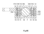
- the plug P is inserted into the connection hole 130 of the body 100 of the connector C as illustrated in Figs. 6A and 6B .
- the distal portion of the plug P thus fits in the holding hole 171 of the holding part 170 of the connector C.
- a first electrode (not shown) of the plug P is inserted into a space between the distal portion of the contact portion 220a of the first contact 200a and the distal portion of the contact portion 220d of the fourth contact 200d.
- the contact portion 220a of the first contact 200a pressed by the first electrode of the plug P, elastically deforms to the second side of the first direction X (toward the second contact 200b).
- the distal portion of the contact portion 220a is accordingly displaced to the second side of the first direction X (toward the second contact 200b).
- the distal portion of the contact portion 220a does not abut on the abuttable portion 320a of the first stop 300a.
- the contact portion 220d of the fourth contact 200d pressed by the first electrode of the plug P, elastically deforms to the first side of the first direction X (toward the fifth contact 200e).
- the distal portion of the contact portion 220d is accordingly displaced to the first side of the first direction X (toward the fifth contact 200e).
- the distal portion of the contact portion 220d does not abut on the abuttable portion 320b of the second stop 300b.
- a second electrode (not shown) of the plug P makes elastic contact with the distal portion of the contact portion 220b of the second contact 200b.
- the contact portion 220b of the second contact 200b pressed by the second electrode of the plug P, elastically deforms to the second side of the first direction X.
- the distal portion of the contact portion 220b is accordingly displaced to the second side of the first direction X.
- a third electrode (not shown) of the plug P is inserted into a space between the distal portion of the contact portion 220c of the third contact 200c and the distal portion of the contact portion 220e of the fifth contact 200e.
- the contact portion 220c of the third contact 200c pressed by the third electrode of the plug P, elastically deforms to the second side of the first direction X.
- the distal portion of the contact portion 220c is accordingly displaced to the second side of the first direction X.
- the contact portion 220e of the fifth contact 200e pressed by the third electrode of the plug P, elastically deforms to the first side of the first direction X.
- the distal portion of the contact portion 220e is accordingly displaced to the first side of the first direction X.
- the earth electrode (not shown) of the plug P makes elastic contact with the distal portion of the contact portion 320f of the sixth contact 300f.
- the contact portion 220f of the sixth contact 200f pressed by the earth electrode of the plug P, elastically deforms to the first side of the first direction X.
- the distal portion of the contact portion 220f is accordingly displaced to the first side of the first direction X.
- the plug P may be pried to the first side of the first direction X.
- the distal portion of the plug P moves to the second side of the first direction X.
- the first electrode of the plug P accordingly presses the contact portion 220a of the first contact 200a to the second side of the first direction X, so that the contact portion 220a elastically deforms to the second side of the first direction X (toward the second contact 200b).
- the distal portion of the contact portion 220a is accordingly displaced to the second side of the first direction X (toward the second contact 200b), inserted into the hole 211 a of the fixed portion 210a, and brought into abutment with the abuttable portion 320a of the first stop 300a. This suppresses displacement beyond the predetermined displacement range of the distal portion of the contact portion 220a.
- the plug P may be pried to the second side of the first direction X.
- the distal portion of the plug P moves to the first side of the first direction X.
- the first electrode of the plug P accordingly presses the contact portion 220d of the fourth contact 200d to the first side of the first direction X, so that the contact portion 220d elastically deforms to the first side of the first direction X (toward the fifth contact 200e).
- the distal portion of the contact portion 220d is accordingly displaced to the first side of the first direction X (toward the fifth contact 200e), inserted into the hole 211d of the fixed portion 210d, and brought into abutment with the abuttable portion 320b of the second stop 300b. This suppresses displacement beyond the predetermined displacement range of the distal portion of the contact portion 220d.
- the connector C has the following technical features. First, it is possible to suppress plastic deformation of the contact portions 220a and 220d. This is because the contact portions 220a and 220d of the first and fourth contacts 200a, 200d are prevented from undergoing displacement beyond the predetermined displacement ranges by respectively abutting on the first and second stops 300a, 300b. Second, the connector C is hardly upsized although it is provided with the first and second stops 200a and 200b. This is because the first stop 300a is interposed between the first and second contacts 200a, 200b and the second stop 300b is interposed between the fourth and fifth contacts 200d, 200e.
- first and second stops 300a, 300b contiguous with the cover 400 are arranged to respectively face the contact portions 220a, 220d through the respective holes 211 a, 211d of the fixed portions 210a, 220d. It is therefore possible to suppress increase in dimension in the second direction Y (length dimension) of the first and second stops 300a, 300b although they are abuttable on the contact portions 220a, 220d, respectively. It is accordingly possible to suppress upsizing of the connector C.
- first and second contacts 200a, 200b are made of an insulating resin.
- the first and second stops 200a, 200b are made of an insulating resin.
- the first and second stops 300a, 300b are integral with the cover 400. In conjunction with a step of fitting the cover 400 in the first fitting hole 141 of the body 100, it is possible to insert the first stop 300a into the space between the first and second contacts 200a, 200b and the second stop 300b into the space between the fourth and fifth contacts 200d, 200e.
- the connector C has improved waterproofing and dustproofing properties. This is because the cover 400 fittingly engages with the first fitting hole 141 of the body 100 and the seal 500 is filled in the second fitting hole 142.
- the cover 400 has improved degree of adhesion to the seal 500 for the following reason.
- the cover 400 has increased contact areas with the seal 500 because the projections 420 of the cover 400 are embedded in the seal 500.
- the connector C is not limited to the above embodiment and may be modified in any manner within the scope of claims. The following describes in details such modifications.
- the fourth, fifth, and sixth contacts 200d, 200e, 200f are arranged, in spaced relation to each other, at the positions in the body 100 that are on the first side of the first direction X relative to the connection hole 130.
- the first, second, and third contacts 200a, 200b, 200c are arranged, in spaced relation to each other, at the positions in the body 100 that are on the second side of the first direction X relative to the connection hole 130.
- these arrangements may be modified in any manner as long as the first and second contacts arranged in spaced relation to each other along the first direction. In other words, the third to sixth contacts may be omitted.
- the first contact 200a includes the fixed portion 210a, the contact portion 220a, and the tail 230a.
- the first contact may be modified in any manner as long as it has a contact portion that is elastically deformable toward the second contact.
- the contact portion 220a of the first contact 200a is contiguous with the first edge of the hole 211a of the fixed portion 210a.
- the contact portion of the first contact is not limited thereto.
- the contact portion of the first contact may be contiguous with an end in the second direction of the fixed portion and extends to the first side of the second direction with an inclination to the first side of the first direction.
- the contact portion of the first contact may be contiguous with the second edge of the hole of the fixed portion and extends to the first side of the second direction with an inclination to the first side of the first direction.
- the contact portion of the fourth contact may be modified in a similar manner to that of the first contact.
- the second to sixth contacts may be modified in shape in any manner.
- the first stop 300a is interposed between the first and second contacts 200a, 200b, and the abuttable portion 320a of the first stop 300a is disposed so as to be abuttable on the contact portion 220a of the first contact 200a.
- the first stop may be modified in any manner as long as it has an insulation property, is interposed between the first and second contacts, and is disposed on the elastic deformation direction side of the contact portion of the first contact so as to be abuttable on this contact portion.
- the abuttable portion 320a is smaller in dimension in the first direction X than the base 310a.
- the abuttable portion may be of dimension in the first direction that is equal to that of the base.
- the abuttable portion may be larger in dimension in the first direction than the base.
- the first stop 300a is provided integrally with the cover 400.
- the first stop may be separate from the cover. Such a separate first stop may be held directly between the first and second contacts so as to be securely positioned. Also, the first stop may be connected to a connection hole in the cover.
- the second stop may be omitted.
- the second stop may be modified in a similar manner to the first stop.
- the connector of the invention may be provided with another stop or stops in addition to the first and second stops.
- such a stop or stops may be interposed between the second and third contacts and/or between the fifth and sixth contacts.
- the stop(s) may be disposed on the elastic deformation direction side(s) of the contact portion(s) of the second contact and/or the fifth contact so as to be abuttable on the contact portion(s).
- the cover 400 fittingly engages with the first fitting hole 141 of the body 100, and the seal 500 is filled in the second fitting hole 142 of the body 100.
- the cover and/or the seal may be omitted.
- the cover may be modified in any manner as long as it can fittingly engage with the first fitting hole.
- the body 100 includes the main body 110, the projected part 120, the connection hole 130, the first and second fitting holes 141 and 142, the housing grooves 151, 152, 153, 154, 155 and 156, the housing holes 161, 162, 163 and 164, and the holding part 170.
- the body may be modified in any manner as long as it is adapted to hold the first contact and the second contact in spaced relation to each other along the first direction.
- the first contact and the second contact may be embedded by insert molding in the body, in spaced relation to each other along the first direction.
- the body may be formed with a space to receive the first stop between the first contact and the second contact.
- the first and second contacts and the first stop may be insert-molded in the body.
- the first fitting hole 141 is provided at a portion of the body 100 on the second side of the second direction Y relative to the connection hole 130, and the second fitting hole 142 is provided on the second side of the second direction Y relative to the first fitting hole 141.
- the first fitting hole and/or the second fitting hole may be omitted.
- the cover can fittingly engage with first fitting hole so as block a portion on the second side of the second direction of the connection hole.
- the connection hole may extend through the body in the second direction. In this case, the cover may block a portion on the second side of the second direction of the connection hole.
- the seal may overlie a portion on the second side of the second direction of the body and also overlie the cover. It is possible to omit the cover and/or the seal modified in any of the above manners.
- the cover modified in any of the above manners may be provided separately from the first and second stops as described above.
- the connector C is a jack connector.
- the connector C is applicable to connectors other than jack connectors, such as USB connectors, HDMI (registered trademark) connectors, optical connectors, and connectors for IC cards.
- the connector C is connectable to a plug as a mating connector.
- the mating connector of the invention may be any type of connector that is connectable to the connector of the invention.
- the first direction X is the widthwise direction of the connector C
- the second direction Y is the lengthwise direction of the connector C
- the third direction Z is the heightwise direction of the connector C.
- the first, second, and third directions may be defined in any manner.
- the first direction may be the heightwise direction of the connector
- the second direction may be the lengthwise direction of the connector
- the third direction may be the widthwise direction of the connector.
Landscapes
- Chemical & Material Sciences (AREA)
- Dispersion Chemistry (AREA)
- Connector Housings Or Holding Contact Members (AREA)
- Coupling Device And Connection With Printed Circuit (AREA)
Abstract
Description
- The invention relates to connectors and electronic devices with the connectors.
- A conventional jack connector is described in Patent Literature 1. The connector includes a body and a plurality of contacts. The body has a connection hole adapted to receive a plug (mating connector). The contacts are arranged, in spaced relation to each other, on either side in a first direction in the connection hole of the body. The contacts each include an elastically deformable contact portion.
- Patent Literature 1: Japanese published utility model application No.
49-135788 - In the above connector, when a plug as received in the connection hole of the body is pried in the first direction so as to press the contact portions of the contacts, the pressed contact portions may be displaced beyond a predetermined displacement range and thereby plastically deformed.
- The invention has been conceived in view of the above circumstances. An object of the invention is to provide a connector capable of suppressing plastic deformation of contact portions of contacts and to provide an electronic device provided with the connector.
- To solve the above problem, a connector of the invention includes a first contact, a second contact, and a first stop having an insulation property. The second contact is disposed in spaced relation to the first contact along a first direction. The first contact includes a contact portion, the contact portion being elastically deformable toward the second contact. The first stop is disposed between the first and second contacts and on an elastic deformation direction side of the contact portion so as to be abuttable on the contact portion.
- In the connector of this aspect, when the contact portion of the first contact elastically deforms, the contact portion abuts on the first stop and therefore will not be displaced beyond a predetermined displacement range. Therefore, it is possible to inhibit the contact portion of the first contact from being displaced beyond the predetermined displacement range and thereby plastically deformed even when the mating connector is pried so as to press the contact portion. In addition, the first stop is interposed between the first and second contacts. This arrangement can reduce the possibility of upsizing the connector because of the inclusion of the first stop. Further, the first stop, having an insulation property, can prevent electrical connection between the first and second contacts via the interposed first stop.
- The first stop may include a base and an abuttable portion. The base may be interposed between the first and second contacts. The abuttable portion may be contiguous with the base and disposed on the elastic deformation direction side of the contact portion so as to be abuttable on the contact portion. The abuttable portion may have a dimension in the first direction that differs from that of the base.
- The connector of this aspect makes it possible to define a displacement range of the contact portion of the first contact simply by differentiating the dimension in the first direction of the abuttable portion different from that of the base.
- The connector may further include the body. The body may hold the first and second contacts in spaced relation to each other along the first direction.
- The connector may further include a cover. The body may have a connection hole extending in a second direction through the body. The second direction may be orthogonal to the first direction. The first stop may be contiguous with the cover and extend to a first side of the second direction. The cover may block a portion on a second side of the second direction of the connection hole.
- In the connector of this aspect, the cover blocking the portion on the second side of the second direction of the connection hole can improve waterproofing and dustproofing properties of the connector. In addition, as the first stop is contiguous with the cover, it is possible to interpose the first stop between the first and second contacts when blocking the portion on the second side of the second direction of the connection hole with the cover. It is thus possible to mount the first stop with ease.
- The connector may further include a cover. The first stop may be contiguous with the cover and extend to a first side of a second direction. The second direction may be orthogonal to the first direction. The body may have a connection hole, and a first fitting hole on a second side of the second direction relative to the connection hole. The first fitting hole may communicate with the connection hole. The cover may fittingly engage with the first fitting hole and may block a portion on the second side of the second direction of the connection hole.
- In the connector of this aspect, the cover fittingly engages with the first fitting hole and blocks the portion on the second side of the second direction of the connection hole. This arrangement can improve waterproofing and dustproofing properties of the connector. In addition, as the first stop is contiguous with the cover, it is possible to interpose the first stop between the first and second contacts when blocking the portion on the second side of the second direction of the connection hole with the cover. It is thus possible to mount the first stop with ease.
- The first contact may further include a fixed portion. The fixed portion may have a hole. The contact portion may be contiguous with an edge of the hole of the fixed portion. The contact portion may be elastically deformable toward the second contact so as to be received into the hole and abuttable on the first stop.
- In the connector of this aspect, when the contact portion elastically deforms toward the second contact, the contact portion is received in the hole of the fixed portion and abuts on the first stop. This arrangement can reduce the lengthwise dimension of the first stop contiguous with the cover. This further reduces the possibility of upsizing the connector because of the inclusion of the first stop.
- The connector may further include a seal. The body may further have a second fitting hole on the second side of the second direction relative to the first fitting hole. The second fitting hole may communicate with the first fitting hole. The seal may be a resin being filled in the second fitting hole and overlying the cover.
- In the connector of this aspect, the seal, being a resin being filled in the second fitting hole and overlying the cover, can improve waterproofing and dustproofing properties of the connector.
- The cover may include a projection projecting to the second side of the second direction. The projection may be embedded in the seal.
- In the connector of this aspect, the projection of the cover, embedded in the seal, can improve the degree of adhesion of the cover to the seal.
- The connector may further include a third contact, a forth contact, a fifth contact, a sixth contact, and a second stop having an insulation property. The second, third, fourth, fifth, and sixth contacts may each include a contact portion. The fourth, fifth, and sixth contacts may be arranged, in spaced relation to each other along the first direction, at positions in the body that are on a first side of the first direction relative to the connection hole, and the contact portions of the fourth, fifth, and sixth contacts may be arranged in the connection hole, in spaced relation to each other along the second direction. The first, second, and third contacts may be arranged, in spaced relation to each other along the first direction, at positions in the body that are on a second side of the first direction relative to the connection hole, and the contact portions of the first, second, and third contacts may be arranged inside the connection hole, in spaced relation to each other along the second direction. The contact portion of the fourth contact may be elastically deformable toward the fifth contact. The second stop may be disposed between the fourth contact and the fifth contact and on an elastic deformation direction side of the contact portion of the fourth contact so as to be abuttable on the contact portion of the fourth contact.
- In the connector of this aspect, when the contact portion of the fourth contact elastically deforms, the contact portion of the fourth contact abuts on the second stop. This prevents the contact portion of the fourth contact from being displaced beyond a predetermined amount. This can inhibit the contact portion of the fourth contact from being displaced beyond the predetermined displacement range and thereby plastically deformed even when the mating connector is pried so as to press the contact portion. In addition, the second stop is interposed between the fourth and fifth contacts. This arrangement can reduce the possibility of upsizing the connector because of the inclusion of the second stop. Further, the second stop, having an insulation property, can prevent electrical connection between the fourth and fifth contacts via the interposed second stop.
- The electronic device of the invention is provided with the connector of any of the above aspects.
-
-
Fig. 1A is a perspective view of a connector according to an embodiment of the invention as viewed from the front, top, right side of the connector; -
Fig. 1B is a perspective view of the connector as viewed from the rear, bottom, left side thereof; -
Fig. 2A is a cross-sectional view of the connector taken alongline 2A-2A inFig. 1A ; -
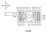
Fig. 2B is a cross-sectional view of the connector taken alongline 2B-2B inFig. 1A ; -
Fig. 3A is a cross-sectional view of the connector taken alongline 3A-3A inFig. 1A ; -
Fig. 3B is a cross-sectional view of the connector taken alongline 3B-3B inFig. 1A ; -
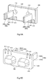
Fig. 4A is a perspective view of a cover and first and second stops of the connector as viewed from the front, top right side thereof; -
Fig. 4B is a perspective view of the cover and the first and second stops of the connector as viewed from the rear, bottom, right side thereof; -
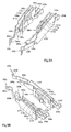
Fig. 5A is a perspective view of first to sixth contacts of the connector as viewed from the front, top, right side thereof; -
Fig. 5B is a perspective view of the first to sixth contacts of the connector as viewed from the rear, bottom, left side thereof; -
Fig. 6A is a cross-sectional view of the connector taken alongline 2A-2A inFig. 1A , with a plug inserted in the connector; and -
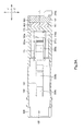
Fig. 6B is a cross-sectional view of the connector taken alongline 2B-2B inFig. 1A , with the plug inserted in the connector. - A connector C according to an embodiment of the invention will be described below with reference to
Figs. 1A to 6B . The connector C illustrated inFigs. 1A and1B is a multi-contact jack connector, which is connectable with a plug P (a mating connector, seeFigs. 6A and6B ). As illustrated inFigs. 2A to 3B , the connector C includes abody 100, afirst contact 200a, asecond contact 200b, athird contact 200c, afourth contact 200d, afifth contact 200e, asixth contact 200f, afirst stop 300a, asecond stop 300b, acover 400, and aseal 500. These constituents of the connector C will be described below in detail.Figs. 2A and2B show a first direction X, which is the widthwise direction of the connector C.Figs. 2A ,3A , and3B show a second direction Y, which is the lengthwise direction of the connector C.Figs. 2A ,3A , and3B show a third direction Z, which is the heightwise direction of the connector C. The second direction Y is orthogonal to the first direction X. The third direction Z is orthogonal to the first direction X and the second direction Y. - As illustrated in
Figs. 2A ,2B ,5A, and 5B , thefirst contact 200a is a plate metal formed by stamping. Thefirst contact 200a includes a fixedportion 210a, acontact portion 220a, and atail 230a. - As illustrated in
Figs. 2A ,5A, and 5B , the fixedportion 210a is a plate extending in the second direction Y, including first and second ends in the second direction Y (front and rear ends) and arectangular hole 211 a. Thehole 211 a has first and second edges in the second direction Y. Thecontact portion 220a is a plate contiguous with the first edge of thehole 211 a and extends to a second side of the second direction (extends rearwards) with an inclination to a first side of the first direction X. Thecontact portion 220a is elastically deformable to a second side of the first direction X (i.e., toward the second contact). Thecontact portion 220a as elastically deforming can enter into thehole 211 a. The distal portion of thecontact portion 220a is curved in a circular arc shape bowed to the first side of the first direction X. Thetail 230a is a generally L-shaped plate contiguous with a lower part of the second end of the fixedportion 210a. - As illustrated in
Figs. 2A ,2B ,5A, and 5B , thesecond contact 200b is a plate metal formed by stamping. Thesecond contact 200b includes a fixedportion 210b, acontact portion 220b, and atail 230b. - As illustrated in
Figs. 2A ,5A, and 5B , the fixedportion 210b is a plate extending in the second direction Y and including first and second ends in the second direction Y (front and rear ends). Thecontact portion 220b is a plate contiguous with the first end of the fixedportion 210b and extends to a first side of the second direction Y (extends frontwards) with an inclination to the first side of the first direction X. Thecontact portion 220b is elastically deformable to the second side of the first direction X. The distal portion of thecontact portion 220b is curved in a circular arc shape bowed to the first side of the first direction X. Thetail 230b is a generally L-shaped plate contiguous with a lower part of the second end of the fixedportion 210b. - As illustrated in
Figs. 2A ,2B ,5A, and 5B , thethird contact 200c is a plate metal formed by stamping. Thethird contact 200c includes a fixedportion 210c, acontact portion 220c, and atail 230c. - As illustrated in
Figs. 2A ,5A, and 5B , the fixedportion 210c is a plate extending in the second direction Y and including first and second ends in the second direction Y (front and rear ends). The fixedportion 210c is larger in dimension in the second direction Y than the fixedportion 210b is. Thecontact portion 220c is a plate contiguous with the first end of the fixedportion 210c, extending to the first side in the second direction Y (extends frontwards) with an inclination to the first side of the first direction X. Thecontact portion 220c is larger in dimension in the second direction Y than thecontact portion 220b is. Thecontact portion 220c is elastically deformable to the second side of the first direction X. The distal portion of thecontact portion 220c is curved in a circular arc shape bowed to the first side of the first direction X. Thetail 230c is a generally L-shaped plate contiguous with a lower part of the second end of the fixedportion 210c. - As illustrated in
Figs. 2A ,5A, and 5B , thefourth contact 200d is a plate metal formed by stamping. Thefourth contact 200d differs from thefirst contact 200a in being a mirror image of thefirst contact 200a and having no tail portion. Except for these, thefourth contact 200d has substantially the same shape as thefirst contact 200a. As illustrated inFigs. 2A ,5A to 6B , thefourth contact 200d includes a fixedportion 210d and acontact portion 220d. Thecontact portion 220d is elastically deformable to the first side of the first direction (i.e., toward the fifth contact). Thecontact portion 220d as elastically deforming can enter into ahole 211 d. - As illustrated in
Figs. 2A ,5A, and 5B , thefifth contact 200e is a plate metal formed by stamping. Thefifth contact 200e has substantially the same shape as thesecond contact 200b except for the following two differences. The first difference is that thefifth contact 200e is a mirror image of thesecond contact 200b. The second difference is that the fixedportion 210e and thecontact portion 220e are respectively larger in dimension in the second direction Y than the fixedportion 210b and thecontact portion 220b are. As illustrated inFigs. 2A , and5A to 6B , thefifth contact 200e includes atail 230e. - As illustrated in
Figs. 2A ,5A, and 5B , thesixth contact 200f is a plate metal formed by stamping. Thesixth contact 200f has substantially the same shape as thethird contact 200c except for the following two differences. The first difference is that thesixth contact 200f is a mirror image of thethird contact 200c. The second difference is that the fixedportion 210f and thecontact portion 220f are respectively larger in dimension in the second direction Y than the fixedportion 210c and thecontact portion 220c are. As illustrated inFigs. 2A , and5A to 6B , thesixth contact 200f includes atail 230f. - The
body 100 is made of an insulating resin. As illustrated inFigs. 2A to 3B , thebody 100 includes amain body 110, a projectedpart 120, aconnection hole 130, first and secondfitting holes housing grooves housing holes part 170. Themain body 110 is a rectangular parallelepiped block having a front face (first end face in the second direction Y) and a rear face (second end face in the second direction Y). The projectedpart 120 is an elliptic cylinder projecting from the front face of themain body 110. - As illustrated in
Figs. 2A to 3B , theconnection hole 130 and the first and secondfitting holes main body 110 and the projectedpart 120. Theconnection hole 130 extends in the second direction Y inside themain body 110 and the projectedpart 120, opening in the front face of the projectedpart 120 to the first side of the second direction Y. Theconnection hole 130 can receive the plug P. The holdingpart 170 is provided centrally in an area on the second side of the second direction Y of theconnection hole 130. The holdingpart 170 is a plate extending between inner faces on the first and second sides of the third direction Z of theconnection hole 130. The holdingpart 170 has a generallycircular holding hole 171. The holdinghole 171 can fittingly receive the distal portion of the plug P. The firstfitting hole 141 is a rectangular hole in themain body 110, more particularly at a portion thereof on the second side of the second direction Y relative to theconnection hole 130. The firstfitting hole 141 communicates with theconnection hole 130 and has larger outer dimensions than theconnection hole 130. The secondfitting hole 142 is a rectangular hole in themain body 110, more particularly at a portion thereof on the second side of the second direction Y relative to the firstfitting hole 141. The secondfitting hole 142 communicates with the firstfitting hole 141 and has larger outer dimensions than the firstfitting hole 141. The secondfitting hole 142 opens in the rear face of themain body 110 to the second side of the second direction Y. - As illustrated in
Fig. 2A , thehousing grooves body 100, at positions on the second side of the first direction X relative to theconnection hole 130. Thehousing hole 161 is provided in thebody 100, at a position on the first side of the second direction Y (on the front side) relative to thehousing grooves housing hole 162 is provided in thebody 100, at a position on the first side of the second direction Y (on the front side) relative to thehousing groove 153. Thehousing grooves body 100, at positions on the first side of the first direction X relative to theconnection hole 130. Thehousing hole 163 is provided in thebody 100, at a position on the first side of the second direction Y (front side) relative to thehousing grooves housing hole 164 is provided in thebody 100, at a position on the first side of the second direction Y (front side) relative to thehousing groove 156. Specific arrangements will be described below. - As illustrated in
Figs. 2A and2B , thehousing groove 151 is provided in thebody 100, at a position on the second side of the first direction X relative to theconnection hole 130. Thehousing groove 151 extends in the second direction Y and communicates with theconnection hole 130. Thehousing groove 151 is slightly larger in dimension in the second direction Y than the fixedportion 210a of thefirst contact 200a. Thehousing groove 151 is slightly smaller in dimension in the third direction Z than the fixedportion 210a of thefirst contact 200a. The fixedportion 210a is press-fitted and held in thehousing groove 151. Thecontact portion 220a of thefirst contact 200a is disposed in theconnection hole 130. - As illustrated in
Figs. 2A and2B , thehousing groove 152 is provided in thebody 100, at a position on the second side of the first direction X relative to thehousing groove 151 with a space therebetween. Thehousing groove 152 extends in the second direction Y and communicates with thehousing groove 151. Thehousing groove 152 is slightly larger in dimension in the second direction Y than the fixedportion 210b of thesecond contact 200b. Thehousing groove 152 is slightly smaller in dimension in the third direction Z than the fixedportion 210b of thesecond contact 200b. The fixedportion 210b is press-fitted and held in thehousing groove 152. - As illustrated in
Figs. 2A and3A , thehousing hole 161 is provided in thebody 100, at a position on the first side of the second direction Y (front side) relative to thehousing grooves housing hole 161 is a horizontal hole extending in the second direction Y and communicating with thehousing grooves connection hole 130. Thecontact portion 220b of thesecond contact 200b is received in thehousing hole 161. The distal portion of thecontact portion 220b is disposed in theconnection hole 130. The distal portion of thecontact portion 220b is located on the first side of the second direction Y relative to the distal portion of thecontact portion 220a of thefirst contact 200a. - As illustrated in
Figs. 2A and2B , thehousing groove 153 is provided in thebody 100, at a position on the second side of the first direction X relative to thehousing groove 152 with a space therebetween. Thehousing groove 153 extends in the second direction Y and communicates with thehousing groove 152. Thehousing groove 153 is slightly larger in dimension in the second direction Y than the fixedportion 210c of thethird contact 200c. Thehousing groove 153 is slightly smaller in dimension in the third direction Z than the fixedportion 210c of thethird contact 200c. The fixedportion 210c is press-fitted and held in thehousing groove 153. - The
housing hole 162 is provided in thebody 100, at a position on the first side of the second direction Y (on the front side) relative to thehousing groove 153. Thehousing hole 162 is a horizontal hole extending in the second direction Y and communicating with thehousing groove 153 and thehousing hole 161. Thecontact portion 220c of thethird contact 200c is received in thehousing holes contact portion 220c is disposed in theconnection hole 130. The distal portion of thecontact portion 220c is located on the first side of the second direction Y relative to the distal portion of thecontact portion 220b of thesecond contact 200b. - As illustrated in
Figs. 2A and2B , thehousing groove 154 is provided in thebody 100, at a position on the first side of the first direction X relative to theconnection hole 130. Thehousing groove 154 extends in the second direction Y and communicates with theconnection hole 130. Thehousing groove 154 is slightly larger in dimension in the second direction Y than the fixedportion 210d of thefourth contact 200d. Thehousing groove 154 is slightly smaller in dimension in the third direction Z than the fixedportion 210d of thefourth contact 200d. The fixedportion 210d is press-fitted and held in thehousing groove 154. Thecontact portion 220d of thefourth contact 200d is disposed in theconnection hole 130 and faces thecontact portion 220a of thefirst contact 200a. - As illustrated in
Figs. 2A and2B , thehousing groove 155 is provided in thebody 100, at a position on the first side of the first direction X relative to thehousing groove 154 with a space therebetween. Thehousing groove 155 extends in the second direction Y and communicates with thehousing groove 154. Thehousing groove 155 is slightly larger in dimension in the second direction Y than the fixedportion 210e of thefifth contact 200e. Thehousing groove 155 is slightly smaller in dimension in the third direction Z than the fixedportion 210e of thefifth contact 200e. The fixedportion 210e is press-fitted and held in thehousing groove 155. - As illustrated in
Figs. 2A and3B , thehousing hole 163 is provided in thebody 100, at a position on the first side of the second direction Y (on the front side) relative to thehousing grooves housing hole 163 is a horizontal hole extending in the second direction Y and communicating with thehousing grooves connection hole 130. Thecontact portion 220e of thefifth contact 200e is received in thehousing hole 163. The distal portion of thecontact portion 220e is received in theconnection hole 130. The distal portion of thecontact portion 220e is disposed on the first side of the second direction Y relative to the distal portion of thecontact portion 220d of thefourth contact 200d and faces the distal portion of thecontact portion 220c of thethird contact 200c. - As illustrated in
Figs. 2A and2B , thehousing groove 156 is provided in thebody 100, at a position on the first side of the first direction X relative to thehousing groove 155 with a space therebetween. Thehousing groove 156 extends in the second direction Y and communicates with thehousing groove 155. Thehousing groove 155 is slightly larger in dimension in the second direction Y than the fixedportion 210f of thesixth contact 200f. Thehousing groove 156 is slightly smaller in dimension in the third direction Z than the fixedportion 210f of thesixth contact 200f. The fixedportion 210f is press-fitted and held in thehousing groove 156. - The
housing hole 164 is provided in thebody 100, at a position on the first side of the second direction Y (on the front side) relative to thehousing groove 156. Thehousing hole 164 is a horizontal hole extending in the second direction Y and communicates with thehousing groove 156 and thehousing hole 163. Thecontact portion 220f of thesixth contact 200f is received in thehousing holes contact portion 220f is disposed in theconnection hole 130 and located on the first side of the second direction Y relative to the distal portion of thecontact portion 220e of thefifth contact 200e. - As illustrated in
Figs. 4A and 4B , thecover 400, thefirst stop 300a, and thesecond stop 300b are integrally formed of an insulating resin. Thecover 400 includes acover body 410 and a pair ofprojections 420. Thecover body 410 is a rectangular plate. The outer shape of thecover body 410 conforms to the inner shape of the firstfitting hole 141 of thebody 100. Thecover body 410 fittingly engages with the firstfitting hole 141 so as to block a portion on the second side of the second direction Y of theconnection hole 130. -
Slits cover body 410. Theslits respective tails third contacts slits respective tails slits respective tails tails slits -
Slits cover body 410. Theslits respective tails sixth contacts slits respective tails slits respective tails tails slits - A pair of
recesses 416 is provided, in spaced relation to each other along the first direction X, in a central portion of a first end face in the second direction Y (inner face) of thecover body 410. The first end face of thecover body 410 is provided with the first andsecond stops second stops first stop 300a includes abase 310a and anabuttable portion 320a, and thesecond stop 300b includes abase 310b and anabuttable portion 320b. - The
base 310a is integrally connected to thecover body 410 and interposed between thefixed portions second contacts base 310a is in contact with the fixedportions second contacts abuttable portion 320a extends from thebase 310a to the first side of the second direction Y and is located on the elastic deformation direction side of thecontact portion 220a of thefirst contact 200a so as to be abuttable on the distal portion of thecontact portion 220a. Specifically, theabuttable portion 320a faces the distal portion of thecontact portion 220a through thehole 211 a of the fixedportion 210a. Theabuttable portion 320a is of different dimension in the first direction X from that of thebase 310a. In the present embodiment, theabuttable portion 320a is smaller in dimension in the first direction X than thebase 310a. This defines a displacement range of the distal portion of thecontact portion 220a (a range between the initial position as shown inFig. 2A and an abutment position in which the distal portion of thecontact portion 220a abuts the abuttable portion 320d). - The
base 310b is integrally connected to thecover body 410 and interposed between thefixed portions fifth contacts base 310b is in contact with the fixedportions fifth contacts abuttable portion 320b extends from the base 310b to the first side of the second direction Y and is located on the elastic deformation direction side of thecontact portion 220d of thefourth contact 200d so as to be abuttable on the distal portion of thecontact portion 220d. Specifically, theabuttable portion 320b faces the distal portion of thecontact portion 220d through thehole 211d of the fixedportion 210d. Theabuttable portion 320b is of different dimension in the first direction X from that of thebase 310b. In the present embodiment, theabuttable portion 320b is smaller in dimension in the first direction X than the base 310b. This defines a displacement range of the distal portion of thecontact portion 220d (a range between an initial position as shown inFig. 2A and an abutment position in which the distal portion of thecontact portion 220d abuts the abuttable portion 320d). - The pair of
projections 420 of trapezoidal shape are arranged, in spaced relation to each other along the first direction X, on the second end face in the second direction Y (outer face) of thecover body 410. - The
seal 500 is a resin (e.g., an epoxy resin or nylon-based insulating resin) which is filled in the secondfitting hole 142 of thebody 100 to overlie thecover 400. Theprojections 420 of thecover 400 are partially embedded in the central portion of theseal 500. Thetails seal 500. In other words, thetails Fig. 2A ). - The following describes in detail a method for manufacturing the connector C as described above. The
body 100 and the first tosixth contacts 200a to 200f are prepared. Thecontact portion 220c of thethird contact 200c is then inserted through thehousing groove 153 of thebody 100 into thehousing holes portion 210c of thethird contact 200c is pressed into thehousing groove 153. At this point, the distal portion of thecontact portion 220c is inserted through thehousing holes connection hole 130. Then, thecontact portion 220b of thesecond contact 200b is inserted through thehousing groove 152 of thebody 100 into thehousing hole 161, and the fixedportion 210b of thesecond contact 200b is pressed into thehousing groove 152. At this point, the distal portion of thecontact portion 220b is inserted through thehousing hole 161 into theconnection hole 130. Then, the fixedportion 210a of thefirst contact 200a is pressed into thehousing groove 151 of thebody 100. Accordingly, thecontact portion 220a of thefirst contact 200a is inserted through thehousing groove 151 into theconnection hole 130 of thebody 100. In this manner, the fixedportions third contacts body 100 which are on the second side of the first direction X relative to theconnection hole 130, while thecontact portions third contacts connection hole 130, in spaced relation to each other along the second direction Y. - Similarly, the
contact portion 220f of thesixth contact 200f is inserted through thehousing groove 156 of thebody 100 into thehousing holes portion 210f of thesixth contact 200f is pressed into thehousing groove 156. At this point, the distal portion of thecontact portion 220f is inserted through thehousing holes connection hole 130. Then, thecontact portion 220e of thefifth contact 200e is inserted through thehousing groove 155 of thebody 100 into thehousing hole 163, and the fixedportion 210e of thefifth contact 200e is pressed into thehousing groove 155. At this point, the distal portion of thecontact portion 220e is inserted through thehousing hole 163 into theconnection hole 130. Then, the fixedportion 210d of thefourth contact 200d is pressed into thehousing groove 154 of thebody 100. Accordingly, thecontact portion 220d of thefourth contact 200d is inserted through thehousing groove 154 into theconnection hole 130 of thebody 100. In this manner, the fixedportions sixth contacts body 100 that are on the first side of the first direction X relative to theconnection hole 130, while thecontact portions sixth contacts connection hole 130, in spaced relation to each other along the second direction Y,. - Then prepared are the
cover 400, thefirst stop 300a, and thesecond stop 300b. Thefirst stop 300a is then pushed into the space between thefixed portions second contacts base 310a of thefirst stop 300a is thus interposed between thefixed portions abuttable portion 320a is located on the elastic deformation direction side of thecontact portion 220a of thefirst contact 200a so as to be abuttable on thecontact portion 220a. Thesecond stop 300b is also pushed into the space between thefixed portions fifth contacts second stop 300b is thus interposed between thefixed portions abuttable portion 320b is located on the elastic deformation direction side of thecontact portion 220d of thefourth contact 200d so as to be abuttable on thecontact portion 220d. In addition, thecover 400 is fitted to the firstfitting hole 141 of thebody 100. - At this point, the
tails third contacts respective slits cover 400 and project therefrom to the second side of the second direction Y. Also, thetails sixth contacts respective slits - After that, the
body 100, the first tosixth contacts 200a to 200f, thecover 400, and the first andsecond stops fitting hole 142 of thebody 100. The insulating resin forms theseal 500 to overlie thecover body 410 of thecover 400. At this point, theprojections 420 of thecover 400 are partially embedded in the insulating resin, and thetails tails seal 500 in the second direction Y. - The following describes in detail a procedure to mount the connector C assembled as described above on a circuit board of an electronic device (not shown). First, the connector C is placed on the circuit board. At this point, the
tails fifth contacts tail 230f of thesixth contact 200f is brought into contact with an earth electrode of the circuit board. Then, thetails fifth contacts tail 230f of thesixth contact 200f is connected by soldering to the earth electrodes of the circuit board. The connector C is thus mounted on the electronic device. - The following describes a procedure to connect a plug P to the connector C. First, the plug P is inserted into the
connection hole 130 of thebody 100 of the connector C as illustrated inFigs. 6A and6B . The distal portion of the plug P thus fits in the holdinghole 171 of the holdingpart 170 of the connector C. - At this point, a first electrode (not shown) of the plug P is inserted into a space between the distal portion of the
contact portion 220a of thefirst contact 200a and the distal portion of thecontact portion 220d of thefourth contact 200d. Thecontact portion 220a of thefirst contact 200a, pressed by the first electrode of the plug P, elastically deforms to the second side of the first direction X (toward thesecond contact 200b). The distal portion of thecontact portion 220a is accordingly displaced to the second side of the first direction X (toward thesecond contact 200b). At this point, the distal portion of thecontact portion 220a does not abut on theabuttable portion 320a of thefirst stop 300a. Thecontact portion 220d of thefourth contact 200d, pressed by the first electrode of the plug P, elastically deforms to the first side of the first direction X (toward thefifth contact 200e). The distal portion of thecontact portion 220d is accordingly displaced to the first side of the first direction X (toward thefifth contact 200e). At this point, the distal portion of thecontact portion 220d does not abut on theabuttable portion 320b of thesecond stop 300b. - A second electrode (not shown) of the plug P makes elastic contact with the distal portion of the
contact portion 220b of thesecond contact 200b. Thecontact portion 220b of thesecond contact 200b, pressed by the second electrode of the plug P, elastically deforms to the second side of the first direction X. The distal portion of thecontact portion 220b is accordingly displaced to the second side of the first direction X. A third electrode (not shown) of the plug P is inserted into a space between the distal portion of thecontact portion 220c of thethird contact 200c and the distal portion of thecontact portion 220e of thefifth contact 200e. Thecontact portion 220c of thethird contact 200c, pressed by the third electrode of the plug P, elastically deforms to the second side of the first direction X. The distal portion of thecontact portion 220c is accordingly displaced to the second side of the first direction X. Thecontact portion 220e of thefifth contact 200e, pressed by the third electrode of the plug P, elastically deforms to the first side of the first direction X. The distal portion of thecontact portion 220e is accordingly displaced to the first side of the first direction X. The earth electrode (not shown) of the plug P makes elastic contact with the distal portion of the contact portion 320f of the sixth contact 300f. Thecontact portion 220f of thesixth contact 200f, pressed by the earth electrode of the plug P, elastically deforms to the first side of the first direction X. The distal portion of thecontact portion 220f is accordingly displaced to the first side of the first direction X. - During or after insertion of the plug P into the connecting
hole 130 of the connector C, the plug P may be pried to the first side of the first direction X. In this case, the distal portion of the plug P moves to the second side of the first direction X. The first electrode of the plug P accordingly presses thecontact portion 220a of thefirst contact 200a to the second side of the first direction X, so that thecontact portion 220a elastically deforms to the second side of the first direction X (toward thesecond contact 200b). The distal portion of thecontact portion 220a is accordingly displaced to the second side of the first direction X (toward thesecond contact 200b), inserted into thehole 211 a of the fixedportion 210a, and brought into abutment with theabuttable portion 320a of thefirst stop 300a. This suppresses displacement beyond the predetermined displacement range of the distal portion of thecontact portion 220a. - During or after insertion of the plug P into the connecting
hole 130 of the connector C, the plug P may be pried to the second side of the first direction X. In this case, the distal portion of the plug P moves to the first side of the first direction X. The first electrode of the plug P accordingly presses thecontact portion 220d of thefourth contact 200d to the first side of the first direction X, so that thecontact portion 220d elastically deforms to the first side of the first direction X (toward thefifth contact 200e). The distal portion of thecontact portion 220d is accordingly displaced to the first side of the first direction X (toward thefifth contact 200e), inserted into thehole 211d of the fixedportion 210d, and brought into abutment with theabuttable portion 320b of thesecond stop 300b. This suppresses displacement beyond the predetermined displacement range of the distal portion of thecontact portion 220d. - The connector C has the following technical features. First, it is possible to suppress plastic deformation of the
contact portions contact portions fourth contacts second stops second stops first stop 300a is interposed between the first andsecond contacts second stop 300b is interposed between the fourth andfifth contacts second stops cover 400 are arranged to respectively face thecontact portions respective holes portions second stops contact portions - Third, it is possible to prevent electrical connection between the first and
second contacts first stop 200a interposed therebetween. Further, it is possible to prevent electrical connection between the fourth andfifth contacts second stop 200b interposed therebetween. This is because the first andsecond stops second stops second stops cover 400. In conjunction with a step of fitting thecover 400 in the firstfitting hole 141 of thebody 100, it is possible to insert thefirst stop 300a into the space between the first andsecond contacts second stop 300b into the space between the fourth andfifth contacts - Fifth, the connector C has improved waterproofing and dustproofing properties. This is because the
cover 400 fittingly engages with the firstfitting hole 141 of thebody 100 and theseal 500 is filled in the secondfitting hole 142. Sixth, thecover 400 has improved degree of adhesion to theseal 500 for the following reason. Thecover 400 has increased contact areas with theseal 500 because theprojections 420 of thecover 400 are embedded in theseal 500. - The connector C is not limited to the above embodiment and may be modified in any manner within the scope of claims. The following describes in details such modifications.
- In the above embodiment, the fourth, fifth, and
sixth contacts body 100 that are on the first side of the first direction X relative to theconnection hole 130. Further, the first, second, andthird contacts body 100 that are on the second side of the first direction X relative to theconnection hole 130. However, these arrangements may be modified in any manner as long as the first and second contacts arranged in spaced relation to each other along the first direction. In other words, the third to sixth contacts may be omitted. - In the above embodiment, the
first contact 200a includes the fixedportion 210a, thecontact portion 220a, and thetail 230a. However, the first contact may be modified in any manner as long as it has a contact portion that is elastically deformable toward the second contact. In the above embodiment, thecontact portion 220a of thefirst contact 200a is contiguous with the first edge of thehole 211a of the fixedportion 210a. However, the contact portion of the first contact is not limited thereto. For example, the contact portion of the first contact may be contiguous with an end in the second direction of the fixed portion and extends to the first side of the second direction with an inclination to the first side of the first direction. Alternatively, the contact portion of the first contact may be contiguous with the second edge of the hole of the fixed portion and extends to the first side of the second direction with an inclination to the first side of the first direction. The contact portion of the fourth contact may be modified in a similar manner to that of the first contact. The second to sixth contacts may be modified in shape in any manner. - In the embodiment and its variants as described above, the
first stop 300a is interposed between the first andsecond contacts abuttable portion 320a of thefirst stop 300a is disposed so as to be abuttable on thecontact portion 220a of thefirst contact 200a. However, the first stop may be modified in any manner as long as it has an insulation property, is interposed between the first and second contacts, and is disposed on the elastic deformation direction side of the contact portion of the first contact so as to be abuttable on this contact portion. In the above embodiment, theabuttable portion 320a is smaller in dimension in the first direction X than thebase 310a. However, the abuttable portion may be of dimension in the first direction that is equal to that of the base. Alternatively, the abuttable portion may be larger in dimension in the first direction than the base. - In the embodiment and its variants as described above, the
first stop 300a is provided integrally with thecover 400. However, the first stop may be separate from the cover. Such a separate first stop may be held directly between the first and second contacts so as to be securely positioned. Also, the first stop may be connected to a connection hole in the cover. - The second stop may be omitted. Alternatively, the second stop may be modified in a similar manner to the first stop. The connector of the invention may be provided with another stop or stops in addition to the first and second stops. For example, such a stop or stops may be interposed between the second and third contacts and/or between the fifth and sixth contacts. In this case, the stop(s) may be disposed on the elastic deformation direction side(s) of the contact portion(s) of the second contact and/or the fifth contact so as to be abuttable on the contact portion(s).
- In the embodiment and its variants as described above, the
cover 400 fittingly engages with the firstfitting hole 141 of thebody 100, and theseal 500 is filled in the secondfitting hole 142 of thebody 100. However, the cover and/or the seal may be omitted. Alternatively, the cover may be modified in any manner as long as it can fittingly engage with the first fitting hole. - In the embodiment and its variants as described above, the
body 100 includes themain body 110, the projectedpart 120, theconnection hole 130, the first and secondfitting holes housing grooves housing holes part 170. However, the body may be modified in any manner as long as it is adapted to hold the first contact and the second contact in spaced relation to each other along the first direction. For example, the first contact and the second contact may be embedded by insert molding in the body, in spaced relation to each other along the first direction. In this case, the body may be formed with a space to receive the first stop between the first contact and the second contact. Alternatively, the first and second contacts and the first stop may be insert-molded in the body. - In the embodiment and its variants as described above, the first
fitting hole 141 is provided at a portion of thebody 100 on the second side of the second direction Y relative to theconnection hole 130, and the secondfitting hole 142 is provided on the second side of the second direction Y relative to the firstfitting hole 141. However, the first fitting hole and/or the second fitting hole may be omitted. When only the second fitting hole is omitted, the cover can fittingly engage with first fitting hole so as block a portion on the second side of the second direction of the connection hole. Also, the connection hole may extend through the body in the second direction. In this case, the cover may block a portion on the second side of the second direction of the connection hole. The seal may overlie a portion on the second side of the second direction of the body and also overlie the cover. It is possible to omit the cover and/or the seal modified in any of the above manners. The cover modified in any of the above manners may be provided separately from the first and second stops as described above. - It should be appreciated that the materials, shapes, dimensions, numbers, arrangements, and other configurations of the constituents of the connector of the above embodiment are described above by way of examples only and may be modified in any manner if they can achieve similar functions. In the above embodiment, the connector C is a jack connector. However, the connector C is applicable to connectors other than jack connectors, such as USB connectors, HDMI (registered trademark) connectors, optical connectors, and connectors for IC cards. In the above embodiment, the connector C is connectable to a plug as a mating connector. However, the mating connector of the invention may be any type of connector that is connectable to the connector of the invention. In the above embodiment, the first direction X is the widthwise direction of the connector C, the second direction Y is the lengthwise direction of the connector C, and the third direction Z is the heightwise direction of the connector C. However, the first, second, and third directions may be defined in any manner. For example, the first direction may be the heightwise direction of the connector, the second direction may be the lengthwise direction of the connector, and the third direction may be the widthwise direction of the connector.
-
- 100:
- body
- 110:
- main body
- 120:
- projection
- 130:
- connection hole
- 141:
- first fitting hole
- 142:
- second fitting hole
- 151 to 156:
- housing groove
- 161 to 164:
- housing hole
- 170:
- holding part
- 171:
- holding hole
- 200a:
- first contact
- 210a:
- fixed portion
- 220a:
- contact portion
- 230a:
- tail
- 200b:
- second contact
- 210b:
- fixed portion
- 220b:
- contact portion
- 230b:
- tail
- 200c:
- third contact
- 210c:
- fixed portion
- 220c:
- contact portion
- 230c:
- tail
- 200d:
- fourth contact
- 210d:
- fixed portion
- 220d:
- contact portion
- 200e:
- fifth contact
- 210e:
- fixed portion
- 220e:
- contact portion
- 230e:
- tail
- 200f:
- sixth contact
- 210f:
- fixed portion
- 220f:
- contact portion
- 230f:
- tail portion
- 300a:
- first stop
- 310a:
- base
- 320a:
- abuttable portion
- 300b:
- second stop
- 310b:
- base
- 320b:
- abuttable portion
- 400:
- cover
- 410:
- cover body
- 420:
- projection
- 500:
- seal
Claims (10)
- A connector comprising:a first contact;a second contact disposed in spaced relation to the first contact along a first direction; anda first stop having an insulation property, whereinthe first contact includes a contact portion, the contact portion being elastically deformable toward the second contact, andthe first stop is disposed between the first and second contacts and on an elastic deformation direction side of the contact portion so as to be abuttable on the contact portion.
- The connector according to claim 1, wherein
the first stop includes:a base interposed between the first and second contacts, andan abuttable portion contiguous with the base and disposed on the elastic deformation direction side of the contact portion so as to be abuttable on the contact portion, andthe abuttable portion has a dimension in the first direction that differs from that of the base. - The connector according to claim 1 or 2, further comprising the body, the body holding the first and second contacts in spaced relation to each other along the first direction.
- The connector according to claim 3, further comprising a cover, wherein
the body has a connection hole extending in a second direction through the body, the second direction being orthogonal to the first direction,
the first stop is contiguous with the cover and extends to a first side of the second direction, and
the cover blocks a portion on a second side of the second direction of the connection hole. - The connector according to claim 3, further comprising a cover, wherein
the first stop is contiguous with the cover and extends to a first side of a second direction, the second direction being orthogonal to the first direction,
the body has:a connection hole, anda first fitting hole on a second side of the second direction relative to the connection hole, the first fitting hole communicating with the connection hole, andthe cover fittingly engages with the first fitting hole and blocks a portion on the second side of the second direction of the connection hole. - The connector according to claim 4 or 5, wherein
the first contact further includes a fixed portion, the fixed portion having a hole, and
the contact portion is contiguous with an edge of the hole of the fixed portion, the contact portion being elastically deformable toward the second contact so as to be received into the hole and abuttable on the first stop. - The connector according to claim 5, further comprising a seal, wherein
the body further has a second fitting hole on the second side of the second direction relative to the first fitting hole, the second fitting hole communicating with the first fitting hole, and
the seal is a resin being filled in the second fitting hole and overlying the cover. - The connector according to claim 7, wherein
the cover includes a projection projecting to the second side of the second direction, the projection being embedded in the seal. - The connector according to any one of claims 4 to 8, further comprising:a third contact;a forth contact;a fifth contact;a sixth contact; anda second stop having an insulation property, whereinthe second, third, fourth, fifth, and sixth contacts each include a contact portion,the fourth, fifth, and sixth contacts are arranged, in spaced relation to each other along the first direction, at positions in the body that are on a first side of the first direction relative to the connection hole, and the contact portions of the fourth, fifth, and sixth contacts are arranged in the connection hole, in spaced relation to each other along the second direction,the first, second, and third contacts are arranged, in spaced relation to each other along the first direction, at positions in the body that are on a second side of the first direction relative to the connection hole, and the contact portions of the first, second, and third contacts are arranged inside the connection hole, in spaced relation to each other along the second direction,the contact portion of the fourth contact is elastically deformable toward the fifth contact, andthe second stop is disposed between the fourth contact and the fifth contact and on an elastic deformation direction side of the contact portion of the fourth contact so as to be abuttable on the contact portion of the fourth contact.
- An electronic device comprising the connector according to any one of claims 1 to 9.
Applications Claiming Priority (2)
| Application Number | Priority Date | Filing Date | Title |
|---|---|---|---|
| JP2012196800A JP5934065B2 (en) | 2012-09-07 | 2012-09-07 | Connector and electronic device equipped with the same |
| PCT/JP2013/073862 WO2014038605A1 (en) | 2012-09-07 | 2013-09-05 | Connector and electronic device provided with same |
Publications (2)
| Publication Number | Publication Date |
|---|---|
| EP2894729A1 true EP2894729A1 (en) | 2015-07-15 |
| EP2894729A4 EP2894729A4 (en) | 2016-04-20 |
Family
ID=50237213
Family Applications (1)
| Application Number | Title | Priority Date | Filing Date |
|---|---|---|---|
| EP13834454.4A Withdrawn EP2894729A4 (en) | 2012-09-07 | 2013-09-05 | Connector and electronic device provided with same |
Country Status (7)
| Country | Link |
|---|---|
| US (1) | US20150295347A1 (en) |
| EP (1) | EP2894729A4 (en) |
| JP (1) | JP5934065B2 (en) |
| KR (1) | KR20150052019A (en) |
| CN (1) | CN104620449A (en) |
| TW (1) | TW201433024A (en) |
| WO (1) | WO2014038605A1 (en) |
Families Citing this family (5)
| Publication number | Priority date | Publication date | Assignee | Title |
|---|---|---|---|---|
| CN103943987A (en) * | 2013-01-22 | 2014-07-23 | 富士康(昆山)电脑接插件有限公司 | Audio connector and manufacturing method thereof |
| KR102344836B1 (en) * | 2015-05-12 | 2021-12-29 | 삼성전자주식회사 | Connection device, manufacturing method of the same and electronic device including the same |
| CN107799943B (en) * | 2016-09-07 | 2024-04-19 | 京东方科技集团股份有限公司 | Port |
| US10158190B1 (en) * | 2017-11-10 | 2018-12-18 | Dongguan Teconn Electronics Technology Co., Ltd. | Type-c connector with improved performance |
| JP7360920B2 (en) * | 2019-12-06 | 2023-10-13 | イリソ電子工業株式会社 | connector |
Family Cites Families (19)
| Publication number | Priority date | Publication date | Assignee | Title |
|---|---|---|---|---|
| JPS5318224Y2 (en) | 1973-03-24 | 1978-05-16 | ||
| US4737113A (en) * | 1986-05-19 | 1988-04-12 | Telzon, Inc. | Jack assembly having a unitary housing |
| JPS6385890U (en) * | 1986-11-26 | 1988-06-04 | ||
| JPH01122284U (en) * | 1988-02-15 | 1989-08-18 | ||
| JPH0449834Y2 (en) * | 1988-05-16 | 1992-11-24 | ||
| DE19730484C1 (en) * | 1997-07-16 | 1998-10-22 | Siemens Ag | Circuit boards zero insertion force connector arrangement |
| US5938478A (en) * | 1998-02-05 | 1999-08-17 | Telect, Inc. | Jack assembly & panel system |
| TW417886U (en) * | 1999-06-16 | 2001-01-01 | Molex Inc | Improved structure of connector |
| JP3683151B2 (en) * | 2000-02-04 | 2005-08-17 | ホシデン株式会社 | Jack for connector |
| TW476466U (en) * | 2000-09-29 | 2002-02-11 | Hon Hai Prec Ind Co Ltd | Electrical connector |
| CN2770127Y (en) * | 2004-12-14 | 2006-04-05 | 富士康(昆山)电脑接插件有限公司 | Electric connector |
| JP2008159425A (en) * | 2006-12-25 | 2008-07-10 | Hosiden Corp | Jack |
| CN201113066Y (en) * | 2007-07-03 | 2008-09-10 | 富士康(昆山)电脑接插件有限公司 | electrical connector |
| CN201498826U (en) * | 2009-07-20 | 2010-06-02 | 富士康(昆山)电脑接插件有限公司 | electrical connector |
| US7785119B1 (en) * | 2009-10-18 | 2010-08-31 | Cheng Uei Precision Industry Co., Ltd. | Audio jack connector |
| US7901251B1 (en) * | 2009-11-13 | 2011-03-08 | Cheng Uei Precision Industry Co., Ltd. | Audio connector |
| CN102742092B (en) * | 2011-12-13 | 2014-07-09 | 华为终端有限公司 | A waterproof earphone holder |
| CN102957035B (en) * | 2012-01-13 | 2015-02-04 | 富士康(昆山)电脑接插件有限公司 | Audio connector |
| TWM458750U (en) * | 2012-12-28 | 2013-08-01 | Tuton Technology Co Ltd | Sound socket and sonant socket with audio output device |
-
2012
- 2012-09-07 JP JP2012196800A patent/JP5934065B2/en not_active Expired - Fee Related
-
2013
- 2013-08-29 TW TW102131036A patent/TW201433024A/en unknown
- 2013-09-05 EP EP13834454.4A patent/EP2894729A4/en not_active Withdrawn
- 2013-09-05 US US14/425,914 patent/US20150295347A1/en not_active Abandoned
- 2013-09-05 WO PCT/JP2013/073862 patent/WO2014038605A1/en not_active Ceased
- 2013-09-05 CN CN201380046845.8A patent/CN104620449A/en active Pending
- 2013-09-05 KR KR1020157004577A patent/KR20150052019A/en not_active Withdrawn
Also Published As
| Publication number | Publication date |
|---|---|
| TW201433024A (en) | 2014-08-16 |
| JP2014053165A (en) | 2014-03-20 |
| US20150295347A1 (en) | 2015-10-15 |
| KR20150052019A (en) | 2015-05-13 |
| EP2894729A4 (en) | 2016-04-20 |
| WO2014038605A1 (en) | 2014-03-13 |
| CN104620449A (en) | 2015-05-13 |
| JP5934065B2 (en) | 2016-06-15 |
Similar Documents
| Publication | Publication Date | Title |
|---|---|---|
| US8333619B2 (en) | Connector | |
| US9397423B2 (en) | Board-to-board connector | |
| US5931689A (en) | Electric connector assembly with improved locking characteristics | |
| EP2148399B1 (en) | Connector | |
| EP1313176B1 (en) | Electric connector and socket connector | |
| EP3660985A1 (en) | Connector | |
| KR101691665B1 (en) | Shield case and connector equipped with it | |
| EP1891664B1 (en) | Electrical connector with load bearing features | |
| EP2763244A1 (en) | Electrical connector assembly and electrical connector used therefor | |
| CN101361230A (en) | Connector | |
| JP7055893B2 (en) | Receptacle connector | |
| US20160049751A1 (en) | Electrical connector having latches and method of making the same | |
| EP2466693B1 (en) | Water-proof connector and method of assembly of water-proof connector | |
| US20150295347A1 (en) | Connector and electronic device provided with same | |
| US20150011110A1 (en) | Electrical connectors and receptacle assemblies having retention inserts | |
| EP1947740A2 (en) | Electrical socket terminal having a contact stabilizer | |
| US9431764B2 (en) | Thin card plug | |
| US8500460B2 (en) | Board to board connectors and assembly thereof with contact-mounting wall having variable thickness | |
| EP2028729A1 (en) | Connector for jack | |
| EP3499650B1 (en) | Card edge connection unit | |
| WO2006135929A3 (en) | Board-to-board connector and connector pair | |
| CN101322287A (en) | electrical connector | |
| JP2010129319A (en) | Jack structure | |
| WO2007103246A3 (en) | Card connector | |
| CN115548748B (en) | Electric connector |
Legal Events
| Date | Code | Title | Description |
|---|---|---|---|
| PUAI | Public reference made under article 153(3) epc to a published international application that has entered the european phase |
Free format text: ORIGINAL CODE: 0009012 |
|
| 17P | Request for examination filed |
Effective date: 20150318 |
|
| AK | Designated contracting states |
Kind code of ref document: A1 Designated state(s): AL AT BE BG CH CY CZ DE DK EE ES FI FR GB GR HR HU IE IS IT LI LT LU LV MC MK MT NL NO PL PT RO RS SE SI SK SM TR |
|
| AX | Request for extension of the european patent |
Extension state: BA ME |
|
| DAX | Request for extension of the european patent (deleted) | ||
| RA4 | Supplementary search report drawn up and despatched (corrected) |
Effective date: 20160317 |
|
| RIC1 | Information provided on ipc code assigned before grant |
Ipc: H01R 24/58 20110101AFI20160311BHEP Ipc: H01R 13/52 20060101ALI20160311BHEP Ipc: H01R 107/00 20060101ALI20160311BHEP Ipc: H01R 13/11 20060101ALI20160311BHEP |
|
| STAA | Information on the status of an ep patent application or granted ep patent |
Free format text: STATUS: THE APPLICATION HAS BEEN WITHDRAWN |
|
| 18W | Application withdrawn |
Effective date: 20160531 |