EP2894675B1 - Thermally conductive encapsulate and solar cell module comprising the same - Google Patents
Thermally conductive encapsulate and solar cell module comprising the same Download PDFInfo
- Publication number
- EP2894675B1 EP2894675B1 EP14150535.4A EP14150535A EP2894675B1 EP 2894675 B1 EP2894675 B1 EP 2894675B1 EP 14150535 A EP14150535 A EP 14150535A EP 2894675 B1 EP2894675 B1 EP 2894675B1
- Authority
- EP
- European Patent Office
- Prior art keywords
- thermally conductive
- encapsulate
- solar cell
- composite layer
- cell module
- Prior art date
- Legal status (The legal status is an assumption and is not a legal conclusion. Google has not performed a legal analysis and makes no representation as to the accuracy of the status listed.)
- Not-in-force
Links
- 239000002131 composite material Substances 0.000 claims description 78
- 229920005989 resin Polymers 0.000 claims description 63
- 239000011347 resin Substances 0.000 claims description 63
- 238000006243 chemical reaction Methods 0.000 claims description 49
- 238000007789 sealing Methods 0.000 claims description 45
- 239000004840 adhesive resin Substances 0.000 claims description 38
- 229920006223 adhesive resin Polymers 0.000 claims description 38
- 239000000843 powder Substances 0.000 claims description 34
- 239000000565 sealant Substances 0.000 claims description 31
- 239000000758 substrate Substances 0.000 claims description 26
- 229920005992 thermoplastic resin Polymers 0.000 claims description 20
- 229910052751 metal Inorganic materials 0.000 claims description 16
- 239000002184 metal Substances 0.000 claims description 16
- 239000000463 material Substances 0.000 claims description 14
- TWNQGVIAIRXVLR-UHFFFAOYSA-N oxo(oxoalumanyloxy)alumane Chemical compound O=[Al]O[Al]=O TWNQGVIAIRXVLR-UHFFFAOYSA-N 0.000 claims description 11
- 239000002245 particle Substances 0.000 claims description 9
- PZNSFCLAULLKQX-UHFFFAOYSA-N Boron nitride Chemical compound N#B PZNSFCLAULLKQX-UHFFFAOYSA-N 0.000 claims description 4
- 229910052582 BN Inorganic materials 0.000 claims description 3
- PMHQVHHXPFUNSP-UHFFFAOYSA-M copper(1+);methylsulfanylmethane;bromide Chemical compound Br[Cu].CSC PMHQVHHXPFUNSP-UHFFFAOYSA-M 0.000 claims description 3
- 229910052809 inorganic oxide Inorganic materials 0.000 claims description 3
- 150000004767 nitrides Chemical class 0.000 claims description 3
- HBMJWWWQQXIZIP-UHFFFAOYSA-N silicon carbide Chemical compound [Si+]#[C-] HBMJWWWQQXIZIP-UHFFFAOYSA-N 0.000 claims description 3
- 229910010271 silicon carbide Inorganic materials 0.000 claims description 3
- 230000000052 comparative effect Effects 0.000 description 21
- 239000005038 ethylene vinyl acetate Substances 0.000 description 11
- 229920001200 poly(ethylene-vinyl acetate) Polymers 0.000 description 11
- 238000002360 preparation method Methods 0.000 description 11
- 238000000034 method Methods 0.000 description 10
- 239000011521 glass Substances 0.000 description 9
- 239000005022 packaging material Substances 0.000 description 8
- 230000001965 increasing effect Effects 0.000 description 7
- 238000012360 testing method Methods 0.000 description 6
- 238000012546 transfer Methods 0.000 description 6
- 239000004594 Masterbatch (MB) Substances 0.000 description 5
- 238000005538 encapsulation Methods 0.000 description 5
- 229920002050 silicone resin Polymers 0.000 description 5
- 230000003247 decreasing effect Effects 0.000 description 4
- 230000037361 pathway Effects 0.000 description 4
- -1 polyethylene Polymers 0.000 description 4
- PZWQOGNTADJZGH-SNAWJCMRSA-N (2e)-2-methylpenta-2,4-dienoic acid Chemical compound OC(=O)C(/C)=C/C=C PZWQOGNTADJZGH-SNAWJCMRSA-N 0.000 description 3
- 239000004433 Thermoplastic polyurethane Substances 0.000 description 3
- 230000001070 adhesive effect Effects 0.000 description 3
- 229910052782 aluminium Inorganic materials 0.000 description 3
- XAGFODPZIPBFFR-UHFFFAOYSA-N aluminium Chemical compound [Al] XAGFODPZIPBFFR-UHFFFAOYSA-N 0.000 description 3
- 238000005187 foaming Methods 0.000 description 3
- 238000009413 insulation Methods 0.000 description 3
- 229910021421 monocrystalline silicon Inorganic materials 0.000 description 3
- 229920002037 poly(vinyl butyral) polymer Polymers 0.000 description 3
- 229920002803 thermoplastic polyurethane Polymers 0.000 description 3
- 238000002834 transmittance Methods 0.000 description 3
- PNEYBMLMFCGWSK-UHFFFAOYSA-N Alumina Chemical class [O-2].[O-2].[O-2].[Al+3].[Al+3] PNEYBMLMFCGWSK-UHFFFAOYSA-N 0.000 description 2
- 239000004831 Hot glue Substances 0.000 description 2
- 239000004698 Polyethylene Substances 0.000 description 2
- 239000000853 adhesive Substances 0.000 description 2
- 230000032683 aging Effects 0.000 description 2
- 230000015556 catabolic process Effects 0.000 description 2
- 229920006026 co-polymeric resin Polymers 0.000 description 2
- 150000001875 compounds Chemical class 0.000 description 2
- 229920006228 ethylene acrylate copolymer Polymers 0.000 description 2
- 238000001125 extrusion Methods 0.000 description 2
- 230000017525 heat dissipation Effects 0.000 description 2
- 238000002844 melting Methods 0.000 description 2
- 230000008018 melting Effects 0.000 description 2
- 238000012986 modification Methods 0.000 description 2
- 230000004048 modification Effects 0.000 description 2
- 238000012544 monitoring process Methods 0.000 description 2
- 229920000728 polyester Polymers 0.000 description 2
- 229920000573 polyethylene Polymers 0.000 description 2
- 229920000139 polyethylene terephthalate Polymers 0.000 description 2
- 239000005020 polyethylene terephthalate Substances 0.000 description 2
- 229920002620 polyvinyl fluoride Polymers 0.000 description 2
- 239000004590 silicone sealant Substances 0.000 description 2
- PIGFYZPCRLYGLF-UHFFFAOYSA-N Aluminum nitride Chemical compound [Al]#N PIGFYZPCRLYGLF-UHFFFAOYSA-N 0.000 description 1
- 239000005977 Ethylene Substances 0.000 description 1
- XUIMIQQOPSSXEZ-UHFFFAOYSA-N Silicon Chemical compound [Si] XUIMIQQOPSSXEZ-UHFFFAOYSA-N 0.000 description 1
- 238000010521 absorption reaction Methods 0.000 description 1
- NIXOWILDQLNWCW-UHFFFAOYSA-N acrylic acid group Chemical group C(C=C)(=O)O NIXOWILDQLNWCW-UHFFFAOYSA-N 0.000 description 1
- 230000003679 aging effect Effects 0.000 description 1
- 230000009286 beneficial effect Effects 0.000 description 1
- 229920005549 butyl rubber Polymers 0.000 description 1
- 238000000576 coating method Methods 0.000 description 1
- 238000004132 cross linking Methods 0.000 description 1
- 229920003020 cross-linked polyethylene Polymers 0.000 description 1
- 239000004703 cross-linked polyethylene Substances 0.000 description 1
- 238000011982 device technology Methods 0.000 description 1
- 230000000694 effects Effects 0.000 description 1
- 230000005611 electricity Effects 0.000 description 1
- 230000002708 enhancing effect Effects 0.000 description 1
- 238000002474 experimental method Methods 0.000 description 1
- 238000010438 heat treatment Methods 0.000 description 1
- 238000009434 installation Methods 0.000 description 1
- 229920000554 ionomer Polymers 0.000 description 1
- 238000004519 manufacturing process Methods 0.000 description 1
- 238000010309 melting process Methods 0.000 description 1
- 239000002985 plastic film Substances 0.000 description 1
- 229910021420 polycrystalline silicon Inorganic materials 0.000 description 1
- 229920000098 polyolefin Polymers 0.000 description 1
- 239000002994 raw material Substances 0.000 description 1
- 239000004065 semiconductor Substances 0.000 description 1
- 229910052710 silicon Inorganic materials 0.000 description 1
- 239000010703 silicon Substances 0.000 description 1
Images



Classifications
-
- H—ELECTRICITY
- H10—SEMICONDUCTOR DEVICES; ELECTRIC SOLID-STATE DEVICES NOT OTHERWISE PROVIDED FOR
- H10F—INORGANIC SEMICONDUCTOR DEVICES SENSITIVE TO INFRARED RADIATION, LIGHT, ELECTROMAGNETIC RADIATION OF SHORTER WAVELENGTH OR CORPUSCULAR RADIATION
- H10F19/00—Integrated devices, or assemblies of multiple devices, comprising at least one photovoltaic cell covered by group H10F10/00, e.g. photovoltaic modules
- H10F19/80—Encapsulations or containers for integrated devices, or assemblies of multiple devices, having photovoltaic cells
- H10F19/804—Materials of encapsulations
-
- B—PERFORMING OPERATIONS; TRANSPORTING
- B32—LAYERED PRODUCTS
- B32B—LAYERED PRODUCTS, i.e. PRODUCTS BUILT-UP OF STRATA OF FLAT OR NON-FLAT, e.g. CELLULAR OR HONEYCOMB, FORM
- B32B15/00—Layered products comprising a layer of metal
- B32B15/04—Layered products comprising a layer of metal comprising metal as the main or only constituent of a layer, which is next to another layer of the same or of a different material
- B32B15/08—Layered products comprising a layer of metal comprising metal as the main or only constituent of a layer, which is next to another layer of the same or of a different material of synthetic resin
-
- B—PERFORMING OPERATIONS; TRANSPORTING
- B32—LAYERED PRODUCTS
- B32B—LAYERED PRODUCTS, i.e. PRODUCTS BUILT-UP OF STRATA OF FLAT OR NON-FLAT, e.g. CELLULAR OR HONEYCOMB, FORM
- B32B15/00—Layered products comprising a layer of metal
- B32B15/20—Layered products comprising a layer of metal comprising aluminium or copper
-
- B—PERFORMING OPERATIONS; TRANSPORTING
- B32—LAYERED PRODUCTS
- B32B—LAYERED PRODUCTS, i.e. PRODUCTS BUILT-UP OF STRATA OF FLAT OR NON-FLAT, e.g. CELLULAR OR HONEYCOMB, FORM
- B32B17/00—Layered products essentially comprising sheet glass, or glass, slag, or like fibres
- B32B17/06—Layered products essentially comprising sheet glass, or glass, slag, or like fibres comprising glass as the main or only constituent of a layer, next to another layer of a specific material
- B32B17/10—Layered products essentially comprising sheet glass, or glass, slag, or like fibres comprising glass as the main or only constituent of a layer, next to another layer of a specific material of synthetic resin
- B32B17/10005—Layered products essentially comprising sheet glass, or glass, slag, or like fibres comprising glass as the main or only constituent of a layer, next to another layer of a specific material of synthetic resin laminated safety glass or glazing
- B32B17/10009—Layered products essentially comprising sheet glass, or glass, slag, or like fibres comprising glass as the main or only constituent of a layer, next to another layer of a specific material of synthetic resin laminated safety glass or glazing characterized by the number, the constitution or treatment of glass sheets
- B32B17/10018—Layered products essentially comprising sheet glass, or glass, slag, or like fibres comprising glass as the main or only constituent of a layer, next to another layer of a specific material of synthetic resin laminated safety glass or glazing characterized by the number, the constitution or treatment of glass sheets comprising only one glass sheet
-
- B—PERFORMING OPERATIONS; TRANSPORTING
- B32—LAYERED PRODUCTS
- B32B—LAYERED PRODUCTS, i.e. PRODUCTS BUILT-UP OF STRATA OF FLAT OR NON-FLAT, e.g. CELLULAR OR HONEYCOMB, FORM
- B32B17/00—Layered products essentially comprising sheet glass, or glass, slag, or like fibres
- B32B17/06—Layered products essentially comprising sheet glass, or glass, slag, or like fibres comprising glass as the main or only constituent of a layer, next to another layer of a specific material
- B32B17/10—Layered products essentially comprising sheet glass, or glass, slag, or like fibres comprising glass as the main or only constituent of a layer, next to another layer of a specific material of synthetic resin
- B32B17/10005—Layered products essentially comprising sheet glass, or glass, slag, or like fibres comprising glass as the main or only constituent of a layer, next to another layer of a specific material of synthetic resin laminated safety glass or glazing
- B32B17/1055—Layered products essentially comprising sheet glass, or glass, slag, or like fibres comprising glass as the main or only constituent of a layer, next to another layer of a specific material of synthetic resin laminated safety glass or glazing characterized by the resin layer, i.e. interlayer
- B32B17/10614—Layered products essentially comprising sheet glass, or glass, slag, or like fibres comprising glass as the main or only constituent of a layer, next to another layer of a specific material of synthetic resin laminated safety glass or glazing characterized by the resin layer, i.e. interlayer comprising particles for purposes other than dyeing
- B32B17/10642—Thermally conductive agents
-
- B—PERFORMING OPERATIONS; TRANSPORTING
- B32—LAYERED PRODUCTS
- B32B—LAYERED PRODUCTS, i.e. PRODUCTS BUILT-UP OF STRATA OF FLAT OR NON-FLAT, e.g. CELLULAR OR HONEYCOMB, FORM
- B32B17/00—Layered products essentially comprising sheet glass, or glass, slag, or like fibres
- B32B17/06—Layered products essentially comprising sheet glass, or glass, slag, or like fibres comprising glass as the main or only constituent of a layer, next to another layer of a specific material
- B32B17/10—Layered products essentially comprising sheet glass, or glass, slag, or like fibres comprising glass as the main or only constituent of a layer, next to another layer of a specific material of synthetic resin
- B32B17/10005—Layered products essentially comprising sheet glass, or glass, slag, or like fibres comprising glass as the main or only constituent of a layer, next to another layer of a specific material of synthetic resin laminated safety glass or glazing
- B32B17/1055—Layered products essentially comprising sheet glass, or glass, slag, or like fibres comprising glass as the main or only constituent of a layer, next to another layer of a specific material of synthetic resin laminated safety glass or glazing characterized by the resin layer, i.e. interlayer
- B32B17/10788—Layered products essentially comprising sheet glass, or glass, slag, or like fibres comprising glass as the main or only constituent of a layer, next to another layer of a specific material of synthetic resin laminated safety glass or glazing characterized by the resin layer, i.e. interlayer containing ethylene vinylacetate
-
- B—PERFORMING OPERATIONS; TRANSPORTING
- B32—LAYERED PRODUCTS
- B32B—LAYERED PRODUCTS, i.e. PRODUCTS BUILT-UP OF STRATA OF FLAT OR NON-FLAT, e.g. CELLULAR OR HONEYCOMB, FORM
- B32B27/00—Layered products comprising a layer of synthetic resin
- B32B27/06—Layered products comprising a layer of synthetic resin as the main or only constituent of a layer, which is next to another layer of the same or of a different material
- B32B27/08—Layered products comprising a layer of synthetic resin as the main or only constituent of a layer, which is next to another layer of the same or of a different material of synthetic resin
-
- B—PERFORMING OPERATIONS; TRANSPORTING
- B32—LAYERED PRODUCTS
- B32B—LAYERED PRODUCTS, i.e. PRODUCTS BUILT-UP OF STRATA OF FLAT OR NON-FLAT, e.g. CELLULAR OR HONEYCOMB, FORM
- B32B27/00—Layered products comprising a layer of synthetic resin
- B32B27/30—Layered products comprising a layer of synthetic resin comprising vinyl (co)polymers; comprising acrylic (co)polymers
- B32B27/304—Layered products comprising a layer of synthetic resin comprising vinyl (co)polymers; comprising acrylic (co)polymers comprising vinyl halide (co)polymers, e.g. PVC, PVDC, PVF, PVDF
-
- B—PERFORMING OPERATIONS; TRANSPORTING
- B32—LAYERED PRODUCTS
- B32B—LAYERED PRODUCTS, i.e. PRODUCTS BUILT-UP OF STRATA OF FLAT OR NON-FLAT, e.g. CELLULAR OR HONEYCOMB, FORM
- B32B27/00—Layered products comprising a layer of synthetic resin
- B32B27/30—Layered products comprising a layer of synthetic resin comprising vinyl (co)polymers; comprising acrylic (co)polymers
- B32B27/308—Layered products comprising a layer of synthetic resin comprising vinyl (co)polymers; comprising acrylic (co)polymers comprising acrylic (co)polymers
-
- B—PERFORMING OPERATIONS; TRANSPORTING
- B32—LAYERED PRODUCTS
- B32B—LAYERED PRODUCTS, i.e. PRODUCTS BUILT-UP OF STRATA OF FLAT OR NON-FLAT, e.g. CELLULAR OR HONEYCOMB, FORM
- B32B27/00—Layered products comprising a layer of synthetic resin
- B32B27/40—Layered products comprising a layer of synthetic resin comprising polyurethanes
-
- B—PERFORMING OPERATIONS; TRANSPORTING
- B32—LAYERED PRODUCTS
- B32B—LAYERED PRODUCTS, i.e. PRODUCTS BUILT-UP OF STRATA OF FLAT OR NON-FLAT, e.g. CELLULAR OR HONEYCOMB, FORM
- B32B3/00—Layered products comprising a layer with external or internal discontinuities or unevennesses, or a layer of non-planar shape; Layered products comprising a layer having particular features of form
- B32B3/02—Layered products comprising a layer with external or internal discontinuities or unevennesses, or a layer of non-planar shape; Layered products comprising a layer having particular features of form characterised by features of form at particular places, e.g. in edge regions
- B32B3/04—Layered products comprising a layer with external or internal discontinuities or unevennesses, or a layer of non-planar shape; Layered products comprising a layer having particular features of form characterised by features of form at particular places, e.g. in edge regions characterised by at least one layer folded at the edge, e.g. over another layer ; characterised by at least one layer enveloping or enclosing a material
-
- B—PERFORMING OPERATIONS; TRANSPORTING
- B32—LAYERED PRODUCTS
- B32B—LAYERED PRODUCTS, i.e. PRODUCTS BUILT-UP OF STRATA OF FLAT OR NON-FLAT, e.g. CELLULAR OR HONEYCOMB, FORM
- B32B7/00—Layered products characterised by the relation between layers; Layered products characterised by the relative orientation of features between layers, or by the relative values of a measurable parameter between layers, i.e. products comprising layers having different physical, chemical or physicochemical properties; Layered products characterised by the interconnection of layers
- B32B7/04—Interconnection of layers
- B32B7/12—Interconnection of layers using interposed adhesives or interposed materials with bonding properties
-
- H—ELECTRICITY
- H02—GENERATION; CONVERSION OR DISTRIBUTION OF ELECTRIC POWER
- H02S—GENERATION OF ELECTRIC POWER BY CONVERSION OF INFRARED RADIATION, VISIBLE LIGHT OR ULTRAVIOLET LIGHT, e.g. USING PHOTOVOLTAIC [PV] MODULES
- H02S30/00—Structural details of PV modules other than those related to light conversion
- H02S30/10—Frame structures
-
- H—ELECTRICITY
- H02—GENERATION; CONVERSION OR DISTRIBUTION OF ELECTRIC POWER
- H02S—GENERATION OF ELECTRIC POWER BY CONVERSION OF INFRARED RADIATION, VISIBLE LIGHT OR ULTRAVIOLET LIGHT, e.g. USING PHOTOVOLTAIC [PV] MODULES
- H02S40/00—Components or accessories in combination with PV modules, not provided for in groups H02S10/00 - H02S30/00
- H02S40/40—Thermal components
- H02S40/42—Cooling means
-
- H—ELECTRICITY
- H10—SEMICONDUCTOR DEVICES; ELECTRIC SOLID-STATE DEVICES NOT OTHERWISE PROVIDED FOR
- H10F—INORGANIC SEMICONDUCTOR DEVICES SENSITIVE TO INFRARED RADIATION, LIGHT, ELECTROMAGNETIC RADIATION OF SHORTER WAVELENGTH OR CORPUSCULAR RADIATION
- H10F19/00—Integrated devices, or assemblies of multiple devices, comprising at least one photovoltaic cell covered by group H10F10/00, e.g. photovoltaic modules
- H10F19/80—Encapsulations or containers for integrated devices, or assemblies of multiple devices, having photovoltaic cells
- H10F19/85—Protective back sheets
-
- H—ELECTRICITY
- H10—SEMICONDUCTOR DEVICES; ELECTRIC SOLID-STATE DEVICES NOT OTHERWISE PROVIDED FOR
- H10F—INORGANIC SEMICONDUCTOR DEVICES SENSITIVE TO INFRARED RADIATION, LIGHT, ELECTROMAGNETIC RADIATION OF SHORTER WAVELENGTH OR CORPUSCULAR RADIATION
- H10F77/00—Constructional details of devices covered by this subclass
- H10F77/60—Arrangements for cooling, heating, ventilating or compensating for temperature fluctuations
- H10F77/63—Arrangements for cooling directly associated or integrated with photovoltaic cells, e.g. heat sinks directly associated with the photovoltaic cells or integrated Peltier elements for active cooling
-
- B—PERFORMING OPERATIONS; TRANSPORTING
- B32—LAYERED PRODUCTS
- B32B—LAYERED PRODUCTS, i.e. PRODUCTS BUILT-UP OF STRATA OF FLAT OR NON-FLAT, e.g. CELLULAR OR HONEYCOMB, FORM
- B32B2307/00—Properties of the layers or laminate
- B32B2307/30—Properties of the layers or laminate having particular thermal properties
- B32B2307/302—Conductive
-
- B—PERFORMING OPERATIONS; TRANSPORTING
- B32—LAYERED PRODUCTS
- B32B—LAYERED PRODUCTS, i.e. PRODUCTS BUILT-UP OF STRATA OF FLAT OR NON-FLAT, e.g. CELLULAR OR HONEYCOMB, FORM
- B32B2307/00—Properties of the layers or laminate
- B32B2307/40—Properties of the layers or laminate having particular optical properties
- B32B2307/412—Transparent
-
- B—PERFORMING OPERATIONS; TRANSPORTING
- B32—LAYERED PRODUCTS
- B32B—LAYERED PRODUCTS, i.e. PRODUCTS BUILT-UP OF STRATA OF FLAT OR NON-FLAT, e.g. CELLULAR OR HONEYCOMB, FORM
- B32B2457/00—Electrical equipment
- B32B2457/12—Photovoltaic modules
-
- Y—GENERAL TAGGING OF NEW TECHNOLOGICAL DEVELOPMENTS; GENERAL TAGGING OF CROSS-SECTIONAL TECHNOLOGIES SPANNING OVER SEVERAL SECTIONS OF THE IPC; TECHNICAL SUBJECTS COVERED BY FORMER USPC CROSS-REFERENCE ART COLLECTIONS [XRACs] AND DIGESTS
- Y02—TECHNOLOGIES OR APPLICATIONS FOR MITIGATION OR ADAPTATION AGAINST CLIMATE CHANGE
- Y02E—REDUCTION OF GREENHOUSE GAS [GHG] EMISSIONS, RELATED TO ENERGY GENERATION, TRANSMISSION OR DISTRIBUTION
- Y02E10/00—Energy generation through renewable energy sources
- Y02E10/50—Photovoltaic [PV] energy
Definitions
- the present invention is related to a semiconductor device technology, particularly to a thermally conductive encapsulate and a solar cell module comprising the same.
- a commonly known solar cell module is composed of a transparent substrate, a first sealing resin layer, photoelectric conversion elements, a second sealing resin layer and a back-sheet from the top to bottom.
- the photoelectric conversion elements are enclosed by the first and the second sealing resin layers to be isolated from the moisture in the exterior environment
- US 2010/043871 A1 discloses a solar panel (10) comprising a transparent substrate (12), a sealing resin layer (14) disposed on the transparent substrate (12), a photoelectric conversion element (16) disposed on the sealing resin layer (14), a thermally conductive composite layer (18) disposed on the photoelectric conversion element and the sealing resin layer.
- the conventional solar cell modules convert merely 14% to 22% of light energy into electricity, and the rest of the energy is reflected to the environment or converted into heat and increases the operating temperature of the solar cell module, thereby decreasing the conversion efficiency of the solar cell module.
- an improved solar cell module comprising a heat sink mounted on the back-sheet. With the multiple extension parts of the heat sink, the heat-dissipation area of the solar cell module is increased, thereby reducing the solar cell module's operating temperature.
- the improved solar cell module has several problems:
- an objective of the present invention is to provide an effective pathway for dissipating the heat of the photoelectric conversion element to the environment, thereby decreasing the solar cell module's operating temperature and enhancing its conversion efficiency and power output as well.
- Another objective of the present invention is to mitigate the aging of the interior elements in the solar cell module at the higher operating temperature for long time period instead of increasing the solar cell module's size or modifying the encapsulation process of the solar cell module.
- the present invention provides a thermally conductive encapsulate comprising a thermally conductive composite layer and an adhesive resin layer.
- the thermally conductive composite layer includes a thermoplastic resin and inorganic powders dispersed in the thermoplastic resin in an amount of 40 vol% to 70 vol% based on the volume of the thermally conductive composite layer, and the thermally conductive composite layer has a thermal conductivity ranging from 0.5 W/m*K to 8 W/m*K.
- Said adhesive resin layer is disposed on the thermally conductive composite layer and has a thermal conductivity ranging from 0.05 W/m*K to 0.4 W/m*K.
- a percentage of a thickness of the adhesive resin layer relative to a total thickness of the thermally conductive encapsulate ranges from 0.1% to 10%, and the thermally conductive encapsulate comprising the thermally conductive composite layer and the adhesive resin layer has an overall thermal impedance ranging from 0.01 °C*in 2 /W to 0.72 °C*in 2 /W.
- the overall thermal impedance of the thermally conductive encapsulate is reduced to less than 0.72 °C-in 2 /W by controlling (1) the amount of the inorganic powders and (2) the ratio of the adhesive resin layer relative to the thermally conductive composite layer and the adhesive resin layer in thickness at the same time.
- Said total thickness of the thermally conductive encapsulate is directed to the sum of the thermally conductive composite layer's thickness and the adhesive resin layer's thickness.
- a hot melting process or a wet coating process may be used to form the adhesive resin layer on the thermally conductive composite layer.
- the amount of the inorganic powders ranges from 20 vol% to 70 vol% based on the volume of the thermally conductive composite layer.
- thermoplastic resin of the thermally conductive composite layer has a thermal conductivity from 0.05 W/m*K to 0.4 W/m*K.
- the total thickness of the thermally conductive encapsulate ranges from 20 micrometers to 600 micrometers.
- the thermally conductive encapsulate has an overall thermal impedance ranging from 0.01 °C-in 2 /W to 0.72° C-in 2 /W.
- the thermally conductive encapsulate has an overall thermal impedance ranging from 0.1 °C-in 2 /W to 0.72 °C-in 2 /W.
- said thermally conductive encapsulate has a volume resistivity higher than 1.0 ⁇ 10 14 ⁇ *cm, 22 kV/mm of insulation breakdown voltage, an insulation moisture absorption at insulation breakdown voltage (20°C/24 hours) less than 0.1%, a longitudinal shrinkage less than 3% and a transverse shrinkage less than 1.0 % (120°C/3 minutes, measured by ASTM D1204).
- the present invention also provides a solar cell module, which comprises a transparent substrate, a sealing resin layer, a photoelectric conversion element, a thermally conductive encapsulate as mentioned above and a back-sheet.
- the sealing resin layer is disposed on the transparent substrate, and the photoelectric conversion element is disposed on the sealing resin layer.
- the thermally conductive encapsulate is disposed on the photoelectric conversion element and the sealing resin layer, the adhesive resin layer of the thermally conductive encapsulate contacts the photoelectric conversion element, and the back-sheet is disposed on the thermally conductive composite layer of the thermally conductive encapsulate.
- the solar cell module comprises another thermally conductive composite layer disposed at exteriors of the thermally conductive encapsulate and the back-sheet and in contact with the photoelectric conversion element. Accordingly, heat generated by the photoelectric conversion element is conducted out of the solar cell module by said another thermally conductive composite layer directly or in combination with the thermally conductive composite layer of the thermally conductive encapsulate, such that the operating temperature of the solar cell module can be decreased.
- the solar cell module comprises a thermally conductive sealant and a metal frame, the metal frame is bonded to exteriors of the transparent substrate, the sealing resin layer, the thermally conductive encapsulate and the back-sheet by the thermally conductive sealant.
- heat generated by the photoelectric conversion element can be conducted through a dissipation pathway from the thermally conductive composite layer, the thermally conductive sealant and the metal frame and finally out of the solar cell module to decrease the solar cell module's operating temperature.
- the solar cell module comprises another thermally conductive composite layer disposed between the thermally conductive sealant and the thermally conductive encapsulate and between the thermally conductive sealant and the back-sheet, and said another thermally conductive composite layer is in contact with the photoelectric conversion element. Therefore, heat generated by the photoelectric conversion element also can be conducted to the environment by said another thermally conductive composite layer directly or through a dissipation pathway from the thermally conductive composite layer, the thermally conductive sealant and the metal frame, so as to decrease the solar cell module's operating temperature.
- said another thermally conductive composite layer comprises a thermoplastic resin and inorganic powders dispersed in the thermoplastic resin of said another thermally conductive composite layer in an amount of 10 vol% to 70 vol% based on the volume of said another thermally conductive composite layer, whereby said another thermally conductive composite layer has a thermal conductivity ranging from 0.5 W/m*K to 8 W/m*K. More preferably, the amount of the inorganic powders of said another thermally conductive composite ranges from 20 vol% to 70 vol% based on the volume of said another thermally conductive composite layer.
- the thermally conductive sealant has a thermal conductivity ranging from 0.05 W/m*K to 0.4 W/m*K.
- the adhesive resin layer includes a thermoplastic resin.
- Said thermoplastic resin included in the adhesive resin layer, in the thermally conductive composite layer or in said another thermally conductive composite layer may be polyolefins, such as, but not limited to, poly(ethylene-co-propylene), poly(propylene-co-ethylene), polyethylene ionomer, ethylene-ethylene vinyl acetate copolymer or cross-linked polyethylene.
- thermoplastic resin may be, but not limited to, ethylene-acrylate copolymer resin, ethylene-glycerin copolymer resin, ethylene-vinyl acetate copolymer resin (EVA), polyvinyl butyral (PVB), thermoplastic polyurethane (TPU) or polyethylene-glycidyl methacrylate (EGMA).
- EVA ethylene-acrylate copolymer resin
- PVB ethylene-vinyl acetate copolymer resin
- PVB polyvinyl butyral
- TPU thermoplastic polyurethane
- EGMA polyethylene-glycidyl methacrylate
- Said adhesive resin layer or the sealing resin layer may include an adhesive material such as silicone resin or hot melt adhesive.
- Said sealing resin layer has a light transmittance more than 92% and includes a material such as ethylene-acrylate copolymer resin, ethylene-glycerin copolymer resin, ethylene-vinyl acetate copolymer resin, polyvinyl butyral, thermoplastic polyurethane or polyethylene-glycidyl methacrylate.
- a material such as ethylene-acrylate copolymer resin, ethylene-glycerin copolymer resin, ethylene-vinyl acetate copolymer resin, polyvinyl butyral, thermoplastic polyurethane or polyethylene-glycidyl methacrylate.
- Said transparent substrate has a light transmittance more than 92%, and may be a glass substrate.
- Said photoelectric conversion element may be a monocrystalline silicon cell or a polycrystalline silicon chip.
- Said back-sheet is a plastic sheet with good weather resistance and good insulating property, which may be made of polyvinyl fluoride (PVF) or polyethylene terephthalate (PET).
- PVF polyvinyl fluoride
- PET polyethylene terephthalate
- the inorganic powders have a median particle size equal to or less than 20 micrometers; more preferably, ranging from 1 micrometer to 20 micrometers.
- the inorganic powders have a median particle size ranging from 1 micrometer to 3 micrometers to be well-dispersed in the thermoplastic resin. Accordingly, a thermally conductive composite layer or another thermally conductive composite layer comprising the inorganic powders obtains a higher thermal conductivity.
- the inorganic powders may be made of a material such as inorganic oxide, inorganic nitride or any combination thereof. More specifically, the material of the inorganic powders includes aluminum oxide (Al 2 O 3 ), aluminum nitride (AlN), boron nitride (BN), silicon carbide or any combination thereof. More preferably, the material of the inorganic powders is boron nitride or aluminum nitride.
- the substrate, the sealing resin layer, the photoelectric conversion element, the thermally conductive encapsulate and the back-sheet are stacked into a laminated structure, then a metal frame loaded with silicone resin sealant or a hot melt adhesive is used to encapsulate the laminated structure. After installation of a junction box and conductive wires, an encapsulated solar cell module is obtained.
- the substrate, the sealing resin layer, the photoelectric conversion element, the thermally conductive encapsulate and the back-sheet also can be enclosed and sealed by a sealing tape, such as acrylic foaming tape, polyethylene foaming tape or butyl rubber foaming tape, to form a laminated structure, and the laminated structure is then pressed into the metal frame to obtain an encapsulated solar cell module.
- a sealing tape such as acrylic foaming tape, polyethylene foaming tape or butyl rubber foaming tape
- the thermally conductive encapsulate is capable of having an overall thermal impedance less than 0.72 °C-in 2 /W when (1) the amount of the inorganic powders ranges from 10 vol% to 70 vol% based on the volume of the thermally conductive composite layer and (2) the percentage of the adhesive resin layer relative to the thermally conductive composite layer and the adhesive resin layer ranges from 0.1 % to 10% in thickness.
- the thermally conductive encapsulate of the present invention not only provides sealing, insulating and adhesive properties same as the conventional sealing layer, but also dissipates the heat generated from the photoelectric conversion element to the environment effectively without increasing the thickness or volume of the solar cell module and without modifying the original encapsulation process. Accordingly, the decreased operating temperature of the solar cell module is beneficial to mitigate the aging of the interior elements in the solar cell module at the higher operating temperature and to improve the solar cell module's conversion efficiency and power output.
- the ethylene methacrylic acid resin and aluminum oxide powders were mixed by a twin screw extruder with various ratios listed in Table 1 to obtain the thermally conductive composite masterbatches of Preparation examples 1 to 4.
- the thermal conductivities of thermally conductive composite masterbatches were measured with a thermal conductivity meter according to the ASTM E1461, the results were listed in Table 1.
- Table 1 the amounts of aluminum oxide (Al 2 O 3 ) and ethylene methacrylic acid resin (EMA resin) based on the volume of the thermally conductive resin masterbatch (unit: volume percent (vol%)) and the thermal conductivity of the thermally conductive resin masterbatch in Preparation examples 1 to 4
- the thermal conductivities of the thermally conductive resin masterbatches were increased from 0.32 W/m*K (Preparation example 1) to 1.51 W/m*K (Preparation example 4) as the amounts of the aluminum oxides content increased.
- Comparative example 1 conventional sealing layer
- the conventional sealing layer was made of pure EMA resin without any inorganic powders.
- the pure EMA resin was directly formed into a 15 cm* 15 cm and 220 ⁇ m-thick conventional sealing layer by blown film extrusion.
- the thermal impedance of the conventional sealing layer was listed in below Table 2.
- thermally conductive resin masterbatches obtained from Preparation examples 2 to 4 were used to prepare the thermally conductive encapsulates of Examples 1 to 3. Said thermally conductive encapsulates were prepared by a similar method as follows.
- a thermally conductive resin masterbatch was formed into a 15 cm* 15 cm and 200 ⁇ m-thick thermally conductive composite layer by blown film extrusion. Then a 20 ⁇ m-thick EGMA resin layer, as an adhesive resin layer, was formed on the thermally conductive composite layer by hot melting, so as to obtain a thermally conductive encapsulate.
- the thermally conductive encapsulate prepared from the aforementioned method comprises a thermally conductive composite layer (10) and an adhesive resin layer (20).
- the thermally conductive composite layer (10) comprises a thermoplastic resin (101) and multiple inorganic powders (102) dispersed in the thermoplastic resin (101).
- the adhesive resin layer (20) is disposed on the thermally conductive composite layer (10) and has a thermal conductivity of 0.27 W/m*K.
- the thermally conductive encapsulates comprising the thermally conductive composite layers (10) and adhesive resin layers (20) have overall thermal impedances less than 0.72 °C-in 2 /W, respectively.
- Table 2 the thermally conductive resin masterbatches used in Examples 1 to 3 and Comparative example 1 and their thermal impedances Table 2 thermally conductive resin masterbatch the overall thermal impedance of the thermally conductive encapsulate Comparative example 1
- Preparation example 1 1.06 °C*in 2 /W
- Preparation example 2 0.64 °C*in 2 /W
- Preparation example 3 0.47 °C*in 2 /W
- Preparation example 4 0.32 °C * in 2 /W
- a back-sheet, a thermally conductive encapsulate of Examples 2 or 4 or a conventional sealing layer of Comparative example 1, a sealing resin layer and a transparent glass substrate were stacked in sequence to obtain a laminated sample for determining the thermal conductance of the thermally conductive encapsulate.
- An identical heat source was mounted on the transparent glass substrates of the laminated samples at a distance of 20 centimeters from each transparent glass substrate to heat the transparent glass substrates in a heating area about 10 square centimeters respectively.
- the thermal conduction time of each laminated sample was determined by the fact that the conventional sealing layer or the thermally conductive encapsulate started to transfer the thermal energy from the transparent glass substrate to the back-sheet until the temperature of back-sheet was increased to 30°C.
- the temperature of back-sheet was measured by infrared detector.
- the heat conduction time of the conventional sealing layer required almost 300 seconds; however, the thermal conduction time of the thermally conductive encapsulate only required 250 seconds, and even 90 to 100 seconds. It reveals that the thermally conductive encapsulates of Examples 1 and 3 do provide an excellent thermal conductance.
- Examples 4 to 6 solar cell modules comprising the thermally conductive encapsulates
- the solar cell modules of Examples 4 to 6 respectively comprised the thermally conductive encapsulates of Examples 1 to 3, and all solar cell modules were prepared by a similar method as follows.
- a transparent glass substrate, an EVA resin layer, an array of 72 monocrystalline silicon cells (purchased by Motech Industries, Inc.), 220 ⁇ m-thick thermally conductive encapsulate and polyester series back-sheet were stacked in sequence, the EVA resin layer was pressed at 140°C for thermal setting until a cross-linking density of 85%, so as to obtain a laminated structure.
- thermally conductive silicone resin sealant containing aluminum oxides were injected into the gaps of metal frame to obtain an aluminum frame loaded with the thermally conductive silicon resin sealant.
- the laminated structure was enclosed by the aluminum frame loaded with thermally conductive silicone resin sealant and then aged to complete the encapsulation process of the solar cell module.
- the solar cell modules of Examples 4 to 6 have a similar structure as shown in Fig. 3 , the difference between the Examples are the materials of the thermally conductive composite layers.
- the solar cell module (1) comprises a thermally conductive composite layer (10) as shown in Fig. 1 , an adhesive resin layer (20), a transparent substrate (30), a sealing resin layer (40), multiple photoelectric conversion elements (50), a back-sheet (60), a metal frame (70) and a thermally conductive sealant (80).
- the transparent substrate (30) is a 3mm-thick transparent glass substrate having a light transmittance more than 92%.
- the sealing resin layer (40) is an EVA resin layer, which is disposed on the transparent substrate (30) and has a thickness about 450 micrometers and a thermal conductivity of 0.32 W/m*K.
- the photoelectric conversion elements (50) are 72 monocrystalline silicon cells each having a thickness of 180 micrometers and two opposite surfaces.
- the photoelectric conversion elements (50) are arranged on the sealing resin layer (40) to form an array.
- the adhesive resin layer (20) is a 20 ⁇ m-thick EGMA resin layer, a portion of the adhesive resin layer (20) is directly adhered to the surface of the photoelectric conversion elements (50), and the rest of the adhesive resin layer (20) is directly adhered to the bottom surface of the sealing resin layer (40) not in contact with the photoelectric conversion elements (50).
- One surface of each photoelectric conversion element (50) is adhered with the sealing resin layer (40) and the other surface of the photoelectric conversion element (50) is adhered with the adhesive resin layer (20). Accordingly, each and every photoelectric conversion element (50) is sealed by the adhesive resin layer (20) and the sealing resin layer (40), such that the photoelectric conversion elements (50) are fully isolated from the moisture in the external environments.
- the thermally conductive composite layer (10) is a composite layer, which is manufactured by EMA resin compound with aluminum oxide powder and has a thickness of 200 micrometers. Said thermally conductive composite layer (10) is attached onto the surface of the adhesive resin layer (20) opposite to the photoelectric conversion elements (50).
- the back-sheet (60) is a 350 ⁇ m-thick polyester series back-sheet and has a thermal conductivity of 0.28 W/m*K.
- the thermally conductive composite layer (10) is disposed between the adhesive resin layer (20) and the back-sheet (60).
- the metal frame (70) is a heat-dissipation aluminum frame having a groove structure.
- a thermally conductive sealant (80) is injected into the groove structure of the metal frame (70), and the metal frame (70) is bonded to exteriors of the transparent substrate (30), the sealing resin layer (40), the adhesive rein layer (20), the thermally conductive composite layer (10) and the back-sheet by the thermally conductive sealant (80).
- the thermally conductive sealant (80) is made of a silicone resin compound with aluminum oxide and has a thermal conductivity of 1.0 W/m*K.
- Example 7 solar cell module comprising the thermally conductive encapsulate
- the solar cell module (1) has a similar structure with those of Examples 4 to 6 and comprises a thermally conductive composite layer (10), an adhesive resin layer (20), a transparent substrate (30), a sealing resin layer (40), multiple photoelectric conversion elements (50), a back-sheet (60), a metal frame (70) and a thermally conductive sealant (80).
- the solar cell module (1) further comprises another thermally conductive composite layer (90), which is made of a material identical to that of the thermally conductive composite layer (10).
- Said another thermally conductive composite layer (90) is interposed between the thermally conductive composite layer (10) and the thermally conductive sealant (80), between the adhesive resin layer (20) and the thermally conductive sealant (80), between the thermally conductive sealant (80) and the back-sheet (60), and is in contact with the photoelectric conversion element (50).
- said another thermally conductive composite layer (90) has two thermally conductive extension parts (91), (92) and a thermally conductive main part (93) formed between the thermally conductive extension parts (91), (92).
- the thermally conductive extension part (91) directly contacts the photoelectric conversion element (50) and is interposed between the sealing resin layer (40) and the adhesive resin layer (20).
- the thermally conductive main part (93) is mounted on the side surfaces of the thermally conductive encapsulate and of the back-sheet (60), and is interposed between the thermally conductive composite layer (10) and thermally conductive sealant (80), between the adhesive resin layer (20) and the thermally conductive sealant (80), and between the thermally conductive sealant (80) and the back-sheet (60).
- the thermally conductive main part (93) is interposed between the bottom surface of the back-sheet (60) and the thermally conductive sealant (80).
- Comparative example 2 conventional solar cell module
- a single EVA resin layer is used to replace the thermally conductive composite layer and the adhesive resin layer in the solar cell module of Example 4.
- Said EVA resin layer is interposed between the photoelectric conversion elements and the back-sheet, and the photoelectric conversion elements are sealed and enclosed by the EVA resin layer and the sealing resin layer.
- a silicone sealant with a thermal conductivity only 0.36 W/m*K is also used to replace the thermally conductive sealant of Example 4.
- the solar cell modules of Example 5 and Comparative example 2 were tested exposed to the identical solar irradiation at an ambient temperature of 29°C to 31°C, and the standard power outputs of the solar cell modules were 230 W per 1.7 square meters.
- the operating temperatures of the solar cell modules of Example 5 and Comparative example 2 were monitored with an infrared thermometer at various solar irradiations during the time between PM 12:00 and PM 1:00.
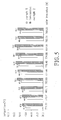
- the experimental results were shown in Fig. 5 , every operating temperature as shown in Fig. 5 was obtained from the average of nine experimental results.
- Fig. 5 supports that the conventional EVA resin layer with a thermal conductivity of 0.32 W/m*K cannot effectively transfer the thermal energy, which is not converted into the electrical energy, to the adjacent silicone sealant or adjacent back-sheet, thereby failing to dissipate the heat generated from the photoelectric conversion element to the environment.
- the thermally conductive encapsulate comprising a thermally conductive composite layer with a thermal conductivity of 0.87 W/m*K and having an overall thermal impedance of 0.36°C-in 2 /W, can effectively transfer the thermal energy to the adjacent back-sheet or transfer the thermal energy to the environment through the thermally conductive sealant and the metal frame. Accordingly, the thermally conductive encapsulate does provide a good heat-transfer path to decrease the operating temperature of the solar cell module.
- the solar cell modules of Example 5 and Comparative example 2 were tested under the identical solar irradiation at an ambient temperature of 29°C to 31°C, and the standard power outputs of the solar cell modules were 230 W per 1.7 square meters.
- the power outputs of the solar cell modules of Example 5 and Comparative example 2 were monitored with a real-time solar monitoring system at various solar irradiations during the time between PM 12:00 and PM 1:00. The experimental results were shown in Fig. 6 .
- Example 5 With reference to Fig. 6 , it demonstrates that most solar cell modules' power outputs in Example 5 are 6.4 W higher than those in Comparative example 2 during the time between PM 12:00 and PM 1:00. Moreover, the total power outputs of the solar cell modules in Example 5 is also 4W higher than that in Comparative example 2.
- the solar cell modules of Examples 4 to 6 and the conventional solar cell module of Comparative example 2 were tested under 1000 W of solar irradiation at an ambient temperature of 31°C to 33°C during the time between AM 10:00 and PM 3:00.
- the power outputs of the solar cell modules of Examples 4 to 6 and Comparative example 2 were monitored with a real-time solar monitoring system.
- the experimental results were listed in Fig. 6 .
- Table 3 the theoretical irradiations, maximum power outputs and total power outputs of the solar cell modules in Examples 4 and 6 and of the conventional solar cell module in Comparative example 2, and the power output difference between the samples and Comparative example 2 Sample No.
- the thermally conductive encapsulate and the thermally conductive sealant can transfer the heat generated by the photoelectric conversion elements to the environment through a lateral pathway from the thermally conductive composite layer, the thermally conductive sealant and the metal frame, thereby improving the heat-dissipating rate and efficiency. Accordingly, all solar cell modules of Examples 4 to 6 have much higher maximum power outputs and much higher total power outputs than those of the Comparative example 2.
- the thermally conductive encapsulates of the solar cell modules in Examples 4 to 6 not only dissipate the thermal energy effectively to maintain a lower operating temperature, but also improve the solar cell module's conversion efficiency to allow higher power outputs.
- the solar cell module comprising the thermally conductive encapsulate is more applicable in the related field.
Landscapes
- Photovoltaic Devices (AREA)
Description
- The present invention is related to a semiconductor device technology, particularly to a thermally conductive encapsulate and a solar cell module comprising the same.
- A commonly known solar cell module is composed of a transparent substrate, a first sealing resin layer, photoelectric conversion elements, a second sealing resin layer and a back-sheet from the top to bottom. The photoelectric conversion elements are enclosed by the first and the second sealing resin layers to be isolated from the moisture in the exterior environment
-
US 2010/043871 A1 discloses a solar panel (10) comprising a transparent substrate (12), a sealing resin layer (14) disposed on the transparent substrate (12), a photoelectric conversion element (16) disposed on the sealing resin layer (14), a thermally conductive composite layer (18) disposed on the photoelectric conversion element and the sealing resin layer. - However, the conventional solar cell modules convert merely 14% to 22% of light energy into electricity, and the rest of the energy is reflected to the environment or converted into heat and increases the operating temperature of the solar cell module, thereby decreasing the conversion efficiency of the solar cell module.
- To overcome the foregoing problems, an improved solar cell module comprising a heat sink mounted on the back-sheet is provided. With the multiple extension parts of the heat sink, the heat-dissipation area of the solar cell module is increased, thereby reducing the solar cell module's operating temperature. However, the improved solar cell module has several problems:
- (1) Modification of original encapsulation process is required, such that the improved solar cell module is not convenient for mass production.
- (2) The applicability of the solar cell module is restricted by the increased volume and thickness.
- (3) Heat generated from the photoelectric conversion element cannot be transferred to the heat sinks through the second sealing resin layer and the back-sheet since the photoelectric conversion element is enclosed by two sealing resin layer with relatively low thermal conductivity. Therefore, mounting the heat sinks at the exteriors of the solar cell module is useless for reducing the solar cell module's operating temperature.
- To overcome the foregoing shortcomings, an objective of the present invention is to provide an effective pathway for dissipating the heat of the photoelectric conversion element to the environment, thereby decreasing the solar cell module's operating temperature and enhancing its conversion efficiency and power output as well.
- Another objective of the present invention is to mitigate the aging of the interior elements in the solar cell module at the higher operating temperature for long time period instead of increasing the solar cell module's size or modifying the encapsulation process of the solar cell module.
- To achieve the foregoing objective, the present invention provides a thermally conductive encapsulate comprising a thermally conductive composite layer and an adhesive resin layer. The thermally conductive composite layer includes a thermoplastic resin and inorganic powders dispersed in the thermoplastic resin in an amount of 40 vol% to 70 vol% based on the volume of the thermally conductive composite layer, and the thermally conductive composite layer has a thermal conductivity ranging from 0.5 W/m*K to 8 W/m*K. Said adhesive resin layer is disposed on the thermally conductive composite layer and has a thermal conductivity ranging from 0.05 W/m*K to 0.4 W/m*K. A percentage of a thickness of the adhesive resin layer relative to a total thickness of the thermally conductive encapsulate ranges from 0.1% to 10%, and the thermally conductive encapsulate comprising the thermally conductive composite layer and the adhesive resin layer has an overall thermal impedance ranging from 0.01 °C*in2/W to 0.72 °C*in2/W.
- In accordance with the present invention, the overall thermal impedance of the thermally conductive encapsulate is reduced to less than 0.72 °C-in2/W by controlling (1) the amount of the inorganic powders and (2) the ratio of the adhesive resin layer relative to the thermally conductive composite layer and the adhesive resin layer in thickness at the same time. Hence, applying the thermally conductive encapsulate to a solar cell module is useful for dissipating the heat generated from the photoelectric conversion element, whereby the aging effect of the solar cell module and undesired increase of operating temperature are mitigated, such that the solar cell comprising the thermally conductive encapsulate provides a path of heat dispersed to the heat sink, which improves conversion efficiency and increases power output.
- Said total thickness of the thermally conductive encapsulate is directed to the sum of the thermally conductive composite layer's thickness and the adhesive resin layer's thickness.
- Preferably, a hot melting process or a wet coating process may be used to form the adhesive resin layer on the thermally conductive composite layer.
- Preferably, the amount of the inorganic powders ranges from 20 vol% to 70 vol% based on the volume of the thermally conductive composite layer.
- Preferably, the thermoplastic resin of the thermally conductive composite layer has a thermal conductivity from 0.05 W/m*K to 0.4 W/m*K.
- Preferably, the total thickness of the thermally conductive encapsulate ranges from 20 micrometers to 600 micrometers.
- Preferably, in the thermally conductive encapsulate, the thermally conductive encapsulate has an overall thermal impedance ranging from 0.01 °C-in2/W to 0.72° C-in2/W. In a more feasible embodiment, the thermally conductive encapsulate has an overall thermal impedance ranging from 0.1 °C-in2/W to 0.72 °C-in2/W.
- Preferably, said thermally conductive encapsulate has a volume resistivity higher than 1.0×10¹⁴ Ω*cm, 22 kV/mm of insulation breakdown voltage, an insulation moisture absorption at insulation breakdown voltage (20°C/24 hours) less than 0.1%, a longitudinal shrinkage less than 3% and a transverse shrinkage less than 1.0 % (120°C/3 minutes, measured by ASTM D1204).
- The present invention also provides a solar cell module, which comprises a transparent substrate, a sealing resin layer, a photoelectric conversion element, a thermally conductive encapsulate as mentioned above and a back-sheet. The sealing resin layer is disposed on the transparent substrate, and the photoelectric conversion element is disposed on the sealing resin layer. The thermally conductive encapsulate is disposed on the photoelectric conversion element and the sealing resin layer, the adhesive resin layer of the thermally conductive encapsulate contacts the photoelectric conversion element, and the back-sheet is disposed on the thermally conductive composite layer of the thermally conductive encapsulate.
- Preferably, the solar cell module comprises another thermally conductive composite layer disposed at exteriors of the thermally conductive encapsulate and the back-sheet and in contact with the photoelectric conversion element. Accordingly, heat generated by the photoelectric conversion element is conducted out of the solar cell module by said another thermally conductive composite layer directly or in combination with the thermally conductive composite layer of the thermally conductive encapsulate, such that the operating temperature of the solar cell module can be decreased.
- Preferably, the solar cell module comprises a thermally conductive sealant and a metal frame, the metal frame is bonded to exteriors of the transparent substrate, the sealing resin layer, the thermally conductive encapsulate and the back-sheet by the thermally conductive sealant. With this configuration, heat generated by the photoelectric conversion element can be conducted through a dissipation pathway from the thermally conductive composite layer, the thermally conductive sealant and the metal frame and finally out of the solar cell module to decrease the solar cell module's operating temperature.
- More preferably, the solar cell module comprises another thermally conductive composite layer disposed between the thermally conductive sealant and the thermally conductive encapsulate and between the thermally conductive sealant and the back-sheet, and said another thermally conductive composite layer is in contact with the photoelectric conversion element. Therefore, heat generated by the photoelectric conversion element also can be conducted to the environment by said another thermally conductive composite layer directly or through a dissipation pathway from the thermally conductive composite layer, the thermally conductive sealant and the metal frame, so as to decrease the solar cell module's operating temperature.
- Preferably, said another thermally conductive composite layer comprises a thermoplastic resin and inorganic powders dispersed in the thermoplastic resin of said another thermally conductive composite layer in an amount of 10 vol% to 70 vol% based on the volume of said another thermally conductive composite layer, whereby said another thermally conductive composite layer has a thermal conductivity ranging from 0.5 W/m*K to 8 W/m*K. More preferably, the amount of the inorganic powders of said another thermally conductive composite ranges from 20 vol% to 70 vol% based on the volume of said another thermally conductive composite layer.
- Preferably, the thermally conductive sealant has a thermal conductivity ranging from 0.05 W/m*K to 0.4 W/m*K.
- In accordance with the present invention, the adhesive resin layer includes a thermoplastic resin. Said thermoplastic resin included in the adhesive resin layer, in the thermally conductive composite layer or in said another thermally conductive composite layer may be polyolefins, such as, but not limited to, poly(ethylene-co-propylene), poly(propylene-co-ethylene), polyethylene ionomer, ethylene-ethylene vinyl acetate copolymer or cross-linked polyethylene. More specifically, the thermoplastic resin may be, but not limited to, ethylene-acrylate copolymer resin, ethylene-glycerin copolymer resin, ethylene-vinyl acetate copolymer resin (EVA), polyvinyl butyral (PVB), thermoplastic polyurethane (TPU) or polyethylene-glycidyl methacrylate (EGMA).
- Said adhesive resin layer or the sealing resin layer may include an adhesive material such as silicone resin or hot melt adhesive.
- Said sealing resin layer has a light transmittance more than 92% and includes a material such as ethylene-acrylate copolymer resin, ethylene-glycerin copolymer resin, ethylene-vinyl acetate copolymer resin, polyvinyl butyral, thermoplastic polyurethane or polyethylene-glycidyl methacrylate.
- Said transparent substrate has a light transmittance more than 92%, and may be a glass substrate.
- Said photoelectric conversion element may be a monocrystalline silicon cell or a polycrystalline silicon chip.
- Said back-sheet is a plastic sheet with good weather resistance and good insulating property, which may be made of polyvinyl fluoride (PVF) or polyethylene terephthalate (PET).
- Preferably, the inorganic powders have a median particle size equal to or less than 20 micrometers; more preferably, ranging from 1 micrometer to 20 micrometers.
- Even more preferably, the inorganic powders have a median particle size ranging from 1 micrometer to 3 micrometers to be well-dispersed in the thermoplastic resin. Accordingly, a thermally conductive composite layer or another thermally conductive composite layer comprising the inorganic powders obtains a higher thermal conductivity.
- Preferably, the inorganic powders may be made of a material such as inorganic oxide, inorganic nitride or any combination thereof. More specifically, the material of the inorganic powders includes aluminum oxide (Al2O3), aluminum nitride (AlN), boron nitride (BN), silicon carbide or any combination thereof. More preferably, the material of the inorganic powders is boron nitride or aluminum nitride.
- In the encapsulation process of the solar cell module, the substrate, the sealing resin layer, the photoelectric conversion element, the thermally conductive encapsulate and the back-sheet are stacked into a laminated structure, then a metal frame loaded with silicone resin sealant or a hot melt adhesive is used to encapsulate the laminated structure. After installation of a junction box and conductive wires, an encapsulated solar cell module is obtained. Optionally, the substrate, the sealing resin layer, the photoelectric conversion element, the thermally conductive encapsulate and the back-sheet also can be enclosed and sealed by a sealing tape, such as acrylic foaming tape, polyethylene foaming tape or butyl rubber foaming tape, to form a laminated structure, and the laminated structure is then pressed into the metal frame to obtain an encapsulated solar cell module.
- In conclusion, the thermally conductive encapsulate is capable of having an overall thermal impedance less than 0.72 °C-in2/W when (1) the amount of the inorganic powders ranges from 10 vol% to 70 vol% based on the volume of the thermally conductive composite layer and (2) the percentage of the adhesive resin layer relative to the thermally conductive composite layer and the adhesive resin layer ranges from 0.1 % to 10% in thickness. The thermally conductive encapsulate of the present invention not only provides sealing, insulating and adhesive properties same as the conventional sealing layer, but also dissipates the heat generated from the photoelectric conversion element to the environment effectively without increasing the thickness or volume of the solar cell module and without modifying the original encapsulation process. Accordingly, the decreased operating temperature of the solar cell module is beneficial to mitigate the aging of the interior elements in the solar cell module at the higher operating temperature and to improve the solar cell module's conversion efficiency and power output.
- Other objectives, advantages and novel features of the invention will become more apparent from the following detailed description when taken in conjunction with the accompanying drawings and tables.
-
-
Fig. 1 is a schematic view of Examples 1 to 3 of thermally conductive encapsulates in accordance with the present invention; -
Fig. 2 illustrates the thermal conductivities of a conventional sealing layer and the thermally conductive encapsulates of Examples 1 and 3; -
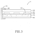
Fig. 3 is a schematic view of Examples 4 to 6 of solar cell modules in accordance with the present invention; -
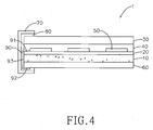
Fig. 4 is a schematic view of Example 7 of a solar cell module in accordance with the present invention; -
Fig. 5 illustrates the operating temperatures of the solar cell modules of Examples 5 and Comparative example 2 at various solar irradiations; and -
Fig. 6 illustrates the power output generated by the solar cell modules of Examples 5 and Comparative example 2 at various solar irradiations. - Hereinafter, one skilled in the arts can easily realize the advantages and effects of a thermally conductive encapsulate and a solar cell module comprising the same in accordance with the present invention from the following examples and tables. The descriptions proposed herein are just preferable examples for the purpose of illustrations only, not intended to limit the scope of the invention. Various modifications and variations could be made in order to practice or apply the present invention without departing from the spirit and scope of the invention.
- Raw material:
- 1. Ethylene methacrylic acid resin with a melting index (MI) of 8 at 190°C and having a thermal conductivity of 0.32 W/m*K, as a thermoplastic resin; and
- 2. Aluminum oxide powders having a median particle size about 5 micrometers, as inorganic powders.
- The ethylene methacrylic acid resin and aluminum oxide powders were mixed by a twin screw extruder with various ratios listed in Table 1 to obtain the thermally conductive composite masterbatches of Preparation examples 1 to 4. The thermal conductivities of thermally conductive composite masterbatches were measured with a thermal conductivity meter according to the ASTM E1461, the results were listed in Table 1.
Table 1: the amounts of aluminum oxide (Al2O3) and ethylene methacrylic acid resin (EMA resin) based on the volume of the thermally conductive resin masterbatch (unit: volume percent (vol%)) and the thermal conductivity of the thermally conductive resin masterbatch in Preparation examples 1 to 4 Preparation examples No. amount of Al2O3 amount of EMA resin thermal conductivity of the thermally conductive resin masterbatch 1 0 vol% 100 vol% 0.32 W/m*K 2 40 vol% 60 vol% 0.59 W/m*K 3 60 vol% 40 vol% 0.87 W/m* K 4 80 vol% 20 vol% 1.51 W/m*K - As shown in Table 1, the thermal conductivities of the thermally conductive resin masterbatches were increased from 0.32 W/m*K (Preparation example 1) to 1.51 W/m*K (Preparation example 4) as the amounts of the aluminum oxides content increased.
- In the comparative example, the conventional sealing layer was made of pure EMA resin without any inorganic powders. The pure EMA resin was directly formed into a 15 cm* 15 cm and 220 µm-thick conventional sealing layer by blown film extrusion. The thermal impedance of the conventional sealing layer was listed in below Table 2.
- The thermally conductive resin masterbatches obtained from Preparation examples 2 to 4 were used to prepare the thermally conductive encapsulates of Examples 1 to 3. Said thermally conductive encapsulates were prepared by a similar method as follows.
- A thermally conductive resin masterbatch was formed into a 15 cm* 15 cm and 200 µm-thick thermally conductive composite layer by blown film extrusion. Then a 20 µm-thick EGMA resin layer, as an adhesive resin layer, was formed on the thermally conductive composite layer by hot melting, so as to obtain a thermally conductive encapsulate.
- With reference to
Fig. 1 , the thermally conductive encapsulate prepared from the aforementioned method comprises a thermally conductive composite layer (10) and an adhesive resin layer (20). - The thermally conductive composite layer (10) comprises a thermoplastic resin (101) and multiple inorganic powders (102) dispersed in the thermoplastic resin (101). The adhesive resin layer (20) is disposed on the thermally conductive composite layer (10) and has a thermal conductivity of 0.27 W/m*K.
- By means of adding the inorganic powders in the thermally conductive encapsulates of Examples 1 to 3, the thermally conductive encapsulates comprising the thermally conductive composite layers (10) and adhesive resin layers (20) have overall thermal impedances less than 0.72 °C-in2/W, respectively.
- Table 2: the thermally conductive resin masterbatches used in Examples 1 to 3 and Comparative example 1 and their thermal impedances
Table 2 thermally conductive resin masterbatch the overall thermal impedance of the thermally conductive encapsulate Comparative example 1 Preparation example 1 1.06 °C*in2/W Example 1 Preparation example 2 0.64 °C*in2/W Example 2 Preparation example 3 0.47 °C*in2/W Example 3 Preparation example 4 0.32 °C*in2/W - In the instant testing example, a back-sheet, a thermally conductive encapsulate of Examples 2 or 4 or a conventional sealing layer of Comparative example 1, a sealing resin layer and a transparent glass substrate were stacked in sequence to obtain a laminated sample for determining the thermal conductance of the thermally conductive encapsulate.
- To ensure the significance of the experimental results, all laminated samples had identical back-sheet, identical sealing resin layer and identical transparent glass substrate in thickness and in material, and were tested by the same method and under the same environment. Thus, the thermal conductance of the laminated samples was directed to the thermal conductance of the conventional sealing layer and the thermally conductive encapsulate of Examples 1 and 3. Detailed experimental method was as follows.
- An identical heat source was mounted on the transparent glass substrates of the laminated samples at a distance of 20 centimeters from each transparent glass substrate to heat the transparent glass substrates in a heating area about 10 square centimeters respectively. The thermal conduction time of each laminated sample was determined by the fact that the conventional sealing layer or the thermally conductive encapsulate started to transfer the thermal energy from the transparent glass substrate to the back-sheet until the temperature of back-sheet was increased to 30°C. The temperature of back-sheet was measured by infrared detector.
- With reference to
Fig. 2 , the heat conduction time of the conventional sealing layer required almost 300 seconds; however, the thermal conduction time of the thermally conductive encapsulate only required 250 seconds, and even 90 to 100 seconds. It reveals that the thermally conductive encapsulates of Examples 1 and 3 do provide an excellent thermal conductance. - The solar cell modules of Examples 4 to 6 respectively comprised the thermally conductive encapsulates of Examples 1 to 3, and all solar cell modules were prepared by a similar method as follows.
- First, a transparent glass substrate, an EVA resin layer, an array of 72 monocrystalline silicon cells (purchased by Motech Industries, Inc.), 220 µm-thick thermally conductive encapsulate and polyester series back-sheet were stacked in sequence, the EVA resin layer was pressed at 140°C for thermal setting until a cross-linking density of 85%, so as to obtain a laminated structure.
- Then a thermally conductive silicone resin sealant containing aluminum oxides were injected into the gaps of metal frame to obtain an aluminum frame loaded with the thermally conductive silicon resin sealant.
- After that, the laminated structure was enclosed by the aluminum frame loaded with thermally conductive silicone resin sealant and then aged to complete the encapsulation process of the solar cell module.
- According to the method as mentioned above, the solar cell modules of Examples 4 to 6 have a similar structure as shown in
Fig. 3 , the difference between the Examples are the materials of the thermally conductive composite layers. - With reference to
Fig. 3 , the solar cell module (1) comprises a thermally conductive composite layer (10) as shown inFig. 1 , an adhesive resin layer (20), a transparent substrate (30), a sealing resin layer (40), multiple photoelectric conversion elements (50), a back-sheet (60), a metal frame (70) and a thermally conductive sealant (80). - The transparent substrate (30) is a 3mm-thick transparent glass substrate having a light transmittance more than 92%.
- The sealing resin layer (40) is an EVA resin layer, which is disposed on the transparent substrate (30) and has a thickness about 450 micrometers and a thermal conductivity of 0.32 W/m*K.
- The photoelectric conversion elements (50) are 72 monocrystalline silicon cells each having a thickness of 180 micrometers and two opposite surfaces. The photoelectric conversion elements (50) are arranged on the sealing resin layer (40) to form an array.
- The adhesive resin layer (20) is a 20 µm-thick EGMA resin layer, a portion of the adhesive resin layer (20) is directly adhered to the surface of the photoelectric conversion elements (50), and the rest of the adhesive resin layer (20) is directly adhered to the bottom surface of the sealing resin layer (40) not in contact with the photoelectric conversion elements (50). One surface of each photoelectric conversion element (50) is adhered with the sealing resin layer (40) and the other surface of the photoelectric conversion element (50) is adhered with the adhesive resin layer (20). Accordingly, each and every photoelectric conversion element (50) is sealed by the adhesive resin layer (20) and the sealing resin layer (40), such that the photoelectric conversion elements (50) are fully isolated from the moisture in the external environments.
- The thermally conductive composite layer (10) is a composite layer, which is manufactured by EMA resin compound with aluminum oxide powder and has a thickness of 200 micrometers. Said thermally conductive composite layer (10) is attached onto the surface of the adhesive resin layer (20) opposite to the photoelectric conversion elements (50).
- The back-sheet (60) is a 350 µm-thick polyester series back-sheet and has a thermal conductivity of 0.28 W/m*K. The thermally conductive composite layer (10) is disposed between the adhesive resin layer (20) and the back-sheet (60).
- The metal frame (70) is a heat-dissipation aluminum frame having a groove structure. A thermally conductive sealant (80) is injected into the groove structure of the metal frame (70), and the metal frame (70) is bonded to exteriors of the transparent substrate (30), the sealing resin layer (40), the adhesive rein layer (20), the thermally conductive composite layer (10) and the back-sheet by the thermally conductive sealant (80). Herein, the thermally conductive sealant (80) is made of a silicone resin compound with aluminum oxide and has a thermal conductivity of 1.0 W/m*K.
- With reference to
Fig. 4 , the solar cell module (1) has a similar structure with those of Examples 4 to 6 and comprises a thermally conductive composite layer (10), an adhesive resin layer (20), a transparent substrate (30), a sealing resin layer (40), multiple photoelectric conversion elements (50), a back-sheet (60), a metal frame (70) and a thermally conductive sealant (80). The difference between the instant example and the Examples 4 to 6 is that the solar cell module (1) further comprises another thermally conductive composite layer (90), which is made of a material identical to that of the thermally conductive composite layer (10). - Said another thermally conductive composite layer (90) is interposed between the thermally conductive composite layer (10) and the thermally conductive sealant (80), between the adhesive resin layer (20) and the thermally conductive sealant (80), between the thermally conductive sealant (80) and the back-sheet (60), and is in contact with the photoelectric conversion element (50).
- More specifically, said another thermally conductive composite layer (90) has two thermally conductive extension parts (91), (92) and a thermally conductive main part (93) formed between the thermally conductive extension parts (91), (92). The thermally conductive extension part (91) directly contacts the photoelectric conversion element (50) and is interposed between the sealing resin layer (40) and the adhesive resin layer (20). The thermally conductive main part (93) is mounted on the side surfaces of the thermally conductive encapsulate and of the back-sheet (60), and is interposed between the thermally conductive composite layer (10) and thermally conductive sealant (80), between the adhesive resin layer (20) and the thermally conductive sealant (80), and between the thermally conductive sealant (80) and the back-sheet (60). The thermally conductive main part (93) is interposed between the bottom surface of the back-sheet (60) and the thermally conductive sealant (80).
- In the comparative example, a single EVA resin layer is used to replace the thermally conductive composite layer and the adhesive resin layer in the solar cell module of Example 4. Said EVA resin layer is interposed between the photoelectric conversion elements and the back-sheet, and the photoelectric conversion elements are sealed and enclosed by the EVA resin layer and the sealing resin layer. Furthermore, a silicone sealant with a thermal conductivity only 0.36 W/m*K is also used to replace the thermally conductive sealant of Example 4.
- To verify that the thermally conductive encapsulate is useful for reducing the operating temperature of the solar cell module, the solar cell modules of Example 5 and Comparative example 2 were tested exposed to the identical solar irradiation at an ambient temperature of 29°C to 31°C, and the standard power outputs of the solar cell modules were 230 W per 1.7 square meters. The operating temperatures of the solar cell modules of Example 5 and Comparative example 2 were monitored with an infrared thermometer at various solar irradiations during the time between PM 12:00 and PM 1:00. The experimental results were shown in
Fig. 5 , every operating temperature as shown inFig. 5 was obtained from the average of nine experimental results. -
Fig. 5 supports that the conventional EVA resin layer with a thermal conductivity of 0.32 W/m*K cannot effectively transfer the thermal energy, which is not converted into the electrical energy, to the adjacent silicone sealant or adjacent back-sheet, thereby failing to dissipate the heat generated from the photoelectric conversion element to the environment. On the contrary, the thermally conductive encapsulate, comprising a thermally conductive composite layer with a thermal conductivity of 0.87 W/m*K and having an overall thermal impedance of 0.36°C-in2/W, can effectively transfer the thermal energy to the adjacent back-sheet or transfer the thermal energy to the environment through the thermally conductive sealant and the metal frame. Accordingly, the thermally conductive encapsulate does provide a good heat-transfer path to decrease the operating temperature of the solar cell module. - To verify that the thermally conductive encapsulate is useful for improving the solar cell module's power outputs, the solar cell modules of Example 5 and Comparative example 2 were tested under the identical solar irradiation at an ambient temperature of 29°C to 31°C, and the standard power outputs of the solar cell modules were 230 W per 1.7 square meters. The power outputs of the solar cell modules of Example 5 and Comparative example 2 were monitored with a real-time solar monitoring system at various solar irradiations during the time between PM 12:00 and PM 1:00. The experimental results were shown in
Fig. 6 . - With reference to
Fig. 6 , it demonstrates that most solar cell modules' power outputs in Example 5 are 6.4 W higher than those in Comparative example 2 during the time between PM 12:00 and PM 1:00. Moreover, the total power outputs of the solar cell modules in Example 5 is also 4W higher than that in Comparative example 2. - In the testing example, the solar cell modules of Examples 4 to 6 and the conventional solar cell module of Comparative example 2 were tested under 1000 W of solar irradiation at an ambient temperature of 31°C to 33°C during the time between AM 10:00 and PM 3:00. The power outputs of the solar cell modules of Examples 4 to 6 and Comparative example 2 were monitored with a real-time solar monitoring system. The experimental results were listed in
Fig. 6 .Table 3: the theoretical irradiations, maximum power outputs and total power outputs of the solar cell modules in Examples 4 and 6 and of the conventional solar cell module in Comparative example 2, and the power output difference between the samples and Comparative example 2 Sample No. theoretical irradiation under 1000 W maximum power output total power output during the time between AM10:00 and PM 3:00 power output difference Comparative example 2 235.489W 163.9 W 37418.9 W 0 Example 4 235.871W 164.6 W 37470.2 W 51.3W Example 6 235.711W 169.3 W 37984.1 W 565.2W - As shown in Table 3, the thermally conductive encapsulate and the thermally conductive sealant can transfer the heat generated by the photoelectric conversion elements to the environment through a lateral pathway from the thermally conductive composite layer, the thermally conductive sealant and the metal frame, thereby improving the heat-dissipating rate and efficiency. Accordingly, all solar cell modules of Examples 4 to 6 have much higher maximum power outputs and much higher total power outputs than those of the Comparative example 2.
- In conclusion, the thermally conductive encapsulates of the solar cell modules in Examples 4 to 6 not only dissipate the thermal energy effectively to maintain a lower operating temperature, but also improve the solar cell module's conversion efficiency to allow higher power outputs. Thus, the solar cell module comprising the thermally conductive encapsulate is more applicable in the related field.
- Even though numerous characteristics and advantages of the present invention have been set forth in the foregoing description, together with details of the structure and features of the invention, the disclosure is illustrative only. Changes may be made in the details, especially in matters of shape, size, and arrangement of parts within the principles of the invention to the full extent indicated by the broad general meaning of the terms in which the appended claims are expressed.
Claims (15)
- A thermally conductive encapsulate, comprising a thermally conductive composite layer (10) and an adhesive resin layer (20) disposed on the thermally conductive composite layer (10), and the thermally conductive encapsulate characterized in that:the thermally conductive composite layer (10) includes a thermoplastic resin (101) and inorganic powders (102) dispersed in the thermoplastic resin (101) in an amount of 40 vol% to 70 vol% based on a volume of the thermally conductive composite layer (10), the thermally conductive composite layer (10) having a thermal conductivity ranging from 0.5 W/m*K to 8 W/m*K; andthe adhesive resin layer (20) has a thermal conductivity ranging from 0.05 W/m*K to 0.4 W/m*K; anda percentage of a thickness of the adhesive resin layer (20) relative to a total thickness of the thermally conductive encapsulate ranges from 0.1% to 10%, and the thermally conductive encapsulate has an overall thermal impedance ranging from 0.01 °C*in2/W to 0.72 °C*in2/W,wherein the thermal conductivities are measured according to ASTM E1461.
- The thermally conductive encapsulate as claimed in claim 1, wherein the thermoplastic resin (101) of the thermally conductive composite layer (10) has a thermal conductivity ranging from 0.05 W/m*K to 0.4 W/m*K.
- The thermally conductive encapsulate as claimed in claim 1, wherein the inorganic powders (102) have a median particle size equal to or less than 20 micrometers and a material of the inorganic powders (102) includes inorganic oxide, inorganic nitride or any combination thereof.
- The thermally conductive encapsulate as claimed in claim 3, wherein the median particle size of the inorganic powders (102) ranges from 1 micrometer to 3 micrometers, and the material of the inorganic powders (102) includes aluminum oxide, aluminum nitride, boron nitride or any combination thereof.
- The thermally conductive encapsulate as claimed in claim 1, wherein the inorganic powders (102) have a median particle size equal to or less than 20 micrometers, and a material of the inorganic powders (102) includes silicon carbide.
- The thermally conductive encapsulate as claimed in claim 1, wherein the total thickness of the thermally conductive encapsulate ranges from 20 micrometers to 600 micrometers.
- A solar cell module (1), comprising a transparent substrate (30), a sealing resin layer (40) disposed on the transparent substrate (30), a photoelectric conversion element (50) disposed on the sealing resin layer (40), a thermally conductive encapsulate disposed on the photoelectric conversion element (50) and the sealing resin layer (40), the thermally conductive encapsulate comprising a thermally conductive composite layer (10) and an adhesive resin layer (20) disposed between the photoelectric conversion element (50) and the thermally conductive composite layer (10), the adhesive resin layer (20) being in contact with the photoelectric conversion element (50), and a back-sheet (60) disposed on the thermally conductive composite layer (10) of the thermally conductive encapsulate, and the thermally conductive encapsulate characterized in that:
the thermally conductive composite layer (10) includes a thermoplastic resin (101) and inorganic powders (102) dispersed in the thermoplastic resin (101) in an amount of 40 vol% to 70 vol% based on the volume of the thermally conductive composite layer (10), the thermally conductive composite layer (10) having a thermal conductivity ranging from 0.5 W/m*K to 8 W/m*K;
the adhesive resin layer (20) has a thermal conductivity ranging from 0.05 W/m*K to 0.4 W/m*K; and
a percentage of a thickness of the adhesive resin layer (20) relative to a total thickness of the thermally conductive encapsulate ranges from 0.1% to 10%, and the thermally conductive encapsulate has an overall thermal impedance ranging from 0.01 °C*in2/W to 0.72 °C*in2/W,
wherein the thermal conductivities are measured according to ASTM E1461. - The solar cell module (1) as claimed in claim 7, wherein the thermoplastic resin (101) of the thermally conductive composite layer (10) has a thermal conductivity ranging from 0.05 W/m*K to 0.4 W/m*K, and the total thickness of the thermally conductive encapsulate ranges from 20 micrometers to 600 micrometers.
- The solar cell module (1) as claimed in claim 7, wherein the inorganic powders (102) have a median particle size equal to or less than 20 micrometers and a material of the inorganic powders (102) includes inorganic oxide, inorganic nitride or any combination thereof.
- The solar cell module (1) as claimed in claim 9, wherein the median particle size of the inorganic powders (102) ranges from 1 micrometer to 3 micrometers, and the material of the inorganic powders (102) includes aluminum oxide, aluminum nitride, boron nitride or any combination thereof.
- The solar cell module (1) as claimed in claim 7, wherein the inorganic powders (102) have a median particle size equal to or less than 20 micrometers, and a material of the inorganic powders (102) includes silicon carbide.
- The solar cell module (1) as claimed in claim 7, wherein the solar cell module (1) comprises another thermally conductive composite layer (90) disposed at exteriors of the thermally conductive encapsulate and the back-sheet (60) and in contact with the photoelectric conversion element (50).
- The solar cell module (1) as claimed in claim 7, wherein the solar cell module (1) comprises a thermally conductive sealant (80) having a thermal conductivity ranging from 0.05 W/m*K to 0.4 W/m*K and a metal frame (70), the metal frame (70) is bonded to exteriors of the transparent substrate (30), the sealing resin layer (40), the thermally conductive encapsulate and the back-sheet (60) by the thermally conductive sealant (80).
- The solar cell module (1) as claimed in claim 13, wherein the solar cell module (1) comprises another thermally conductive composite layer (90) disposed between the thermally conductive sealant (80) and the thermally conductive encapsulate and between the thermally conductive sealant (80) and the back-sheet (60), and said another thermally conductive composite layer (90) contacts the photoelectric conversion element (50).
- The solar cell module (1) as claimed in claim 12 or 14, wherein said another thermally conductive composite layer (90) comprises a thermoplastic resin and inorganic powders dispersed in the thermoplastic resin of said another thermally conductive composite layer (90) in an amount of 10 vol% to 70 vol% based on the volume of said another thermally conductive composite layer (90), and said another thermally conductive composite layer (90) has a thermal conductivity ranging from 0.5 W/m*K to 8 W/m*K.
Priority Applications (1)
| Application Number | Priority Date | Filing Date | Title |
|---|---|---|---|
| EP14150535.4A EP2894675B1 (en) | 2014-01-09 | 2014-01-09 | Thermally conductive encapsulate and solar cell module comprising the same |
Applications Claiming Priority (1)
| Application Number | Priority Date | Filing Date | Title |
|---|---|---|---|
| EP14150535.4A EP2894675B1 (en) | 2014-01-09 | 2014-01-09 | Thermally conductive encapsulate and solar cell module comprising the same |
Publications (2)
| Publication Number | Publication Date |
|---|---|
| EP2894675A1 EP2894675A1 (en) | 2015-07-15 |
| EP2894675B1 true EP2894675B1 (en) | 2016-10-05 |
Family
ID=49911416
Family Applications (1)
| Application Number | Title | Priority Date | Filing Date |
|---|---|---|---|
| EP14150535.4A Not-in-force EP2894675B1 (en) | 2014-01-09 | 2014-01-09 | Thermally conductive encapsulate and solar cell module comprising the same |
Country Status (1)
| Country | Link |
|---|---|
| EP (1) | EP2894675B1 (en) |
Family Cites Families (3)
| Publication number | Priority date | Publication date | Assignee | Title |
|---|---|---|---|---|
| WO2008014492A2 (en) * | 2006-07-27 | 2008-01-31 | Nanosolar, Inc. | Individually encapsulated solar cells and/or solar cell strings |
| US20100043871A1 (en) * | 2008-04-14 | 2010-02-25 | Bp Corporation North America Inc. | Thermal Conducting Materials for Solar Panel Components |
| ITPD20110116A1 (en) * | 2011-04-13 | 2012-10-14 | M G Lavorazione Materie Plastiche S P A | MULTI-LAYER POLYMER FILM INSULATED FOR CELLS FOR PHOTOVOLTAIC MODULES, AND INTEGRATED PROTECTIVE SHEET, TYPE 'BACKSHEET' OR 'FRONTSHEET' INCLUDING SUCH FILM |
-
2014
- 2014-01-09 EP EP14150535.4A patent/EP2894675B1/en not_active Not-in-force
Also Published As
| Publication number | Publication date |
|---|---|
| EP2894675A1 (en) | 2015-07-15 |
Similar Documents
| Publication | Publication Date | Title |
|---|---|---|
| US20090255571A1 (en) | Thermal Conducting Materials for Solar Panel Components | |
| KR101070871B1 (en) | Solar Cell Back Module | |
| KR20110084218A (en) | Thermally Conductive Materials for Solar Panel Components | |
| CN205112540U (en) | Photovoltaic layer clamp plate | |
| KR101159750B1 (en) | Heat radiating back sheet for photo voltaic module | |
| US9842951B2 (en) | Encapsulants for photovoltaic modules | |
| JP2009170772A (en) | Solar cell backsheet and solar cell module | |
| CN103000728A (en) | Solar cell back panel assembly and solar cell assembly | |
| CN107731947A (en) | Adhesive film for encapsulation of photovoltaic modules, preparation method thereof, and photovoltaic module containing the adhesive film | |
| CN104241424A (en) | Heat dissipation solar cell back membrane | |
| KR101240714B1 (en) | Back sheet for a solar cell having an excellent heat releasing property and the preparing process thereof | |
| CN104201225A (en) | Heat dissipation type solar cell back film | |
| US20150194553A1 (en) | Thermally conductive encapsulate and solar cell module comprising the same | |
| KR20130062539A (en) | Back sheet for a solar cell having an excellent heat releasing property and the preparing process thereof | |
| KR101575177B1 (en) | Solar cell module with internal heat-transfer element | |
| CN202712223U (en) | Laminated type packaging film for solar cell and solar cell back plate or solar cell component by using packaging film | |
| EP2894675A1 (en) | Thermally conductive encapsulate and solar cell module comprising the same | |
| CN104659128B (en) | Solar module comprising a thermally conductive sealing composite layer | |
| KR101602290B1 (en) | Back sheet for solar cell module and solar cell module including the same | |
| CN116376452B (en) | Thermally conductive composite packaging film and photovoltaic module | |
| KR20210103788A (en) | Back sheet for solar cell module | |
| CN102201474A (en) | Solar photoelectric module and manufacturing method thereof | |
| TW201519460A (en) | Heat conduction sealed composite layer and solar module including the same | |
| JP2003069068A (en) | Solar cell module | |
| JP2012009523A (en) | Heat dissipating material of solar cell, and solar cell module |
Legal Events
| Date | Code | Title | Description |
|---|---|---|---|
| PUAI | Public reference made under article 153(3) epc to a published international application that has entered the european phase |
Free format text: ORIGINAL CODE: 0009012 |
|
| 17P | Request for examination filed |
Effective date: 20150429 |
|
| AK | Designated contracting states |
Kind code of ref document: A1 Designated state(s): AL AT BE BG CH CY CZ DE DK EE ES FI FR GB GR HR HU IE IS IT LI LT LU LV MC MK MT NL NO PL PT RO RS SE SI SK SM TR |
|
| AX | Request for extension of the european patent |
Extension state: BA ME |
|
| GRAP | Despatch of communication of intention to grant a patent |
Free format text: ORIGINAL CODE: EPIDOSNIGR1 |
|
| INTG | Intention to grant announced |
Effective date: 20160425 |
|
| GRAS | Grant fee paid |
Free format text: ORIGINAL CODE: EPIDOSNIGR3 |
|
| GRAA | (expected) grant |
Free format text: ORIGINAL CODE: 0009210 |
|
| AK | Designated contracting states |
Kind code of ref document: B1 Designated state(s): AL AT BE BG CH CY CZ DE DK EE ES FI FR GB GR HR HU IE IS IT LI LT LU LV MC MK MT NL NO PL PT RO RS SE SI SK SM TR |
|
| REG | Reference to a national code |
Ref country code: GB Ref legal event code: FG4D |
|
| REG | Reference to a national code |
Ref country code: CH Ref legal event code: EP |
|
| REG | Reference to a national code |
Ref country code: AT Ref legal event code: REF Ref document number: 835284 Country of ref document: AT Kind code of ref document: T Effective date: 20161015 |
|
| REG | Reference to a national code |
Ref country code: IE Ref legal event code: FG4D |
|
| REG | Reference to a national code |
Ref country code: DE Ref legal event code: R096 Ref document number: 602014004013 Country of ref document: DE |
|
| REG | Reference to a national code |
Ref country code: FR Ref legal event code: PLFP Year of fee payment: 4 |
|
| REG | Reference to a national code |
Ref country code: NL Ref legal event code: MP Effective date: 20161005 |
|
| REG | Reference to a national code |
Ref country code: LT Ref legal event code: MG4D |
|
| PG25 | Lapsed in a contracting state [announced via postgrant information from national office to epo] |
Ref country code: LV Free format text: LAPSE BECAUSE OF FAILURE TO SUBMIT A TRANSLATION OF THE DESCRIPTION OR TO PAY THE FEE WITHIN THE PRESCRIBED TIME-LIMIT Effective date: 20161005 |
|
| PG25 | Lapsed in a contracting state [announced via postgrant information from national office to epo] |
Ref country code: NO Free format text: LAPSE BECAUSE OF FAILURE TO SUBMIT A TRANSLATION OF THE DESCRIPTION OR TO PAY THE FEE WITHIN THE PRESCRIBED TIME-LIMIT Effective date: 20170105 Ref country code: GR Free format text: LAPSE BECAUSE OF FAILURE TO SUBMIT A TRANSLATION OF THE DESCRIPTION OR TO PAY THE FEE WITHIN THE PRESCRIBED TIME-LIMIT Effective date: 20170106 Ref country code: LT Free format text: LAPSE BECAUSE OF FAILURE TO SUBMIT A TRANSLATION OF THE DESCRIPTION OR TO PAY THE FEE WITHIN THE PRESCRIBED TIME-LIMIT Effective date: 20161005 Ref country code: SE Free format text: LAPSE BECAUSE OF FAILURE TO SUBMIT A TRANSLATION OF THE DESCRIPTION OR TO PAY THE FEE WITHIN THE PRESCRIBED TIME-LIMIT Effective date: 20161005 |
|
| PG25 | Lapsed in a contracting state [announced via postgrant information from national office to epo] |
Ref country code: ES Free format text: LAPSE BECAUSE OF FAILURE TO SUBMIT A TRANSLATION OF THE DESCRIPTION OR TO PAY THE FEE WITHIN THE PRESCRIBED TIME-LIMIT Effective date: 20161005 Ref country code: NL Free format text: LAPSE BECAUSE OF FAILURE TO SUBMIT A TRANSLATION OF THE DESCRIPTION OR TO PAY THE FEE WITHIN THE PRESCRIBED TIME-LIMIT Effective date: 20161005 Ref country code: HR Free format text: LAPSE BECAUSE OF FAILURE TO SUBMIT A TRANSLATION OF THE DESCRIPTION OR TO PAY THE FEE WITHIN THE PRESCRIBED TIME-LIMIT Effective date: 20161005 Ref country code: IS Free format text: LAPSE BECAUSE OF FAILURE TO SUBMIT A TRANSLATION OF THE DESCRIPTION OR TO PAY THE FEE WITHIN THE PRESCRIBED TIME-LIMIT Effective date: 20170205 Ref country code: PL Free format text: LAPSE BECAUSE OF FAILURE TO SUBMIT A TRANSLATION OF THE DESCRIPTION OR TO PAY THE FEE WITHIN THE PRESCRIBED TIME-LIMIT Effective date: 20161005 Ref country code: FI Free format text: LAPSE BECAUSE OF FAILURE TO SUBMIT A TRANSLATION OF THE DESCRIPTION OR TO PAY THE FEE WITHIN THE PRESCRIBED TIME-LIMIT Effective date: 20161005 Ref country code: BE Free format text: LAPSE BECAUSE OF FAILURE TO SUBMIT A TRANSLATION OF THE DESCRIPTION OR TO PAY THE FEE WITHIN THE PRESCRIBED TIME-LIMIT Effective date: 20161005 Ref country code: RS Free format text: LAPSE BECAUSE OF FAILURE TO SUBMIT A TRANSLATION OF THE DESCRIPTION OR TO PAY THE FEE WITHIN THE PRESCRIBED TIME-LIMIT Effective date: 20161005 Ref country code: PT Free format text: LAPSE BECAUSE OF FAILURE TO SUBMIT A TRANSLATION OF THE DESCRIPTION OR TO PAY THE FEE WITHIN THE PRESCRIBED TIME-LIMIT Effective date: 20170206 |
|
| REG | Reference to a national code |
Ref country code: DE Ref legal event code: R097 Ref document number: 602014004013 Country of ref document: DE |
|
| PG25 | Lapsed in a contracting state [announced via postgrant information from national office to epo] |
Ref country code: CZ Free format text: LAPSE BECAUSE OF FAILURE TO SUBMIT A TRANSLATION OF THE DESCRIPTION OR TO PAY THE FEE WITHIN THE PRESCRIBED TIME-LIMIT Effective date: 20161005 Ref country code: SK Free format text: LAPSE BECAUSE OF FAILURE TO SUBMIT A TRANSLATION OF THE DESCRIPTION OR TO PAY THE FEE WITHIN THE PRESCRIBED TIME-LIMIT Effective date: 20161005 Ref country code: RO Free format text: LAPSE BECAUSE OF FAILURE TO SUBMIT A TRANSLATION OF THE DESCRIPTION OR TO PAY THE FEE WITHIN THE PRESCRIBED TIME-LIMIT Effective date: 20161005 Ref country code: EE Free format text: LAPSE BECAUSE OF FAILURE TO SUBMIT A TRANSLATION OF THE DESCRIPTION OR TO PAY THE FEE WITHIN THE PRESCRIBED TIME-LIMIT Effective date: 20161005 Ref country code: DK Free format text: LAPSE BECAUSE OF FAILURE TO SUBMIT A TRANSLATION OF THE DESCRIPTION OR TO PAY THE FEE WITHIN THE PRESCRIBED TIME-LIMIT Effective date: 20161005 |
|
| PLBE | No opposition filed within time limit |
Free format text: ORIGINAL CODE: 0009261 |
|
| STAA | Information on the status of an ep patent application or granted ep patent |
Free format text: STATUS: NO OPPOSITION FILED WITHIN TIME LIMIT |
|
| PG25 | Lapsed in a contracting state [announced via postgrant information from national office to epo] |
Ref country code: IT Free format text: LAPSE BECAUSE OF FAILURE TO SUBMIT A TRANSLATION OF THE DESCRIPTION OR TO PAY THE FEE WITHIN THE PRESCRIBED TIME-LIMIT Effective date: 20161005 Ref country code: BG Free format text: LAPSE BECAUSE OF FAILURE TO SUBMIT A TRANSLATION OF THE DESCRIPTION OR TO PAY THE FEE WITHIN THE PRESCRIBED TIME-LIMIT Effective date: 20170105 Ref country code: SM Free format text: LAPSE BECAUSE OF FAILURE TO SUBMIT A TRANSLATION OF THE DESCRIPTION OR TO PAY THE FEE WITHIN THE PRESCRIBED TIME-LIMIT Effective date: 20161005 |
|
| REG | Reference to a national code |
Ref country code: CH Ref legal event code: PL |
|
| 26N | No opposition filed |
Effective date: 20170706 |
|
| PG25 | Lapsed in a contracting state [announced via postgrant information from national office to epo] |
Ref country code: MC Free format text: LAPSE BECAUSE OF FAILURE TO SUBMIT A TRANSLATION OF THE DESCRIPTION OR TO PAY THE FEE WITHIN THE PRESCRIBED TIME-LIMIT Effective date: 20161005 |
|
| PG25 | Lapsed in a contracting state [announced via postgrant information from national office to epo] |
Ref country code: CH Free format text: LAPSE BECAUSE OF NON-PAYMENT OF DUE FEES Effective date: 20170131 Ref country code: LI Free format text: LAPSE BECAUSE OF NON-PAYMENT OF DUE FEES Effective date: 20170131 |
|
| REG | Reference to a national code |
Ref country code: IE Ref legal event code: MM4A |
|
| PG25 | Lapsed in a contracting state [announced via postgrant information from national office to epo] |
Ref country code: SI Free format text: LAPSE BECAUSE OF FAILURE TO SUBMIT A TRANSLATION OF THE DESCRIPTION OR TO PAY THE FEE WITHIN THE PRESCRIBED TIME-LIMIT Effective date: 20161005 Ref country code: LU Free format text: LAPSE BECAUSE OF NON-PAYMENT OF DUE FEES Effective date: 20170109 |
|
| REG | Reference to a national code |
Ref country code: FR Ref legal event code: PLFP Year of fee payment: 5 |
|
| PG25 | Lapsed in a contracting state [announced via postgrant information from national office to epo] |
Ref country code: IE Free format text: LAPSE BECAUSE OF NON-PAYMENT OF DUE FEES Effective date: 20170109 |
|
| GBPC | Gb: european patent ceased through non-payment of renewal fee |
Effective date: 20180109 |
|
| PG25 | Lapsed in a contracting state [announced via postgrant information from national office to epo] |
Ref country code: MT Free format text: LAPSE BECAUSE OF NON-PAYMENT OF DUE FEES Effective date: 20170109 |
|
| PG25 | Lapsed in a contracting state [announced via postgrant information from national office to epo] |
Ref country code: GB Free format text: LAPSE BECAUSE OF NON-PAYMENT OF DUE FEES Effective date: 20180109 |
|
| REG | Reference to a national code |
Ref country code: AT Ref legal event code: UEP Ref document number: 835284 Country of ref document: AT Kind code of ref document: T Effective date: 20161005 |
|
| PGFP | Annual fee paid to national office [announced via postgrant information from national office to epo] |
Ref country code: FR Payment date: 20181212 Year of fee payment: 6 |
|
| PGFP | Annual fee paid to national office [announced via postgrant information from national office to epo] |
Ref country code: DE Payment date: 20190125 Year of fee payment: 6 |
|
| PGFP | Annual fee paid to national office [announced via postgrant information from national office to epo] |
Ref country code: AT Payment date: 20181219 Year of fee payment: 6 |
|
| PG25 | Lapsed in a contracting state [announced via postgrant information from national office to epo] |
Ref country code: HU Free format text: LAPSE BECAUSE OF FAILURE TO SUBMIT A TRANSLATION OF THE DESCRIPTION OR TO PAY THE FEE WITHIN THE PRESCRIBED TIME-LIMIT; INVALID AB INITIO Effective date: 20140109 |
|
| PG25 | Lapsed in a contracting state [announced via postgrant information from national office to epo] |
Ref country code: CY Free format text: LAPSE BECAUSE OF FAILURE TO SUBMIT A TRANSLATION OF THE DESCRIPTION OR TO PAY THE FEE WITHIN THE PRESCRIBED TIME-LIMIT Effective date: 20161005 |
|
| PG25 | Lapsed in a contracting state [announced via postgrant information from national office to epo] |
Ref country code: MK Free format text: LAPSE BECAUSE OF FAILURE TO SUBMIT A TRANSLATION OF THE DESCRIPTION OR TO PAY THE FEE WITHIN THE PRESCRIBED TIME-LIMIT Effective date: 20161005 |
|
| PG25 | Lapsed in a contracting state [announced via postgrant information from national office to epo] |
Ref country code: TR Free format text: LAPSE BECAUSE OF FAILURE TO SUBMIT A TRANSLATION OF THE DESCRIPTION OR TO PAY THE FEE WITHIN THE PRESCRIBED TIME-LIMIT Effective date: 20161005 |
|
| PG25 | Lapsed in a contracting state [announced via postgrant information from national office to epo] |
Ref country code: AL Free format text: LAPSE BECAUSE OF FAILURE TO SUBMIT A TRANSLATION OF THE DESCRIPTION OR TO PAY THE FEE WITHIN THE PRESCRIBED TIME-LIMIT Effective date: 20161005 |
|
| REG | Reference to a national code |
Ref country code: DE Ref legal event code: R119 Ref document number: 602014004013 Country of ref document: DE |
|
| REG | Reference to a national code |
Ref country code: AT Ref legal event code: MM01 Ref document number: 835284 Country of ref document: AT Kind code of ref document: T Effective date: 20200109 |
|
| PG25 | Lapsed in a contracting state [announced via postgrant information from national office to epo] |
Ref country code: DE Free format text: LAPSE BECAUSE OF NON-PAYMENT OF DUE FEES Effective date: 20200801 Ref country code: FR Free format text: LAPSE BECAUSE OF NON-PAYMENT OF DUE FEES Effective date: 20200131 |
|
| PG25 | Lapsed in a contracting state [announced via postgrant information from national office to epo] |
Ref country code: AT Free format text: LAPSE BECAUSE OF NON-PAYMENT OF DUE FEES Effective date: 20200109 |