EP2894651A1 - Battery assembly and electronic cigarette having same - Google Patents
Battery assembly and electronic cigarette having same Download PDFInfo
- Publication number
- EP2894651A1 EP2894651A1 EP15150718.3A EP15150718A EP2894651A1 EP 2894651 A1 EP2894651 A1 EP 2894651A1 EP 15150718 A EP15150718 A EP 15150718A EP 2894651 A1 EP2894651 A1 EP 2894651A1
- Authority
- EP
- European Patent Office
- Prior art keywords
- electrode
- assembly
- battery
- holder
- switch assembly
- Prior art date
- Legal status (The legal status is an assumption and is not a legal conclusion. Google has not performed a legal analysis and makes no representation as to the accuracy of the status listed.)
- Granted
Links
Images



Classifications
-
- H—ELECTRICITY
- H01—ELECTRIC ELEMENTS
- H01H—ELECTRIC SWITCHES; RELAYS; SELECTORS; EMERGENCY PROTECTIVE DEVICES
- H01H3/00—Mechanisms for operating contacts
- H01H3/02—Operating parts, i.e. for operating driving mechanism by a mechanical force external to the switch
- H01H3/20—Operating parts, i.e. for operating driving mechanism by a mechanical force external to the switch wherein an auxiliary movement thereof, or of an attachment thereto, is necessary before the main movement is possible or effective, e.g. for unlatching, for coupling
-
- A—HUMAN NECESSITIES
- A24—TOBACCO; CIGARS; CIGARETTES; SIMULATED SMOKING DEVICES; SMOKERS' REQUISITES
- A24F—SMOKERS' REQUISITES; MATCH BOXES; SIMULATED SMOKING DEVICES
- A24F40/00—Electrically operated smoking devices; Component parts thereof; Manufacture thereof; Maintenance or testing thereof; Charging means specially adapted therefor
- A24F40/40—Constructional details, e.g. connection of cartridges and battery parts
-
- A—HUMAN NECESSITIES
- A24—TOBACCO; CIGARS; CIGARETTES; SIMULATED SMOKING DEVICES; SMOKERS' REQUISITES
- A24F—SMOKERS' REQUISITES; MATCH BOXES; SIMULATED SMOKING DEVICES
- A24F40/00—Electrically operated smoking devices; Component parts thereof; Manufacture thereof; Maintenance or testing thereof; Charging means specially adapted therefor
- A24F40/50—Control or monitoring
-
- H—ELECTRICITY
- H01—ELECTRIC ELEMENTS
- H01H—ELECTRIC SWITCHES; RELAYS; SELECTORS; EMERGENCY PROTECTIVE DEVICES
- H01H19/00—Switches operated by an operating part which is rotatable about a longitudinal axis thereof and which is acted upon directly by a solid body external to the switch, e.g. by a hand
- H01H19/36—Switches operated by an operating part which is rotatable about a longitudinal axis thereof and which is acted upon directly by a solid body external to the switch, e.g. by a hand the operating part having only two operative positions, e.g. relatively displaced by 180 degrees
-
- H—ELECTRICITY
- H01—ELECTRIC ELEMENTS
- H01M—PROCESSES OR MEANS, e.g. BATTERIES, FOR THE DIRECT CONVERSION OF CHEMICAL ENERGY INTO ELECTRICAL ENERGY
- H01M50/00—Constructional details or processes of manufacture of the non-active parts of electrochemical cells other than fuel cells, e.g. hybrid cells
- H01M50/20—Mountings; Secondary casings or frames; Racks, modules or packs; Suspension devices; Shock absorbers; Transport or carrying devices; Holders
- H01M50/204—Racks, modules or packs for multiple batteries or multiple cells
- H01M50/207—Racks, modules or packs for multiple batteries or multiple cells characterised by their shape
- H01M50/213—Racks, modules or packs for multiple batteries or multiple cells characterised by their shape adapted for cells having curved cross-section, e.g. round or elliptic
-
- H—ELECTRICITY
- H01—ELECTRIC ELEMENTS
- H01M—PROCESSES OR MEANS, e.g. BATTERIES, FOR THE DIRECT CONVERSION OF CHEMICAL ENERGY INTO ELECTRICAL ENERGY
- H01M50/00—Constructional details or processes of manufacture of the non-active parts of electrochemical cells other than fuel cells, e.g. hybrid cells
- H01M50/20—Mountings; Secondary casings or frames; Racks, modules or packs; Suspension devices; Shock absorbers; Transport or carrying devices; Holders
- H01M50/247—Mountings; Secondary casings or frames; Racks, modules or packs; Suspension devices; Shock absorbers; Transport or carrying devices; Holders specially adapted for portable devices, e.g. mobile phones, computers, hand tools or pacemakers
-
- H—ELECTRICITY
- H01—ELECTRIC ELEMENTS
- H01H—ELECTRIC SWITCHES; RELAYS; SELECTORS; EMERGENCY PROTECTIVE DEVICES
- H01H19/00—Switches operated by an operating part which is rotatable about a longitudinal axis thereof and which is acted upon directly by a solid body external to the switch, e.g. by a hand
- H01H19/02—Details
- H01H19/10—Movable parts; Contacts mounted thereon
- H01H19/11—Movable parts; Contacts mounted thereon with indexing means
-
- H—ELECTRICITY
- H01—ELECTRIC ELEMENTS
- H01M—PROCESSES OR MEANS, e.g. BATTERIES, FOR THE DIRECT CONVERSION OF CHEMICAL ENERGY INTO ELECTRICAL ENERGY
- H01M2220/00—Batteries for particular applications
- H01M2220/30—Batteries in portable systems, e.g. mobile phone, laptop
-
- Y—GENERAL TAGGING OF NEW TECHNOLOGICAL DEVELOPMENTS; GENERAL TAGGING OF CROSS-SECTIONAL TECHNOLOGIES SPANNING OVER SEVERAL SECTIONS OF THE IPC; TECHNICAL SUBJECTS COVERED BY FORMER USPC CROSS-REFERENCE ART COLLECTIONS [XRACs] AND DIGESTS
- Y02—TECHNOLOGIES OR APPLICATIONS FOR MITIGATION OR ADAPTATION AGAINST CLIMATE CHANGE
- Y02E—REDUCTION OF GREENHOUSE GAS [GHG] EMISSIONS, RELATED TO ENERGY GENERATION, TRANSMISSION OR DISTRIBUTION
- Y02E60/00—Enabling technologies; Technologies with a potential or indirect contribution to GHG emissions mitigation
- Y02E60/10—Energy storage using batteries
Definitions
- the present invention relates to electronic cigarettes, and particularly to a battery assembly and an electronic cigarette using same.
- a typical electronic cigarette includes an atomizer and a battery assembly.
- the battery assembly includes a push switch. When the push switch is pressed, the electronic cigarette is turned on. However, the push switch may be pressed by mistake. In this case, the electronic cigarette will start working, consuming power in the battery assembly, and causing unnecessary trouble.
- An exemplary battery assembly for an electronic cigarette includes a housing, a battery received in the housing, and a first switch assembly connected to the battery.
- the first switch assembly includes a fixed electrode, and a rotatable electrode.
- the fixed electrode is connected to the battery.
- the fixed electrode has a conductive area and an insulated area.
- the rotatable electrode is rotatable between a first position and a second position. In the first position, the rotatable electrode is in contact with the conductive area, thus connecting to the fixed electrode, and the first switch assembly is turned on. In the second position, the rotatable electrode is positioned in the insulated area, thus disconnecting from the fixed electrode, and the first switch assembly is turned off.
- outside refers to a region that is beyond the outermost confines of a physical object.
- inside indicates that at least a portion of a region is partially contained within a boundary formed by the object.
- substantially is defined to be essentially conforming to the particular dimension, shape or other word that substantially modifies, such that the component need not be exact. For example, substantially cylindrical means that the object resembles a cylinder, but can have one or more deviations from a true cylinder.
- comprising when utilized, means “including, but not necessarily limited to”; it specifically indicates open-ended inclusion or membership in the so-described combination, group, series and the like.
- a battery assembly 100 for an electronic cigarette includes a housing 21, a battery 20 arranged in the housing 21, a first switch assembly.
- the first switch assembly includes a fixed electrode 23, a rotatable electrode, an insulated ring 33, a first holder 251, a second holder 252, an engaging rod 26, an engaging ring 27, a threaded sleeve assembly 28, and a rotatable sleeve 29.
- the rotatable electrode includes a first electrode 241 and two second electrodes 242.
- the fixed electrode 23 includes an electrically insulated area 231, an electrically conductive area 232, and a contact pin 233.
- the insulated area 231 includes two through holes, each of which is larger than two second electrodes 242 in dimension; the conductive area 232 is a solid area.
- the insulated ring 33 defines a through hole 333.
- the insulated area 231 and the conductive area 232 are positioned above the insulated ring 33, and the contact pin 233 passes through the through hole 333 to electrically connect with the battery.
- the first holder 251 includes a first central through hole 27 and a plurality of locating rods 250.
- the second holder 252 includes a second central hole 253, two electrode holes 254 and a plurality of locating holes 260.
- the first holder 251 further includes two spaced sidewalls 258 and two gaps 259.
- the second holder 252 further includes two spaced sidewalls 255 and two gaps 256.
- the first electrode 241 goes through the first central through hole 257, and is located in the second central through hole 253. An end of the first electrode 241 is connected to an insulated sheet 240 positioned in the second through hole 253.
- the two second electrodes 242 are fixed at two ends of a conductive elastic element 243, and received in the two electrode holes 254. The two second electrodes 242 protrude from the two electrode holes 254.
- the conductive elastic element 243 is connected to the first electrode 241, and the two second electrodes 242 are electrically connected with the first electrode 241 via the conductive elastic element 243.
- the locating rods 250 insert into the locating holes 260 in one-to-one relationship, so that the first holder 251 is positioned above the second holder 252, and presses the conductive elastic element 243.
- the first holder 251 is assembled with the second holder 252 in such a manner that the two sidewalls 258 are corresponding to the two gaps 256, and the two sidewalls 255 are corresponding to the two gaps 259.
- the second holder 252 defines two locating slots 262 radially extending to a side surface thereof.
- Two elastic elements 261 are engaged in the two locating slots 262.
- Two engaging rods 26 hold against the two elastic elements 261, and protrude from the side surface of the second holder 252.
- a clip ring 27 is provided on an external wall of the second holder 252.
- the clip ring 27 defines four engaging slots 271.
- the clip ring 27 is fixed at one end of the housing 21.
- the two engaging rods 26 are coupled with the two elastic elements 261, and thus are movable along the locating slots 262 so as to insert into the engaging slots 271 or disengage from the engaging slots 271.
- the threaded sleeve assembly 28 includes an external screw sleeve and an internal screw sleeve, and an end of the external screw sleeve is fixedly coupled with the first holder 251.
- the threaded sleeve assembly 28 is accommodated in an internal space 291 of the rotatable sleeve 29.
- An internal wall of the rotatable sleeve 29 is fixedly engaged with an external wall of the threaded sleeve assembly 28 so that the rotatable sleeve 29 drives the threaded sleeve assembly 28 to rotate when the rotatable sleeve 29 is rotated.
- the rotatable sleeve 29 drives the threaded sleeve assembly 28 to rotate
- the threaded sleeve assembly 28 drives the first holder 251, the second holder 252, the first electrode 241, the second electrode 242, the engaging rods 26 to rotate.
- the two engaging rods 26 insert in the two engaging slots 271
- the two second electrodes 242 are rotated to a first position (as seen in FIG. 5 ), where the two second electrodes 242 are in contact with the conductive area 232 of the fixed electrode 23. In this position, the rotatable electrode is electrically connected to the fixed electrode 23, and the first switch assembly is turned on.
- the two engaging rods 26 insert in the other two engaging slots 271, the two second electrodes 242 are rotated to a second position (as seen in FIG. 6 ), where the two second electrodes 242 are located in the insulated areas 231 of the fixed electrode 23. In this position, the rotatable electrode is disconnected from the fixed electrode 23, and the first switch assembly is turned off.
- the first electrode 241 is an elastic pin electrode, which includes a fixed part 246, a movable part 245, and an elastic component 247 arranged between the fixed part 246 and the movable part 245.
- the movable part 245 is movable along an axial direction thereof upon an external force. Accordingly, a length of the first electrode 241 can be adjusted.
- the total number of the engaging rods 26 is not limited to two.
- the total number of the engaging rods 26 may be only one, and the engaging rod may extend through a locating slot.
- the total number of the engaging slots is not limited to four.
- the first holder 251 and the second holder 252 may be integrally formed. Before molding, the conductive elastic element 243 and the elastic elements 26 are embedded, and the second electrode 242 and the engaging rods 26 are respectively connected to the conductive elastic element 243 and the elastic elements 26.
- the total number of the second electrodes may be only one, and the second electrode 242 and the first electrode 241 may be integrally formed.
- the battery assembly further includes a push switch 22 arranged at an end of the housing 21, and the first switch assembly serves as a safety switch or a locking switch.
- the push switch 22, as a second switch assembly includes an internal elastic member. After the first switch assembly is turned on, the second switch further controls the battery assembly to turn on or off. When the second switch is pressed, the battery assembly is turned on; when the second switch is not pressed, the second switch restores to its natural state, and the battery assembly is turned off.
- the fixed electrode 43 includes an insulated area 431 made of insulated material and a conductive area 432 made of conductive material. It is noteworthy that positions of the insulated area 431 and the conductive area 432 may be interchanged.
- an electronic cigarette 200 includes the above-mentioned battery assembly 100 and an atomizer 300.
- the battery assembly 100 is configured (i.e., structured and arranged) for powering the atomizer 300.
- the atomizer 300 inserts into the battery assembly 100, and is threadedly coupled to the threaded sleeve assembly of the battery assembly 100.
- the atomizer 300 includes an electrode (not shown) for connecting with the first electrode 241. Because the length of the first electrode 241 can be adjusted along the axial direction, the battery assembly 100 fits the atomizer 300 with the electrode of different depths.
- the first switch assembly can be switched to the on or off state by rotating the rotatable sleeve 29.
- the first switch assembly When the first switch assembly is turned on, a user of the electronic cigarette 200 can press the second switch assembly 22 to smoke. When the user does not smoke, the first switch assembly is turned off, and the electronic cigarette 200 will not work even if the second switch assembly 22 were pressed by mistake.
- atomizer 300 and the battery assembly 100 may be integrally formed.
Landscapes
- Chemical & Material Sciences (AREA)
- Chemical Kinetics & Catalysis (AREA)
- Electrochemistry (AREA)
- General Chemical & Material Sciences (AREA)
- Life Sciences & Earth Sciences (AREA)
- Engineering & Computer Science (AREA)
- Biophysics (AREA)
- Computer Hardware Design (AREA)
- Battery Mounting, Suspending (AREA)
- Toys (AREA)
Abstract
Description
- The present invention relates to electronic cigarettes, and particularly to a battery assembly and an electronic cigarette using same.
- A typical electronic cigarette includes an atomizer and a battery assembly. Generally, the battery assembly includes a push switch. When the push switch is pressed, the electronic cigarette is turned on. However, the push switch may be pressed by mistake. In this case, the electronic cigarette will start working, consuming power in the battery assembly, and causing unnecessary trouble.
- What is needed, therefore, is a battery assembly and an electronic cigarette using same, which can overcome the above shortcomings.
- An exemplary battery assembly for an electronic cigarette includes a housing, a battery received in the housing, and a first switch assembly connected to the battery. The first switch assembly includes a fixed electrode, and a rotatable electrode. The fixed electrode is connected to the battery. The fixed electrode has a conductive area and an insulated area. The rotatable electrode is rotatable between a first position and a second position. In the first position, the rotatable electrode is in contact with the conductive area, thus connecting to the fixed electrode, and the first switch assembly is turned on. In the second position, the rotatable electrode is positioned in the insulated area, thus disconnecting from the fixed electrode, and the first switch assembly is turned off.
- Many aspects of the present disclosure can be better understood with reference to the following drawings. The components in the drawings are not necessarily drawn to scale, the emphasis instead being placed upon clearly illustrating the principles of the present disclosure. Moreover, in the drawings, like reference numerals designate corresponding parts throughout the several views.
-
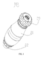
FIG. 1 is a perspective view of a battery assembly for an electronic cigarette according to a first embodiment. -
FIG. 2 is an exploded perspective view of the battery assembly ofFIG. 1 . -
FIG. 3 is an exploded perspective view of a rotatable electrode, a first holder, and a second holder. -
FIG. 4 is an inverted assembled perspective view of the rotatable electrode, the first and the second holders ofFIG. 3 , and a clip ring. -
FIG. 5 is a cross-sectional view of the battery assembly ofFIG. 1 in a first state. -
FIG. 6 is a cross-sectional view of the battery assembly ofFIG. 1 in a second state. -
FIG. 7 is a perspective view of a fixed electrode according to a second embodiment. -
FIG. 8 is a perspective view of an electronic cigarette according to a third embodiment. - It will be appreciated that for simplicity and clarity of illustration, where appropriate, reference numerals have been repeated among the different figures to indicate corresponding or analogous elements. In addition, numerous specific details are set forth in order to provide a thorough understanding of the embodiments described herein. However, it will be understood by those of ordinary skill in the art that the embodiments described herein can be practiced without these specific details. In other instances, methods, procedures and components have not been described in detail so as not to obscure the related relevant feature being described. Also, the description is not to be considered as limiting the scope of the embodiments described herein. The drawings are not necessarily to scale and the proportions of certain parts have been exaggerated to better illustrate details and features of the present disclosure.
- The disclosure is illustrated by way of example and not by way of limitation in the figures of the accompanying drawings in which like references indicate similar elements. It should be noted that references to "an" or "one" embodiment in this disclosure are not necessarily to the same embodiment, and such references mean at least one.
- Several definitions that apply throughout this disclosure will now be presented.
- The term "outside" refers to a region that is beyond the outermost confines of a physical object. The term "inside" indicates that at least a portion of a region is partially contained within a boundary formed by the object. The term "substantially" is defined to be essentially conforming to the particular dimension, shape or other word that substantially modifies, such that the component need not be exact. For example, substantially cylindrical means that the object resembles a cylinder, but can have one or more deviations from a true cylinder. The term "comprising," when utilized, means "including, but not necessarily limited to"; it specifically indicates open-ended inclusion or membership in the so-described combination, group, series and the like.
- Referring to
FIG. 1 andFIG. 2 , abattery assembly 100 for an electronic cigarette includes ahousing 21, abattery 20 arranged in thehousing 21, a first switch assembly. The first switch assembly includes afixed electrode 23, a rotatable electrode, an insulatedring 33, afirst holder 251, asecond holder 252, anengaging rod 26, anengaging ring 27, a threadedsleeve assembly 28, and arotatable sleeve 29. The rotatable electrode includes afirst electrode 241 and twosecond electrodes 242. - The
fixed electrode 23 includes an electrically insulatedarea 231, an electricallyconductive area 232, and acontact pin 233. In the present embodiment, theinsulated area 231 includes two through holes, each of which is larger than twosecond electrodes 242 in dimension; theconductive area 232 is a solid area. - The insulated
ring 33 defines a throughhole 333. Theinsulated area 231 and theconductive area 232 are positioned above the insulatedring 33, and thecontact pin 233 passes through the throughhole 333 to electrically connect with the battery. - Referring to
FIG. 3 , thefirst holder 251 includes a first central throughhole 27 and a plurality of locatingrods 250. Thesecond holder 252 includes a secondcentral hole 253, twoelectrode holes 254 and a plurality of locatingholes 260. Thefirst holder 251 further includes two spacedsidewalls 258 and twogaps 259. Thesecond holder 252 further includes two spacedsidewalls 255 and twogaps 256. - The
first electrode 241 goes through the first central throughhole 257, and is located in the second central throughhole 253. An end of thefirst electrode 241 is connected to an insulatedsheet 240 positioned in the second throughhole 253. The twosecond electrodes 242 are fixed at two ends of a conductiveelastic element 243, and received in the twoelectrode holes 254. The twosecond electrodes 242 protrude from the twoelectrode holes 254. The conductiveelastic element 243 is connected to thefirst electrode 241, and the twosecond electrodes 242 are electrically connected with thefirst electrode 241 via the conductiveelastic element 243. The locatingrods 250 insert into the locatingholes 260 in one-to-one relationship, so that thefirst holder 251 is positioned above thesecond holder 252, and presses the conductiveelastic element 243. Thefirst holder 251 is assembled with thesecond holder 252 in such a manner that the twosidewalls 258 are corresponding to the twogaps 256, and the twosidewalls 255 are corresponding to the twogaps 259. - Further, the
second holder 252 defines two locatingslots 262 radially extending to a side surface thereof. Twoelastic elements 261 are engaged in the two locatingslots 262. Twoengaging rods 26 hold against the twoelastic elements 261, and protrude from the side surface of thesecond holder 252. - Also referring to
FIG. 4 , aclip ring 27 is provided on an external wall of thesecond holder 252. Theclip ring 27 defines fourengaging slots 271. Theclip ring 27 is fixed at one end of thehousing 21. The twoengaging rods 26 are coupled with the twoelastic elements 261, and thus are movable along the locatingslots 262 so as to insert into the engagingslots 271 or disengage from the engagingslots 271. - In the present embodiment, the threaded
sleeve assembly 28 includes an external screw sleeve and an internal screw sleeve, and an end of the external screw sleeve is fixedly coupled with thefirst holder 251. The threadedsleeve assembly 28 is accommodated in aninternal space 291 of therotatable sleeve 29. An internal wall of therotatable sleeve 29 is fixedly engaged with an external wall of the threadedsleeve assembly 28 so that therotatable sleeve 29 drives the threadedsleeve assembly 28 to rotate when therotatable sleeve 29 is rotated. - Referring to
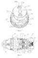
FIGS. 5-6 , when therotatable sleeve 29 is rotated, therotatable sleeve 29 drives the threadedsleeve assembly 28 to rotate, the threadedsleeve assembly 28 drives thefirst holder 251, thesecond holder 252, thefirst electrode 241, thesecond electrode 242, the engagingrods 26 to rotate. When the two engagingrods 26 insert in the twoengaging slots 271, the twosecond electrodes 242 are rotated to a first position (as seen inFIG. 5 ), where the twosecond electrodes 242 are in contact with theconductive area 232 of the fixedelectrode 23. In this position, the rotatable electrode is electrically connected to the fixedelectrode 23, and the first switch assembly is turned on. When therotatable sleeve 29 is continued to rotate, the two engagingrods 26 insert in the other twoengaging slots 271, the twosecond electrodes 242 are rotated to a second position (as seen inFIG. 6 ), where the twosecond electrodes 242 are located in theinsulated areas 231 of the fixedelectrode 23. In this position, the rotatable electrode is disconnected from the fixedelectrode 23, and the first switch assembly is turned off. - In the present embodiment, four
engaging slots 271 of the engagingring 27 are distributed along two diameters of the engagingring 27. Accordingly, the state of the first switch assembly is changed when therotatable sleeve 29 is rotated every 90 degrees. Thefirst electrode 241 is an elastic pin electrode, which includes afixed part 246, amovable part 245, and anelastic component 247 arranged between thefixed part 246 and themovable part 245. Themovable part 245 is movable along an axial direction thereof upon an external force. Accordingly, a length of thefirst electrode 241 can be adjusted. - It is to be understood that the total number of the engaging
rods 26 is not limited to two. For example, the total number of the engagingrods 26 may be only one, and the engaging rod may extend through a locating slot. The total number of the engaging slots is not limited to four. In addition, thefirst holder 251 and thesecond holder 252 may be integrally formed. Before molding, the conductiveelastic element 243 and theelastic elements 26 are embedded, and thesecond electrode 242 and the engagingrods 26 are respectively connected to the conductiveelastic element 243 and theelastic elements 26. - In other embodiments, the total number of the second electrodes may be only one, and the
second electrode 242 and thefirst electrode 241 may be integrally formed. - The electronic cigarette is turned on or off by rotating the first switch assembly, preventing the electronic cigarette from turning on when pressed by mistake. In the present embodiment, the battery assembly further includes a
push switch 22 arranged at an end of thehousing 21, and the first switch assembly serves as a safety switch or a locking switch. Thepush switch 22, as a second switch assembly, includes an internal elastic member. After the first switch assembly is turned on, the second switch further controls the battery assembly to turn on or off. When the second switch is pressed, the battery assembly is turned on; when the second switch is not pressed, the second switch restores to its natural state, and the battery assembly is turned off. - Referring to
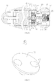
FIG. 7 , a fixedelectrode 43 according to a second embodiment is shown. The fixedelectrode 43 includes aninsulated area 431 made of insulated material and aconductive area 432 made of conductive material. It is noteworthy that positions of theinsulated area 431 and theconductive area 432 may be interchanged. - Referring to
FIG. 8 , anelectronic cigarette 200 includes the above-mentionedbattery assembly 100 and anatomizer 300. Thebattery assembly 100 is configured (i.e., structured and arranged) for powering theatomizer 300. Theatomizer 300 inserts into thebattery assembly 100, and is threadedly coupled to the threaded sleeve assembly of thebattery assembly 100. Theatomizer 300 includes an electrode (not shown) for connecting with thefirst electrode 241. Because the length of thefirst electrode 241 can be adjusted along the axial direction, thebattery assembly 100 fits theatomizer 300 with the electrode of different depths. After thebattery assembly 100 is connected with theatomizer 300, the first switch assembly can be switched to the on or off state by rotating therotatable sleeve 29. When the first switch assembly is turned on, a user of theelectronic cigarette 200 can press thesecond switch assembly 22 to smoke. When the user does not smoke, the first switch assembly is turned off, and theelectronic cigarette 200 will not work even if thesecond switch assembly 22 were pressed by mistake. - It is to be understood that the
atomizer 300 and thebattery assembly 100 may be integrally formed. - It is understood that the above-described embodiments are intended to illustrate rather than limit the disclosure. Variations may be made to the embodiments and methods without departing from the spirit of the disclosure. Accordingly, it is appropriate that the appended claims be construed broadly and in a manner consistent with the scope of the disclosure.
Claims (11)
- A battery assembly for an electronic cigarette, comprising:a housing;a battery received in the housing; anda first switch assembly connected to the battery, the first switch assembly comprising:a fixed electrode connected to the battery, the fixed electrode having a conductive area and an insulated area; anda rotatable electrode being rotatable between a first position and a second position, wherein in the first position, the rotatable electrode is in contact with the conductive area, thus connecting to the fixed electrode, and the first switch assembly is turned on; in the second position, the rotatable electrode is positioned in the insulated area, thus disconnecting from the fixed electrode, and the first switch assembly is turned off.
- The battery assembly of claim 1, further comprising a second switch assembly on the shell, wherein the second switch assembly is connected to the battery, and is configured for turning on or off the battery assembly after the first switch assembly is turned on.
- The battery assembly of claim 1, wherein the first switch assembly further comprises an insulated ring, the fixed electrode is arranged on the insulated ring, and passes through the insulated ring to connect to the battery.
- The battery assembly of claim 1, wherein the rotatable electrode comprises a first electrode, two second electrodes, and a first conductive elastic element, the first electrode is insulated from the fixed electrode, and the two second electrodes are connected to the first electrode via the first conductive elastic element.
- The battery assembly of claim 4, wherein the first electrode comprises a fixed part, a movable part, and a second conductive elastic element arranged between the fixed part and the movable part, the fixed part is connected with the first conductive elastic element, and the movable part is movable along an axial direction thereof upon a force exerted by the second conductive elastic element.
- The battery assembly of claim 4, wherein the first switch assembly further comprises a holder for supporting the first electrode and the two second electrodes, and the holder drives the first and the second electrodes to rotate relative to the fixed electrode.
- The battery assembly of claim 6, wherein the holder comprises a first holder and a second holder, the first holder comprises a first central through hole and a plurality of a plurality of locating rods, the second holder defines a second central hole, two electrode holes, and a plurality of locating holes, the first electrode passes through the first central through hole, and is located in the second central through hole, the two second electrodes are received in the two electrode holes, and protrude from the two electrode holes, the first conductive elastic element is clamped between the first and the second holders, and each locating rod inserts into a respective locating hole.
- The battery assembly of claim 7, wherein the first switch assembly further includes a clip ring, an engaging rod, and an elastic element the clip ring defines a plurality of engaging slots, the second holder defines a locating slot, an elastic element received in the locating slot, the engaging rod is held against the elastic element, and protrudes from the locating slot, and the engaging rod couples with different engaging slots when the second holder is in the first and the second positions.
- The battery assembly of claim 6, wherein the first switch assembly further includes a threaded sleeve assembly, the threaded sleeve assembly is fixedly connected with the first electrode and the holder, and the threaded sleeve assembly is configured for driving the first electrode, the holder, and the two second electrodes to rotate.
- The battery assembly of claim 9, wherein the first switch assembly further comprises a rotatable sleeve fixedly connected to the threaded sleeve assembly, and the rotatable sleeve is adapted for driving the threaded sleeve assembly.
- An electronic cigarette comprising:an atomizer; anda battery assembly according to any of claims 1-10, the battery assembly being configured for powering the atomizer.
Applications Claiming Priority (1)
| Application Number | Priority Date | Filing Date | Title |
|---|---|---|---|
| CN201420021294.1U CN203762295U (en) | 2014-01-14 | 2014-01-14 | Battery pack used for electronic cigarette and electronic cigarette |
Publications (2)
| Publication Number | Publication Date |
|---|---|
| EP2894651A1 true EP2894651A1 (en) | 2015-07-15 |
| EP2894651B1 EP2894651B1 (en) | 2017-06-28 |
Family
ID=51279562
Family Applications (1)
| Application Number | Title | Priority Date | Filing Date |
|---|---|---|---|
| EP15150718.3A Active EP2894651B1 (en) | 2014-01-14 | 2015-01-11 | Battery assembly and electronic cigarette having same |
Country Status (3)
| Country | Link |
|---|---|
| US (1) | US9894933B2 (en) |
| EP (1) | EP2894651B1 (en) |
| CN (1) | CN203762295U (en) |
Families Citing this family (37)
| Publication number | Priority date | Publication date | Assignee | Title |
|---|---|---|---|---|
| US10244793B2 (en) | 2005-07-19 | 2019-04-02 | Juul Labs, Inc. | Devices for vaporization of a substance |
| US10279934B2 (en) | 2013-03-15 | 2019-05-07 | Juul Labs, Inc. | Fillable vaporizer cartridge and method of filling |
| USD780990S1 (en) * | 2013-08-16 | 2017-03-07 | Huizhou Kimree Technology Co., Ltd. Shenzhen Branch | Electronic cigarette |
| US10039321B2 (en) | 2013-11-12 | 2018-08-07 | Vmr Products Llc | Vaporizer |
| US10076139B2 (en) | 2013-12-23 | 2018-09-18 | Juul Labs, Inc. | Vaporizer apparatus |
| TWM476481U (en) * | 2013-12-23 | 2014-04-21 | Qie Co Ltd | Electric cigarette body and switch assembly thereof |
| USD842536S1 (en) | 2016-07-28 | 2019-03-05 | Juul Labs, Inc. | Vaporizer cartridge |
| US10058129B2 (en) | 2013-12-23 | 2018-08-28 | Juul Labs, Inc. | Vaporization device systems and methods |
| US20160366947A1 (en) | 2013-12-23 | 2016-12-22 | James Monsees | Vaporizer apparatus |
| USD825102S1 (en) | 2016-07-28 | 2018-08-07 | Juul Labs, Inc. | Vaporizer device with cartridge |
| KR102721939B1 (en) | 2013-12-23 | 2024-10-25 | 쥴 랩스, 인크. | Vaporization device systems and methods |
| US10159282B2 (en) | 2013-12-23 | 2018-12-25 | Juul Labs, Inc. | Cartridge for use with a vaporizer device |
| JP1518257S (en) * | 2014-02-24 | 2015-02-23 | ||
| USD765307S1 (en) * | 2014-02-25 | 2016-08-30 | Qiuming Liu | Electronic cigarette |
| JP1518245S (en) * | 2014-02-25 | 2015-02-23 | ||
| USD765309S1 (en) * | 2014-02-25 | 2016-08-30 | Qiuming Liu | Electronic cigarette |
| USD758647S1 (en) * | 2014-02-25 | 2016-06-07 | Kimree Hi-Tech | Electronic cigarette |
| USD759297S1 (en) * | 2014-02-25 | 2016-06-14 | Kimree Hi-Tech Inc. | Electronic cigarette |
| JP1518255S (en) * | 2014-02-25 | 2015-02-23 | ||
| KR20250012730A (en) | 2014-12-05 | 2025-01-24 | 쥴 랩스, 인크. | Calibrated dose control |
| CN104824847B (en) * | 2015-03-10 | 2018-07-10 | 深圳麦克韦尔股份有限公司 | Electronic cigarette |
| CN104824848B (en) * | 2015-03-10 | 2018-04-03 | 深圳麦克韦尔股份有限公司 | Electronic cigarette |
| FR3034962B1 (en) * | 2015-04-14 | 2019-06-14 | Thierry CAI | DEVICE FOR ASSEMBLING A BATTERY ELEMENT WITH THE USE TIP OF AN ELECTRONIC CIGARETTE TO WHICH IT IS ASSOCIATED |
| CN105394815B (en) * | 2015-11-23 | 2018-08-07 | 深圳瀚星翔科技有限公司 | Electronic smoke atomizer |
| MX377347B (en) | 2016-02-11 | 2025-03-07 | Juul Labs Inc | Fillable vaporizer cartridge and method of filling |
| MX388616B (en) | 2016-02-11 | 2025-03-20 | Juul Labs Inc | SECURE FITTING CARTRIDGES FOR VAPORIZING DEVICES |
| US10405582B2 (en) | 2016-03-10 | 2019-09-10 | Pax Labs, Inc. | Vaporization device with lip sensing |
| USD849996S1 (en) | 2016-06-16 | 2019-05-28 | Pax Labs, Inc. | Vaporizer cartridge |
| USD836541S1 (en) | 2016-06-23 | 2018-12-25 | Pax Labs, Inc. | Charging device |
| USD848057S1 (en) | 2016-06-23 | 2019-05-07 | Pax Labs, Inc. | Lid for a vaporizer |
| USD851830S1 (en) | 2016-06-23 | 2019-06-18 | Pax Labs, Inc. | Combined vaporizer tamp and pick tool |
| CN107080293B (en) * | 2017-06-13 | 2023-09-19 | 云南中烟工业有限责任公司 | A safe and reliable electronic cigarette |
| CN207282560U (en) * | 2017-08-30 | 2018-04-27 | 常州市派腾电子技术服务有限公司 | Battery component and its electronic cigarette |
| USD887632S1 (en) | 2017-09-14 | 2020-06-16 | Pax Labs, Inc. | Vaporizer cartridge |
| US10729175B2 (en) * | 2018-03-02 | 2020-08-04 | Esquire Properties Trading Inc. | Vaporizer electrical system having a moving electrode with a combined electrical and airflow regulation function |
| CN108143011A (en) * | 2018-03-05 | 2018-06-12 | 深圳市金卓恒电子科技有限公司 | Electronic cigarette battery bar and electronic cigarette |
| CN116649636B (en) * | 2023-06-28 | 2026-04-10 | 深圳市吉迩科技有限公司 | An electronic atomizing device |
Citations (3)
| Publication number | Priority date | Publication date | Assignee | Title |
|---|---|---|---|---|
| EP0430566A2 (en) * | 1989-12-01 | 1991-06-05 | Philip Morris Products Inc. | Flavor delivering article |
| US7705261B1 (en) * | 2009-02-09 | 2010-04-27 | Chien-Hung Chen | Pull-rotary filter switch |
| CN103054196A (en) * | 2013-01-10 | 2013-04-24 | 深圳市合元科技有限公司 | Electronic cigarette atomizer |
Family Cites Families (9)
| Publication number | Priority date | Publication date | Assignee | Title |
|---|---|---|---|---|
| US9854839B2 (en) * | 2012-01-31 | 2018-01-02 | Altria Client Services Llc | Electronic vaping device and method |
| KR101316347B1 (en) * | 2012-04-03 | 2013-10-08 | 박선순 | Electronic cigarette |
| WO2014008623A1 (en) * | 2012-07-09 | 2014-01-16 | Liu Qiuming | Electronic cigarette |
| CN103349362A (en) * | 2013-06-14 | 2013-10-16 | 深圳市合元科技有限公司 | Battery pack for electronic cigarette and electronic cigarette |
| TWM476481U (en) * | 2013-12-23 | 2014-04-21 | Qie Co Ltd | Electric cigarette body and switch assembly thereof |
| US9861133B2 (en) * | 2013-12-31 | 2018-01-09 | Shenzhen First Union Technology Co., Ltd. | Electronic cigarette |
| CN203913391U (en) * | 2014-05-15 | 2014-11-05 | 深圳市合元科技有限公司 | Electronic cigarette and electric supply installation |
| WO2016074231A1 (en) * | 2014-11-14 | 2016-05-19 | 深圳麦克韦尔股份有限公司 | Electronic cigarette |
| CN204444245U (en) * | 2015-01-05 | 2015-07-08 | 深圳市合元科技有限公司 | Removable atomization unit and the atomizer and the electronic cigarette that comprise this atomization unit |
-
2014
- 2014-01-14 CN CN201420021294.1U patent/CN203762295U/en not_active Expired - Lifetime
-
2015
- 2015-01-11 EP EP15150718.3A patent/EP2894651B1/en active Active
- 2015-01-14 US US14/597,178 patent/US9894933B2/en active Active
Patent Citations (3)
| Publication number | Priority date | Publication date | Assignee | Title |
|---|---|---|---|---|
| EP0430566A2 (en) * | 1989-12-01 | 1991-06-05 | Philip Morris Products Inc. | Flavor delivering article |
| US7705261B1 (en) * | 2009-02-09 | 2010-04-27 | Chien-Hung Chen | Pull-rotary filter switch |
| CN103054196A (en) * | 2013-01-10 | 2013-04-24 | 深圳市合元科技有限公司 | Electronic cigarette atomizer |
Also Published As
| Publication number | Publication date |
|---|---|
| EP2894651B1 (en) | 2017-06-28 |
| CN203762295U (en) | 2014-08-13 |
| US9894933B2 (en) | 2018-02-20 |
| US20150196062A1 (en) | 2015-07-16 |
Similar Documents
| Publication | Publication Date | Title |
|---|---|---|
| EP2894651B1 (en) | Battery assembly and electronic cigarette having same | |
| EP3174367B1 (en) | Heating assembly and cigarette heating device having same | |
| US10045563B2 (en) | Atomizer, power supply, and electronic cigarette having same | |
| US9474305B2 (en) | Electronic cigarette | |
| EP3216358A1 (en) | Connector, power supply, atomizer and electronic cigarette having same | |
| EP3039976B1 (en) | Replaceable atomizing unit, atomizer and electronic cigarette having same | |
| US9974332B2 (en) | Electronic cigarette charging dock, electronic cigarette case, and method for use thereof | |
| JP2015222748A5 (en) | ||
| CN104953370A (en) | Power supply equipment interface device capable of achieving electrical connection automatically | |
| CN104868305A (en) | Power supply interface device of power supply equipment with roller grooves | |
| CN104916988A (en) | Power supply equipment power supply interface device with elastic sheets | |
| CN104916991A (en) | Power supply equipment power supply interface device with slide chutes | |
| CN104953390A (en) | Lockable power supply equipment interface device | |
| US7182615B1 (en) | Electric socket having means to lock the blades of inserted electric plug | |
| JP6086822B2 (en) | Deburring tool for deburring the bore edge | |
| RU2017139253A (en) | DEVICE FOR ASSEMBLY OF ACCUMULATOR ELEMENT WITH CONSUMPTION CARTRIDGE OF ELECTRONIC CIGARETTE WITH WHICH IT IS CONNECTED | |
| CN104916986A (en) | Power supply equipment interface device with electrical connection driven by screw rod | |
| CN104916987A (en) | Speed-adjustable power supply equipment power supply interface device | |
| WO2007023790A8 (en) | Spark plug | |
| CN104916990A (en) | Power supply equipment power supply interface device | |
| KR20140058235A (en) | Welder for power cable connector | |
| KR101338129B1 (en) | Terminal plate connection apparatus for power distribution | |
| EP2139073B1 (en) | Electrical connection bridge and block | |
| US9716329B1 (en) | Rotation element and safety plug with the rotation element | |
| CN213696820U (en) | Endoscope steel wire stop device |
Legal Events
| Date | Code | Title | Description |
|---|---|---|---|
| PUAI | Public reference made under article 153(3) epc to a published international application that has entered the european phase |
Free format text: ORIGINAL CODE: 0009012 |
|
| 17P | Request for examination filed |
Effective date: 20150121 |
|
| AK | Designated contracting states |
Kind code of ref document: A1 Designated state(s): AL AT BE BG CH CY CZ DE DK EE ES FI FR GB GR HR HU IE IS IT LI LT LU LV MC MK MT NL NO PL PT RO RS SE SI SK SM TR |
|
| AX | Request for extension of the european patent |
Extension state: BA ME |
|
| GRAP | Despatch of communication of intention to grant a patent |
Free format text: ORIGINAL CODE: EPIDOSNIGR1 |
|
| RIC1 | Information provided on ipc code assigned before grant |
Ipc: H01H 19/11 20060101ALN20161219BHEP Ipc: H01H 19/36 20060101AFI20161219BHEP Ipc: A24F 47/00 20060101ALI20161219BHEP Ipc: H01H 3/20 20060101ALI20161219BHEP Ipc: H01M 2/10 20060101ALI20161219BHEP |
|
| INTG | Intention to grant announced |
Effective date: 20170110 |
|
| GRAS | Grant fee paid |
Free format text: ORIGINAL CODE: EPIDOSNIGR3 |
|
| GRAA | (expected) grant |
Free format text: ORIGINAL CODE: 0009210 |
|
| AK | Designated contracting states |
Kind code of ref document: B1 Designated state(s): AL AT BE BG CH CY CZ DE DK EE ES FI FR GB GR HR HU IE IS IT LI LT LU LV MC MK MT NL NO PL PT RO RS SE SI SK SM TR |
|
| REG | Reference to a national code |
Ref country code: GB Ref legal event code: FG4D |
|
| REG | Reference to a national code |
Ref country code: CH Ref legal event code: EP |
|
| REG | Reference to a national code |
Ref country code: AT Ref legal event code: REF Ref document number: 905526 Country of ref document: AT Kind code of ref document: T Effective date: 20170715 |
|
| REG | Reference to a national code |
Ref country code: IE Ref legal event code: FG4D |
|
| REG | Reference to a national code |
Ref country code: DE Ref legal event code: R096 Ref document number: 602015003247 Country of ref document: DE |
|
| REG | Reference to a national code |
Ref country code: NL Ref legal event code: FP |
|
| PG25 | Lapsed in a contracting state [announced via postgrant information from national office to epo] |
Ref country code: HR Free format text: LAPSE BECAUSE OF FAILURE TO SUBMIT A TRANSLATION OF THE DESCRIPTION OR TO PAY THE FEE WITHIN THE PRESCRIBED TIME-LIMIT Effective date: 20170628 Ref country code: GR Free format text: LAPSE BECAUSE OF FAILURE TO SUBMIT A TRANSLATION OF THE DESCRIPTION OR TO PAY THE FEE WITHIN THE PRESCRIBED TIME-LIMIT Effective date: 20170929 Ref country code: NO Free format text: LAPSE BECAUSE OF FAILURE TO SUBMIT A TRANSLATION OF THE DESCRIPTION OR TO PAY THE FEE WITHIN THE PRESCRIBED TIME-LIMIT Effective date: 20170928 Ref country code: LT Free format text: LAPSE BECAUSE OF FAILURE TO SUBMIT A TRANSLATION OF THE DESCRIPTION OR TO PAY THE FEE WITHIN THE PRESCRIBED TIME-LIMIT Effective date: 20170628 Ref country code: FI Free format text: LAPSE BECAUSE OF FAILURE TO SUBMIT A TRANSLATION OF THE DESCRIPTION OR TO PAY THE FEE WITHIN THE PRESCRIBED TIME-LIMIT Effective date: 20170628 |
|
| REG | Reference to a national code |
Ref country code: LT Ref legal event code: MG4D |
|
| REG | Reference to a national code |
Ref country code: AT Ref legal event code: MK05 Ref document number: 905526 Country of ref document: AT Kind code of ref document: T Effective date: 20170628 |
|
| PG25 | Lapsed in a contracting state [announced via postgrant information from national office to epo] |
Ref country code: BG Free format text: LAPSE BECAUSE OF FAILURE TO SUBMIT A TRANSLATION OF THE DESCRIPTION OR TO PAY THE FEE WITHIN THE PRESCRIBED TIME-LIMIT Effective date: 20170928 Ref country code: LV Free format text: LAPSE BECAUSE OF FAILURE TO SUBMIT A TRANSLATION OF THE DESCRIPTION OR TO PAY THE FEE WITHIN THE PRESCRIBED TIME-LIMIT Effective date: 20170628 Ref country code: RS Free format text: LAPSE BECAUSE OF FAILURE TO SUBMIT A TRANSLATION OF THE DESCRIPTION OR TO PAY THE FEE WITHIN THE PRESCRIBED TIME-LIMIT Effective date: 20170628 Ref country code: SE Free format text: LAPSE BECAUSE OF FAILURE TO SUBMIT A TRANSLATION OF THE DESCRIPTION OR TO PAY THE FEE WITHIN THE PRESCRIBED TIME-LIMIT Effective date: 20170628 |
|
| PG25 | Lapsed in a contracting state [announced via postgrant information from national office to epo] |
Ref country code: EE Free format text: LAPSE BECAUSE OF FAILURE TO SUBMIT A TRANSLATION OF THE DESCRIPTION OR TO PAY THE FEE WITHIN THE PRESCRIBED TIME-LIMIT Effective date: 20170628 Ref country code: SK Free format text: LAPSE BECAUSE OF FAILURE TO SUBMIT A TRANSLATION OF THE DESCRIPTION OR TO PAY THE FEE WITHIN THE PRESCRIBED TIME-LIMIT Effective date: 20170628 Ref country code: CZ Free format text: LAPSE BECAUSE OF FAILURE TO SUBMIT A TRANSLATION OF THE DESCRIPTION OR TO PAY THE FEE WITHIN THE PRESCRIBED TIME-LIMIT Effective date: 20170628 Ref country code: AT Free format text: LAPSE BECAUSE OF FAILURE TO SUBMIT A TRANSLATION OF THE DESCRIPTION OR TO PAY THE FEE WITHIN THE PRESCRIBED TIME-LIMIT Effective date: 20170628 Ref country code: RO Free format text: LAPSE BECAUSE OF FAILURE TO SUBMIT A TRANSLATION OF THE DESCRIPTION OR TO PAY THE FEE WITHIN THE PRESCRIBED TIME-LIMIT Effective date: 20170628 |
|
| REG | Reference to a national code |
Ref country code: FR Ref legal event code: PLFP Year of fee payment: 4 |
|
| PG25 | Lapsed in a contracting state [announced via postgrant information from national office to epo] |
Ref country code: ES Free format text: LAPSE BECAUSE OF FAILURE TO SUBMIT A TRANSLATION OF THE DESCRIPTION OR TO PAY THE FEE WITHIN THE PRESCRIBED TIME-LIMIT Effective date: 20170628 Ref country code: IS Free format text: LAPSE BECAUSE OF FAILURE TO SUBMIT A TRANSLATION OF THE DESCRIPTION OR TO PAY THE FEE WITHIN THE PRESCRIBED TIME-LIMIT Effective date: 20171028 Ref country code: SM Free format text: LAPSE BECAUSE OF FAILURE TO SUBMIT A TRANSLATION OF THE DESCRIPTION OR TO PAY THE FEE WITHIN THE PRESCRIBED TIME-LIMIT Effective date: 20170628 Ref country code: PL Free format text: LAPSE BECAUSE OF FAILURE TO SUBMIT A TRANSLATION OF THE DESCRIPTION OR TO PAY THE FEE WITHIN THE PRESCRIBED TIME-LIMIT Effective date: 20170628 |
|
| REG | Reference to a national code |
Ref country code: DE Ref legal event code: R097 Ref document number: 602015003247 Country of ref document: DE |
|
| PG25 | Lapsed in a contracting state [announced via postgrant information from national office to epo] |
Ref country code: DK Free format text: LAPSE BECAUSE OF FAILURE TO SUBMIT A TRANSLATION OF THE DESCRIPTION OR TO PAY THE FEE WITHIN THE PRESCRIBED TIME-LIMIT Effective date: 20170628 |
|
| PLBE | No opposition filed within time limit |
Free format text: ORIGINAL CODE: 0009261 |
|
| STAA | Information on the status of an ep patent application or granted ep patent |
Free format text: STATUS: NO OPPOSITION FILED WITHIN TIME LIMIT |
|
| 26N | No opposition filed |
Effective date: 20180329 |
|
| PG25 | Lapsed in a contracting state [announced via postgrant information from national office to epo] |
Ref country code: SI Free format text: LAPSE BECAUSE OF FAILURE TO SUBMIT A TRANSLATION OF THE DESCRIPTION OR TO PAY THE FEE WITHIN THE PRESCRIBED TIME-LIMIT Effective date: 20170628 |
|
| PG25 | Lapsed in a contracting state [announced via postgrant information from national office to epo] |
Ref country code: LU Free format text: LAPSE BECAUSE OF NON-PAYMENT OF DUE FEES Effective date: 20180111 |
|
| REG | Reference to a national code |
Ref country code: BE Ref legal event code: MM Effective date: 20180131 |
|
| PG25 | Lapsed in a contracting state [announced via postgrant information from national office to epo] |
Ref country code: BE Free format text: LAPSE BECAUSE OF NON-PAYMENT OF DUE FEES Effective date: 20180131 |
|
| PG25 | Lapsed in a contracting state [announced via postgrant information from national office to epo] |
Ref country code: MC Free format text: LAPSE BECAUSE OF FAILURE TO SUBMIT A TRANSLATION OF THE DESCRIPTION OR TO PAY THE FEE WITHIN THE PRESCRIBED TIME-LIMIT Effective date: 20170628 |
|
| PG25 | Lapsed in a contracting state [announced via postgrant information from national office to epo] |
Ref country code: MT Free format text: LAPSE BECAUSE OF NON-PAYMENT OF DUE FEES Effective date: 20180111 |
|
| PG25 | Lapsed in a contracting state [announced via postgrant information from national office to epo] |
Ref country code: TR Free format text: LAPSE BECAUSE OF FAILURE TO SUBMIT A TRANSLATION OF THE DESCRIPTION OR TO PAY THE FEE WITHIN THE PRESCRIBED TIME-LIMIT Effective date: 20170628 |
|
| PG25 | Lapsed in a contracting state [announced via postgrant information from national office to epo] |
Ref country code: PT Free format text: LAPSE BECAUSE OF FAILURE TO SUBMIT A TRANSLATION OF THE DESCRIPTION OR TO PAY THE FEE WITHIN THE PRESCRIBED TIME-LIMIT Effective date: 20170628 |
|
| PG25 | Lapsed in a contracting state [announced via postgrant information from national office to epo] |
Ref country code: HU Free format text: LAPSE BECAUSE OF FAILURE TO SUBMIT A TRANSLATION OF THE DESCRIPTION OR TO PAY THE FEE WITHIN THE PRESCRIBED TIME-LIMIT; INVALID AB INITIO Effective date: 20150111 Ref country code: CY Free format text: LAPSE BECAUSE OF FAILURE TO SUBMIT A TRANSLATION OF THE DESCRIPTION OR TO PAY THE FEE WITHIN THE PRESCRIBED TIME-LIMIT Effective date: 20170628 Ref country code: MK Free format text: LAPSE BECAUSE OF NON-PAYMENT OF DUE FEES Effective date: 20170628 |
|
| PG25 | Lapsed in a contracting state [announced via postgrant information from national office to epo] |
Ref country code: AL Free format text: LAPSE BECAUSE OF FAILURE TO SUBMIT A TRANSLATION OF THE DESCRIPTION OR TO PAY THE FEE WITHIN THE PRESCRIBED TIME-LIMIT Effective date: 20170628 |
|
| P01 | Opt-out of the competence of the unified patent court (upc) registered |
Free format text: CASE NUMBER: APP_4915/2025 Effective date: 20250129 |
|
| PGFP | Annual fee paid to national office [announced via postgrant information from national office to epo] |
Ref country code: NL Payment date: 20251230 Year of fee payment: 12 |
|
| PGFP | Annual fee paid to national office [announced via postgrant information from national office to epo] |
Ref country code: IE Payment date: 20251223 Year of fee payment: 12 |
|
| REG | Reference to a national code |
Ref country code: CH Ref legal event code: U11 Free format text: ST27 STATUS EVENT CODE: U-0-0-U10-U11 (AS PROVIDED BY THE NATIONAL OFFICE) Effective date: 20260201 |
|
| PGFP | Annual fee paid to national office [announced via postgrant information from national office to epo] |
Ref country code: GB Payment date: 20260127 Year of fee payment: 12 |
|
| PGFP | Annual fee paid to national office [announced via postgrant information from national office to epo] |
Ref country code: DE Payment date: 20260114 Year of fee payment: 12 |
|
| PGFP | Annual fee paid to national office [announced via postgrant information from national office to epo] |
Ref country code: IT Payment date: 20260108 Year of fee payment: 12 |
|
| PGFP | Annual fee paid to national office [announced via postgrant information from national office to epo] |
Ref country code: FR Payment date: 20260128 Year of fee payment: 12 |
|
| PGFP | Annual fee paid to national office [announced via postgrant information from national office to epo] |
Ref country code: CH Payment date: 20260201 Year of fee payment: 12 |