EP2894580A1 - Assessment of assemblies - Google Patents
Assessment of assemblies Download PDFInfo
- Publication number
- EP2894580A1 EP2894580A1 EP14275004.1A EP14275004A EP2894580A1 EP 2894580 A1 EP2894580 A1 EP 2894580A1 EP 14275004 A EP14275004 A EP 14275004A EP 2894580 A1 EP2894580 A1 EP 2894580A1
- Authority
- EP
- European Patent Office
- Prior art keywords
- assembly
- joint assembly
- digital model
- electrical circuit
- assessment
- Prior art date
- Legal status (The legal status is an assumption and is not a legal conclusion. Google has not performed a legal analysis and makes no representation as to the accuracy of the status listed.)
- Ceased
Links
Images


Classifications
-
- G—PHYSICS
- G06—COMPUTING OR CALCULATING; COUNTING
- G06F—ELECTRIC DIGITAL DATA PROCESSING
- G06F30/00—Computer-aided design [CAD]
- G06F30/10—Geometric CAD
- G06F30/15—Vehicle, aircraft or watercraft design
-
- G—PHYSICS
- G06—COMPUTING OR CALCULATING; COUNTING
- G06F—ELECTRIC DIGITAL DATA PROCESSING
- G06F30/00—Computer-aided design [CAD]
- G06F30/20—Design optimisation, verification or simulation
Definitions
- the present invention relates to the assessment of the effects of lightning strikes on assemblies.
- Effects on joint assemblies range from no effect at all, to sparking, degradation due to the overheating of non-metallic shim materials, degradation due to the overheating of metallic components, destruction of fasteners, or even explosive destruction of the joint assembly itself.
- the effects of a lightning strike on a joint assembly depend upon a number of factors including, but not limited to, the configuration of the component parts in the joint assembly.
- assessing the threat lightning poses to a joint assembly involves expensive and time consuming testing.
- Such testing typically requires manufacture of articles representative of the joint assembly under test, assessment of the lightning threat, and testing of the articles at a suitably equipped laboratory.
- the present invention provides a method of providing an assessment of the effects of a lightning strike on an assembly, the method comprising: acquiring values for a plurality of physical properties of the assembly; using the acquired values, generating a digital model of an electrical circuit representative of the assembly; applying, to the digital model, an input so as to simulate a predetermined current being applied to the electrical circuit, the predetermined current being a current generated by a lightning strike; determining an effect of the input on at least a portion of the digital model; and, using the determined effect, determining the assessment of the assembly.
- the digital model of the electrical circuit may comprise digital models of a plurality of electrical components selected from the group consisting of resistors, inductors, and capacitors.
- the electrical properties of the electrical components may be determined using the acquired physical properties of the assembly such that the electrical circuit is substantially electrically equivalent to the assembly.
- the method may further comprise determining the predetermined current.
- the predetermined current may be determined using a double exponential waveform having a magnitude and waveform that may be determined by assessing an overall structure of which the assembly is a part.
- the predetermined current may be determined by determining the number of parallel electrical paths that exist within an overall structure of which the assembly is a part from a lightning strike location to an exit location of the lightning current, and dividing a lightning current between those parallel paths (e.g. proportionally according to the respective resistances of the paths).
- the assembly may be a joint assembly comprising at least two components fixedly attached together.
- the two components may be fixedly attached together by means of fasteners passing at least partially through each of the at least two components and/or by means of a sealant.
- the joint assembly may be an aircraft structural joint assembly that couples together two component parts of an aircraft substructure or airframe.
- the step of acquiring values for a plurality of physical properties of the assembly may comprises providing at least part of the assembly, and measuring, using a measurement device, the at least part of the assembly so as to determine values for one or more of the physical properties.
- values for a plurality of physical properties of the assembly may be acquired from design data or manufacturer's specifications.
- the method may further comprise, using the assessment of the assembly, modifying the assembly, for example, to improve its lightning strike performance.
- At least one physical property of the assembly may be a physical property selected from the group of physical properties consisting of: a physical dimension of at least part of the assembly, a dielectric strength of at least part of the assembly, a resistance through at least part of the assembly, an inductance through at least part of the assembly, a capacitance of at least part of the assembly, a resistivity of at least part of the assembly, a permittivity of at least part of the assembly, a breakdown voltage of at least part of the assembly, and a material from which of at least part of the assembly is made.
- At least part of the assembly may be represented in the digital model by a plurality of nodes connected together in series and a plurality of nodes connected together in parallel.
- Each node may comprise a digital model of a resistor coupled (e.g. in series) to an inductor.
- the present invention provides a method of comparing two of more assemblies, the method comprising: for each assembly, determining an assessment of that assembly by performing, for that assembly, an assessment method according to the first aspect; and, using the determined assessments, comparing the assemblies.
- the present invention provides apparatus for providing an assessment of the effects of a lightning strike on an assembly, the apparatus comprising: means for acquiring values for a plurality of physical properties of the assembly; and one or more processors configured to: using the acquired values, generate a digital model of an electrical circuit representative of the assembly; apply, to the digital model, an input so as to simulate a predetermined current being applied to the electrical circuit, the predetermined current being a current generated by a lightning strike; determine an effect of the input on at least a portion of the digital model; and, using the determined effect, determine the assessment of the assembly.
- the present invention provides a program or plurality of programs arranged such that when executed by a computer system or one or more processors it/they cause the computer system or the one or more processors to operate in accordance with the method of any of the above aspects.
- the present invention provides a machine readable storage medium storing a program or at least one of the plurality of programs according to the preceding aspect.
- Figure 1 is a schematic illustration (not to scale) of a cross section of a first example joint assembly, hereinafter referred to as the "first joint assembly” and indicated in the Figures by the reference numeral 2, which will be used to illustrate an embodiment of a joint assembly analysis process.
- the first joint assembly 2 is onboard an aircraft.
- the first joint assembly 2 comprises a first layer of material 4 fixedly coupled to a second layer of material 6.
- the first layer of material 4 is part of an airframe or substructure of the aircraft and may be made of titanium.
- the second layer of material 6 is part of an airframe or substructure of the aircraft and may be made of titanium.
- a metallic shim 8 is disposed between the first layer 4 and second layer 6.
- the metallic shim 8 may be made of titanium.
- the first layer 4, the second layer 6, and the metallic shim 8 have been wet assembled together using a sealant 10.
- the sealant 10 is relatively non-conductive compared to the first layer 4, the second layer 6, and the metallic shim 8.
- the sealant 10 is disposed between the first layer 4 and the metallic shim 8, and between the metallic shim 8 and the second layer 6.
- each fastener 12 comprises a bolt 14, a shaft of which extends through the first layer 4, the second layer 6, and the metallic shim 8, from a bottom surface of the second layer 6, to a top surface of the first layer.
- Each fastener 12 further comprises a nut 16 which is attached to a respective bolt 14 at a top surface of the first layer 4, so as to secure that bolt 14 in place. The nuts 16 of the fasteners 12 may have been tightened on to the respective bolt 14 to a predetermined torque.
- the sealant 10 electrically isolates the first layer 4 from the shafts of the bolts 14. Also, the sealant 10 electrically isolates the second layer 4 from the shafts of the bolts 14. In some cases tightening of the fasteners 12 may causes some contact between the fasteners 12 and the first later 4, the shim 8 and/or the second layer 6.
- the first joint assembly 2 further comprises layers of a protective coating 18 disposed on the top surface of the first layer 4 and on the bottom surface of the second layer 6.
- the protective coating 18 may be a paint or other substance which is relative electrically non-conductive.
- the protective coating 18 may be a primer.
- the protective coating 18 on the top surface of the first layer 4 electrically isolates the first layer 4 from the fasteners 12.
- the protective coating 18 on the bottom surface of the second layer 6 electrically isolates the second layer 6 from the fasteners 12.
- FIG 2 is a schematic illustration (not to scale) of a cross section of a second example joint assembly, hereinafter referred to as the "second joint assembly" and indicated in the Figures by the reference numeral 20, which will be used to illustrate an embodiment of a joint assembly analysis process.
- the elements of the second joint assembly 20 are arranged in the same way as in the first joint assembly 2, as described in more detail above with reference to Figure 1 , except that, in the second joint assembly 20, the protective layer 18 does not electrically isolate the first layer 4 from the nut 16. In other words, in the second joint assembly 20, the first and second layers are each in electrical contact with the nut 16.
- Figure 3 is a process flow chart showing certain steps of an embodiment of a joint assembly analysis process which may be performed to assess the joint assemblies 2, 20. Assessments of the joint assemblies 2, 20 may be used to compare the joint assemblies to each other.
- a joint assembly 2, 20 is provided.
- step s4 various physical properties of the provided joint assembly 2, 20 are determined or acquired.
- Joint assembly properties may be determined from design data, manufacturer's specifications, or by taking measurements of the joint assembly 2, 20 as a whole, and/or the individual components that make up the provided joint assembly 2, 20.
- Step s6 of the process, at which the determined properties are used to create an electrical circuit equivalent to the joint assembly 2, 20, will be described in more detail later below after discussion of the joint assembly properties.
- Joint assembly properties that may be determined may include, but are not limited to, thicknesses of the layers of material in the joint assembly 2, 20, dielectric properties of the components of the joint assemblies 2, 20, the materials from which the components of the joint assembly 2, 20 are made, and the dimensions of the fasteners 12 of the joint assembly 2, 20.
- the DC resistance through a joint assembly 2, 20 may be as a result of small patches of (e.g. metallic) contact between the first layer 4 and the metallic shim 8 and between the metallic shim 8 and the second layer 6, where the inherent roughness of the surfaces of the layers 4, 6, 8 penetrate the sealant film 10 within a certain area.
- small patches of e.g. metallic
- these contacts between layers 4, 6, 8 are considered to be a set of n circles, each having diameter d.
- the circles are distributed across a circular contact area of diameter D.
- the circles represent contacts between surfaces of resistivity p.
- the resistance through a joint assembly 2, 20 is approximated as: R ⁇ ⁇ D + ⁇ nd
- nd may be calculated.
- first joint assembly 2 there is an electrical connection between the first and second layers 4, 6, in two series stages via the metallic shim 8. As mentioned earlier above, this electrical contact corresponds to a certain contact area.
- the second joint assembly 20 in addition to the electrical connection between the first and second layers 4, 6, in two series stages via the metallic shim 8, there is additionally electrical connection between the first layer 4 and the fasteners 12 via the contact between the top surface of the first layer 4 and the underside of the nut 16.
- a diameter of a circle representing this contact area between the fasteners 12 at the first layer 4 may be calculated as mentioned earlier above.
- each sealant layer 10 may be specified from, for example, manufacturing tolerances.
- the dielectric strength of the sealant 10 may be determined by measurement or from a manufacturer's specification. This parameter value may be expressed kV/mm. The permittivity of the sealant 10 is may also be determined.
- a breakdown voltage of the joint assembly 2, 20 may be calculated from the thickness and dielectric strength of the sealant 10.
- the cross sectional area of the shafts of the bolts 14, the lengths of the bolts 14 from bolt head to nut 16 contact surfaces, and any gaps in the joint assembly 2, 20 may be determined, for example from design data or by measuring.
- the thickness, dielectric strength and permittivity of the protective coating 18 may be acquired, for example, from a manufacturer's specification, or determined, for example, via experimentation.
- the inductance and resistance of a single contact point may be calculated using expressions for inductance and resistance analogous to those provided above.
- the nut 16 and first layer 4 form a capacitance which is defined by the gap between the metal surfaces, the surface area involved, and the dielectric properties of the protective coating 18.
- This capacitance can be calculated using an expression for capacitance analogous to that provided above.
- a breakdown voltage between the nut 16 and the first layer 4 may be calculated from the thickness and dielectric strength of the protective coating 18.
- an electrical circuit that is representative of, i.e. electrically equivalent to, the joint assembly 2, 20 is determined.
- the measured/determined dimensions of the components of the joint assembly 2, 20 may be used to estimate the inductances and capacitances within the electrical circuit.
- the electrical circuit has all relevant electrical characteristics of the joint assembly 2, 20 being assessed.
- the model of the electrical circuit is a digital model created by a user using a computer and any appropriate software package.
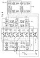
- Figure 4 is a schematic illustration (not to scale) showing an example electrical circuit 22 that is electrically equivalent to the first joint assembly 2.
- the electrical circuit 22 comprises a plurality of resistors, inductors and capacitors.
- the resistances of each of the resistors may be specified based on the joint properties determined earlier at step s4.
- the inductances of each of the inductors may be specified based on the joint properties determined earlier at step s4.
- the capacitances of each of the capacitors may be specified based on the joint properties determined earlier at step s4.
- the electrical circuit 22 further comprises an input 23 to which a simulated input current may be applied.
- the electrical circuit 22 comprises a plurality of lattices.
- Each lattice is a discretised representation of the joint materials, connected by inductances, resistances and capacitances.
- the electrical circuit is an advantageously compact representation of the first joint assembly 2 which includes all the features used in the joint analysis process.
- the lattice of the electrical circuit 22 that is representative of the first layer 4 is shown in Figure 4 inside a box marked with the reference numeral 4.
- each of the first and second layers of material 4, 6 are represented by a lattice of nodes, the nodes comprising a resistor coupled in series with an inductor.
- Each of the first and second layers 4, 6 comprise, in the x-direction, three of these nodes connected in parallel and two of these nodes connected in series.
- each of the first and second layers 4, 6 comprise, in the y-direction, two of these nodes connected in parallel and two of these nodes connected in series.
- the lattices representing the first and second layers 4, 6 are modelled to be connected via eight contact points representing contact between the two layers 4, 6 through the metallic shim 8 (shown in Figure 4 within the box labelled with the reference numeral 8), plus an additional contact point representing contact between the two layers 4, 6 via the fasteners 12 (shown in Figure 4 within the box labelled with the reference numeral 12). In other embodiments, there may be a different number of contact points.
- the impedances of the eight contact points representing contact between the two layers 4, 6 through the metallic shim 8 combine to that calculated in step s4 above.
- each resistance and inductance may be calculated by the scaling of the joint impedance by the number of nodes (i.e. by eight).
- each capacitance may be calculated by dividing the capacitance between the faces of the first layer 4 and the metallic shim 8 and the metallic shim 8 and the second layer 6, by the number of nodes (i.e. by eight). This tends to provide that the combined impedance is equal to the overall joint impedance as calculated in step s4 above.
- the embodiment may be easily varied to facilitate the investigation of different joint realisations, for example, to account for a single point contact rather than a distribution of contacts.
- a different number e.g. more than eight
- contact points are present between the first layer 4 and the second layer 6 via the shim 8 and sealant 10.
- the fasteners 12 are represented in the electrical circuit 22 by a combination of resistors, capacitors, and inductors (shown in Figure 4 within the box labelled with the reference numeral 12) that provide the resistances, inductances and capacitances of the fasteners 12 determined at step s4.
- the input 23 may be the lightning current scaled for double exponential use;
- Ix may be an X inductance per unit;
- Iy may be a Y inductance per unit;
- Cz may be a joint capacitance per point;
- Rc may be a joint resistance per point;
- Lc may be a joint inductance per point;
- Rf may be a fastener shank resistance;
- Lf may be a fastener shank inductance;
- Rs may be a shank contact resistance;
- Rn may be a head/nut contact resistance; and
- Cn may be a head/nut contact capacitance.
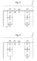
- Figure 5 is a schematic illustration (not to scale) showing an example configuration (hereinafter referred to as the "first configuration" 24) of resistors, capacitors, and inductors representative of a fastener 12 in the first joint assembly 2.
- Figure 6 is a schematic illustration (not to scale) showing an example configuration (hereinafter referred to as the "second configuration" 26) of resistors, capacitors, and inductors representative of a fastener 12 in the second joint assembly 20.
- the first configuration 24 is the same as the second configuration 26, except that the first configuration 24 includes an additional resistor 28.
- the additional resistor 28 models the electrical isolation between the nuts 16 and the first layer 4 within the first joint assembly 2 provided by the protective coating 18. Electrical arcing across this additional resistor 28 may occur.
- the second configuration 26 includes a resistance free path 30 in place of this additional resistor 28.
- This resistance free path 30 models the electrical connection between the nuts 16 and the first layer 4 within the second joint assembly 20.
- a simulation process is performed.
- this simulation process comprises, using the model of the electrical circuit 22, simulating a current representative of a lightning strike being applied to the input 23 of the electrical circuit 22.
- the peak current may be determined by an assessment of the overall structure of which the joint assembly 2, 20 is a part, by means of multipath analysis or computer modelling.
- the overall structure of which the joint assembly 2, 20 is a part may be assessed to determine the number of parallel paths that exist within the structure from the lightning strike location to the exit location of the lightning current.
- the lightning current may then be divided between those parallel paths (proportionally according to the respective resistances of those paths) to determine the current that flows through the joint assembly.
- the simulation process may be performed using a computer and any appropriate circuit simulation tool.
- step s10 the effects on the electrical circuit 22 of inputting the current representative of the lightning strike are assessed.
- the circuit simulation tool is used first to calculate the voltages across various interfaces within the electrical circuit, and the field strengths developed in the materials involved, as a result of applying the input current
- the determined voltage between the fastener nut 16 and the first layer 4 is then used to generate a probability of breakdown occurring. This may be performed, for example, using a cumulative normal distribution with a mean of the estimated breakdown voltage and a standard deviation of one quarter of the breakdown voltage. In other embodiments, other information, for example other probabilities of breakdown occurring between other joint assembly components may be calculated.
- voltage controlled switches may be used in the circuit simulation to assess whether or not arcing across certain components occurs. Such voltage controlled switches may be specified using estimates of the dielectric strength of the materials within the joint assembly 2, 20.
- the circuit simulation tool is also used to calculate the current passing through various components of the assembly 2, 20 as represented by components of the electrical circuit, as a result of applying the input current.
- other values may be calculated instead of or in addition to resultant currents, voltages and field strengths.
- calculations are performed in two states by means of multiple parameter values being specified, in order to assess the behaviour of the electrical circuit with and without electrical breakdown occurring between the nut 16 and first layer 4.
- the joint assembly 2, 20 may be modified or updated depending on the effects on the electrical circuit 22 representative of that joint assembly 2, 20 of inputting the current representative of the lightning strike.
- Such modifications may include, but are not limited to, removing or adding fasteners 12, removing or adding a protective coating 18, increasing or decreasing the thickness of one or more of the layers 4, 6, 8, etc.
- Such modification may be performed to improve the lightning strike performance of the joint assembly 2, 20.
- the above described method may be used to assess the differences between the lightning strike performances of different types of joint assemblies.
- the above described method may be used to assess the differences between the effects of a lightning strike of the first joint assembly and the second joint assembly.
- a better performing joint assembly may be determined and implemented.
- the above described method may be used to provide a rapid assessment of the effects of lightning strike on a joint assembly.
- the use of a digital model to provide decision making data advantageously tends to reduce an amount of testing that is conventionally used to assess a joint assembly performance.
- the above described method advantageously tends to reduce or eliminate the use of destructive testing of joint assemblies.
- the above described method exploits basic physical expressions and commonly available circuit modelling software to describe the paths that current may take through a joint assembly.
- the method allows different joint assembly options to be rapidly assessed in terms of the current conducted by joint components and the voltages developed across interfaces. Further, the method then allows for "arcing" to be simulated across interfaces in order to assess the changes in current distribution that result.
- the above described method may be used to assess the damaging effects of currents or arcs, the necessity of various joint assembly practises, initial aircraft safety data, and any subsequent requirement for testing.
- the above described analysis technique may advantageously be applied to assess the lightning response of any bolted joints, for example in aircraft, vehicles, ships or other structures.
- Apparatus including the computer for creating the digital model of the electrical circuit and for performing the simulation process, may be provided by configuring or adapting any suitable apparatus, for example one or more computers or other processing apparatus or processors, and/or providing additional modules.
- the apparatus may comprise a computer, a network of computers, or one or more processors, for implementing instructions and using data, including instructions and data in the form of a computer program or plurality of computer programs stored in or on a machine readable storage medium such as computer memory, a computer disk, ROM, PROM etc., or any combination of these or other storage media.
- the joint assembly analysis process is used to assess joint assemblies as described above with reference to Figures 1 and 2 .
- the first and second joint assemblies are joint assemblies onboard aircraft.
- the joint assembly analysis process is used to assess one or more different types of assembly. For example, a joint assembly onboard a vehicle other than an aircraft, such as a land-based or water-based vehicle, or a joint assembly of a different type of entity, such as a building, may be assessed.
- an assembly to be assessed may include one or more different types of component instead of or in addition to any of those described above with reference to Figures 1 and 2 .
- a joint assembly includes further layers of material in addition to the first layer, the second layer, and the metallic shim described above.
- a joint assembly includes a different number of fasteners and/or a different type of fastener to that described above.
- the digital model of the electrical circuit representative of (i.e. electrically equivalent to) the joint assembly may be different to that described above with reference to Figure 4 .
- This digital model will depend on the properties and configuration of the components of the joint assembly of which the electrical circuit is representative.
- the starting conditions of the model of the electrical circuit are different to those used in the above embodiments.
- Starting conditions of the model may be determined so as to represent a certain states of the joint assembly, and a simulation process may be performed to establish how the joint assembly behaves in those different states.
Landscapes
- Engineering & Computer Science (AREA)
- Physics & Mathematics (AREA)
- Theoretical Computer Science (AREA)
- Geometry (AREA)
- General Physics & Mathematics (AREA)
- Computer Hardware Design (AREA)
- General Engineering & Computer Science (AREA)
- Evolutionary Computation (AREA)
- Aviation & Aerospace Engineering (AREA)
- Pure & Applied Mathematics (AREA)
- Mathematical Optimization (AREA)
- Mathematical Analysis (AREA)
- Computational Mathematics (AREA)
- Automation & Control Theory (AREA)
- Testing Of Devices, Machine Parts, Or Other Structures Thereof (AREA)
Abstract
Disclosed are a method and apparatus for providing an assessment of the effects of a lightning strike on an assembly (2, 20), such as a structural joint assembly of an aircraft. The method comprises: acquiring values for a plurality of physical properties of the assembly (2, 20); using the acquired values, generating a digital model of an electrical circuit (22) representative of the assembly (2, 20); applying, to the digital model, an input so as to simulate a predetermined current being applied to the electrical circuit (22), the predetermined current being a current generated by a lightning strike; determining an effect of the input on at least a portion of the digital model; and, using the determined effect, determining the assessment of the assembly (2, 20).
Description
- The present invention relates to the assessment of the effects of lightning strikes on assemblies.
- When lightning strikes an aircraft, a portion of the strike current passes around the exterior skin of the aircraft, and a portion passes through the aircraft structure.
- With the advent of composite skins, a larger proportion of the current passes through metallic structures and the joint assemblies that connect together sections of those structures.
- Effects on joint assemblies range from no effect at all, to sparking, degradation due to the overheating of non-metallic shim materials, degradation due to the overheating of metallic components, destruction of fasteners, or even explosive destruction of the joint assembly itself.
- The effects of a lightning strike on a joint assembly depend upon a number of factors including, but not limited to, the configuration of the component parts in the joint assembly.
- Conventionally, assessing the threat lightning poses to a joint assembly involves expensive and time consuming testing. Such testing typically requires manufacture of articles representative of the joint assembly under test, assessment of the lightning threat, and testing of the articles at a suitably equipped laboratory.
- In a first aspect, the present invention provides a method of providing an assessment of the effects of a lightning strike on an assembly, the method comprising: acquiring values for a plurality of physical properties of the assembly; using the acquired values, generating a digital model of an electrical circuit representative of the assembly; applying, to the digital model, an input so as to simulate a predetermined current being applied to the electrical circuit, the predetermined current being a current generated by a lightning strike; determining an effect of the input on at least a portion of the digital model; and, using the determined effect, determining the assessment of the assembly.
- The digital model of the electrical circuit may comprise digital models of a plurality of electrical components selected from the group consisting of resistors, inductors, and capacitors. The electrical properties of the electrical components may be determined using the acquired physical properties of the assembly such that the electrical circuit is substantially electrically equivalent to the assembly.
- The method may further comprise determining the predetermined current. The predetermined current may be determined using a double exponential waveform having a magnitude and waveform that may be determined by assessing an overall structure of which the assembly is a part. The predetermined current may be determined by determining the number of parallel electrical paths that exist within an overall structure of which the assembly is a part from a lightning strike location to an exit location of the lightning current, and dividing a lightning current between those parallel paths (e.g. proportionally according to the respective resistances of the paths).
- The assembly may be a joint assembly comprising at least two components fixedly attached together. The two components may be fixedly attached together by means of fasteners passing at least partially through each of the at least two components and/or by means of a sealant. The joint assembly may be an aircraft structural joint assembly that couples together two component parts of an aircraft substructure or airframe.
- The step of acquiring values for a plurality of physical properties of the assembly may comprises providing at least part of the assembly, and measuring, using a measurement device, the at least part of the assembly so as to determine values for one or more of the physical properties. Alternatively, values for a plurality of physical properties of the assembly may be acquired from design data or manufacturer's specifications.
- The method may further comprise, using the assessment of the assembly, modifying the assembly, for example, to improve its lightning strike performance.
- At least one physical property of the assembly may be a physical property selected from the group of physical properties consisting of: a physical dimension of at least part of the assembly, a dielectric strength of at least part of the assembly, a resistance through at least part of the assembly, an inductance through at least part of the assembly, a capacitance of at least part of the assembly, a resistivity of at least part of the assembly, a permittivity of at least part of the assembly, a breakdown voltage of at least part of the assembly, and a material from which of at least part of the assembly is made.
- At least part of the assembly may be represented in the digital model by a plurality of nodes connected together in series and a plurality of nodes connected together in parallel. Each node may comprise a digital model of a resistor coupled (e.g. in series) to an inductor.
- In a further aspect, the present invention provides a method of comparing two of more assemblies, the method comprising: for each assembly, determining an assessment of that assembly by performing, for that assembly, an assessment method according to the first aspect; and, using the determined assessments, comparing the assemblies.
- In a further aspect, the present invention provides apparatus for providing an assessment of the effects of a lightning strike on an assembly, the apparatus comprising: means for acquiring values for a plurality of physical properties of the assembly; and one or more processors configured to: using the acquired values, generate a digital model of an electrical circuit representative of the assembly; apply, to the digital model, an input so as to simulate a predetermined current being applied to the electrical circuit, the predetermined current being a current generated by a lightning strike; determine an effect of the input on at least a portion of the digital model; and, using the determined effect, determine the assessment of the assembly.
- In a further aspect, the present invention provides a program or plurality of programs arranged such that when executed by a computer system or one or more processors it/they cause the computer system or the one or more processors to operate in accordance with the method of any of the above aspects.
- In a further aspect, the present invention provides a machine readable storage medium storing a program or at least one of the plurality of programs according to the preceding aspect.
-
-
Figure 1 is a schematic illustration (not to scale) of a cross section of a first example joint assembly; -
Figure 2 is a schematic illustration (not to scale) of a cross section of a second example joint assembly; -
Figure 3 is a process flow chart showing certain steps of an embodiment of a joint assembly analysis process; -
Figure 4 is a schematic illustration (not to scale) showing an example electrical circuit; -
Figure 5 is a schematic illustration (not to scale) showing electrical components representative of a fastener in the first example joint assembly; and -
Figure 6 is a schematic illustration (not to scale) showing a electrical components representative of a fastener in the second example joint assembly. - In the following description, like reference numerals refer to like elements.
- The following description is based on embodiments of the invention and should not be taken as limiting the invention with regard to alternative embodiments that are not explicitly described herein.
- It will be appreciated that relative terms such as top and bottom, and so on, are used merely for ease of reference to the Figures, and these terms are not limiting as such, and any two differing directions or positions and so on may be implemented.
-
Figure 1 is a schematic illustration (not to scale) of a cross section of a first example joint assembly, hereinafter referred to as the "first joint assembly" and indicated in the Figures by thereference numeral 2, which will be used to illustrate an embodiment of a joint assembly analysis process. - In this embodiment, the first
joint assembly 2 is onboard an aircraft. - The
first joint assembly 2 comprises a first layer ofmaterial 4 fixedly coupled to a second layer ofmaterial 6. The first layer ofmaterial 4 is part of an airframe or substructure of the aircraft and may be made of titanium. The second layer ofmaterial 6 is part of an airframe or substructure of the aircraft and may be made of titanium. - In this embodiment, a
metallic shim 8 is disposed between thefirst layer 4 andsecond layer 6. Themetallic shim 8 may be made of titanium. - In the
first joint assembly 2, thefirst layer 4, thesecond layer 6, and themetallic shim 8 have been wet assembled together using asealant 10. Thesealant 10 is relatively non-conductive compared to thefirst layer 4, thesecond layer 6, and themetallic shim 8. Thesealant 10 is disposed between thefirst layer 4 and themetallic shim 8, and between themetallic shim 8 and thesecond layer 6. - In the
first joint assembly 2, twofasteners 12 also hold together thefirst layer 4 and thesecond layer 6. Eachfastener 12 comprises abolt 14, a shaft of which extends through thefirst layer 4, thesecond layer 6, and themetallic shim 8, from a bottom surface of thesecond layer 6, to a top surface of the first layer. Eachfastener 12 further comprises anut 16 which is attached to arespective bolt 14 at a top surface of thefirst layer 4, so as to secure thatbolt 14 in place. Thenuts 16 of thefasteners 12 may have been tightened on to therespective bolt 14 to a predetermined torque. - Preferably, the
sealant 10 electrically isolates thefirst layer 4 from the shafts of thebolts 14. Also, thesealant 10 electrically isolates thesecond layer 4 from the shafts of thebolts 14. In some cases tightening of thefasteners 12 may causes some contact between thefasteners 12 and the first later 4, theshim 8 and/or thesecond layer 6. - In this embodiment, the
first joint assembly 2 further comprises layers of aprotective coating 18 disposed on the top surface of thefirst layer 4 and on the bottom surface of thesecond layer 6. Theprotective coating 18 may be a paint or other substance which is relative electrically non-conductive. Theprotective coating 18 may be a primer. Theprotective coating 18 on the top surface of thefirst layer 4 electrically isolates thefirst layer 4 from thefasteners 12. Similarly, theprotective coating 18 on the bottom surface of thesecond layer 6 electrically isolates thesecond layer 6 from thefasteners 12. -
Figure 2 is a schematic illustration (not to scale) of a cross section of a second example joint assembly, hereinafter referred to as the "second joint assembly" and indicated in the Figures by thereference numeral 20, which will be used to illustrate an embodiment of a joint assembly analysis process. - The elements of the
second joint assembly 20 are arranged in the same way as in thefirst joint assembly 2, as described in more detail above with reference toFigure 1 , except that, in thesecond joint assembly 20, theprotective layer 18 does not electrically isolate thefirst layer 4 from thenut 16. In other words, in thesecond joint assembly 20, the first and second layers are each in electrical contact with thenut 16. -
Figure 3 is a process flow chart showing certain steps of an embodiment of a joint assembly analysis process which may be performed to assess thejoint assemblies joint assemblies - At step s2, a
joint assembly - At step s4, various physical properties of the provided
joint assembly - Joint assembly properties may be determined from design data, manufacturer's specifications, or by taking measurements of the
joint assembly joint assembly - The following information is useful for understanding which joint assembly properties are acquired, and how those properties may be acquired. Step s6 of the process, at which the determined properties are used to create an electrical circuit equivalent to the
joint assembly - Joint assembly properties that may be determined may include, but are not limited to, thicknesses of the layers of material in the
joint assembly joint assemblies joint assembly fasteners 12 of thejoint assembly - The DC resistance through a
joint assembly first layer 4 and themetallic shim 8 and between themetallic shim 8 and thesecond layer 6, where the inherent roughness of the surfaces of thelayers sealant film 10 within a certain area. - In this embodiment, these contacts between
layers - In this embodiment, the resistance through a
joint assembly 
- where: ρ is the resistivity of the
joint assembly 2, 20 (i.e. through the first andsecond layers - D is the effective radius of the area over which contact between the layers in the
joint assembly - n is the number of contact circles; and
- d is the mean radius of the contact circles.
- Further information about this expression may be found, for example in "Contact Resistance Calculations: Generalizations of Greenwood's Formula Including Interface Films", L. Boyer, IEEE transactions on components and packaging technologies, Vol. 24, No.1, March 2001, which is incorporated herein in its entirety be reference.
- Thus, an effective cross sectional contact area between the
layers joint assembly 
- Thus, using determined joint assembly properties, nd may be calculated.
- In addition to contact between the
layers joint assembly bolt 14 and one or more of thelayers - Assuming that the contact between shaft of the
bolt 14 and thelayers layer layer bolt 14 and thelayers layers - When a
joint assembly first layer 4. Also, electrical charge flows into the attachment location and voltages are formed between certain locations within thejoint assembly - For example, in the first
joint assembly 2, there is an electrical connection between the first andsecond layers metallic shim 8. As mentioned earlier above, this electrical contact corresponds to a certain contact area. - Also for example, in the second
joint assembly 20, in addition to the electrical connection between the first andsecond layers metallic shim 8, there is additionally electrical connection between thefirst layer 4 and thefasteners 12 via the contact between the top surface of thefirst layer 4 and the underside of thenut 16. A diameter of a circle representing this contact area between thefasteners 12 at thefirst layer 4 may be calculated as mentioned earlier above. - The thickness of each
sealant layer 10 may be specified from, for example, manufacturing tolerances. - The dielectric strength of the
sealant 10 may be determined by measurement or from a manufacturer's specification. This parameter value may be expressed kV/mm. The permittivity of thesealant 10 is may also be determined. - The capacitance of the
joint assembly 
- where: ε 0 is the permittivity of free space, e.g. 8.8542x10⁻¹² Fm-1;
- εr is the relative permittivity of the
sealant 10; - A is the combined area formed between the
first layer 4 and theshim 8 and between theshim 8 and thesecond layer 6; and - dl is the thickness of the sealant in the joint.
- The inductance of rectilinear components of the
joint assembly 
- where: L may be given in microHenries (µH);
- / is the length (e.g. in cm) of the relevant conductor; and
- D =(0.2235(a+b), is a geometric mean distance (e.g. in cm), where a and b are the orthogonal dimensions of the conductor cross section
- Further information about the above expression and the determination of the joint assembly capacitance may be found, for example, in E. Rosa, "The self and mutual inductance of linear conductors," Bull., National Bureau of Standards, pp. 301-344, 1908, which is incorporated herein in its entirety be reference.
- The resistance of the components of the
joint assembly 
- where: Rc is the resistance of component c;
- ρc is the resistivity of component c;
- Lc is the inductance of the component c; and
- Ac is the cross sectional area of component c.
- A breakdown voltage of the
joint assembly sealant 10. - The cross sectional area of the shafts of the
bolts 14, the lengths of thebolts 14 from bolt head tonut 16 contact surfaces, and any gaps in thejoint assembly - An inductance for the
fasteners 12, i.e. an inductance of the portion of the shafts of thebolts 14 through which electrical charge may flow, can be determined using:
where: - lb is the length of the relevant portion of the shaft of the
bolt 14; and - rb is the radius of the shaft of the
bolt 14. - Further information about the above expression and the determination of the joint assembly capacitance may be found, for example, in E. Rosa, "The self and mutual inductance of linear conductors," Bull., National Bureau of Standards, pp. 301-344, 1908, which is incorporated herein in its entirety be reference.
- The resistance of the shafts of the
bolts 14 may be calculated using:
- where: Rb is the resistance of the shaft of a
bolt 14; - ρb is the resistivity of the shaft of a
bolt 14; - Lb is the inductance of the shaft of a
bolt 14; and - Ab is the cross sectional area of the shaft of a
bolt 14. - The thickness, dielectric strength and permittivity of the
protective coating 18 may be acquired, for example, from a manufacturer's specification, or determined, for example, via experimentation. - The inductance and resistance of a single contact point (between the
layers - In the first
joint assembly 2 there is no bonding between thenut 16 and thefirst layer 4 due to the presence of theprotective coating 18. Thus, thenut 16 andfirst layer 4 form a capacitance which is defined by the gap between the metal surfaces, the surface area involved, and the dielectric properties of theprotective coating 18. This capacitance can be calculated using an expression for capacitance analogous to that provided above. A breakdown voltage between thenut 16 and thefirst layer 4 may be calculated from the thickness and dielectric strength of theprotective coating 18. The resistance of the electrical contact between thenut 16 and thefirst layer 4 that occurs as a result of such a breakdown may be calculated by:
- where: p is the resistivity of the
fastener 12; - d1 is the radius of the shaft of the
bolt 14; and - d2 is the outer radius of the
nut 16. - At step s6, using the properties of the
joint assembly joint assembly joint assembly - In this embodiment, the electrical circuit has all relevant electrical characteristics of the
joint assembly - In this embodiment, the model of the electrical circuit is a digital model created by a user using a computer and any appropriate software package.
-
Figure 4 is a schematic illustration (not to scale) showing an exampleelectrical circuit 22 that is electrically equivalent to the firstjoint assembly 2. - In this embodiment, the
electrical circuit 22 comprises a plurality of resistors, inductors and capacitors. The resistances of each of the resistors may be specified based on the joint properties determined earlier at step s4. The inductances of each of the inductors may be specified based on the joint properties determined earlier at step s4. The capacitances of each of the capacitors may be specified based on the joint properties determined earlier at step s4. - In this embodiment, the
electrical circuit 22 further comprises aninput 23 to which a simulated input current may be applied. - In this embodiment, the
electrical circuit 22 comprises a plurality of lattices. Each lattice is a discretised representation of the joint materials, connected by inductances, resistances and capacitances. The electrical circuit is an advantageously compact representation of the firstjoint assembly 2 which includes all the features used in the joint analysis process. - The lattice of the
electrical circuit 22 that is representative of thefirst layer 4 is shown inFigure 4 inside a box marked with thereference numeral 4. - The lattice of the
electrical circuit 22 that is representative of thesecond layer 6 is shown inFigure 4 inside a box marked with thereference numeral 6. - The lattice of the
electrical circuit 22 that is representative of the contact between thefirst layer 4 and thesecond layer 6 via themetallic shim 8 is shown inFigure 4 inside a box marked with thereference numeral 8. - The lattice of the
electrical circuit 22 that is representative of electrical contact through the firstjoint assembly 2 via thefasteners 12 is shown inFigure 4 inside a box marked with thereference numeral 12. - In this embodiment, in the
electrical circuit 22, each of the first and second layers ofmaterial second layers second layers - In this embodiment, the lattices representing the first and
second layers layers Figure 4 within the box labelled with the reference numeral 8), plus an additional contact point representing contact between the twolayers Figure 4 within the box labelled with the reference numeral 12). In other embodiments, there may be a different number of contact points. - In this embodiment, the impedances of the eight contact points representing contact between the two
layers metallic shim 8 combine to that calculated in step s4 above. - In this embodiment, eight contact points are present between the
first layer 4 and thesecond layer 6 via theshim 8 andsealant 10. Also, these contact points act in parallel to each other. Thus, in this embodiment each resistance and inductance may be calculated by the scaling of the joint impedance by the number of nodes (i.e. by eight). Also, each capacitance may be calculated by dividing the capacitance between the faces of thefirst layer 4 and themetallic shim 8 and themetallic shim 8 and thesecond layer 6, by the number of nodes (i.e. by eight). This tends to provide that the combined impedance is equal to the overall joint impedance as calculated in step s4 above. The embodiment may be easily varied to facilitate the investigation of different joint realisations, for example, to account for a single point contact rather than a distribution of contacts. In other embodiments, a different number (e.g. more than eight) of contact points are present between thefirst layer 4 and thesecond layer 6 via theshim 8 andsealant 10. - In this embodiment, the
fasteners 12 are represented in theelectrical circuit 22 by a combination of resistors, capacitors, and inductors (shown inFigure 4 within the box labelled with the reference numeral 12) that provide the resistances, inductances and capacitances of thefasteners 12 determined at step s4. - The reference symbols of the electrical circuit may be as follows: the
input 23 may be the lightning current scaled for double exponential use; Rx may be an X resistance per unit; Ry may be a Y resistance per unit; Ix may be an X inductance per unit; Iy may be a Y inductance per unit; Cz may be a joint capacitance per point; Rc may be a joint resistance per point; Lc may be a joint inductance per point; Rf may be a fastener shank resistance; Lf may be a fastener shank inductance; Rs may be a shank contact resistance; Rn may be a head/nut contact resistance; and Cn may be a head/nut contact capacitance. -
Figure 5 is a schematic illustration (not to scale) showing an example configuration (hereinafter referred to as the "first configuration" 24) of resistors, capacitors, and inductors representative of afastener 12 in the firstjoint assembly 2. -
Figure 6 is a schematic illustration (not to scale) showing an example configuration (hereinafter referred to as the "second configuration" 26) of resistors, capacitors, and inductors representative of afastener 12 in the secondjoint assembly 20. - The
first configuration 24 is the same as thesecond configuration 26, except that thefirst configuration 24 includes anadditional resistor 28. - The
additional resistor 28 models the electrical isolation between the nuts 16 and thefirst layer 4 within the firstjoint assembly 2 provided by theprotective coating 18. Electrical arcing across thisadditional resistor 28 may occur. - The
second configuration 26 includes a resistancefree path 30 in place of thisadditional resistor 28. This resistancefree path 30 models the electrical connection between the nuts 16 and thefirst layer 4 within the secondjoint assembly 20. - At step s8, a simulation process is performed. In this embodiment, this simulation process comprises, using the model of the
electrical circuit 22, simulating a current representative of a lightning strike being applied to theinput 23 of theelectrical circuit 22. In this embodiment, this current is a double exponential waveform which may be described by the following expression:
Where - I is the current
- A is the double exponentially adjusted amplitude
- α and β are coefficients chosen to give the waveform the correct shape in terms of rise time to peak and decay time to half; and
- t is time.
- The peak current may be determined by an assessment of the overall structure of which the
joint assembly - In some embodiments, the overall structure of which the
joint assembly - The simulation process may be performed using a computer and any appropriate circuit simulation tool.
- At step s10, the effects on the
electrical circuit 22 of inputting the current representative of the lightning strike are assessed. - In this embodiment, the circuit simulation tool is used first to calculate the voltages across various interfaces within the electrical circuit, and the field strengths developed in the materials involved, as a result of applying the input current
- In this embodiment, the determined voltage between the
fastener nut 16 and thefirst layer 4 is then used to generate a probability of breakdown occurring. This may be performed, for example, using a cumulative normal distribution with a mean of the estimated breakdown voltage and a standard deviation of one quarter of the breakdown voltage. In other embodiments, other information, for example other probabilities of breakdown occurring between other joint assembly components may be calculated. - In some embodiments, voltage controlled switches may be used in the circuit simulation to assess whether or not arcing across certain components occurs. Such voltage controlled switches may be specified using estimates of the dielectric strength of the materials within the
joint assembly - In this embodiment, the circuit simulation tool is also used to calculate the current passing through various components of the
assembly - In this embodiment, calculations are performed in two states by means of multiple parameter values being specified, in order to assess the behaviour of the electrical circuit with and without electrical breakdown occurring between the
nut 16 andfirst layer 4. - At step s12, the
joint assembly electrical circuit 22 representative of thatjoint assembly - Such modifications may include, but are not limited to, removing or adding
fasteners 12, removing or adding aprotective coating 18, increasing or decreasing the thickness of one or more of thelayers - Such modification may be performed to improve the lightning strike performance of the
joint assembly - In some embodiments, it is determined that the effect on the
electrical circuit 22 of inputting the current representative of the lightning strike is a permitted outcome. In such cases, it may be decided that thejoint assembly - Thus, an embodiment of a joint assembly analysis process is provided.
- Advantageously, the above described method may be used to assess the differences between the lightning strike performances of different types of joint assemblies. For example, the above described method may be used to assess the differences between the effects of a lightning strike of the first joint assembly and the second joint assembly. Thus, a better performing joint assembly may be determined and implemented.
- The above described method may be used to provide a rapid assessment of the effects of lightning strike on a joint assembly.
- The use of a digital model to provide decision making data advantageously tends to reduce an amount of testing that is conventionally used to assess a joint assembly performance. In particular, the above described method advantageously tends to reduce or eliminate the use of destructive testing of joint assemblies.
- Advantageously, the above described method exploits basic physical expressions and commonly available circuit modelling software to describe the paths that current may take through a joint assembly. The method allows different joint assembly options to be rapidly assessed in terms of the current conducted by joint components and the voltages developed across interfaces. Further, the method then allows for "arcing" to be simulated across interfaces in order to assess the changes in current distribution that result.
- The above described method may be used to assess the damaging effects of currents or arcs, the necessity of various joint assembly practises, initial aircraft safety data, and any subsequent requirement for testing.
- The above described analysis technique may advantageously be applied to assess the lightning response of any bolted joints, for example in aircraft, vehicles, ships or other structures.
- Apparatus, including the computer for creating the digital model of the electrical circuit and for performing the simulation process, may be provided by configuring or adapting any suitable apparatus, for example one or more computers or other processing apparatus or processors, and/or providing additional modules. The apparatus may comprise a computer, a network of computers, or one or more processors, for implementing instructions and using data, including instructions and data in the form of a computer program or plurality of computer programs stored in or on a machine readable storage medium such as computer memory, a computer disk, ROM, PROM etc., or any combination of these or other storage media.
- It should be noted that certain of the process steps depicted in the flowchart of
Figure 3 and described above may be omitted or such process steps may be performed in differing order to that presented above and shown inFigure 3 . Furthermore, although all the process steps have, for convenience and ease of understanding, been depicted as discrete temporally-sequential steps, nevertheless some of the process steps may in fact be performed simultaneously or at least overlapping to some extent temporally. - In the above embodiments, the joint assembly analysis process is used to assess joint assemblies as described above with reference to
Figures 1 and 2 . The first and second joint assemblies are joint assemblies onboard aircraft. However, in other embodiments, the joint assembly analysis process is used to assess one or more different types of assembly. For example, a joint assembly onboard a vehicle other than an aircraft, such as a land-based or water-based vehicle, or a joint assembly of a different type of entity, such as a building, may be assessed. - In some embodiments, an assembly to be assessed may include one or more different types of component instead of or in addition to any of those described above with reference to
Figures 1 and 2 . For example, in some embodiments, a joint assembly includes further layers of material in addition to the first layer, the second layer, and the metallic shim described above. Also, in some embodiments, a joint assembly includes a different number of fasteners and/or a different type of fastener to that described above. - The digital model of the electrical circuit representative of (i.e. electrically equivalent to) the joint assembly may be different to that described above with reference to
Figure 4 . This digital model will depend on the properties and configuration of the components of the joint assembly of which the electrical circuit is representative. - In some embodiments, the starting conditions of the model of the electrical circuit are different to those used in the above embodiments. Starting conditions of the model may be determined so as to represent a certain states of the joint assembly, and a simulation process may be performed to establish how the joint assembly behaves in those different states.
Claims (15)
- A method of providing an assessment of the effects of a lightning strike on an assembly (2, 20), the method comprising:acquiring values for a plurality of physical properties of the assembly (2, 20);using the acquired values, generating a digital model of an electrical circuit (22) representative of the assembly (2, 20);applying, to the digital model, an input so as to simulate a predetermined current being applied to the electrical circuit (22), the predetermined current being a current generated by a lightning strike;determining an effect of the input on at least a portion of the digital model; and,using the determined effect, determining the assessment of the assembly (2, 20).
- A method according to claim 1, wherein:the digital model of the electrical circuit (22) comprises digital models of a plurality of electrical components selected from the group consisting of resistors, inductors, and capacitors; andthe electrical properties of the electrical components are determined using the acquired physical properties of the assembly (2, 20) such that the electrical circuit (22) is substantially electrically equivalent to the assembly (2, 20).
- A method according to claim 1 or 2, wherein the method further comprises determining the predetermined current using a double exponential waveform having a magnitude and waveform that is determined by an assessment of an overall structure of which the assembly (2, 20) is a part.
- A method according to claim 1 or 2, wherein the method further comprises determining the predetermined current by determining the number of parallel electrical paths that exist within an overall structure of which the assembly (2, 20) is a part from a lightning strike location to an exit location of the lightning current, and dividing a lightning current between those parallel paths.
- A method according to any of claims 1 to 4, wherein the assembly (2, 20) is a joint assembly comprising at least two components (4, 6, 8) fixedly attached together.
- A method according to claim 5, wherein the two components (4, 6, 8) are fixedly attached together by means of fasteners (12) passing at least partially through each of the at least two components (4, 6, 8) and/or by means of a sealant (10).
- A method according to claim 5 or 6, wherein the joint assembly (2, 20) is an aircraft structural joint assembly that couples together two component parts of an aircraft substructure or airframe.
- A method according to any of claims 1 to 7, wherein the step of acquiring values for a plurality of physical properties of the assembly (2, 20) comprises:providing at least part of the assembly (2, 20); andmeasuring, using a measurement device, the at least part of the assembly so as to determine values for one or more of the physical properties.
- A method according to any of claims 1 to 8, wherein the method further comprises, using the assessment of the assembly (2, 20), modifying the assembly (2, 20).
- A method according to any of claims 1 to 9, wherein at least one physical property of the assembly (2, 20) is a physical property selected from the group of physical properties consisting of: a physical dimension of at least part of the assembly (2, 20), a dielectric strength of at least part of the assembly (2, 20), a resistance through at least part of the assembly (2, 20), an inductance of at least part of the assembly (2, 20), a capacitance of at least part of the assembly (2, 20), a resistivity of at least part of the assembly (2, 20), a permittivity of at least part of the assembly (2, 20), a breakdown voltage of at least part of the assembly (2, 20), and a material from which of at least part of the assembly (2, 20) is made.
- A method according to any of claims 1 to 10, wherein
at least part of the assembly (2, 20) is represented in the digital model by a plurality of nodes connected together in series and a plurality of nodes connected together in parallel; and
each node comprises a digital model of a resistor coupled to an inductor. - A method of comparing two or more assemblies, the method comprising:for each assembly, determining an assessment of that assembly by performing, for that assembly, a method according to any of claims 1 to 11; andusing the determined assessments, determining a comparison of the assemblies.
- Apparatus for providing an assessment of the effects of a lightning strike on an assembly (2, 20), the apparatus comprising:means for acquiring values for a plurality of physical properties of the assembly (2, 20); andone or more processors configured to:using the acquired values, generate a digital model of an electrical circuit (22) representative of the assembly;apply, to the digital model, an input so as to simulate a predetermined current being applied to the electrical circuit (22), the predetermined current being a current generated by a lightning strike;determine an effect of the input on at least a portion of the digital model; and,using the determined effect, determine the assessment of the assembly (2, 20).
- A program or plurality of programs arranged such that when executed by a computer system or one or more processors it/they cause the computer system or the one or more processors to operate in accordance with the method of any of claims 1 to 12.
- A machine readable storage medium storing a program or at least one of the plurality of programs according to claim 14.
Priority Applications (1)
| Application Number | Priority Date | Filing Date | Title |
|---|---|---|---|
| EP14275004.1A EP2894580A1 (en) | 2014-01-10 | 2014-01-10 | Assessment of assemblies |
Applications Claiming Priority (1)
| Application Number | Priority Date | Filing Date | Title |
|---|---|---|---|
| EP14275004.1A EP2894580A1 (en) | 2014-01-10 | 2014-01-10 | Assessment of assemblies |
Publications (1)
| Publication Number | Publication Date |
|---|---|
| EP2894580A1 true EP2894580A1 (en) | 2015-07-15 |
Family
ID=49949596
Family Applications (1)
| Application Number | Title | Priority Date | Filing Date |
|---|---|---|---|
| EP14275004.1A Ceased EP2894580A1 (en) | 2014-01-10 | 2014-01-10 | Assessment of assemblies |
Country Status (1)
| Country | Link |
|---|---|
| EP (1) | EP2894580A1 (en) |
Cited By (2)
| Publication number | Priority date | Publication date | Assignee | Title |
|---|---|---|---|---|
| EP3124386A1 (en) * | 2015-07-27 | 2017-02-01 | The Boeing Company | Composite joint optimization |
| CN120277928A (en) * | 2025-06-10 | 2025-07-08 | 中国南方电网有限责任公司超高压输电公司电力科研院 | Extra-high voltage line lightning-resistant level assessment method and device based on tower head gap structure |
-
2014
- 2014-01-10 EP EP14275004.1A patent/EP2894580A1/en not_active Ceased
Non-Patent Citations (4)
| Title |
|---|
| DANIEL PROST ET AL: "Lightning-Induced Current Simulation Using RL Equivalent Circuit: Application to an Aircraft Subsystem Design", IEEE TRANSACTIONS ON ELECTROMAGNETIC COMPATIBILITY, IEEE SERVICE CENTER, NEW YORK, NY, US, vol. 55, no. 2, 11 April 2013 (2013-04-11), pages 378 - 384, XP011500122, ISSN: 0018-9375, DOI: 10.1109/TEMC.2012.2219868 * |
| E. ROSA: "The self and mutual inductance of linear conductors", BULL., NATIONAL BUREAU OF STANDARDS, 1908, pages 301 - 344 |
| L CHEMARTIN ET AL: "Direct Effects of Lightning on Aircraft Structure: Analysis of the Thermal, Electrical and Mechanical Constraints", JOURNAL AEROSPACE LAB - ISSUE 5, December 2012 (2012-12-01), pages 1 - 14, XP055118530, Retrieved from the Internet <URL:http://www.aerospacelab-journal.org/sites/www.aerospacelab-journal.org/files/AL05-09_0.pdf> [retrieved on 20140516] * |
| L. BOYER: "Contact Resistance Calculations: Generalizations of Greenwood's Formula Including Interface Films", IEEE TRANSACTIONS ON COMPONENTS AND PACKAGING TECHNOLOGIES, vol. 24, no. 1, March 2001 (2001-03-01), XP011008191 |
Cited By (5)
| Publication number | Priority date | Publication date | Assignee | Title |
|---|---|---|---|---|
| EP3124386A1 (en) * | 2015-07-27 | 2017-02-01 | The Boeing Company | Composite joint optimization |
| US20170032077A1 (en) * | 2015-07-27 | 2017-02-02 | The Boeing Company | Composite joint optimization |
| US10878139B2 (en) * | 2015-07-27 | 2020-12-29 | The Boeing Company | Composite joint optimization |
| CN120277928A (en) * | 2025-06-10 | 2025-07-08 | 中国南方电网有限责任公司超高压输电公司电力科研院 | Extra-high voltage line lightning-resistant level assessment method and device based on tower head gap structure |
| CN120277928B (en) * | 2025-06-10 | 2025-08-22 | 中国南方电网有限责任公司超高压输电公司电力科研院 | Extra-high voltage line lightning-resistant level assessment method and device based on tower head gap structure |
Similar Documents
| Publication | Publication Date | Title |
|---|---|---|
| Alabani et al. | Electrical characterization and modeling of high frequency arcs for higher voltage aerospace systems | |
| Gharghabi et al. | Development of an experimental setup to analyze carbon/epoxy composite subjected to current impulses | |
| Xiao et al. | Model of secondary ESD for a portable electronic product | |
| Szatkowski et al. | Open circuit resonant (SansEC) sensor technology for lightning mitigation and damage detection and diagnosis for composite aircraft applications | |
| Pissolato Filho et al. | The effects of lightning currents in aircraft cfc structures | |
| Choudhary et al. | A comprehensive study of partial discharge based extrinsic aging in nomex insulation films: Modeling, simulation and measurement | |
| Lalonde et al. | Computational electromagnetic modeling and experimental validation of fuel tank lightning currents for a transport category aircraft | |
| CN112219123B (en) | Method and system for monitoring a mesh return network of an aircraft made of composite material | |
| Rasek et al. | HIRF transfer functions of a fuselage model: Measurements and simulations | |
| EP3226148B1 (en) | Electromagnetic field analysis method for anisotropic conductive material | |
| Alkasi | Analysis and Comparison of Lightning Indirect Effects in Aluminum, Composite Fiber Reinforced Plastic and Expanded Copper Foil embedded CFRP Aircraft with EMA3D | |
| Ramarao et al. | Evaluation of circuit and its analytical function parameters for lightning and switching impulse | |
| Rodrigues et al. | Volt–time curve prediction of distribution insulators under standard and typical lightning overvoltages using the disruptive effect method | |
| Abid | Electrical characterisation of aerospace grade carbon-fibre-reinforced polymers | |
| Lafon et al. | Near field immunity cartography method to characterize IC to fields radiated by an ESD | |
| Azarian et al. | An analytical model of the RF impedance change due to solder joint cracking | |
| CN114162346B (en) | Surface deposition static distribution ground verification method for scaled aircraft | |
| Anjum et al. | Condition Monitoring system for the detection of defects in ceramic insulators based on their radio frequency (RF) signatures | |
| Monferran et al. | Lightning currents on fastening assemblies of an aircraft fuel tank, Part I: Uncertainties assessment with statistical approach | |
| Monferran et al. | Fastening assemblies modelling in finite difference time domain | |
| EP4043891B1 (en) | Isolation measurement monitoring for asil applications | |
| Callegari et al. | Simulation of indirect effects caused by lightning strikes in aeronautical structures | |
| Kawashima et al. | Fundamental study for assessment of surface resistivity based on waveform characteristics of partial discharge | |
| Fotis et al. | Parameters’ optimization of the electrostatic discharge current equation | |
| Heather | Indirect effect lightning test by MIL-STD 461G |
Legal Events
| Date | Code | Title | Description |
|---|---|---|---|
| PUAI | Public reference made under article 153(3) epc to a published international application that has entered the european phase |
Free format text: ORIGINAL CODE: 0009012 |
|
| 17P | Request for examination filed |
Effective date: 20140110 |
|
| AK | Designated contracting states |
Kind code of ref document: A1 Designated state(s): AL AT BE BG CH CY CZ DE DK EE ES FI FR GB GR HR HU IE IS IT LI LT LU LV MC MK MT NL NO PL PT RO RS SE SI SK SM TR |
|
| AX | Request for extension of the european patent |
Extension state: BA ME |
|
| STAA | Information on the status of an ep patent application or granted ep patent |
Free format text: STATUS: THE APPLICATION HAS BEEN REFUSED |
|
| 18R | Application refused |
Effective date: 20150813 |