EP2894524A1 - Temperature administration system - Google Patents
Temperature administration system Download PDFInfo
- Publication number
- EP2894524A1 EP2894524A1 EP12884059.2A EP12884059A EP2894524A1 EP 2894524 A1 EP2894524 A1 EP 2894524A1 EP 12884059 A EP12884059 A EP 12884059A EP 2894524 A1 EP2894524 A1 EP 2894524A1
- Authority
- EP
- European Patent Office
- Prior art keywords
- temperature
- unit
- idle state
- manipulated variable
- management system
- Prior art date
- Legal status (The legal status is an assumption and is not a legal conclusion. Google has not performed a legal analysis and makes no representation as to the accuracy of the status listed.)
- Granted
Links
Images





Classifications
-
- G—PHYSICS
- G06—COMPUTING OR CALCULATING; COUNTING
- G06F—ELECTRIC DIGITAL DATA PROCESSING
- G06F1/00—Details not covered by groups G06F3/00 - G06F13/00 and G06F21/00
- G06F1/16—Constructional details or arrangements
- G06F1/20—Cooling means
- G06F1/206—Cooling means comprising thermal management
-
- G—PHYSICS
- G01—MEASURING; TESTING
- G01K—MEASURING TEMPERATURE; MEASURING QUANTITY OF HEAT; THERMALLY-SENSITIVE ELEMENTS NOT OTHERWISE PROVIDED FOR
- G01K13/00—Thermometers specially adapted for specific purposes
- G01K13/02—Thermometers specially adapted for specific purposes for measuring temperature of moving fluids or granular materials capable of flow
-
- G—PHYSICS
- G06—COMPUTING OR CALCULATING; COUNTING
- G06F—ELECTRIC DIGITAL DATA PROCESSING
- G06F11/00—Error detection; Error correction; Monitoring
- G06F11/30—Monitoring
- G06F11/3051—Monitoring arrangements for monitoring the configuration of the computing system or of the computing system component, e.g. monitoring the presence of processing resources, peripherals, I/O links, software programs
-
- H—ELECTRICITY
- H05—ELECTRIC TECHNIQUES NOT OTHERWISE PROVIDED FOR
- H05K—PRINTED CIRCUITS; CASINGS OR CONSTRUCTIONAL DETAILS OF ELECTRIC APPARATUS; MANUFACTURE OF ASSEMBLAGES OF ELECTRICAL COMPONENTS
- H05K7/00—Constructional details common to different types of electric apparatus
- H05K7/20—Modifications to facilitate cooling, ventilating, or heating
- H05K7/20009—Modifications to facilitate cooling, ventilating, or heating using a gaseous coolant in electronic enclosures
- H05K7/20136—Forced ventilation, e.g. by fans
-
- H—ELECTRICITY
- H05—ELECTRIC TECHNIQUES NOT OTHERWISE PROVIDED FOR
- H05K—PRINTED CIRCUITS; CASINGS OR CONSTRUCTIONAL DETAILS OF ELECTRIC APPARATUS; MANUFACTURE OF ASSEMBLAGES OF ELECTRICAL COMPONENTS
- H05K7/00—Constructional details common to different types of electric apparatus
- H05K7/20—Modifications to facilitate cooling, ventilating, or heating
- H05K7/20536—Modifications to facilitate cooling, ventilating, or heating for racks or cabinets of standardised dimensions, e.g. electronic racks for aircraft or telecommunication equipment
- H05K7/207—Thermal management, e.g. cabinet temperature control
-
- H—ELECTRICITY
- H05—ELECTRIC TECHNIQUES NOT OTHERWISE PROVIDED FOR
- H05K—PRINTED CIRCUITS; CASINGS OR CONSTRUCTIONAL DETAILS OF ELECTRIC APPARATUS; MANUFACTURE OF ASSEMBLAGES OF ELECTRICAL COMPONENTS
- H05K7/00—Constructional details common to different types of electric apparatus
- H05K7/20—Modifications to facilitate cooling, ventilating, or heating
- H05K7/20709—Modifications to facilitate cooling, ventilating, or heating for server racks or cabinets; for data centers, e.g. 19-inch computer racks
- H05K7/20836—Thermal management, e.g. server temperature control
-
- Y—GENERAL TAGGING OF NEW TECHNOLOGICAL DEVELOPMENTS; GENERAL TAGGING OF CROSS-SECTIONAL TECHNOLOGIES SPANNING OVER SEVERAL SECTIONS OF THE IPC; TECHNICAL SUBJECTS COVERED BY FORMER USPC CROSS-REFERENCE ART COLLECTIONS [XRACs] AND DIGESTS
- Y02—TECHNOLOGIES OR APPLICATIONS FOR MITIGATION OR ADAPTATION AGAINST CLIMATE CHANGE
- Y02D—CLIMATE CHANGE MITIGATION TECHNOLOGIES IN INFORMATION AND COMMUNICATION TECHNOLOGIES [ICT], I.E. INFORMATION AND COMMUNICATION TECHNOLOGIES AIMING AT THE REDUCTION OF THEIR OWN ENERGY USE
- Y02D10/00—Energy efficient computing, e.g. low power processors, power management or thermal management
Definitions
- the present invention relates to a temperature management system.
- each computer generates a large amount of heat during operation.
- a rise in temperature inside the computer may cause a malfunction or a failure.
- cooling air is taken into each rack by using a cooling fan, and the heat generated inside the computer is discharged to the outside of the rack.
- the data center consumes a lot of electric power and there is a demand for reducing power consumption from the viewpoint of energy conservation.
- a conceivable solution is to constantly rotate cooling fans each at the maximum number of revolutions. Nevertheless, there are many cooling fans disposed in the data center. If such many cooling fans are constantly rotated each at the maximum number of revolutions, the power consumption is increased and the reduction in power consumption is therefore unachievable.
- Non-patent Document 1 ASTROM, K., and HAGGLUND, T.: "PID controllers: theory, design and tuning” (ISA Press, Research Triangle Park, North Carolina, 1995 )
- An object of the invention is to provide a temperature management system, which is capable of suppressing deterioration in control performance attributed to reset windup, and efficiently cooling an electronic device such as a computer.
- a temperature management system which includes: a plurality of electronic devices each changing an amount of heat generation depending on its operational state; temperature detection units configured to individually detect temperatures of the plurality of electronic devices; a cooling device configured to cool the plurality of electronic devices; and a control unit configured to control the cooling device depending on outputs from the temperature detection units.
- control unit includes: an idle state determination unit configured to determine whether or not the electronic devices are in an idle state; a manipulated variable calculation unit provided with an integrator and configured to calculate a manipulated variable by using a difference between a target value and a controlled variable; and an accumulation value correction unit configured to correct an accumulation value of the integrator with a predetermined value when the idle state determination unit determines that the electronic devices are in the idle state.
- the accumulation value of the integrator is corrected with the predetermined value in the idle state.
- the temperature management system can suppress deterioration in control performance attributed to reset windup, and stably and properly cool an electronic device.
- a conceivable solution is to measure a temperature of each computer, for example, and to subject each cooling fan to PID (proportional-integral-derivative) control depending on a deviation between the measured temperature and a target temperature thereof.
- PID proportional-integral-derivative
- application of general PID control to the cooling of the computer may cause a situation in which the control does not temporarily function when the computer transitions from an idle state to an operational state, and it may take a long period of time to achieve the target temperature.
- reset windup This is attributed to occurrence of a phenomenon called reset windup, in which a deviation between a target value and a controlled variable is excessively accumulated in an integrator of a PID control unit when the computer is in the idle state. Due to the reset windup, the control does not function after the computer transitions from the idle state to the operational state until elimination of the deviation which is excessively accumulated in the integrator.
- the reset windup occurs at the time of transition to a condition where the controlled variable cannot follow the target value, or at the time when the target value is set in such a range that the controlled variable cannot follow under a certain condition.
- Each of the following embodiments will describe a temperature management system, which is capable of suppressing deterioration in control performance attributed to the reset windup, and efficiently cooling a computer.
- Fig. 1 is a schematic top view illustrating an example of a data center to which a temperature management system according to a first embodiment is applied
- Fig. 2 is a schematic side view of the same data center. Note that this embodiment describes a modular data center as an example, which is configured to cool computers (servers) by utilizing outside air.
- the modular data center illustrated as the example in Fig. 1 and Fig. 2 includes a container (an enclosure) 10 having a rectangular parallelepiped shape, cooling fan units 12 disposed inside the container 10, and a plurality of racks 13. Each rack 13 houses a plurality of computers 14.
- An intake port 11a is provided to one of two faces of the container 10 which are opposite from each other, while an exhaust port 11b is provided to the other face thereof. Meanwhile, a partition plate 15 is disposed above a space between the cooling fan units 12 and the racks 13.
- Each cooling fan unit 12 is provided with a plurality of cooling fans 12a. Moreover, the intake port 11a and the exhaust port 11b are each provided with a rainwater infiltration prevention plate to prevent infiltration of rainwater, and an insect screen to prevent intrusion of insects and the like. In this embodiment, each cooling fan unit 12 is provided for each rack 13 as illustrated in Fig. 1 .
- a space inside the container 10 is segmented into an outside air introduction portion 21, a cold aisle 22, a hot aisle 23, and a warm air circulation passage 24 by using the cooling fan units 12, the racks 13, and the partition plate 15.
- the outside air introduction portion 21 is a space between the intake port 11a and cooling fan units 12.
- the cold aisle 22 is a space between the cooling fan units 12 and the racks 13.
- the hot aisle 23 is a space between the racks 13 and the exhaust port 11b.
- Each rack 13 is disposed such that its face on the cold aisle 22 side is an intake face and its face on the hot aisle 23 side is an exhaust face.
- the warm air circulation passage 24 is a space above the racks 13 and the partition plate 15, which connects between the hot aisle 23 and the outside air introduction portion 21.
- the warm air circulation passage 24 is provided with a damper 17 for adjusting an amount of circulation of the warm air.
- the outside air introduction portion 21 is provided with evaporative cooling devices 16, each of which is configured to reduce a temperature of air to be introduced to the outside air introduction portion 21 by utilizing vaporization heat of water when an outside air temperature is high.
- the cooling fans 12a in the cooling fan units 12 are rotated whereby the air (outside air) is introduced to the outside air introduction portion 21 through the intake port 11a. Then, the air introduced into the outside air introduction portion 21 moves to the cold aisle 22 through the cooling fan units 12, further enters the racks 13 from the intake faces of the racks 13, and cools the computers 14.
- the air (warm air) with an increased temperature as a consequence of cooling the computers 14 is discharged from the exhaust faces of the racks 13 to the hot aisle 23, and is discharged from the exhaust port 11b to the outside.
- the damper 17 When the outside air temperature is high, the damper 17 is set to a closed state whereby the warm air is kept from moving from the hot aisle 23 to the outside air introduction portion 21.
- the water is supplied to the evaporative cooling devices 16, and the outside air is introduced into the outside air introduction portion 21 through the evaporative cooling devices 16 as illustrated in Fig. 3 .
- the outside air passes through each evaporative cooling device 16, the water evaporates and draws the vaporization heat from its surroundings. As a consequence, the air at a lower temperature than the outside air temperature is introduced to the outside air introduction portion 21.
- the damper 17 is set to an open state when the outside air temperature is low and the temperature of the air to be introduced into the racks 13 is likely to fall below the preset lowest allowable temperature.
- part of the warm air returns from the hot aisle 23 to the outside air introduction portion 21 through the warm air circulation passage 24, thereby increasing the temperature of the air to be introduced into the racks 13.
- Fig. 4 is a block diagram illustrating the temperature management system according to the first embodiment.
- the temperature management system includes temperature sensors 32 configured to individually detect temperatures of CPUs 14a of the respective computers 14, a temperature sensor 33 configured to detect a temperature of the air on the intake face side of the racks 13, a control unit 30, a target value setting unit 31, and the cooling fan units 12.
- Each computer 14 is an example of an electronic device
- each temperature sensor 32 is an example of a temperature detection unit
- each cooling fan unit 12 is an example of a cooling device.
- the temperature sensor 32 is formed in the same chip as the one in which the CPU 14a is provided.
- the temperature sensor 32 transmits the temperature of the CPU 14a to the control unit 30 through a communication device (not illustrated) provided inside the computer 14.
- transmission and reception of signals between the control unit 30 and the computer 14 are assumed to be performed by way of UDP (user datagram protocol) communication.
- UDP user datagram protocol
- the communication between the control unit 30 and the computer 14 is not limited to the UDP communication.
- the temperature sensor disposed in the same chip as the one in which the CPU 14a is provided is used as the temperature sensor 32.
- a temperature sensor disposed in close contact with a package of the CPU 14a may be used instead.
- the control unit 30 is configured to include a microcomputer, an FPGA (field-programmable gate array), a PLC (programmable logic controller), or the like. Instead, a certain one of the computers 14 in the rack 13 may be caused to read a dedicated program and used as the control unit 30.
- a target value of a CPU temperature is set to the target value setting unit 31.
- the target value only needs to be such a temperature lower than the highest allowable temperature of the CPU 14a, and the target value can be changed depending on an operating condition of the CPU 14a.
- an initial value of the target value is set to 80°C.
- the control unit 30 controls the cooling fan units 12 depending on outputs from the temperature sensors 32 and 33 and the target value set to the target value setting unit 31. Details of operations of the control unit 30 will be described later.
- Fig. 5 is a functional block diagram describing a configuration of the control unit 30.
- the control unit 30 includes a manipulated variable calculation unit 40, an idle state determination map storage unit 41, a high-level temperature calculation unit 42, a controlled variable smoothing unit 43, an idle state determination unit 44, an accumulation value correction unit 45, an upper-lower limit restriction unit 54, a manipulated variable smoothing unit 55, and a control signal generation unit 56.
- the manipulated variable calculation unit 40 includes calculators 40a and 40b, a proportional manipulated variable calculation module 51, a derivative manipulated variable calculation module 52, and an integral manipulated variable calculation module 53.
- the proportional manipulated variable calculation module 51 is configured to include a proportional gain setting unit 46.
- the derivative manipulated variable calculation module 52 is configured to include a derivative gain setting unit 47 and a differentiator 48.
- the integral manipulated variable calculation module 53 is configured to include an integral gain setting unit 49 and an integrator 50.
- the idle state determination map storage unit 41 stores an idle state determination map indicating relations between the temperature of the air on the intake face side of the rack 13 and a reference temperature of the CPU 14a in the idle state.
- Fig. 6 illustrates an example of the idle state determination map stored in the idle state determination map storage unit 41.
- the idle state determination map describes a relation between an intake air temperature Tc (the temperature of the air on the intake face side of the rack 13) and a reference temperature Ta (a CPU temperature) in the idle state for each data code.
- the high-level temperature calculation unit 42 receives inputs of the CPU temperatures of the computers 14 from the temperature sensors 32, extracts a CPU temperature exceeding a reference value as described later, and outputs the extracted CPU temperature to the idle state determination unit 44 and the controlled variable smoothing unit 43.
- the controlled variable smoothing unit 43 performs smoothing of the CPU temperature inputted from the high-level temperature calculation unit 42, and outputs a resultant value to the manipulated variable calculation unit 40.
- the idle state determination unit 44 receives an input of the temperature of the air on the intake face side of the racks 13 through the temperature sensor 33, and receives an input of the CPU temperature through the high-level calculation unit 42. Then, the idle state determination unit 44 determines whether or not the CPUs 14a are in the idle state by using the inputted data and the idle state determination map stored in the idle state determination map storage unit 41.
- a result of determination by the idle state determination unit 44 is transferred to the accumulation value correction unit 45.
- the accumulation value correction unit 45 corrects an accumulation value of the integrator 50 in the manipulated variable calculation unit 40 as described later.
- the calculator 40a of the manipulated variable calculation unit 40 calculates a difference between the target value set to the target value setting unit 31 and the CPU temperature (a smoothed CPU temperature) inputted from the controlled variable smoothing unit 43.
- the proportional manipulated variable calculation module 51 calculates a proportional manipulated variable u P from an output from the calculator 40a by using the proportional gain setting unit 46. Meanwhile, the derivative manipulated variable calculation module 52 calculates a derivative manipulated variable u D from the output from the calculator 40a by using the derivative gain setting unit 47 and the differentiator 48. Furthermore, the integral manipulated variable calculation module 53 calculates an integral manipulated variable u I from the output from the calculator 40a by using the integral gain setting unit 49 and the integrator 50.
- the calculator 40b sums up the proportional manipulated variable u P outputted from the proportional manipulated variable calculation module 51, the derivable manipulated variable u D outputted from the derivative manipulated variable calculation module 52, and the integral manipulated variable u I outputted from the integral manipulated variable calculation module 53.
- a manipulated variable to be outputted from the calculator 40b is outputted to the upper-lower limit restriction unit 54 as an output from the manipulated variable calculation unit 40.
- the upper-lower limit restriction unit 54 transfers the manipulated variable, which is outputted from the manipulated variable calculation unit 40, to the manipulated variable smoothing unit 55. However, the upper-lower limit restriction unit 54 transfers a preset upper limit to the manipulated variable smoothing unit 55 as the manipulated variable when the manipulated variable outputted from the manipulated variable calculation unit 40 is greater than the upper limit, and transfers a lower limit to the manipulated variable smoothing unit 55 as the manipulated variable when the aforementioned manipulated variable is smaller than the lower limit.
- the manipulated variable smoothing unit 55 smoothes the manipulated variable transferred from the upper-lower limit restriction unit 54.
- the control signal generation unit 56 generates a control signal corresponding to the manipulated variable outputted from the manipulated variable smoothing unit 55.
- Each cooling fan 12a in the cooling fan unit 12 is rotated at the number of revolutions corresponding to the control signal outputted from the control signal generation unit 56.
- Fig. 7 and Fig. 8 are flowcharts illustrating a temperature management method by the temperature management system according to this embodiment.
- the operations of the control unit 30 will be described further in detail with reference to the flowcharts.
- the control unit 30 performs a sequence of the operations illustrated in Fig. 7 and Fig. 8 for each rack 13 and at each given time interval (such as every second).
- step S11 the control unit 30 acquires the target value set to the target value setting unit 31.
- step S12 the control unit 30 acquires the CPU temperatures of the computers 14 through the temperature sensors 32.
- step S13 the control unit 30 acquires the temperature of the air on the intake face side of the rack 13 through the temperature sensor 33.
- step S14 the control unit 30 extracts a CPU temperature from measurement values of the CPU temperatures of the computers 14 acquired through the temperature sensors 32, the CPU temperature being equal to or above a reference value ⁇ .
- the reference value ⁇ is defined as 0 ⁇ ⁇ ⁇ T max .
- T max is a temperature at which the CPU 14a of each computer 14 starts throttling, for example.
- the CPU 14a automatically reduces its clock so as to prevent the temperature of the CPU 14a from rising to T max and above.
- an initial value of the reference value ⁇ is set to 100°C.
- step S15 the control unit 30 determines whether or not at least one CPU temperature was successfully extracted.
- the process proceeds to step S16 if no CPU temperature is extracted, i.e., if there is no CPU 14a with the CPU temperature exceeding the reference value ⁇ in the targeted rack 13. Thereafter, the control unit 30 decreases the reference value ⁇ just by an amount ⁇ , and then the process proceeds to step S14.
- the amount ⁇ is calculated by the following formula (1).
- ⁇ is a constant which determines an amount of decrease in value of the reference value ⁇ , which is an arbitrary value smaller than 1.
- ⁇ is set to 0.01.
- control unit 30 repeats the step S14 to step S16 until at least one CPU temperature exceeding the reference value ⁇ is extracted.
- step S14 When at least one CPU temperature exceeding the reference value ⁇ is extracted in step S14, the process proceeds to step S17 from step S15.
- step S17 the control unit 30 sets the CPU temperature acquired in step S14 to a controlled variable y(s).
- y(s) When there are two or more CPU temperatures extracted in step S14, either an average value or the highest value thereof is set to the controlled variable y(s).
- step S14 to step S17 are executed by the high-level temperature calculation unit 42.
- step S18 the control unit 30 performs smoothing in order to smooth a fluctuation in the controlled variable y(s).
- the smoothing is executed by the controlled variable smoothing unit 43.
- This embodiment applies a primary delay transfer function F(s) as a smoothing method.
- a controlled variable before the smoothing is y in
- a controlled variable y out after the smoothing is calculated by the following formula (2).
- the primary delay transfer function F(s) is expressed by the following formula (3).
- s is a Laplace operator.
- T f is a filter time constant. The controlled variable becomes smoother through time as the value T f is greater. However, a control response becomes slower instead. In this embodiment, T f is set equal to 5.
- step S19 the control unit 30 calculates a deviation e(t) between a target value r(t) acquired from the target value setting unit 31 and the smoothed controlled variable y(t), by the following formula (4).
- This calculation is performed by the calculator 40a.
- step S20 the control unit 30 calculates a proportional manipulated variable u P (t) depending on the deviation e(t) by the following formula (5).
- control unit 30 calculates a derivative manipulated variable u D (t) depending on an amount of change in the deviation e(t) by the following formula (6).
- K P is a proportional gain
- K D is a derivative gain
- the derivative gain K D can also be expressed with the proportional gain K P and derivative time T D as in the following formula (7).
- step S21 the control unit 30 refers to the idle state determination map stored in the idle state determination map storage unit 41.
- the temperature of the air on the intake face side is used as a search key to acquire a predetermined number of data codes having values close to the temperature of the air on the intake face side.
- interpolation processing is performed as described later by using the temperature Tc of the air on the intake face side of the rack 13 and the reference temperature Ta of the CPU in the idle state, thereby finding a CPU reference temperature Ta base in the idle state.
- the CPU reference temperature Ta base in the idle state is calculated from a current intake air temperature Tc in by the following formula (8).
- T ⁇ a base T a i + 1 - T a i T C i + 1 - T C i ⁇ T c i n - T c i + T a i
- M is the number of the data acquired.
- step S22 the control unit 30 determines whether or not the computers 14 are in the idle state.
- the computers 14 are determined to be in the idle state when the value of the CPU temperature (the controlled variable y(s)) transferred from the high-level temperature calculation unit 42 is smaller than a value Ta base + ⁇ , i.e., when Ta base + ⁇ > y(s) holds true.
- ⁇ is a parameter for taking into account a fluctuation in the CPU temperature in the idle state, which is a positive number.
- ⁇ is set to 5°C.
- step S23 in the case of the determination as being in the idle state (in the case of YES) in step S22, or proceeds to step S24 from step S22 in the case of the determination as not being in the idle state (in the case of NO) therein.
- step S23 an accumulation value S(t) of the integrator 50 is re-set to a predetermined value ⁇ as indicated in the following formula (10).
- ⁇ is set equal to 0.
- an integral manipulated variable u I (t) is calculated by the following formula (11) with the integral manipulated variable calculation module 53. Then, the process proceeds to step S25.
- step S24 the control unit 30 calculates the integral manipulated variable u I (t) by the following formula (11) with the integral manipulated variable calculation module 53.
- S(t) is the accumulated value of the integrator 50 and K I is an integral gain.
- the integral gain K I is expressed with the proportional gain K P and integral time T I as indicated in the following formula (12).
- the integral calculation is expressed with a discretized equation in order to facilitate the explanation.
- the integral calculation is to be calculated by the following formula (13) by adopting the modified Euler method (the trapezoidal rule).
- ⁇ t is step time. After the integral manipulated variable u I (t) is calculated, the process proceeds to step S25.
- step S25 the control unit 30 calculates a sum of the outputs from the proportional manipulated variable calculation module 51, the derivative manipulated variable calculation module 52, and the integral manipulated variable calculation module 53 by using the calculator 40b, and outputs the calculated sum as the manipulated variable. Since this embodiment explains the case of subjecting the cooling fan unit 12 to the PID control, a manipulated variable u(t) is calculated by the following formula (14).
- the manipulated variable u(t) is calculated by the following formula (15).
- step S26 the control unit 30 corrects the manipulated variable u(t) by the following formula (16) or formula (17), as needed, such that the manipulated variable u(t) falls within a range of u min ⁇ u(t) ⁇ u max .
- This operation is performed by the upper-lower limit restriction unit 54.
- step S27 the control unit 30 smoothes the manipulated variable u(t) by using the above-described primary delay transfer function, for example.
- step S28 the control unit 30 generates the control signal for the cooling fan unit 12 from the manipulated variable u(t) by using the control signal generation unit 56.
- a PWM (pulse width modulation) signal is to be generated in order to control the cooling fans 12a.
- step S29 the control unit 30 controls the number of revolutions of each cooling fan 12a in the cooling fan unit 12 on the basis of the control signal.
- control unit 30 re-sets the accumulation value S(t) of the integrator 50 of the integral manipulated variable calculation module 53 to the predetermined value ⁇ in the idle state. For this reason, the deviation is not excessively accumulated in the integrator 50 in the idle state, so that the control is properly conducted after the transition from the idle state to the operational state, and the computers 14 are cooled stably and efficiently.
- the controlled variable y(s) is smoothed by the controlled variable smoothing unit 43 and the manipulated variable u(t) is smoothed by the manipulated variable smoothing unit 55. Accordingly, a useful and smooth manipulated variable is generated instead of an oscillatory manipulated variable which is in fact impracticable.
- the CPU temperatures are directly measured by using the temperature sensors 32, and the cooling fan unit 12 is controlled in such a way that the CPU temperature at a high level does not exceed the target value.
- the cooling fan unit 12 is controlled in such a way that the CPU temperature at a high level does not exceed the target value.
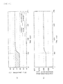
- Figs. 9(a) and 9(b) are graphs illustrating an example, as a comparative example, of temperature management according to a conventional method using the PID control.
- Fig. 9(a) illustrates a change over time of a CPU temperature
- Fig. 9(b) illustrates a change over time of a control signal (a fan revolution speed indicated value) to be supplied from a control unit to a cooling fan unit.
- the target temperature is set to 80°C, and the transition from the idle state to the operational state takes place 500 seconds later.
- a solid line in Fig. 9(a) is an actual measurement value of the CPU temperature and a dashed line therein is the target temperature.
- Figs. 10(a) and 10(b) are graphs illustrating an example of temperature management by the temperature management system according to this embodiment.
- Fig. 10 (a) illustrates a change over time of a CPU temperature
- Fig. 10(b) illustrates a change over time of a control signal (a fan revolution speed indicated value) to be supplied from the control unit 30 to the cooling fan unit 12.
- the target temperature is set to 80°C, and the transition from the idle state to the operational state takes place 500 seconds later.
- the fan revolution speed indicated value quickly responds to the transition and the number of revolutions of each cooling fan 12a is increased. Then, the CPU temperature reaches the target temperature about 1100 seconds later, and the CPU temperature is maintained at the target temperature thereafter.
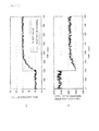
- Figs. 11(a) and 11(b) are graphs illustrating the example, as the comparative example, of the temperature management according to the conventional method in a situation where observation noise is added.
- Fig. 11(a) illustrates a change over time of a CPU temperature
- Fig. 11(b) illustrates a change over time of a fan revolution speed indicated value being a control signal to be supplied from the control unit to the cooling fan unit.
- an initial value of the target temperature is set to 70°C and the target temperature is changed to 80°C about 200 seconds later.
- a solid line in Fig. 11(a) is an actual measurement value of the CPU temperature and a dashed line therein is the target temperature.
- Figs. 12(a) and 12(b) are graphs illustrating the example of the temperature management by the temperature management system according to this embodiment in a situation where observation noise is added.
- Fig. 12(a) illustrates a change over time of a CPU temperature
- Fig. 12 (b) illustrates a change over time of a control signal (a fan revolution speed indicated value) to be supplied from the control unit 30 to the cooling fan unit 12.
- an initial value of the target temperature is set to 70°C and the target temperature is changed to 80°C about 200 seconds later.
- a solid line in Fig. 12(a) is an actual measurement value of the CPU temperature and a dashed line therein is the target temperature.
- the temperature management system As clear from Figs. 12(a) and 12(b) , the temperature management system according to this embodiment generates a smooth control signal which can be followed by the actual cooling fan unit 12 even when the controlled variable is oscillatory. In addition, the response is kept from significant deteriorating as compared to the conventional method, and the cooling control is achieved properly.
- Fig. 13 is a block diagram illustrating a temperature management system according to a second embodiment.
- This embodiment is different from the first embodiment in that the determination as to whether or not a computer is in the idle state is made on the basis of power consumption of the computer.
- the rest of the configurations are basically the same as those of the first embodiment. For this reason, in Fig. 13 , the same constituents as those in Fig. 4 will be denoted by the same reference numerals and detailed descriptions thereof will be omitted.
- this embodiment will also be described with reference to Fig. 1 and Fig. 2 .
- each computer 14 is provided with a power consumption sensor 61, and power consumption of each computer 14 is inputted on a real-time basis from the corresponding power consumption sensor 61 to a control unit 30a.
- Each power consumption sensor is an example of a power consumption detection unit.
- each computer 14 is small in the idle state, and grows larger as an operating rate of the corresponding CPU 14a becomes higher. For this reason, it is possible to determine whether or not the computer 14 is in the idle state by monitoring its power consumption.
- Fig. 14 is a functional block diagram describing a configuration of the control unit 30a.
- the same constituents as those in Fig. 5 will be denoted by the same reference numerals and detailed descriptions thereof will be omitted.
- An output from each power consumption sensor 61 provided to the corresponding computer 14 is transferred to a maximum power consumption calculation unit 62.
- the maximum power consumption calculation unit 62 extracts a maximum value of the power consumption (maximum power consumption) out of values of power consumption of the computers 14 provided by the respective power consumption sensors 61.
- the idle state determination unit 44 determines whether or not the computers 14 are in the idle state by using the CPU temperature provided through the high-level temperature calculation unit 42 and the maximum power consumption provided from the maximum power consumption calculation unit 62.
- the idle state determination unit 44 determines as being in the idle state when the maximum power consumption provided from the maximum power consumption calculation unit 62 is lower than a preset value or when the CPU temperature provided from the high-level temperature calculation unit 42 is lower than a preset temperature.
- the idle state determination unit 44 determines as not being in the idle state when the maximum power consumption provided from the maximum power consumption calculation unit 62 is equal or above the preset value and when the CPU temperature provided from the high-level temperature calculation unit 42 is equal to or above the preset temperature.
- the accumulation value correction unit 45 corrects the accumulation value of the integrator 50 in the manipulated variable calculation unit 40 when the idle state determination unit 44 determines that the computers 14 are in the idle state.
- Fig. 15 and Fig. 16 are flowcharts illustrating a temperature management method by the temperature management system according to this embodiment. Operations of the control unit 30a will be described further in detail with reference to the flowcharts. Here, it is assumed that the control unit 30a performs a sequence of the operations illustrated in Fig. 15 and Fig. 16 for each rack 13 and at each given time interval (such as every second).
- step S31 the control unit 30a acquires the target value set to the target value setting unit 31.
- step S32 the control unit 30a acquires the CPU temperatures of the computers 14 through the temperature sensors 32. Meanwhile, in step S33, the control unit 30a acquires the values of power consumption of the computers 14 through the power consumption sensors 61.
- step S34 the control unit 30a extracts a CPU temperature from the measurement values of the CPU temperatures of the computers 14 acquired through the temperature sensors 32, the CPU temperature being equal to or above the reference value ⁇ .
- step S35 the control unit 30a determines whether or not at least one CPU temperature was successfully extracted.
- the process proceeds to step S36 if no CPU temperature is extracted, i.e., if there is no CPU 14a with the CPU temperature exceeding the reference value 0 in the targeted rack 13.
- the control unit 30a decreases the reference value ⁇ just by the amount ⁇ calculated by the above-described formula (1). Thereafter, the process proceeds to step S34.
- control unit 30a repeats the step S34 to step S36 until at least one CPU temperature exceeding the reference value ⁇ is extracted.
- step S34 When at least one CPU temperature exceeding the reference value ⁇ is extracted in step S34, the process proceeds to step S37 from step S35.
- step S37 the control unit 30a sets the CPU temperature acquired in step S34 to the controlled variable y(s).
- the average value or the highest value thereof is set to the controlled variable y(s).
- step S34 to step S37 are executed by the high-level temperature calculation unit 42.
- step S38 the control unit 30a performs the smoothing in order to smooth the fluctuation in the controlled variable y(s).
- the smoothing is executed by the controlled variable smoothing unit 43.
- step S39 the control unit 30a calculates the deviation e(t) between the target value r(t) acquired from the target value setting unit 31 and the smoothed controlled variable y(s). This calculation is performed by the calculator 40a.
- step S40 the control unit 30a calculates the proportional manipulated variable u P (t) depending on the deviation e(t) by the above-described formula (5). Moreover, the control unit 30a calculates the derivative manipulated variable u D (t) depending on the amount of change in the deviation e(t) by the above-described formula (6).
- step S41 the control unit 30a uses the maximum power consumption calculation unit 62 to extract the maximum power consumption from the values of power consumption of the computers 14 inputted from the power consumption sensors 61.
- step S42 the control unit 30a uses the CPU temperature extracted by the high-level temperature calculation unit 42 and the maximum power consumption extracted by the maximum power consumption calculation unit 62 to determine whether or not the computers 14 are in the idle state by the idle state determination unit 44.
- the idle state determination unit 44 determines as being in the idle state when the CPU temperature extracted by the high-level temperature calculation unit 42 is lower than the preset temperature or when the maximum power consumption extracted by the maximum power consumption calculation unit 62 is lower than the preset value. On the other hand, the idle state determination unit 44 determines as not being in the idle state when the CPU temperature extracted by the high-level temperature calculation unit 42 is equal to or above the preset temperature and when the maximum power consumption extracted by the maximum power consumption calculation unit 62 is equal to or above the preset value.
- step S43 in the case of the determination as being in the idle state (in the case of YES) in step S42, or proceeds to step S44 from step S42 in the case of the determination as not being in the idle state (in the case of NO) therein.
- step S43 the accumulation value S(t) of the integrator 50 is re-set to the predetermined value ⁇ as indicated in the above-described formula (10). In this embodiment as well, ⁇ is set equal to 0. Thereafter, the integral manipulated variable u I (t) is calculated by the above-described formula (11). Then, the process proceeds to step S45.
- step S44 the integral manipulated variable u I (t) is calculated by the above-described formula (11). After the integral manipulated variable u I (t) is calculated, the process proceeds to step S45.
- step S45 the control unit 30a calculates the sum of the outputs from the proportional manipulated variable calculation module 51, the derivative manipulated variable calculation module 52, and the integral manipulated variable calculation module 53 by the above-described formula (14) with using the calculator 40b, and outputs the calculated sum as the manipulated variable u(t).
- step S46 the control unit 30a corrects the manipulated variable u(t) by the above-described formula (16) or formula (17), as needed, such that the manipulated variable u(t) falls within the range of u min ⁇ u(t) ⁇ u max .
- step S47 the control unit 30a smoothes the manipulated variable u(t) with the manipulated variable smoothing unit 55.
- step S48 the control unit 30a generates the control signal for the cooling fan unit 12 from the manipulated variable u(t) by using the control signal generation unit 56.
- step S49 the control unit 30a controls the number of revolutions of each cooling fan 12a in the cooling fan unit 12 on the basis of the control signal.
- the determination as to whether or not the computers 14 are in the idle state is made on the basis of the power consumption of the computer 14.
- control unit 30a re-sets the accumulation value S(t) of the integrator 50 of the integral manipulated variable calculation module 53 to the predetermined value ⁇ in the idle state as in the case of the first embodiment. For this reason, the deviation is not excessively accumulated in the integrator 50 in the idle state, so that the control is properly conducted after the transition from the idle state to the operational state, and the computers 14 are cooled stably and efficiently.
- the controlled variable y(s) is smoothed by the controlled variable smoothing unit 43 and the manipulated variable u(t) is smoothed by the manipulated variable smoothing unit 55. Accordingly, a useful and smooth manipulated variable is generated instead of an oscillatory manipulated variable which is in fact impracticable.
- the CPU temperatures are directly measured by using the temperature sensors 32, and the cooling fan unit 12 is controlled in such a way that the CPU temperature at a high level does not exceed the target value.
- the cooling fan unit 12 is controlled in such a way that the CPU temperature at a high level does not exceed the target value.
- Fig. 17 is a functional block diagram describing a configuration of a control unit of a temperature management system according to a third embodiment.
- This embodiment is different from the first embodiment in that an accumulation value upper-lower limit saturation determination unit and an accumulation value saturation correction unit are provided in the control unit.
- the rest of the configurations are basically the same as those of the first embodiment.
- the same constituents as those in Fig. 5 will be denoted by the same reference numerals and detailed descriptions thereof will be omitted.
- this embodiment will also be described with reference to Fig. 1 and Fig. 2 .
- an accumulation value upper-lower limit saturation determination unit 71 and an accumulation value saturation correction unit 72 are provided in a control unit 30b.
- the accumulation value upper-lower limit saturation determination unit 71 determines whether or not the accumulation value of the integrator 50 falls within a predetermined range.
- the accumulation value saturation correction unit 72 corrects the accumulation value of the integrator 50 with a preset upper limit when the accumulation value upper-lower limit saturation determination unit 71 determines that the accumulation value is greater than the upper limit.
- the accumulation value saturation correction unit 72 corrects the accumulation value of the integrator 50 with a preset lower limit when the accumulation value upper-lower limit saturation determination unit 71 determines that the accumulation value is smaller than the lower limit.
- Fig. 18 and Fig. 19 are flowcharts illustrating a temperature management method by the temperature management system according to this embodiment. Operations of the control unit 30b will be described further in detail with reference to the flowcharts. Here, it is assumed that the control unit 30b performs a sequence of the operations illustrated in Fig. 18 and Fig. 19 for each rack 13 and at each given time interval (such as every second).
- step S51 the control unit 30b acquires the target value set to the target value setting unit 31.
- step S52 the control unit 30b acquires the CPU temperatures of the computers 14 through the temperature sensors 32.
- step S53 the control unit 30b acquires the temperature of the air on the intake face side of the rack 13 through the temperature sensor 33.
- step S54 the control unit 30b extracts a CPU temperature from the measurement values of the CPU temperatures of the computers 14 acquired through the temperature sensors 32, the CPU temperature being equal to or above the reference value ⁇ .
- step S55 the control unit 30b determines whether or not at least one CPU temperature was successfully extracted.
- the process proceeds to step S56 if no CPU temperature is extracted, i.e., if there is no CPU 14a with the CPU temperature exceeding the reference value ⁇ in the targeted rack 13.
- the control unit 30b decreases the reference value ⁇ just by the amount ⁇ calculated by the above-described formula (1). Thereafter, the process proceeds to step S54.
- control unit 30b repeats the step S54 to step S56 until at least one CPU temperature exceeding the reference value ⁇ is extracted.
- step S54 When at least one CPU temperature exceeding the reference value ⁇ is extracted in step S54, the process proceeds to step S57 from step S55.
- step S57 the control unit 30b sets the CPU temperature acquired in step S54 to the controlled variable y(s).
- the average value or the highest value thereof is set to the controlled variable y(s).
- step S54 to step S57 are executed by the high-level temperature calculation unit 42.
- step S58 the control unit 30b performs the smoothing in order to smooth the fluctuation in the controlled variable y(s).
- the smoothing is executed by the controlled variable smoothing unit 43.
- step S59 the control unit 30b calculates the deviation e(t) between the target value r(t) acquired from the target value setting unit 31 and the smoothed controlled variable y(s) by the above-described formula (4). This calculation is performed by the calculator 40a.
- step S60 the control unit 30b calculates the proportional controlled variable u P (t) depending on the deviation e(t) by the above-described formula (5). Moreover, the control unit 30b calculates the derivative manipulated variable u D (t) depending on the amount of change in the deviation e(t) by the above-described formula (6).
- step S61 the control unit 30b refers to the idle state determination map 41, and finds the CPU reference temperature Ta base in the idle state by using the temperature Tc of the air on the intake face side of the rack 13 and the reference temperature Ta of the CPU in the idle state.
- step S62 the control unit 30b determines whether or not the computers 14 are in the idle state.
- the computers 14 are determined to be in the idle state when the value of the CPU temperature (the controlled variable y(s)) transferred from the high-level temperature calculation unit 42 is smaller than the value Ta base + ⁇ i.e., when Ta base + ⁇ > y(s) holds true.
- the value ⁇ is set to 5°C as in the first embodiment.
- step S63 in the case of the determination as being in the idle state (in the case of YES) in step S62, or proceeds to step S64a from step S62 in the case of the determination as not being in the idle state (in the case of NO) therein.
- step S63 the accumulation value S(t) of the integrator 50 is re-set to the predetermined value ⁇ .
- ⁇ is set equal to 0.
- the integral manipulated variable u I (t) is calculated by the above-described formula (11), and the process proceeds to step S65.
- step S64a the control unit 30b calculates the integral manipulated variable u I (t) by the above-described formula (11).
- step S64b the control unit 30b corrects the accumulation value S(t) of the integrator 50 by the following formula (18) or formula (19), as needed, such that the accumulation value S(t) of the integrator 50 satisfies S min ⁇ S(t) ⁇ S max .
- S min is the preset lower limit of the accumulation value and S max is the preset upper limit of the accumulation value.
- step S65 the control unit 30b calculates the sum of the outputs from the proportional manipulated variable calculation module 51, the derivative manipulated variable calculation module 52, and the integral manipulated variable calculation module 53 by using the calculator 40b, and outputs the calculated sum as the manipulated variable u(t).
- step S66 the control unit 30b corrects the manipulated variable u(t), as needed, such that the manipulated variable u(t) falls within the range of u min ⁇ u(t) ⁇ u max .
- step S67 the control unit 30b smoothes the manipulated variable u(t) with the manipulated variable smoothing unit 55.
- step S68 the control unit 30b generates the control signal for the cooling fan unit 12 from the manipulated variable u(t) by using the control signal generation unit 56.
- step S69 the control unit 30b controls the number of revolutions of each cooling fan 12a in the cooling fan unit 12 on the basis of the control signal.
- control unit 30b re-sets the accumulation value S(t) of the integrator 50 of the integral manipulated variable calculation module 53 to the predetermined value ⁇ in the idle state. For this reason, the deviation is not excessively accumulated in the integrator 50 in the idle state, so that the control is properly conducted after the transition from the idle state to the operational state.
- the accumulation value of the integrator 50 is corrected, as needed, at the time not in the idle state such that the accumulation value falls within the predetermined range. For this reason, even when the target value is set in such a range which the control cannot follow according to the conventional method, the deviation is not excessively accumulated in the integrator 50 and the computer 14 is cooled stably and efficiently.
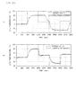
- Figs. 20(a) and 20(b) are graphs illustrating an example of temperature management by the temperature management system according to this embodiment in comparison with the conventional method.
- a dashed line indicates the target value and a solid line indicates the controlled variable.
- the target value is set to such a value which the controlled variable cannot follow.
- the control quickly functions once the target value falls within a followable range as illustrated in Fig. 20(b) .
- Each of the first to third embodiments describes the temperature management system for the modular data center, which is designed to cool the computers by introducing the outside air into the room.
- the disclosed technique can also be used for temperature management of a data center of a mode not introducing the outside air into the room.
- Fig. 21 is a view illustrating an example of such a data center.
- a plurality of racks 83, an air conditioner (a package air conditioner) 81, and a cooling fan unit 82 are disposed inside a computer room 80.
- a plurality of computers 84 are housed in each rack 83.
- the cooling fan unit 82 includes a plurality of cooling fans 82a.
- a section between the cooling fan unit 82 and intake faces of the racks 83 is a cold aisle 91, and a space on an exhaust face side of the racks 83 is a hot aisle 92.
- a partition plate 85 is disposed above the cooling fan unit 82 and the racks 83.
- a space above the partition plate 85 is defined as a warm air flow passage 93 configured to bring the air discharged to the hot aisle 92 back to the air conditioner 81.
- the low-temperature air blown out of an air outlet of the air conditioner 81 is sent to the cold aisle 91 by the cooling fan unit 82, and is introduced from an intake face of each rack 83 into the rack 83.
- the air introduced into the rack 83 cools electronic components such as CPUs while passing through the computers 84 and the temperature of the air is increased. Then, the air is discharged from an exhaust face of each rack 83 to the hot aisle 92.
- the air discharged to the hot aisle 92 passes through the warm air flow passage 93 and moves to an intake port of the air conditioner 81. Then, the temperature of the air is adjusted by the air conditioner 81, and the air is blown out of the air outlet again.
- the adoption of any of the temperature management systems described in the first to third embodiments, for example, enables the proper cooling depending on the temperatures of the CPUs while suppressing reduction in substantive operating rate of the computers 84.
- each rack 13 a plurality of computers 14 disposed on an upper side of each rack 13 may be defined as one group and a plurality of computers 14 disposed on a lower side thereof may be defined as another group, for example, and a cooling fan 12a on an upper side of each cooling fan unit 12 and a cooling fan 12a on a lower side thereof may be controlled individually.
Landscapes
- Engineering & Computer Science (AREA)
- Physics & Mathematics (AREA)
- Theoretical Computer Science (AREA)
- Microelectronics & Electronic Packaging (AREA)
- General Engineering & Computer Science (AREA)
- Thermal Sciences (AREA)
- General Physics & Mathematics (AREA)
- Computer Hardware Design (AREA)
- Human Computer Interaction (AREA)
- Aviation & Aerospace Engineering (AREA)
- Computing Systems (AREA)
- Quality & Reliability (AREA)
- Cooling Or The Like Of Electrical Apparatus (AREA)
- Feedback Control In General (AREA)
- Air Conditioning Control Device (AREA)
Abstract
Description
- The present invention relates to a temperature management system.
- With the recent advent of an advanced information society, an amount of data treated by computers has been increasing, and there has been a growing trend of collective management of many computers disposed in the same room in a facility such as a data center. For example, in such a data center, many racks (server racks) are disposed in a computer room and a plurality of computers (servers) are housed in each of the racks. Moreover, a large volume of jobs are efficiently processed by being organically distributed to the computers depending on operational states of the computers.
- Meanwhile, each computer generates a large amount of heat during operation. A rise in temperature inside the computer may cause a malfunction or a failure. Accordingly, cooling air is taken into each rack by using a cooling fan, and the heat generated inside the computer is discharged to the outside of the rack.
- In the meantime, the data center consumes a lot of electric power and there is a demand for reducing power consumption from the viewpoint of energy conservation. In order to prevent failures or malfunctions of the computers due to the heat, a conceivable solution is to constantly rotate cooling fans each at the maximum number of revolutions. Nevertheless, there are many cooling fans disposed in the data center. If such many cooling fans are constantly rotated each at the maximum number of revolutions, the power consumption is increased and the reduction in power consumption is therefore unachievable.
- Hence, in order to reduce the power consumption in the facility such as the data center, it is important to efficiently operate cooling equipment in accordance with the operational states of the computers.
-
- Patent Document 1: Japanese Laid-open Patent Publication No.
2008-227127 - Patent Document 2: Japanese Laid-open Patent Publication No.
2011-222029 - Non-patent Document 1: ASTROM, K., and HAGGLUND, T.: "PID controllers: theory, design and tuning" (ISA Press, Research Triangle Park, North Carolina, 1995)
- An object of the invention is to provide a temperature management system, which is capable of suppressing deterioration in control performance attributed to reset windup, and efficiently cooling an electronic device such as a computer.
- According to an aspect of the disclosed technique, there is provided a temperature management system which includes: a plurality of electronic devices each changing an amount of heat generation depending on its operational state; temperature detection units configured to individually detect temperatures of the plurality of electronic devices; a cooling device configured to cool the plurality of electronic devices; and a control unit configured to control the cooling device depending on outputs from the temperature detection units. Here, the control unit includes: an idle state determination unit configured to determine whether or not the electronic devices are in an idle state; a manipulated variable calculation unit provided with an integrator and configured to calculate a manipulated variable by using a difference between a target value and a controlled variable; and an accumulation value correction unit configured to correct an accumulation value of the integrator with a predetermined value when the idle state determination unit determines that the electronic devices are in the idle state.
- According to the above-described temperature management system, the accumulation value of the integrator is corrected with the predetermined value in the idle state. Thus, the temperature management system can suppress deterioration in control performance attributed to reset windup, and stably and properly cool an electronic device.
-
- [
Fig. 1] Fig. 1 is a schematic top view illustrating an example of a data center to which a temperature management system according to a first embodiment is applied. - [
Fig. 2] Fig. 2 is a schematic side view of the same data center. - [
Fig. 3] Fig. 3 is a schematic top view illustrating an example of introducing outside air into an outside air introduction portion through evaporative cooling devices in the same data center. - [
Fig. 4] Fig. 4 is a block diagram illustrating the temperature management system according to the first embodiment. - [
Fig. 5] Fig. 5 is a functional block diagram describing a configuration of a control unit. - [
Fig. 6] Fig. 6 is a view illustrating an example of an idle state determination map stored in an idle state determination map storage unit. - [
Fig. 7] Fig. 7 is a (first) flowchart illustrating a temperature management method by the temperature management system according to the first embodiment. - [
Fig. 8] Fig. 8 is a (second) flowchart illustrating the temperature management method by the temperature management system according to the first embodiment. - [
Fig. 9] Figs. 9(a) and 9(b) are graphs illustrating an example (a comparative example) of temperature management according to a conventional method using PID control. - [
Fig. 10] Figs. 10(a) and 10(b) are graphs illustrating an example of temperature management by the temperature management system according to the first embodiment. - [
Fig. 11] Figs. 11(a) and 11(b) are graphs illustrating the example (the comparative example) of the temperature management according to the conventional method in a situation where observation noise is added. - [
Fig. 12] Figs. 12(a) and 12(b) are graphs illustrating the example of the temperature management by the temperature management system according to the first embodiment in a situation where observation noise is added. - [
Fig. 13] Fig. 13 is a block diagram illustrating a temperature management system according to a second embodiment. - [
Fig. 14] Fig. 14 is a functional block diagram describing a configuration of a control unit of the temperature management system according to the second embodiment. - [
Fig. 15] Fig. 15 is a (first) flowchart illustrating a temperature management method by the temperature management system according to the second embodiment. - [
Fig. 16] Fig. 16 is a (second) flowchart illustrating the temperature management method by the temperature management system according to the second embodiment. - [
Fig. 17] Fig. 17 is a functional block diagram describing a configuration of a control unit of a temperature management system according to a third embodiment. - [
Fig. 18] Fig. 18 is a (first) flowchart illustrating a temperature management method by the temperature management system according to the third embodiment. - [
Fig. 19] Fig. 19 is a (second) flowchart illustrating the temperature management method by the temperature management system according to the third embodiment. - [
Fig. 20] Figs. 20(a) and 20(b) are graphs illustrating an example of temperature management by the temperature management system according to the third embodiment in comparison with the conventional method. - [
Fig. 21] Fig. 21 is a view illustrating an example of a data center applying a mode in which no outside air is introduced into a room. - Before descriptions are provided for embodiments, a prelude for facilitating the understanding of the embodiments will be explained below.
- As described previously, in order to reduce power consumption in a facility such as a data center, it is important to efficiently operate cooling equipment in accordance with operational states of electronic devices.
- To this end, a conceivable solution is to measure a temperature of each computer, for example, and to subject each cooling fan to PID (proportional-integral-derivative) control depending on a deviation between the measured temperature and a target temperature thereof. However, application of general PID control to the cooling of the computer may cause a situation in which the control does not temporarily function when the computer transitions from an idle state to an operational state, and it may take a long period of time to achieve the target temperature.
- This is attributed to occurrence of a phenomenon called reset windup, in which a deviation between a target value and a controlled variable is excessively accumulated in an integrator of a PID control unit when the computer is in the idle state. Due to the reset windup, the control does not function after the computer transitions from the idle state to the operational state until elimination of the deviation which is excessively accumulated in the integrator.
- In general, in the PID control, the reset windup occurs at the time of transition to a condition where the controlled variable cannot follow the target value, or at the time when the target value is set in such a range that the controlled variable cannot follow under a certain condition.
- Each of the following embodiments will describe a temperature management system, which is capable of suppressing deterioration in control performance attributed to the reset windup, and efficiently cooling a computer.
-
Fig. 1 is a schematic top view illustrating an example of a data center to which a temperature management system according to a first embodiment is applied, andFig. 2 is a schematic side view of the same data center. Note that this embodiment describes a modular data center as an example, which is configured to cool computers (servers) by utilizing outside air. - The modular data center illustrated as the example in
Fig. 1 and Fig. 2 includes a container (an enclosure) 10 having a rectangular parallelepiped shape,cooling fan units 12 disposed inside thecontainer 10, and a plurality ofracks 13. Eachrack 13 houses a plurality ofcomputers 14. - An
intake port 11a is provided to one of two faces of thecontainer 10 which are opposite from each other, while anexhaust port 11b is provided to the other face thereof. Meanwhile, apartition plate 15 is disposed above a space between thecooling fan units 12 and theracks 13. - Each cooling
fan unit 12 is provided with a plurality of coolingfans 12a. Moreover, theintake port 11a and theexhaust port 11b are each provided with a rainwater infiltration prevention plate to prevent infiltration of rainwater, and an insect screen to prevent intrusion of insects and the like. In this embodiment, each coolingfan unit 12 is provided for eachrack 13 as illustrated inFig. 1 . - A space inside the
container 10 is segmented into an outsideair introduction portion 21, acold aisle 22, ahot aisle 23, and a warmair circulation passage 24 by using the coolingfan units 12, theracks 13, and thepartition plate 15. The outsideair introduction portion 21 is a space between theintake port 11a and coolingfan units 12. Thecold aisle 22 is a space between the coolingfan units 12 and theracks 13. Thehot aisle 23 is a space between theracks 13 and theexhaust port 11b. - Each
rack 13 is disposed such that its face on thecold aisle 22 side is an intake face and its face on thehot aisle 23 side is an exhaust face. - The warm
air circulation passage 24 is a space above theracks 13 and thepartition plate 15, which connects between thehot aisle 23 and the outsideair introduction portion 21. The warmair circulation passage 24 is provided with adamper 17 for adjusting an amount of circulation of the warm air. - In the modular data center illustrated as the example in
Fig. 1 and Fig. 2 , the outsideair introduction portion 21 is provided withevaporative cooling devices 16, each of which is configured to reduce a temperature of air to be introduced to the outsideair introduction portion 21 by utilizing vaporization heat of water when an outside air temperature is high. - In the above-described modular data center, the cooling
fans 12a in the coolingfan units 12 are rotated whereby the air (outside air) is introduced to the outsideair introduction portion 21 through theintake port 11a. Then, the air introduced into the outsideair introduction portion 21 moves to thecold aisle 22 through the coolingfan units 12, further enters theracks 13 from the intake faces of theracks 13, and cools thecomputers 14. - The air (warm air) with an increased temperature as a consequence of cooling the
computers 14 is discharged from the exhaust faces of theracks 13 to thehot aisle 23, and is discharged from theexhaust port 11b to the outside. - When the outside air temperature is high, the
damper 17 is set to a closed state whereby the warm air is kept from moving from thehot aisle 23 to the outsideair introduction portion 21. When the outside air temperature is even higher, the water is supplied to theevaporative cooling devices 16, and the outside air is introduced into the outsideair introduction portion 21 through theevaporative cooling devices 16 as illustrated inFig. 3 . When the outside air passes through eachevaporative cooling device 16, the water evaporates and draws the vaporization heat from its surroundings. As a consequence, the air at a lower temperature than the outside air temperature is introduced to the outsideair introduction portion 21. - On the other hand, the
damper 17 is set to an open state when the outside air temperature is low and the temperature of the air to be introduced into theracks 13 is likely to fall below the preset lowest allowable temperature. Thus, part of the warm air returns from thehot aisle 23 to the outsideair introduction portion 21 through the warmair circulation passage 24, thereby increasing the temperature of the air to be introduced into theracks 13. -
Fig. 4 is a block diagram illustrating the temperature management system according to the first embodiment. - As illustrated in
Fig. 4 , the temperature management system according to this embodiment includestemperature sensors 32 configured to individually detect temperatures ofCPUs 14a of therespective computers 14, atemperature sensor 33 configured to detect a temperature of the air on the intake face side of theracks 13, acontrol unit 30, a targetvalue setting unit 31, and the coolingfan units 12. Eachcomputer 14 is an example of an electronic device, eachtemperature sensor 32 is an example of a temperature detection unit, and each coolingfan unit 12 is an example of a cooling device. - The
temperature sensor 32 is formed in the same chip as the one in which theCPU 14a is provided. Thetemperature sensor 32 transmits the temperature of theCPU 14a to thecontrol unit 30 through a communication device (not illustrated) provided inside thecomputer 14. - In this embodiment, transmission and reception of signals between the
control unit 30 and thecomputer 14 are assumed to be performed by way of UDP (user datagram protocol) communication. However, the communication between thecontrol unit 30 and thecomputer 14 is not limited to the UDP communication. Meanwhile, in this embodiment, the temperature sensor disposed in the same chip as the one in which theCPU 14a is provided is used as thetemperature sensor 32. Here, a temperature sensor disposed in close contact with a package of theCPU 14a may be used instead. - The
control unit 30 is configured to include a microcomputer, an FPGA (field-programmable gate array), a PLC (programmable logic controller), or the like. Instead, a certain one of thecomputers 14 in therack 13 may be caused to read a dedicated program and used as thecontrol unit 30. - A target value of a CPU temperature is set to the target
value setting unit 31. The target value only needs to be such a temperature lower than the highest allowable temperature of theCPU 14a, and the target value can be changed depending on an operating condition of theCPU 14a. In this embodiment, an initial value of the target value is set to 80°C. - The
control unit 30 controls the coolingfan units 12 depending on outputs from thetemperature sensors value setting unit 31. Details of operations of thecontrol unit 30 will be described later. -
Fig. 5 is a functional block diagram describing a configuration of thecontrol unit 30. As illustrated inFig. 5 , thecontrol unit 30 includes a manipulatedvariable calculation unit 40, an idle state determinationmap storage unit 41, a high-leveltemperature calculation unit 42, a controlledvariable smoothing unit 43, an idlestate determination unit 44, an accumulationvalue correction unit 45, an upper-lowerlimit restriction unit 54, a manipulatedvariable smoothing unit 55, and a controlsignal generation unit 56. - Meanwhile, the manipulated
variable calculation unit 40 includescalculators variable calculation module 51, a derivative manipulatedvariable calculation module 52, and an integral manipulatedvariable calculation module 53. The proportional manipulatedvariable calculation module 51 is configured to include a proportionalgain setting unit 46. In the meantime, the derivative manipulatedvariable calculation module 52 is configured to include a derivativegain setting unit 47 and adifferentiator 48. Furthermore, the integral manipulatedvariable calculation module 53 is configured to include an integralgain setting unit 49 and anintegrator 50. - The idle state determination
map storage unit 41 stores an idle state determination map indicating relations between the temperature of the air on the intake face side of therack 13 and a reference temperature of theCPU 14a in the idle state.Fig. 6 illustrates an example of the idle state determination map stored in the idle state determinationmap storage unit 41. - As illustrated in
Fig. 6 , the idle state determination map describes a relation between an intake air temperature Tc (the temperature of the air on the intake face side of the rack 13) and a reference temperature Ta (a CPU temperature) in the idle state for each data code. - The high-level
temperature calculation unit 42 receives inputs of the CPU temperatures of thecomputers 14 from thetemperature sensors 32, extracts a CPU temperature exceeding a reference value as described later, and outputs the extracted CPU temperature to the idlestate determination unit 44 and the controlledvariable smoothing unit 43. The controlledvariable smoothing unit 43 performs smoothing of the CPU temperature inputted from the high-leveltemperature calculation unit 42, and outputs a resultant value to the manipulatedvariable calculation unit 40. - The idle
state determination unit 44 receives an input of the temperature of the air on the intake face side of theracks 13 through thetemperature sensor 33, and receives an input of the CPU temperature through the high-level calculation unit 42. Then, the idlestate determination unit 44 determines whether or not theCPUs 14a are in the idle state by using the inputted data and the idle state determination map stored in the idle state determinationmap storage unit 41. - A result of determination by the idle
state determination unit 44 is transferred to the accumulationvalue correction unit 45. When the idlestate determination unit 44 determines that theCPUs 14a are in the idle state, the accumulationvalue correction unit 45 corrects an accumulation value of theintegrator 50 in the manipulatedvariable calculation unit 40 as described later. - The
calculator 40a of the manipulatedvariable calculation unit 40 calculates a difference between the target value set to the targetvalue setting unit 31 and the CPU temperature (a smoothed CPU temperature) inputted from the controlledvariable smoothing unit 43. - The proportional manipulated
variable calculation module 51 calculates a proportional manipulated variable uP from an output from thecalculator 40a by using the proportionalgain setting unit 46. Meanwhile, the derivative manipulatedvariable calculation module 52 calculates a derivative manipulated variable uD from the output from thecalculator 40a by using the derivativegain setting unit 47 and thedifferentiator 48. Furthermore, the integral manipulatedvariable calculation module 53 calculates an integral manipulated variable uI from the output from thecalculator 40a by using the integralgain setting unit 49 and theintegrator 50. - The
calculator 40b sums up the proportional manipulated variable uP outputted from the proportional manipulatedvariable calculation module 51, the derivable manipulated variable uD outputted from the derivative manipulatedvariable calculation module 52, and the integral manipulated variable uI outputted from the integral manipulatedvariable calculation module 53. A manipulated variable to be outputted from thecalculator 40b is outputted to the upper-lowerlimit restriction unit 54 as an output from the manipulatedvariable calculation unit 40. - The upper-lower
limit restriction unit 54 transfers the manipulated variable, which is outputted from the manipulatedvariable calculation unit 40, to the manipulatedvariable smoothing unit 55. However, the upper-lowerlimit restriction unit 54 transfers a preset upper limit to the manipulatedvariable smoothing unit 55 as the manipulated variable when the manipulated variable outputted from the manipulatedvariable calculation unit 40 is greater than the upper limit, and transfers a lower limit to the manipulatedvariable smoothing unit 55 as the manipulated variable when the aforementioned manipulated variable is smaller than the lower limit. - The manipulated
variable smoothing unit 55 smoothes the manipulated variable transferred from the upper-lowerlimit restriction unit 54. The controlsignal generation unit 56 generates a control signal corresponding to the manipulated variable outputted from the manipulatedvariable smoothing unit 55. Each coolingfan 12a in the coolingfan unit 12 is rotated at the number of revolutions corresponding to the control signal outputted from the controlsignal generation unit 56. -
Fig. 7 andFig. 8 are flowcharts illustrating a temperature management method by the temperature management system according to this embodiment. The operations of thecontrol unit 30 will be described further in detail with reference to the flowcharts. Here, it is assumed that thecontrol unit 30 performs a sequence of the operations illustrated inFig. 7 andFig. 8 for eachrack 13 and at each given time interval (such as every second). - First, in step S11, the
control unit 30 acquires the target value set to the targetvalue setting unit 31. - Next, the process proceeds to step S12 where the
control unit 30 acquires the CPU temperatures of thecomputers 14 through thetemperature sensors 32. Meanwhile, in step S13, thecontrol unit 30 acquires the temperature of the air on the intake face side of therack 13 through thetemperature sensor 33. - Next, the process proceeds to step S14 where the
control unit 30 extracts a CPU temperature from measurement values of the CPU temperatures of thecomputers 14 acquired through thetemperature sensors 32, the CPU temperature being equal to or above a reference value θ. - Here, the reference value θ is defined as 0 < θ < Tmax. Tmax is a temperature at which the
CPU 14a of eachcomputer 14 starts throttling, for example. When the temperature of theCPU 14a reaches Tmax, theCPU 14a automatically reduces its clock so as to prevent the temperature of theCPU 14a from rising to Tmax and above. In this embodiment, an initial value of the reference value θ is set to 100°C. - Next, in step S15, the
control unit 30 determines whether or not at least one CPU temperature was successfully extracted. The process proceeds to step S16 if no CPU temperature is extracted, i.e., if there is noCPU 14a with the CPU temperature exceeding the reference value θ in the targetedrack 13. Thereafter, thecontrol unit 30 decreases the reference value θ just by an amount φ, and then the process proceeds to step S14. The amount φ is calculated by the following formula (1). - [Formula 1]

- Here, α is a constant which determines an amount of decrease in value of the reference value θ, which is an arbitrary value smaller than 1. However, delicate temperature control is infeasible if the value α is too large, and the control becomes complicated if the value α is too small. In this embodiment, the value α is set to 0.01.
- In this way, the
control unit 30 repeats the step S14 to step S16 until at least one CPU temperature exceeding the reference value θ is extracted. - When at least one CPU temperature exceeding the reference value θ is extracted in step S14, the process proceeds to step S17 from step S15. In step S17, the
control unit 30 sets the CPU temperature acquired in step S14 to a controlled variable y(s). When there are two or more CPU temperatures extracted in step S14, either an average value or the highest value thereof is set to the controlled variable y(s). - The above-described operations from step S14 to step S17 are executed by the high-level
temperature calculation unit 42. - Thereafter, the process proceeds to step S18 where the
control unit 30 performs smoothing in order to smooth a fluctuation in the controlled variable y(s). The smoothing is executed by the controlledvariable smoothing unit 43. - This embodiment applies a primary delay transfer function F(s) as a smoothing method. In this case, if a controlled variable before the smoothing is yin, a controlled variable yout after the smoothing is calculated by the following formula (2).
- [Formula 2]

- Here, the primary delay transfer function F(s) is expressed by the following formula (3).
- [Formula 3]

- In formula (3), s is a Laplace operator. Meanwhile, Tf is a filter time constant. The controlled variable becomes smoother through time as the value Tf is greater. However, a control response becomes slower instead. In this embodiment, Tf is set equal to 5.
- Instead of the primary delay transfer function, it is also possible to perform the smoothing by using Kalman filter and the like.
- Next, the process proceeds to step S19 where the
control unit 30 calculates a deviation e(t) between a target value r(t) acquired from the targetvalue setting unit 31 and the smoothed controlled variable y(t), by the following formula (4). - [Formula 4]

- This calculation is performed by the
calculator 40a. - Meanwhile, in step S20, the
control unit 30 calculates a proportional manipulated variable uP(t) depending on the deviation e(t) by the following formula (5). - [Formula 5]

- Moreover, the
control unit 30 calculates a derivative manipulated variable uD(t) depending on an amount of change in the deviation e(t) by the following formula (6). - [Formula 6]

- Here, KP is a proportional gain and KD is a derivative gain. The derivative gain KD can also be expressed with the proportional gain KP and derivative time TD as in the following formula (7).
- [Formula 7]

- These calculations are performed by the proportional manipulated
variable calculation module 51 and the derivative manipulatedvariable calculation module 52 of thecalculator 40. - Next, the process proceeds to step S21 where the
control unit 30 refers to the idle state determination map stored in the idle state determinationmap storage unit 41. Then, the temperature of the air on the intake face side is used as a search key to acquire a predetermined number of data codes having values close to the temperature of the air on the intake face side. Thereafter, interpolation processing is performed as described later by using the temperature Tc of the air on the intake face side of therack 13 and the reference temperature Ta of the CPU in the idle state, thereby finding a CPU reference temperature Tabase in the idle state. - For example, when the linear interpolation is performed by acquiring two points (Tci, Tai) and (Tci+1, Tai+1) from the idle state determination map, the CPU reference temperature Tabase in the idle state is calculated from a current intake air temperature Tcin by the following formula (8).
- [Formula 8]

- If the interpolation is performed by acquiring three or more points from the idle state determination map, then it is also possible to use Lagrange's interpolation as indicated in the following formula (9).
- [Formula 9]

- Here, M is the number of the data acquired. In addition, it is also possible to use spline interpolation and the like.
- Next, in step S22, the
control unit 30 determines whether or not thecomputers 14 are in the idle state. Here, thecomputers 14 are determined to be in the idle state when the value of the CPU temperature (the controlled variable y(s)) transferred from the high-leveltemperature calculation unit 42 is smaller than a value Tabase+β, i.e., when Tabase+β > y(s) holds true. - Here, β is a parameter for taking into account a fluctuation in the CPU temperature in the idle state, which is a positive number. In this embodiment, β is set to 5°C. When the value β is large, a criterion for determination of the idle state is relaxed and a temperature range applicable to the determination as being in the idle state is expanded. When the value β is small, the criterion for determination of the idle state becomes strict and the temperature range applicable to the determination as being in the idle state is narrowed.
- The process proceeds to step S23 in the case of the determination as being in the idle state (in the case of YES) in step S22, or proceeds to step S24 from step S22 in the case of the determination as not being in the idle state (in the case of NO) therein.
- In step S23, an accumulation value S(t) of the
integrator 50 is re-set to a predetermined value γ as indicated in the following formula (10). In this embodiment, γ is set equal to 0. - [Formula 10]

- Thereafter, an integral manipulated variable uI (t) is calculated by the following formula (11) with the integral manipulated
variable calculation module 53. Then, the process proceeds to step S25. - On the other hand, when the process proceeds to step S24 from step S22, the
control unit 30 calculates the integral manipulated variable uI(t) by the following formula (11) with the integral manipulatedvariable calculation module 53. - [Formula 11]

- Here, S(t) is the accumulated value of the
integrator 50 and KI is an integral gain. The integral gain KI is expressed with the proportional gain KP and integral time TI as indicated in the following formula (12). - [Formula 12]

- The integral calculation is expressed with a discretized equation in order to facilitate the explanation. In this embodiment, the integral calculation is to be calculated by the following formula (13) by adopting the modified Euler method (the trapezoidal rule).
- [Formula 13]

- Here, Δt is step time. After the integral manipulated variable uI(t) is calculated, the process proceeds to step S25.
- In step S25, the
control unit 30 calculates a sum of the outputs from the proportional manipulatedvariable calculation module 51, the derivative manipulatedvariable calculation module 52, and the integral manipulatedvariable calculation module 53 by using thecalculator 40b, and outputs the calculated sum as the manipulated variable. Since this embodiment explains the case of subjecting the coolingfan unit 12 to the PID control, a manipulated variable u(t) is calculated by the following formula (14). - [Formula 14]

- Here, if the cooling
fan unit 12 is subjected to PI control, then the manipulated variable u(t) is calculated by the following formula (15). - [Formula 15]

- Next, in step S26, the
control unit 30 corrects the manipulated variable u(t) by the following formula (16) or formula (17), as needed, such that the manipulated variable u(t) falls within a range of umin ≤ u(t) ≤ umax. - [Formula 16]

- [Formula 17]

- This operation is performed by the upper-lower
limit restriction unit 54. - Next, the process proceeds to step S27 where the
control unit 30 smoothes the manipulated variable u(t) by using the above-described primary delay transfer function, for example. Here, the value of the filter time constant Tf when smoothing the manipulated variable u(t) is set to Tf= 10. - Next, the process proceeds to step S28 where the
control unit 30 generates the control signal for the coolingfan unit 12 from the manipulated variable u(t) by using the controlsignal generation unit 56. In this embodiment, a PWM (pulse width modulation) signal is to be generated in order to control the coolingfans 12a. - Subsequently, the process proceeds to step S29 where the
control unit 30 controls the number of revolutions of each coolingfan 12a in the coolingfan unit 12 on the basis of the control signal. - As described above, in this embodiment, the
control unit 30 re-sets the accumulation value S(t) of theintegrator 50 of the integral manipulatedvariable calculation module 53 to the predetermined value γ in the idle state. For this reason, the deviation is not excessively accumulated in theintegrator 50 in the idle state, so that the control is properly conducted after the transition from the idle state to the operational state, and thecomputers 14 are cooled stably and efficiently. - Meanwhile, in this embodiment, the controlled variable y(s) is smoothed by the controlled
variable smoothing unit 43 and the manipulated variable u(t) is smoothed by the manipulatedvariable smoothing unit 55. Accordingly, a useful and smooth manipulated variable is generated instead of an oscillatory manipulated variable which is in fact impracticable. - Furthermore, in this embodiment, the CPU temperatures are directly measured by using the
temperature sensors 32, and the coolingfan unit 12 is controlled in such a way that the CPU temperature at a high level does not exceed the target value. Thus, it is possible to perform the cooling efficiently depending on the CPU temperatures. Accordingly, reduction in power consumption of the data center can be achieved while avoiding occurrence of a problem attributed to the heat of thecomputer 14. -
Figs. 9(a) and 9(b) are graphs illustrating an example, as a comparative example, of temperature management according to a conventional method using the PID control.Fig. 9(a) illustrates a change over time of a CPU temperature andFig. 9(b) illustrates a change over time of a control signal (a fan revolution speed indicated value) to be supplied from a control unit to a cooling fan unit. - In the example illustrated in
Figs. 9 (a) and 9(b) , the target temperature is set to 80°C, and the transition from the idle state to the operational state takesplace 500 seconds later. Note that a solid line inFig. 9(a) is an actual measurement value of the CPU temperature and a dashed line therein is the target temperature. - As clear from
Figs. 9(a) and 9(b) , in the conventional method, when the CPU temperature is increased 500 seconds later and exceeds the target value thereafter, the control does not function for some time and a large overshoot of the CPU temperature is observed. -
Figs. 10(a) and 10(b) are graphs illustrating an example of temperature management by the temperature management system according to this embodiment.Fig. 10 (a) illustrates a change over time of a CPU temperature andFig. 10(b) illustrates a change over time of a control signal (a fan revolution speed indicated value) to be supplied from thecontrol unit 30 to the coolingfan unit 12. In the example illustrated inFigs. 10(a) and 10(b) , the target temperature is set to 80°C, and the transition from the idle state to the operational state takesplace 500 seconds later. - As clear from
Figs. 10(a) and 10(b) , according to the temperature management system according to this embodiment, when thecomputers 14 transition from the idle state to the operational state, the fan revolution speed indicated value quickly responds to the transition and the number of revolutions of each coolingfan 12a is increased. Then, the CPU temperature reaches the target temperature about 1100 seconds later, and the CPU temperature is maintained at the target temperature thereafter. -
Figs. 11(a) and 11(b) are graphs illustrating the example, as the comparative example, of the temperature management according to the conventional method in a situation where observation noise is added.Fig. 11(a) illustrates a change over time of a CPU temperature andFig. 11(b) illustrates a change over time of a fan revolution speed indicated value being a control signal to be supplied from the control unit to the cooling fan unit. - In the example illustrated in
Figs. 11(a) and 11(b) , an initial value of the target temperature is set to 70°C and the target temperature is changed to 80°C about 200 seconds later. Note that a solid line inFig. 11(a) is an actual measurement value of the CPU temperature and a dashed line therein is the target temperature. - As clear from
Figs. 11(a) and 11(b) , it turns out that the conventional method generates the control signal (the fan revolution speed indicated value), which is oscillatory and can hardly be followed by the actualcooling fan unit 12. -
Figs. 12(a) and 12(b) are graphs illustrating the example of the temperature management by the temperature management system according to this embodiment in a situation where observation noise is added.Fig. 12(a) illustrates a change over time of a CPU temperature andFig. 12 (b) illustrates a change over time of a control signal (a fan revolution speed indicated value) to be supplied from thecontrol unit 30 to the coolingfan unit 12. - In the example illustrated in
Figs. 12(a) and 12(b) , an initial value of the target temperature is set to 70°C and the target temperature is changed to 80°C about 200 seconds later. Note that a solid line inFig. 12(a) is an actual measurement value of the CPU temperature and a dashed line therein is the target temperature. - As clear from
Figs. 12(a) and 12(b) , the temperature management system according to this embodiment generates a smooth control signal which can be followed by the actualcooling fan unit 12 even when the controlled variable is oscillatory. In addition, the response is kept from significant deteriorating as compared to the conventional method, and the cooling control is achieved properly. -
Fig. 13 is a block diagram illustrating a temperature management system according to a second embodiment. This embodiment is different from the first embodiment in that the determination as to whether or not a computer is in the idle state is made on the basis of power consumption of the computer. The rest of the configurations are basically the same as those of the first embodiment. For this reason, inFig. 13 , the same constituents as those inFig. 4 will be denoted by the same reference numerals and detailed descriptions thereof will be omitted. In addition, this embodiment will also be described with reference toFig. 1 and Fig. 2 . - As illustrated in
Fig. 13 , in the temperature management system according to this embodiment, eachcomputer 14 is provided with apower consumption sensor 61, and power consumption of eachcomputer 14 is inputted on a real-time basis from the correspondingpower consumption sensor 61 to acontrol unit 30a. Each power consumption sensor is an example of a power consumption detection unit. - The power consumption of each
computer 14 is small in the idle state, and grows larger as an operating rate of thecorresponding CPU 14a becomes higher. For this reason, it is possible to determine whether or not thecomputer 14 is in the idle state by monitoring its power consumption. -
Fig. 14 is a functional block diagram describing a configuration of thecontrol unit 30a. InFig. 14 , the same constituents as those inFig. 5 will be denoted by the same reference numerals and detailed descriptions thereof will be omitted. - An output from each
power consumption sensor 61 provided to thecorresponding computer 14 is transferred to a maximum powerconsumption calculation unit 62. The maximum powerconsumption calculation unit 62 extracts a maximum value of the power consumption (maximum power consumption) out of values of power consumption of thecomputers 14 provided by the respectivepower consumption sensors 61. - The idle
state determination unit 44 determines whether or not thecomputers 14 are in the idle state by using the CPU temperature provided through the high-leveltemperature calculation unit 42 and the maximum power consumption provided from the maximum powerconsumption calculation unit 62. - For example, the idle
state determination unit 44 determines as being in the idle state when the maximum power consumption provided from the maximum powerconsumption calculation unit 62 is lower than a preset value or when the CPU temperature provided from the high-leveltemperature calculation unit 42 is lower than a preset temperature. - On the other hand, the idle
state determination unit 44 determines as not being in the idle state when the maximum power consumption provided from the maximum powerconsumption calculation unit 62 is equal or above the preset value and when the CPU temperature provided from the high-leveltemperature calculation unit 42 is equal to or above the preset temperature. - Meanwhile, the accumulation
value correction unit 45 corrects the accumulation value of theintegrator 50 in the manipulatedvariable calculation unit 40 when the idlestate determination unit 44 determines that thecomputers 14 are in the idle state. -
Fig. 15 andFig. 16 are flowcharts illustrating a temperature management method by the temperature management system according to this embodiment. Operations of thecontrol unit 30a will be described further in detail with reference to the flowcharts. Here, it is assumed that thecontrol unit 30a performs a sequence of the operations illustrated inFig. 15 andFig. 16 for eachrack 13 and at each given time interval (such as every second). - First, in step S31, the
control unit 30a acquires the target value set to the targetvalue setting unit 31. - Next, the process proceeds to step S32 where the
control unit 30a acquires the CPU temperatures of thecomputers 14 through thetemperature sensors 32. Meanwhile, in step S33, thecontrol unit 30a acquires the values of power consumption of thecomputers 14 through thepower consumption sensors 61. - Next, the process proceeds to step S34 where the
control unit 30a extracts a CPU temperature from the measurement values of the CPU temperatures of thecomputers 14 acquired through thetemperature sensors 32, the CPU temperature being equal to or above the reference value θ. - Next, in step S35, the
control unit 30a determines whether or not at least one CPU temperature was successfully extracted. The process proceeds to step S36 if no CPU temperature is extracted, i.e., if there is noCPU 14a with the CPU temperature exceeding thereference value 0 in the targetedrack 13. Then, thecontrol unit 30a decreases the reference value θ just by the amount φ calculated by the above-described formula (1). Thereafter, the process proceeds to step S34. - In this way, the
control unit 30a repeats the step S34 to step S36 until at least one CPU temperature exceeding the reference value θ is extracted. - When at least one CPU temperature exceeding the reference value θ is extracted in step S34, the process proceeds to step S37 from step S35. In step S37, the
control unit 30a sets the CPU temperature acquired in step S34 to the controlled variable y(s). When there are two or more CPU temperatures extracted in step S34, either the average value or the highest value thereof is set to the controlled variable y(s). - The above-described operations from step S34 to step S37 are executed by the high-level
temperature calculation unit 42. - Thereafter, the process proceeds to step S38 where the
control unit 30a performs the smoothing in order to smooth the fluctuation in the controlled variable y(s). The smoothing is executed by the controlledvariable smoothing unit 43. - Next, the process proceeds to step S39 where the
control unit 30a calculates the deviation e(t) between the target value r(t) acquired from the targetvalue setting unit 31 and the smoothed controlled variable y(s). This calculation is performed by thecalculator 40a. - Next, the process proceeds to step S40 where the
control unit 30a calculates the proportional manipulated variable uP (t) depending on the deviation e(t) by the above-described formula (5). Moreover, thecontrol unit 30a calculates the derivative manipulated variable uD(t) depending on the amount of change in the deviation e(t) by the above-described formula (6). - These calculations are performed by the proportional manipulated
variable calculation module 51 and the derivative manipulatedvariable calculation module 52 of thecalculator 40. - Next, the process proceeds to step S41 where the
control unit 30a uses the maximum powerconsumption calculation unit 62 to extract the maximum power consumption from the values of power consumption of thecomputers 14 inputted from thepower consumption sensors 61. - Next, the process proceeds to step S42 where the
control unit 30a uses the CPU temperature extracted by the high-leveltemperature calculation unit 42 and the maximum power consumption extracted by the maximum powerconsumption calculation unit 62 to determine whether or not thecomputers 14 are in the idle state by the idlestate determination unit 44. - Specifically, the idle
state determination unit 44 determines as being in the idle state when the CPU temperature extracted by the high-leveltemperature calculation unit 42 is lower than the preset temperature or when the maximum power consumption extracted by the maximum powerconsumption calculation unit 62 is lower than the preset value. On the other hand, the idlestate determination unit 44 determines as not being in the idle state when the CPU temperature extracted by the high-leveltemperature calculation unit 42 is equal to or above the preset temperature and when the maximum power consumption extracted by the maximum powerconsumption calculation unit 62 is equal to or above the preset value. - The process proceeds to step S43 in the case of the determination as being in the idle state (in the case of YES) in step S42, or proceeds to step S44 from step S42 in the case of the determination as not being in the idle state (in the case of NO) therein.
- In step S43, the accumulation value S(t) of the
integrator 50 is re-set to the predetermined value γ as indicated in the above-described formula (10). In this embodiment as well, γ is set equal to 0. Thereafter, the integral manipulated variable uI(t) is calculated by the above-described formula (11). Then, the process proceeds to step S45. - On the other hand, when the process proceeds to step S44 from step S42, the integral manipulated variable uI(t) is calculated by the above-described formula (11). After the integral manipulated variable uI(t) is calculated, the process proceeds to step S45.
- In step S45, the
control unit 30a calculates the sum of the outputs from the proportional manipulatedvariable calculation module 51, the derivative manipulatedvariable calculation module 52, and the integral manipulatedvariable calculation module 53 by the above-described formula (14) with using thecalculator 40b, and outputs the calculated sum as the manipulated variable u(t). - Next, in step S46, the
control unit 30a corrects the manipulated variable u(t) by the above-described formula (16) or formula (17), as needed, such that the manipulated variable u(t) falls within the range of umin ≤ u(t) ≤ umax. - Next, the process proceeds to step S47 where the
control unit 30a smoothes the manipulated variable u(t) with the manipulatedvariable smoothing unit 55. - Next, the process proceeds to step S48 where the
control unit 30a generates the control signal for the coolingfan unit 12 from the manipulated variable u(t) by using the controlsignal generation unit 56. - Subsequently, the process proceeds to step S49 where the
control unit 30a controls the number of revolutions of each coolingfan 12a in the coolingfan unit 12 on the basis of the control signal. - As described above, in this embodiment, the determination as to whether or not the
computers 14 are in the idle state is made on the basis of the power consumption of thecomputer 14. - In this embodiment, the
control unit 30a re-sets the accumulation value S(t) of theintegrator 50 of the integral manipulatedvariable calculation module 53 to the predetermined value γ in the idle state as in the case of the first embodiment. For this reason, the deviation is not excessively accumulated in theintegrator 50 in the idle state, so that the control is properly conducted after the transition from the idle state to the operational state, and thecomputers 14 are cooled stably and efficiently. - Meanwhile, in this embodiment, the controlled variable y(s) is smoothed by the controlled
variable smoothing unit 43 and the manipulated variable u(t) is smoothed by the manipulatedvariable smoothing unit 55. Accordingly, a useful and smooth manipulated variable is generated instead of an oscillatory manipulated variable which is in fact impracticable. - Furthermore, in this embodiment, the CPU temperatures are directly measured by using the
temperature sensors 32, and the coolingfan unit 12 is controlled in such a way that the CPU temperature at a high level does not exceed the target value. Thus, it is possible to perform the cooling efficiently depending on the CPU temperatures. Accordingly, reduction in power consumption of the data center can be achieved while avoiding occurrence of a problem attributed to the heat of thecomputer 14. -
Fig. 17 is a functional block diagram describing a configuration of a control unit of a temperature management system according to a third embodiment. This embodiment is different from the first embodiment in that an accumulation value upper-lower limit saturation determination unit and an accumulation value saturation correction unit are provided in the control unit. The rest of the configurations are basically the same as those of the first embodiment. For this reason, inFig. 17 , the same constituents as those inFig. 5 will be denoted by the same reference numerals and detailed descriptions thereof will be omitted. In addition, this embodiment will also be described with reference toFig. 1 and Fig. 2 . - As illustrated in
Fig. 17 , in the temperature management system according to this embodiment, an accumulation value upper-lower limitsaturation determination unit 71 and an accumulation valuesaturation correction unit 72 are provided in acontrol unit 30b. The accumulation value upper-lower limitsaturation determination unit 71 determines whether or not the accumulation value of theintegrator 50 falls within a predetermined range. The accumulation valuesaturation correction unit 72 corrects the accumulation value of theintegrator 50 with a preset upper limit when the accumulation value upper-lower limitsaturation determination unit 71 determines that the accumulation value is greater than the upper limit. The accumulation valuesaturation correction unit 72 corrects the accumulation value of theintegrator 50 with a preset lower limit when the accumulation value upper-lower limitsaturation determination unit 71 determines that the accumulation value is smaller than the lower limit. -
Fig. 18 andFig. 19 are flowcharts illustrating a temperature management method by the temperature management system according to this embodiment. Operations of thecontrol unit 30b will be described further in detail with reference to the flowcharts. Here, it is assumed that thecontrol unit 30b performs a sequence of the operations illustrated inFig. 18 andFig. 19 for eachrack 13 and at each given time interval (such as every second). - First, in step S51, the
control unit 30b acquires the target value set to the targetvalue setting unit 31. - Next, the process proceeds to step S52 where the
control unit 30b acquires the CPU temperatures of thecomputers 14 through thetemperature sensors 32. Meanwhile, in step S53, thecontrol unit 30b acquires the temperature of the air on the intake face side of therack 13 through thetemperature sensor 33. - Next, the process proceeds to step S54 where the
control unit 30b extracts a CPU temperature from the measurement values of the CPU temperatures of thecomputers 14 acquired through thetemperature sensors 32, the CPU temperature being equal to or above the reference value θ. - Next, in step S55, the
control unit 30b determines whether or not at least one CPU temperature was successfully extracted. The process proceeds to step S56 if no CPU temperature is extracted, i.e., if there is noCPU 14a with the CPU temperature exceeding the reference value θ in the targetedrack 13. Then, thecontrol unit 30b decreases the reference value θ just by the amount φ calculated by the above-described formula (1). Thereafter, the process proceeds to step S54. - In this way, the
control unit 30b repeats the step S54 to step S56 until at least one CPU temperature exceeding the reference value θ is extracted. - When at least one CPU temperature exceeding the reference value θ is extracted in step S54, the process proceeds to step S57 from step S55. In step S57, the
control unit 30b sets the CPU temperature acquired in step S54 to the controlled variable y(s). When there are two or more CPU temperatures extracted in step S54, either the average value or the highest value thereof is set to the controlled variable y(s). - The above-described operations from step S54 to step S57 are executed by the high-level
temperature calculation unit 42. - Thereafter, the process proceeds to step S58 where the
control unit 30b performs the smoothing in order to smooth the fluctuation in the controlled variable y(s). The smoothing is executed by the controlledvariable smoothing unit 43. - Next, the process proceeds to step S59 where the
control unit 30b calculates the deviation e(t) between the target value r(t) acquired from the targetvalue setting unit 31 and the smoothed controlled variable y(s) by the above-described formula (4). This calculation is performed by thecalculator 40a. - Next, the process proceeds to step S60 where the
control unit 30b calculates the proportional controlled variable uP(t) depending on the deviation e(t) by the above-described formula (5). Moreover, thecontrol unit 30b calculates the derivative manipulated variable uD(t) depending on the amount of change in the deviation e(t) by the above-described formula (6). - These calculations are performed by the proportional manipulated
variable calculation module 51 and the derivative manipulatedvariable calculation module 52 of thecalculator 40. - Next, the process proceeds to step S61 where the
control unit 30b refers to the idlestate determination map 41, and finds the CPU reference temperature Tabase in the idle state by using the temperature Tc of the air on the intake face side of therack 13 and the reference temperature Ta of the CPU in the idle state. - Next, in step S62, the
control unit 30b determines whether or not thecomputers 14 are in the idle state. Here, thecomputers 14 are determined to be in the idle state when the value of the CPU temperature (the controlled variable y(s)) transferred from the high-leveltemperature calculation unit 42 is smaller than the value Tabase+β i.e., when Tabase+β > y(s) holds true. In this embodiment, the value β is set to 5°C as in the first embodiment. - The process proceeds to step S63 in the case of the determination as being in the idle state (in the case of YES) in step S62, or proceeds to step S64a from step S62 in the case of the determination as not being in the idle state (in the case of NO) therein.
- In step S63, the accumulation value S(t) of the
integrator 50 is re-set to the predetermined value γ. In this embodiment, γ is set equal to 0. Thereafter, the integral manipulated variable uI(t) is calculated by the above-described formula (11), and the process proceeds to step S65. - On the other hand, when the process proceeds to step S64a from step S62, the
control unit 30b calculates the integral manipulated variable uI(t) by the above-described formula (11). - Then, the process proceeds to step S64b where the
control unit 30b corrects the accumulation value S(t) of theintegrator 50 by the following formula (18) or formula (19), as needed, such that the accumulation value S(t) of theintegrator 50 satisfies Smin ≤ S(t) ≤ Smax. - [Formula 18]

- [Formula 19]

- Here, Smin is the preset lower limit of the accumulation value and Smax is the preset upper limit of the accumulation value. In this embodiment, the value Smax was set to 100 (Smax= 100) and the value Smin was set to -100 (Smin= -100) based on a result of tuning.
- Next, in step S65, the
control unit 30b calculates the sum of the outputs from the proportional manipulatedvariable calculation module 51, the derivative manipulatedvariable calculation module 52, and the integral manipulatedvariable calculation module 53 by using thecalculator 40b, and outputs the calculated sum as the manipulated variable u(t). - Next, in step S66, the
control unit 30b corrects the manipulated variable u(t), as needed, such that the manipulated variable u(t) falls within the range of umin ≤ u(t) ≤ umax. - Next, the process proceeds to step S67 where the
control unit 30b smoothes the manipulated variable u(t) with the manipulatedvariable smoothing unit 55. - Next, the process proceeds to step S68 where the
control unit 30b generates the control signal for the coolingfan unit 12 from the manipulated variable u(t) by using the controlsignal generation unit 56. - Subsequently, the process proceeds to step S69 where the
control unit 30b controls the number of revolutions of each coolingfan 12a in the coolingfan unit 12 on the basis of the control signal. - As described above, in this embodiment, the
control unit 30b re-sets the accumulation value S(t) of theintegrator 50 of the integral manipulatedvariable calculation module 53 to the predetermined value γ in the idle state. For this reason, the deviation is not excessively accumulated in theintegrator 50 in the idle state, so that the control is properly conducted after the transition from the idle state to the operational state. - Moreover, in this embodiment, the accumulation value of the
integrator 50 is corrected, as needed, at the time not in the idle state such that the accumulation value falls within the predetermined range. For this reason, even when the target value is set in such a range which the control cannot follow according to the conventional method, the deviation is not excessively accumulated in theintegrator 50 and thecomputer 14 is cooled stably and efficiently. -
Figs. 20(a) and 20(b) are graphs illustrating an example of temperature management by the temperature management system according to this embodiment in comparison with the conventional method. In each ofFigs. 20(a) and 20(b) , a dashed line indicates the target value and a solid line indicates the controlled variable. Here, in each of a period from 1000 second later to 2000 seconds later and a period from 3000 seconds later to 4000 second later, the target value is set to such a value which the controlled variable cannot follow. - In the conventional method, when the target value is set to such a value which the controlled variable cannot follow, there occurs a situation where the control does not function for some time even after the target value falls within a followable range as illustrated in
Fig. 20(a) . - On the other hand, in the temperature management system according to this embodiment, even when the target value is set to such a value which the controlled variable cannot follow, the control quickly functions once the target value falls within a followable range as illustrated in
Fig. 20(b) . - Each of the first to third embodiments describes the temperature management system for the modular data center, which is designed to cool the computers by introducing the outside air into the room. However, the disclosed technique can also be used for temperature management of a data center of a mode not introducing the outside air into the room.
Fig. 21 is a view illustrating an example of such a data center. - A plurality of
racks 83, an air conditioner (a package air conditioner) 81, and a coolingfan unit 82 are disposed inside acomputer room 80. A plurality ofcomputers 84 are housed in eachrack 83. Meanwhile, the coolingfan unit 82 includes a plurality of coolingfans 82a. - A section between the cooling
fan unit 82 and intake faces of theracks 83 is acold aisle 91, and a space on an exhaust face side of theracks 83 is ahot aisle 92. Meanwhile, apartition plate 85 is disposed above the coolingfan unit 82 and theracks 83. A space above thepartition plate 85 is defined as a warmair flow passage 93 configured to bring the air discharged to thehot aisle 92 back to theair conditioner 81. - The low-temperature air blown out of an air outlet of the
air conditioner 81 is sent to thecold aisle 91 by the coolingfan unit 82, and is introduced from an intake face of eachrack 83 into therack 83. The air introduced into therack 83 cools electronic components such as CPUs while passing through thecomputers 84 and the temperature of the air is increased. Then, the air is discharged from an exhaust face of eachrack 83 to thehot aisle 92. - The air discharged to the
hot aisle 92 passes through the warmair flow passage 93 and moves to an intake port of theair conditioner 81. Then, the temperature of the air is adjusted by theair conditioner 81, and the air is blown out of the air outlet again. - In the above-described data center, the adoption of any of the temperature management systems described in the first to third embodiments, for example, enables the proper cooling depending on the temperatures of the CPUs while suppressing reduction in substantive operating rate of the
computers 84. - Although the above-described embodiments explain the temperature management systems configured to manage the temperatures of the computers, the disclosed technique is also applicable to cooling of electronic devices other than the computers.
- Meanwhile, the above-described embodiments explain the case of defining the plurality of
computers 14 housed in thesame rack 13 as one group, and controlling the coolingfan unit 12 corresponding to each group (each rack 13). Instead, a plurality ofcomputers 14 disposed on an upper side of eachrack 13 may be defined as one group and a plurality ofcomputers 14 disposed on a lower side thereof may be defined as another group, for example, and a coolingfan 12a on an upper side of each coolingfan unit 12 and a coolingfan 12a on a lower side thereof may be controlled individually.
Claims (14)
- A temperature management system characterized in that the system comprises:a plurality of electronic devices each changing an amount of heat generation depending on its operational state;temperature detection units configured to individually detect temperatures of the plurality of electronic devices;a cooling device configured to cool the plurality of electronic devices; anda control unit configured to control the cooling device depending on outputs from the temperature detection units, andthe control unit includes:an idle state determination unit configured to determine whether or not the electronic devices are in an idle state;a manipulated variable calculation unit provided with an integrator and configured to calculate a manipulated variable by using a difference between a target value and a controlled variable; andan accumulation value correction unit configured to correct an accumulation value of the integrator with a predetermined value when the idle state determination unit determines that the electronic devices are in the idle state.
- The temperature management system according to claim 1, characterized in that the control unit subjects the cooling device to PID (proportional-integral-derivative) control or PI (proportional-integral) control.
- The temperature management system according to claim 1 or 2, characterized in that the control unit further includes:a high-level temperature calculation unit configured to extract a temperature equal to or above a reference value from the temperatures detected by the temperature detection units, and to set the extracted temperature to the controlled variable;a controlled variable smoothing unit configured to smooth the controlled variable outputted from the high-level temperature calculation unit; anda control signal generation unit configured to generate a control signal to control the cooling device based on the manipulated variable outputted from the manipulated variable calculation unit.
- The temperature management system according to claim 3, characterized in that the control unit further includes an upper-lower limit restriction unit disposed between the manipulated variable calculation unit and the control signal generation unit, and configured to restrict an upper limit and a lower limit of the manipulated variable outputted from the manipulated variable calculation unit.
- The temperature management system according to claim 4, characterized in that the control unit further includes a manipulated variable smoothing unit disposed between the upper-lower limit restriction unit and the control signal generation unit, and configured to smooth the manipulated variable.
- The temperature management system according to any one of claims 1 to 5, characterized in that the control unit includes an accumulation value saturation correction unit configured to restrict an upper limit and a lower limit of the accumulation value of the integrator when the idle state determination unit determines that the electronic devices are not in the idle state.
- The temperature management system according to any one of claims 1 to 6, characterized in that the system further comprises:a temperature sensor configured to detect a temperature of air outside the electronic devices, andthe idle state determination unit determines whether or not the electronic devices are in the idle state based on the temperatures detected by the temperature detection units and the temperature of the air detected by the temperature sensor.
- The temperature management system according to any one of claims 1 to 6, characterized in that the system further comprises:power consumption detection units configured to detect values of power consumption of the electronic devices, andthe idle state determination unit determines whether or not the electronic devices are in the idle state based on the temperatures of the electronic devices detected by the temperature detection units and the values of power consumption detected by the power consumption detection units.
- The temperature management system according to any one of claims 3 to 8, characterized in that when no temperature equal to or above the reference value is extracted, the control unit decreases a level of the reference value until at least one temperature equal to or above the reference value is extracted.
- The temperature management system according to any one of claims 3 to 8, characterized in that the control unit divides the plurality of electronic devices into a plurality of groups, extracts the temperature equal to above the reference value for each of the groups, and controls the cooling device for each of the groups.
- The temperature management system according to any one of claims 1 to 10, characterized in that the cooling device is a cooling fan unit including a plurality of cooling fans.
- The temperature management system according to any one of claims 1 to 11, characterized in that the electronic devices are computers.
- The temperature management system according to claim 12, characterized in that the computers are housed in a rack.
- The temperature management system according to claim 13, characterized in that outside air is introduced into a room where the rack is disposed.
Applications Claiming Priority (1)
| Application Number | Priority Date | Filing Date | Title |
|---|---|---|---|
| PCT/JP2012/072417 WO2014037988A1 (en) | 2012-09-04 | 2012-09-04 | Temperature administration system |
Publications (3)
| Publication Number | Publication Date |
|---|---|
| EP2894524A1 true EP2894524A1 (en) | 2015-07-15 |
| EP2894524A4 EP2894524A4 (en) | 2016-08-31 |
| EP2894524B1 EP2894524B1 (en) | 2020-01-15 |
Family
ID=50236642
Family Applications (1)
| Application Number | Title | Priority Date | Filing Date |
|---|---|---|---|
| EP12884059.2A Active EP2894524B1 (en) | 2012-09-04 | 2012-09-04 | Temperature administration system |
Country Status (5)
| Country | Link |
|---|---|
| US (1) | US9645622B2 (en) |
| EP (1) | EP2894524B1 (en) |
| JP (1) | JP5975105B2 (en) |
| CN (1) | CN104603699B (en) |
| WO (1) | WO2014037988A1 (en) |
Cited By (1)
| Publication number | Priority date | Publication date | Assignee | Title |
|---|---|---|---|---|
| US20150156917A1 (en) * | 2012-09-04 | 2015-06-04 | Fujitsu Limited | Temperature management system |
Families Citing this family (23)
| Publication number | Priority date | Publication date | Assignee | Title |
|---|---|---|---|---|
| CN106407143B (en) * | 2015-07-29 | 2020-07-31 | 南京中兴新软件有限责任公司 | Method and device for controlling hot plug operation of CPU in mobile terminal |
| US20170354060A1 (en) * | 2016-06-03 | 2017-12-07 | Crestron Electronics, Inc. | Apparatus for cooling electronic circuitry |
| US11076501B2 (en) * | 2017-05-23 | 2021-07-27 | Crestron Electronics, Inc. | Apparatus for cooling electronic circuitry |
| US11711904B2 (en) * | 2016-06-03 | 2023-07-25 | Crestron Electronics, Inc. | Apparatus for cooling electronic circuitry |
| CN107882759B (en) * | 2016-09-29 | 2019-11-19 | 英业达科技有限公司 | Method and system for optimizing control parameters of cooling fan |
| TWI619887B (en) * | 2016-10-14 | 2018-04-01 | 英業達股份有限公司 | Method and system for optimizing cooling fan control parameters |
| US11076509B2 (en) | 2017-01-24 | 2021-07-27 | The Research Foundation for the State University | Control systems and prediction methods for it cooling performance in containment |
| WO2018158837A1 (en) * | 2017-02-28 | 2018-09-07 | パイオニア株式会社 | Temperature control device, temperature control method, computer program, and storage medium |
| US9846444B1 (en) * | 2017-06-07 | 2017-12-19 | Aic Inc. | Method for controlling and adjusting fans of electronic apparatus |
| CN109253099B (en) * | 2017-07-13 | 2021-08-03 | 中兴通讯股份有限公司 | A kind of base station fan control method and device |
| US10455742B2 (en) * | 2017-09-01 | 2019-10-22 | Bitmain Technologies Limited | Architecture for cryptocurrency mining operation |
| CN110579075B (en) * | 2018-06-11 | 2021-10-01 | 惠而浦(中国)股份有限公司 | Method and system for controlling variable frequency load rotating speed of refrigerator |
| US11096316B1 (en) * | 2018-09-05 | 2021-08-17 | Amazon Technologies, Inc. | Discrete set-point-based datacenter cooling based on evaporative cooling status |
| TWM582276U (en) | 2019-03-14 | 2019-08-11 | 國家中山科學研究院 | Active intelligent cooling system for base station |
| CN112049811B (en) * | 2019-06-05 | 2022-06-10 | 英业达科技有限公司 | Method for controlling the rotational speed of a device |
| US20210342243A1 (en) * | 2020-05-01 | 2021-11-04 | Dell Products L.P. | Systems and methods for system power capping based on component temperature margins |
| US11513934B2 (en) | 2020-07-24 | 2022-11-29 | Dell Products L.P. | System and method for service life management by actively reducing corrosive interactions |
| US11503736B2 (en) | 2020-07-24 | 2022-11-15 | Dell Products L.P. | System and method for service life management by passively reducing corrosive interactions |
| US11470746B2 (en) | 2020-07-24 | 2022-10-11 | Dell Products L.P. | System and method for mitigating corrosion based on service life management |
| CN113589682B (en) * | 2021-09-28 | 2021-12-28 | 南方电网调峰调频发电有限公司 | Main transformer cooler switching method and system |
| US12446183B2 (en) * | 2021-12-09 | 2025-10-14 | Lg Energy Solution, Ltd. | Charge-and-discharge test apparatus and control method thereof |
| US11706900B1 (en) * | 2022-01-14 | 2023-07-18 | Dell Products L.P. | Passive and active environmental management of an information handling system |
| CN119668976B (en) * | 2024-11-28 | 2025-07-18 | 江西舜浥星科技有限公司 | A server operation status monitoring and management system based on AI intelligence |
Family Cites Families (33)
| Publication number | Priority date | Publication date | Assignee | Title |
|---|---|---|---|---|
| JPS61121110A (en) * | 1984-11-19 | 1986-06-09 | Fujitsu Ltd | Servo controller |
| JPS6314047A (en) * | 1986-06-28 | 1988-01-21 | 三菱重工業株式会社 | Refrigerant flow controller for air conditioner for automobile |
| JPH01279304A (en) | 1988-05-02 | 1989-11-09 | Shinko Electric Co Ltd | Integral proportion compensator for servo control system |
| US4999557A (en) | 1988-05-02 | 1991-03-12 | Shinko Electric Co., Ltd. | Integration proportional controller in servo-control system |
| JPH02254501A (en) * | 1989-03-29 | 1990-10-15 | Matsushita Electric Ind Co Ltd | process control equipment |
| JPH0490216A (en) | 1990-08-01 | 1992-03-24 | Fujitsu Ltd | Phase comparator and phase locked loop circuit |
| JP3162827B2 (en) * | 1992-09-18 | 2001-05-08 | 三洋電機株式会社 | Temperature control device |
| JP3422339B2 (en) * | 1994-11-18 | 2003-06-30 | セイコーエプソン株式会社 | Image forming device |
| US6006168A (en) * | 1997-12-12 | 1999-12-21 | Digital Equipment Corporation | Thermal model for central processing unit |
| JP3994208B2 (en) * | 1998-05-14 | 2007-10-17 | 株式会社Ihi | Actuator control device |
| US6553271B1 (en) | 1999-05-28 | 2003-04-22 | Deka Products Limited Partnership | System and method for control scheduling |
| JP2001290504A (en) * | 2000-04-11 | 2001-10-19 | Yaskawa Electric Corp | Control device |
| JP2002044882A (en) * | 2000-07-27 | 2002-02-08 | Funai Electric Co Ltd | Electrical outlet device and power source control system |
| US7822967B2 (en) * | 2000-09-27 | 2010-10-26 | Huron Ip Llc | Apparatus, architecture, and method for integrated modular server system providing dynamically power-managed and work-load managed network devices |
| US20020138159A1 (en) * | 2001-03-26 | 2002-09-26 | Atkinson Lee W. | Temperature responsive power supply to minimize power consumption of digital logic without reducing system performance |
| JP2003056389A (en) * | 2001-08-10 | 2003-02-26 | Bosch Automotive Systems Corp | Fuel injection amount control method and device |
| US6938433B2 (en) * | 2002-08-02 | 2005-09-06 | Hewlett-Packard Development Company, Lp. | Cooling system with evaporators distributed in series |
| JP3808826B2 (en) * | 2002-12-25 | 2006-08-16 | 京セラミタ株式会社 | Motor control device |
| US20080066889A1 (en) * | 2003-02-19 | 2008-03-20 | Isothermal Systems Research | Heat exchanging fluid return manifold for a liquid cooling system |
| US6957544B2 (en) * | 2003-07-18 | 2005-10-25 | Hewlett-Packard Development Company, L.P. | Method and apparatus for regulating the operating temperature of electronic devices |
| JP2007239462A (en) * | 2006-03-03 | 2007-09-20 | Toyota Motor Corp | Air-fuel ratio control device for internal combustion engine |
| CN2932930Y (en) * | 2006-06-12 | 2007-08-08 | 庄智远 | One-way cold source flow cooling temperature control device |
| JP2008227127A (en) | 2007-03-13 | 2008-09-25 | Seiko Epson Corp | Cooling fan drive control system, projector, program, information storage medium, and cooling fan drive control method |
| CN201210278Y (en) * | 2008-02-28 | 2009-03-18 | 曲峰 | Cooling pad for notebook-type computer |
| US8224489B2 (en) * | 2008-03-03 | 2012-07-17 | Federspiel, Corporation | Method and apparatus for coordinating the control of HVAC units |
| CN101751108B (en) * | 2008-11-28 | 2012-12-26 | 英业达股份有限公司 | Computer system |
| CN101751053A (en) * | 2008-12-04 | 2010-06-23 | 鸿富锦精密工业(深圳)有限公司 | Fan drive circuit |
| JP4947221B2 (en) * | 2010-05-11 | 2012-06-06 | ダイキン工業株式会社 | Operation control device for air conditioner and air conditioner having the same |
| KR101501915B1 (en) * | 2011-06-02 | 2015-03-12 | 봇슈 가부시키가이샤 | Heater control device for oxygen concentration sensor |
| US8899060B2 (en) * | 2011-06-30 | 2014-12-02 | International Business Machines Corporation | Methods and apparatus for cooling electronics |
| WO2014037988A1 (en) * | 2012-09-04 | 2014-03-13 | 富士通株式会社 | Temperature administration system |
| US9582010B2 (en) * | 2013-03-14 | 2017-02-28 | Rackspace Us, Inc. | System and method of rack management |
| US9690270B2 (en) * | 2014-10-22 | 2017-06-27 | Xerox Corporation | Method and apparatus for cooling a device based on productivity of the device |
-
2012
- 2012-09-04 WO PCT/JP2012/072417 patent/WO2014037988A1/en not_active Ceased
- 2012-09-04 EP EP12884059.2A patent/EP2894524B1/en active Active
- 2012-09-04 CN CN201280075578.2A patent/CN104603699B/en not_active Expired - Fee Related
- 2012-09-04 JP JP2014534058A patent/JP5975105B2/en not_active Expired - Fee Related
-
2015
- 2015-02-09 US US14/617,084 patent/US9645622B2/en not_active Expired - Fee Related
Cited By (2)
| Publication number | Priority date | Publication date | Assignee | Title |
|---|---|---|---|---|
| US20150156917A1 (en) * | 2012-09-04 | 2015-06-04 | Fujitsu Limited | Temperature management system |
| US9645622B2 (en) * | 2012-09-04 | 2017-05-09 | Fujitsu Limited | Temperature management system |
Also Published As
| Publication number | Publication date |
|---|---|
| US20150156917A1 (en) | 2015-06-04 |
| CN104603699A (en) | 2015-05-06 |
| JPWO2014037988A1 (en) | 2016-08-08 |
| WO2014037988A1 (en) | 2014-03-13 |
| US9645622B2 (en) | 2017-05-09 |
| EP2894524A4 (en) | 2016-08-31 |
| JP5975105B2 (en) | 2016-08-23 |
| CN104603699B (en) | 2017-08-29 |
| EP2894524B1 (en) | 2020-01-15 |
Similar Documents
| Publication | Publication Date | Title |
|---|---|---|
| EP2894524B1 (en) | Temperature administration system | |
| EP2977852B1 (en) | Temperature management system | |
| DK2985563T3 (en) | Apparatus for controlling a cooling system | |
| EP3679773B1 (en) | Cooling unit energy optimization via smart supply air temperature setpoint control | |
| US9625196B2 (en) | System and method for controlling of vapor compression system | |
| US8978401B2 (en) | Data center cooling system | |
| US20190293308A1 (en) | Extremum-seeking control system for a plant | |
| US10174957B2 (en) | System and method for controlling multi-zone vapor compression systems | |
| US20230037377A1 (en) | System, method and non-transitory computer-readable medium for cryptocurrency mining | |
| US10061365B2 (en) | Temperature prediction system using prediction models, temperature prediction method using prediction models, and non-transitory computer readable recording medium having therein program for temperature prediction using prediction models | |
| CN105144014B (en) | The method that desired value for the air adjustment to IT environment is adjusted | |
| Catano et al. | Vapor compression refrigeration cycle for electronics cooling–Part II: gain-scheduling control for critical heat flux avoidance | |
| US11287810B2 (en) | Industrial process control coordination and implementation utilizing a facility prescription from a remote server | |
| JP6277777B2 (en) | Air conditioning control system and air conditioning control method | |
| US11662696B2 (en) | Automatic control artificial intelligence device and method for update control function | |
| Beghi et al. | On-line, auto-tuning control of Electronic Expansion Valves | |
| JP5880281B2 (en) | Temperature management system | |
| CN109116882B (en) | A kind of IMC-Dahlin temperature regulator and method for medical incubator | |
| CN119155957A (en) | Energy-saving cooling control method and system for data center | |
| JP2003050603A (en) | Regulator |
Legal Events
| Date | Code | Title | Description |
|---|---|---|---|
| PUAI | Public reference made under article 153(3) epc to a published international application that has entered the european phase |
Free format text: ORIGINAL CODE: 0009012 |
|
| 17P | Request for examination filed |
Effective date: 20150323 |
|
| AK | Designated contracting states |
Kind code of ref document: A1 Designated state(s): AL AT BE BG CH CY CZ DE DK EE ES FI FR GB GR HR HU IE IS IT LI LT LU LV MC MK MT NL NO PL PT RO RS SE SI SK SM TR |
|
| AX | Request for extension of the european patent |
Extension state: BA ME |
|
| DAX | Request for extension of the european patent (deleted) | ||
| RA4 | Supplementary search report drawn up and despatched (corrected) |
Effective date: 20160802 |
|
| RIC1 | Information provided on ipc code assigned before grant |
Ipc: F24F 11/02 20060101ALI20160727BHEP Ipc: F24F 11/04 20060101ALI20160727BHEP Ipc: H05K 7/20 20060101ALI20160727BHEP Ipc: G05B 11/42 20060101AFI20160727BHEP Ipc: G06F 1/20 20060101ALI20160727BHEP |
|
| REG | Reference to a national code |
Ref country code: DE Ref legal event code: R079 Ref document number: 602012067336 Country of ref document: DE Free format text: PREVIOUS MAIN CLASS: G05B0011420000 Ipc: H05K0007200000 |
|
| GRAP | Despatch of communication of intention to grant a patent |
Free format text: ORIGINAL CODE: EPIDOSNIGR1 |
|
| STAA | Information on the status of an ep patent application or granted ep patent |
Free format text: STATUS: GRANT OF PATENT IS INTENDED |
|
| RIC1 | Information provided on ipc code assigned before grant |
Ipc: G05B 11/42 20060101ALI20190722BHEP Ipc: G06F 1/20 20060101ALI20190722BHEP Ipc: H05K 7/20 20060101AFI20190722BHEP |
|
| INTG | Intention to grant announced |
Effective date: 20190820 |
|
| GRAS | Grant fee paid |
Free format text: ORIGINAL CODE: EPIDOSNIGR3 |
|
| GRAA | (expected) grant |
Free format text: ORIGINAL CODE: 0009210 |
|
| STAA | Information on the status of an ep patent application or granted ep patent |
Free format text: STATUS: THE PATENT HAS BEEN GRANTED |
|
| AK | Designated contracting states |
Kind code of ref document: B1 Designated state(s): AL AT BE BG CH CY CZ DE DK EE ES FI FR GB GR HR HU IE IS IT LI LT LU LV MC MK MT NL NO PL PT RO RS SE SI SK SM TR |
|
| REG | Reference to a national code |
Ref country code: GB Ref legal event code: FG4D Ref country code: CH Ref legal event code: EP |
|
| REG | Reference to a national code |
Ref country code: IE Ref legal event code: FG4D |
|
| REG | Reference to a national code |
Ref country code: DE Ref legal event code: R096 Ref document number: 602012067336 Country of ref document: DE |
|
| REG | Reference to a national code |
Ref country code: AT Ref legal event code: REF Ref document number: 1226323 Country of ref document: AT Kind code of ref document: T Effective date: 20200215 |
|
| REG | Reference to a national code |
Ref country code: NL Ref legal event code: MP Effective date: 20200115 |
|
| REG | Reference to a national code |
Ref country code: LT Ref legal event code: MG4D |
|
| PG25 | Lapsed in a contracting state [announced via postgrant information from national office to epo] |
Ref country code: PT Free format text: LAPSE BECAUSE OF FAILURE TO SUBMIT A TRANSLATION OF THE DESCRIPTION OR TO PAY THE FEE WITHIN THE PRESCRIBED TIME-LIMIT Effective date: 20200607 Ref country code: FI Free format text: LAPSE BECAUSE OF FAILURE TO SUBMIT A TRANSLATION OF THE DESCRIPTION OR TO PAY THE FEE WITHIN THE PRESCRIBED TIME-LIMIT Effective date: 20200115 Ref country code: NO Free format text: LAPSE BECAUSE OF FAILURE TO SUBMIT A TRANSLATION OF THE DESCRIPTION OR TO PAY THE FEE WITHIN THE PRESCRIBED TIME-LIMIT Effective date: 20200415 Ref country code: RS Free format text: LAPSE BECAUSE OF FAILURE TO SUBMIT A TRANSLATION OF THE DESCRIPTION OR TO PAY THE FEE WITHIN THE PRESCRIBED TIME-LIMIT Effective date: 20200115 Ref country code: NL Free format text: LAPSE BECAUSE OF FAILURE TO SUBMIT A TRANSLATION OF THE DESCRIPTION OR TO PAY THE FEE WITHIN THE PRESCRIBED TIME-LIMIT Effective date: 20200115 |
|
| PG25 | Lapsed in a contracting state [announced via postgrant information from national office to epo] |
Ref country code: BG Free format text: LAPSE BECAUSE OF FAILURE TO SUBMIT A TRANSLATION OF THE DESCRIPTION OR TO PAY THE FEE WITHIN THE PRESCRIBED TIME-LIMIT Effective date: 20200415 Ref country code: GR Free format text: LAPSE BECAUSE OF FAILURE TO SUBMIT A TRANSLATION OF THE DESCRIPTION OR TO PAY THE FEE WITHIN THE PRESCRIBED TIME-LIMIT Effective date: 20200416 Ref country code: LV Free format text: LAPSE BECAUSE OF FAILURE TO SUBMIT A TRANSLATION OF THE DESCRIPTION OR TO PAY THE FEE WITHIN THE PRESCRIBED TIME-LIMIT Effective date: 20200115 Ref country code: IS Free format text: LAPSE BECAUSE OF FAILURE TO SUBMIT A TRANSLATION OF THE DESCRIPTION OR TO PAY THE FEE WITHIN THE PRESCRIBED TIME-LIMIT Effective date: 20200515 Ref country code: SE Free format text: LAPSE BECAUSE OF FAILURE TO SUBMIT A TRANSLATION OF THE DESCRIPTION OR TO PAY THE FEE WITHIN THE PRESCRIBED TIME-LIMIT Effective date: 20200115 Ref country code: HR Free format text: LAPSE BECAUSE OF FAILURE TO SUBMIT A TRANSLATION OF THE DESCRIPTION OR TO PAY THE FEE WITHIN THE PRESCRIBED TIME-LIMIT Effective date: 20200115 |
|
| REG | Reference to a national code |
Ref country code: DE Ref legal event code: R097 Ref document number: 602012067336 Country of ref document: DE |
|
| PG25 | Lapsed in a contracting state [announced via postgrant information from national office to epo] |
Ref country code: DK Free format text: LAPSE BECAUSE OF FAILURE TO SUBMIT A TRANSLATION OF THE DESCRIPTION OR TO PAY THE FEE WITHIN THE PRESCRIBED TIME-LIMIT Effective date: 20200115 Ref country code: EE Free format text: LAPSE BECAUSE OF FAILURE TO SUBMIT A TRANSLATION OF THE DESCRIPTION OR TO PAY THE FEE WITHIN THE PRESCRIBED TIME-LIMIT Effective date: 20200115 Ref country code: ES Free format text: LAPSE BECAUSE OF FAILURE TO SUBMIT A TRANSLATION OF THE DESCRIPTION OR TO PAY THE FEE WITHIN THE PRESCRIBED TIME-LIMIT Effective date: 20200115 Ref country code: LT Free format text: LAPSE BECAUSE OF FAILURE TO SUBMIT A TRANSLATION OF THE DESCRIPTION OR TO PAY THE FEE WITHIN THE PRESCRIBED TIME-LIMIT Effective date: 20200115 Ref country code: CZ Free format text: LAPSE BECAUSE OF FAILURE TO SUBMIT A TRANSLATION OF THE DESCRIPTION OR TO PAY THE FEE WITHIN THE PRESCRIBED TIME-LIMIT Effective date: 20200115 Ref country code: RO Free format text: LAPSE BECAUSE OF FAILURE TO SUBMIT A TRANSLATION OF THE DESCRIPTION OR TO PAY THE FEE WITHIN THE PRESCRIBED TIME-LIMIT Effective date: 20200115 Ref country code: SK Free format text: LAPSE BECAUSE OF FAILURE TO SUBMIT A TRANSLATION OF THE DESCRIPTION OR TO PAY THE FEE WITHIN THE PRESCRIBED TIME-LIMIT Effective date: 20200115 Ref country code: SM Free format text: LAPSE BECAUSE OF FAILURE TO SUBMIT A TRANSLATION OF THE DESCRIPTION OR TO PAY THE FEE WITHIN THE PRESCRIBED TIME-LIMIT Effective date: 20200115 |
|
| REG | Reference to a national code |
Ref country code: AT Ref legal event code: MK05 Ref document number: 1226323 Country of ref document: AT Kind code of ref document: T Effective date: 20200115 |
|
| PLBE | No opposition filed within time limit |
Free format text: ORIGINAL CODE: 0009261 |
|
| STAA | Information on the status of an ep patent application or granted ep patent |
Free format text: STATUS: NO OPPOSITION FILED WITHIN TIME LIMIT |
|
| 26N | No opposition filed |
Effective date: 20201016 |
|
| REG | Reference to a national code |
Ref country code: DE Ref legal event code: R082 Ref document number: 602012067336 Country of ref document: DE Representative=s name: HL KEMPNER PATENTANWAELTE, SOLICITORS (ENGLAND, DE Ref country code: DE Ref legal event code: R082 Ref document number: 602012067336 Country of ref document: DE Representative=s name: HL KEMPNER PATENTANWALT, RECHTSANWALT, SOLICIT, DE |
|
| PG25 | Lapsed in a contracting state [announced via postgrant information from national office to epo] |
Ref country code: IT Free format text: LAPSE BECAUSE OF FAILURE TO SUBMIT A TRANSLATION OF THE DESCRIPTION OR TO PAY THE FEE WITHIN THE PRESCRIBED TIME-LIMIT Effective date: 20200115 Ref country code: AT Free format text: LAPSE BECAUSE OF FAILURE TO SUBMIT A TRANSLATION OF THE DESCRIPTION OR TO PAY THE FEE WITHIN THE PRESCRIBED TIME-LIMIT Effective date: 20200115 |
|
| PG25 | Lapsed in a contracting state [announced via postgrant information from national office to epo] |
Ref country code: PL Free format text: LAPSE BECAUSE OF FAILURE TO SUBMIT A TRANSLATION OF THE DESCRIPTION OR TO PAY THE FEE WITHIN THE PRESCRIBED TIME-LIMIT Effective date: 20200115 Ref country code: SI Free format text: LAPSE BECAUSE OF FAILURE TO SUBMIT A TRANSLATION OF THE DESCRIPTION OR TO PAY THE FEE WITHIN THE PRESCRIBED TIME-LIMIT Effective date: 20200115 |
|
| PG25 | Lapsed in a contracting state [announced via postgrant information from national office to epo] |
Ref country code: MC Free format text: LAPSE BECAUSE OF FAILURE TO SUBMIT A TRANSLATION OF THE DESCRIPTION OR TO PAY THE FEE WITHIN THE PRESCRIBED TIME-LIMIT Effective date: 20200115 |
|
| REG | Reference to a national code |
Ref country code: CH Ref legal event code: PL |
|
| REG | Reference to a national code |
Ref country code: BE Ref legal event code: MM Effective date: 20200930 |
|
| PG25 | Lapsed in a contracting state [announced via postgrant information from national office to epo] |
Ref country code: LU Free format text: LAPSE BECAUSE OF NON-PAYMENT OF DUE FEES Effective date: 20200904 |
|
| PG25 | Lapsed in a contracting state [announced via postgrant information from national office to epo] |
Ref country code: CH Free format text: LAPSE BECAUSE OF NON-PAYMENT OF DUE FEES Effective date: 20200930 Ref country code: BE Free format text: LAPSE BECAUSE OF NON-PAYMENT OF DUE FEES Effective date: 20200930 Ref country code: LI Free format text: LAPSE BECAUSE OF NON-PAYMENT OF DUE FEES Effective date: 20200930 Ref country code: IE Free format text: LAPSE BECAUSE OF NON-PAYMENT OF DUE FEES Effective date: 20200904 |
|
| PG25 | Lapsed in a contracting state [announced via postgrant information from national office to epo] |
Ref country code: TR Free format text: LAPSE BECAUSE OF FAILURE TO SUBMIT A TRANSLATION OF THE DESCRIPTION OR TO PAY THE FEE WITHIN THE PRESCRIBED TIME-LIMIT Effective date: 20200115 Ref country code: MT Free format text: LAPSE BECAUSE OF FAILURE TO SUBMIT A TRANSLATION OF THE DESCRIPTION OR TO PAY THE FEE WITHIN THE PRESCRIBED TIME-LIMIT Effective date: 20200115 Ref country code: CY Free format text: LAPSE BECAUSE OF FAILURE TO SUBMIT A TRANSLATION OF THE DESCRIPTION OR TO PAY THE FEE WITHIN THE PRESCRIBED TIME-LIMIT Effective date: 20200115 |
|
| PG25 | Lapsed in a contracting state [announced via postgrant information from national office to epo] |
Ref country code: MK Free format text: LAPSE BECAUSE OF FAILURE TO SUBMIT A TRANSLATION OF THE DESCRIPTION OR TO PAY THE FEE WITHIN THE PRESCRIBED TIME-LIMIT Effective date: 20200115 Ref country code: AL Free format text: LAPSE BECAUSE OF FAILURE TO SUBMIT A TRANSLATION OF THE DESCRIPTION OR TO PAY THE FEE WITHIN THE PRESCRIBED TIME-LIMIT Effective date: 20200115 |
|
| PGFP | Annual fee paid to national office [announced via postgrant information from national office to epo] |
Ref country code: GB Payment date: 20220728 Year of fee payment: 11 Ref country code: DE Payment date: 20220803 Year of fee payment: 11 |
|
| PGFP | Annual fee paid to national office [announced via postgrant information from national office to epo] |
Ref country code: FR Payment date: 20220808 Year of fee payment: 11 |
|
| REG | Reference to a national code |
Ref country code: DE Ref legal event code: R119 Ref document number: 602012067336 Country of ref document: DE |
|
| GBPC | Gb: european patent ceased through non-payment of renewal fee |
Effective date: 20230904 |
|
| PG25 | Lapsed in a contracting state [announced via postgrant information from national office to epo] |
Ref country code: GB Free format text: LAPSE BECAUSE OF NON-PAYMENT OF DUE FEES Effective date: 20230904 |
|
| PG25 | Lapsed in a contracting state [announced via postgrant information from national office to epo] |
Ref country code: GB Free format text: LAPSE BECAUSE OF NON-PAYMENT OF DUE FEES Effective date: 20230904 Ref country code: FR Free format text: LAPSE BECAUSE OF NON-PAYMENT OF DUE FEES Effective date: 20230930 Ref country code: DE Free format text: LAPSE BECAUSE OF NON-PAYMENT OF DUE FEES Effective date: 20240403 |