EP2894386A2 - Systeme de stockage d'énergie sous forme d'air comprimé dans un ensemble de tubes en surface - Google Patents
Systeme de stockage d'énergie sous forme d'air comprimé dans un ensemble de tubes en surface Download PDFInfo
- Publication number
- EP2894386A2 EP2894386A2 EP14306886.4A EP14306886A EP2894386A2 EP 2894386 A2 EP2894386 A2 EP 2894386A2 EP 14306886 A EP14306886 A EP 14306886A EP 2894386 A2 EP2894386 A2 EP 2894386A2
- Authority
- EP
- European Patent Office
- Prior art keywords
- tubes
- compressed air
- assembly
- storage
- storage system
- Prior art date
- Legal status (The legal status is an assumption and is not a legal conclusion. Google has not performed a legal analysis and makes no representation as to the accuracy of the status listed.)
- Withdrawn
Links
- 229910000831 Steel Inorganic materials 0.000 claims abstract description 15
- 239000010959 steel Substances 0.000 claims abstract description 15
- 238000010438 heat treatment Methods 0.000 claims description 5
- 230000007613 environmental effect Effects 0.000 claims description 4
- 230000000712 assembly Effects 0.000 claims description 2
- 238000000429 assembly Methods 0.000 claims description 2
- 238000004146 energy storage Methods 0.000 claims description 2
- 230000006835 compression Effects 0.000 description 3
- 238000007906 compression Methods 0.000 description 3
- 239000004698 Polyethylene Substances 0.000 description 2
- 239000004743 Polypropylene Substances 0.000 description 2
- 238000009412 basement excavation Methods 0.000 description 2
- 239000002826 coolant Substances 0.000 description 2
- 230000005611 electricity Effects 0.000 description 2
- 239000012530 fluid Substances 0.000 description 2
- 238000005338 heat storage Methods 0.000 description 2
- 238000004519 manufacturing process Methods 0.000 description 2
- 239000004033 plastic Substances 0.000 description 2
- 229920003023 plastic Polymers 0.000 description 2
- -1 polyethylene Polymers 0.000 description 2
- 229920000573 polyethylene Polymers 0.000 description 2
- 229920001155 polypropylene Polymers 0.000 description 2
- 230000007797 corrosion Effects 0.000 description 1
- 238000005260 corrosion Methods 0.000 description 1
- 230000001419 dependent effect Effects 0.000 description 1
- 229920006334 epoxy coating Polymers 0.000 description 1
- 238000009434 installation Methods 0.000 description 1
- 238000009413 insulation Methods 0.000 description 1
- 239000002184 metal Substances 0.000 description 1
- 229920000098 polyolefin Polymers 0.000 description 1
- 238000011084 recovery Methods 0.000 description 1
- 150000003839 salts Chemical class 0.000 description 1
- 238000004513 sizing Methods 0.000 description 1
- 239000011232 storage material Substances 0.000 description 1
- 238000004804 winding Methods 0.000 description 1
Images
Classifications
-
- F—MECHANICAL ENGINEERING; LIGHTING; HEATING; WEAPONS; BLASTING
- F17—STORING OR DISTRIBUTING GASES OR LIQUIDS
- F17C—VESSELS FOR CONTAINING OR STORING COMPRESSED, LIQUEFIED OR SOLIDIFIED GASES; FIXED-CAPACITY GAS-HOLDERS; FILLING VESSELS WITH, OR DISCHARGING FROM VESSELS, COMPRESSED, LIQUEFIED, OR SOLIDIFIED GASES
- F17C1/00—Pressure vessels, e.g. gas cylinder, gas tank, replaceable cartridge
- F17C1/14—Pressure vessels, e.g. gas cylinder, gas tank, replaceable cartridge constructed of aluminium; constructed of non-magnetic steel
-
- F—MECHANICAL ENGINEERING; LIGHTING; HEATING; WEAPONS; BLASTING
- F17—STORING OR DISTRIBUTING GASES OR LIQUIDS
- F17C—VESSELS FOR CONTAINING OR STORING COMPRESSED, LIQUEFIED OR SOLIDIFIED GASES; FIXED-CAPACITY GAS-HOLDERS; FILLING VESSELS WITH, OR DISCHARGING FROM VESSELS, COMPRESSED, LIQUEFIED, OR SOLIDIFIED GASES
- F17C1/00—Pressure vessels, e.g. gas cylinder, gas tank, replaceable cartridge
- F17C1/12—Pressure vessels, e.g. gas cylinder, gas tank, replaceable cartridge with provision for thermal insulation
-
- F—MECHANICAL ENGINEERING; LIGHTING; HEATING; WEAPONS; BLASTING
- F17—STORING OR DISTRIBUTING GASES OR LIQUIDS
- F17C—VESSELS FOR CONTAINING OR STORING COMPRESSED, LIQUEFIED OR SOLIDIFIED GASES; FIXED-CAPACITY GAS-HOLDERS; FILLING VESSELS WITH, OR DISCHARGING FROM VESSELS, COMPRESSED, LIQUEFIED, OR SOLIDIFIED GASES
- F17C1/00—Pressure vessels, e.g. gas cylinder, gas tank, replaceable cartridge
- F17C1/007—Underground or underwater storage
-
- F—MECHANICAL ENGINEERING; LIGHTING; HEATING; WEAPONS; BLASTING
- F17—STORING OR DISTRIBUTING GASES OR LIQUIDS
- F17C—VESSELS FOR CONTAINING OR STORING COMPRESSED, LIQUEFIED OR SOLIDIFIED GASES; FIXED-CAPACITY GAS-HOLDERS; FILLING VESSELS WITH, OR DISCHARGING FROM VESSELS, COMPRESSED, LIQUEFIED, OR SOLIDIFIED GASES
- F17C2201/00—Vessel construction, in particular geometry, arrangement or size
- F17C2201/01—Shape
- F17C2201/0104—Shape cylindrical
-
- F—MECHANICAL ENGINEERING; LIGHTING; HEATING; WEAPONS; BLASTING
- F17—STORING OR DISTRIBUTING GASES OR LIQUIDS
- F17C—VESSELS FOR CONTAINING OR STORING COMPRESSED, LIQUEFIED OR SOLIDIFIED GASES; FIXED-CAPACITY GAS-HOLDERS; FILLING VESSELS WITH, OR DISCHARGING FROM VESSELS, COMPRESSED, LIQUEFIED, OR SOLIDIFIED GASES
- F17C2201/00—Vessel construction, in particular geometry, arrangement or size
- F17C2201/01—Shape
- F17C2201/0138—Shape tubular
-
- F—MECHANICAL ENGINEERING; LIGHTING; HEATING; WEAPONS; BLASTING
- F17—STORING OR DISTRIBUTING GASES OR LIQUIDS
- F17C—VESSELS FOR CONTAINING OR STORING COMPRESSED, LIQUEFIED OR SOLIDIFIED GASES; FIXED-CAPACITY GAS-HOLDERS; FILLING VESSELS WITH, OR DISCHARGING FROM VESSELS, COMPRESSED, LIQUEFIED, OR SOLIDIFIED GASES
- F17C2201/00—Vessel construction, in particular geometry, arrangement or size
- F17C2201/01—Shape
- F17C2201/0147—Shape complex
-
- F—MECHANICAL ENGINEERING; LIGHTING; HEATING; WEAPONS; BLASTING
- F17—STORING OR DISTRIBUTING GASES OR LIQUIDS
- F17C—VESSELS FOR CONTAINING OR STORING COMPRESSED, LIQUEFIED OR SOLIDIFIED GASES; FIXED-CAPACITY GAS-HOLDERS; FILLING VESSELS WITH, OR DISCHARGING FROM VESSELS, COMPRESSED, LIQUEFIED, OR SOLIDIFIED GASES
- F17C2201/00—Vessel construction, in particular geometry, arrangement or size
- F17C2201/03—Orientation
- F17C2201/032—Orientation with substantially vertical main axis
-
- F—MECHANICAL ENGINEERING; LIGHTING; HEATING; WEAPONS; BLASTING
- F17—STORING OR DISTRIBUTING GASES OR LIQUIDS
- F17C—VESSELS FOR CONTAINING OR STORING COMPRESSED, LIQUEFIED OR SOLIDIFIED GASES; FIXED-CAPACITY GAS-HOLDERS; FILLING VESSELS WITH, OR DISCHARGING FROM VESSELS, COMPRESSED, LIQUEFIED, OR SOLIDIFIED GASES
- F17C2201/00—Vessel construction, in particular geometry, arrangement or size
- F17C2201/03—Orientation
- F17C2201/035—Orientation with substantially horizontal main axis
-
- F—MECHANICAL ENGINEERING; LIGHTING; HEATING; WEAPONS; BLASTING
- F17—STORING OR DISTRIBUTING GASES OR LIQUIDS
- F17C—VESSELS FOR CONTAINING OR STORING COMPRESSED, LIQUEFIED OR SOLIDIFIED GASES; FIXED-CAPACITY GAS-HOLDERS; FILLING VESSELS WITH, OR DISCHARGING FROM VESSELS, COMPRESSED, LIQUEFIED, OR SOLIDIFIED GASES
- F17C2201/00—Vessel construction, in particular geometry, arrangement or size
- F17C2201/05—Size
- F17C2201/054—Size medium (>1 m3)
-
- F—MECHANICAL ENGINEERING; LIGHTING; HEATING; WEAPONS; BLASTING
- F17—STORING OR DISTRIBUTING GASES OR LIQUIDS
- F17C—VESSELS FOR CONTAINING OR STORING COMPRESSED, LIQUEFIED OR SOLIDIFIED GASES; FIXED-CAPACITY GAS-HOLDERS; FILLING VESSELS WITH, OR DISCHARGING FROM VESSELS, COMPRESSED, LIQUEFIED, OR SOLIDIFIED GASES
- F17C2203/00—Vessel construction, in particular walls or details thereof
- F17C2203/03—Thermal insulations
- F17C2203/0304—Thermal insulations by solid means
-
- F—MECHANICAL ENGINEERING; LIGHTING; HEATING; WEAPONS; BLASTING
- F17—STORING OR DISTRIBUTING GASES OR LIQUIDS
- F17C—VESSELS FOR CONTAINING OR STORING COMPRESSED, LIQUEFIED OR SOLIDIFIED GASES; FIXED-CAPACITY GAS-HOLDERS; FILLING VESSELS WITH, OR DISCHARGING FROM VESSELS, COMPRESSED, LIQUEFIED, OR SOLIDIFIED GASES
- F17C2203/00—Vessel construction, in particular walls or details thereof
- F17C2203/06—Materials for walls or layers thereof; Properties or structures of walls or their materials
- F17C2203/0602—Wall structures; Special features thereof
- F17C2203/0607—Coatings
-
- F—MECHANICAL ENGINEERING; LIGHTING; HEATING; WEAPONS; BLASTING
- F17—STORING OR DISTRIBUTING GASES OR LIQUIDS
- F17C—VESSELS FOR CONTAINING OR STORING COMPRESSED, LIQUEFIED OR SOLIDIFIED GASES; FIXED-CAPACITY GAS-HOLDERS; FILLING VESSELS WITH, OR DISCHARGING FROM VESSELS, COMPRESSED, LIQUEFIED, OR SOLIDIFIED GASES
- F17C2203/00—Vessel construction, in particular walls or details thereof
- F17C2203/06—Materials for walls or layers thereof; Properties or structures of walls or their materials
- F17C2203/0602—Wall structures; Special features thereof
- F17C2203/0612—Wall structures
- F17C2203/0614—Single wall
- F17C2203/0617—Single wall with one layer
-
- F—MECHANICAL ENGINEERING; LIGHTING; HEATING; WEAPONS; BLASTING
- F17—STORING OR DISTRIBUTING GASES OR LIQUIDS
- F17C—VESSELS FOR CONTAINING OR STORING COMPRESSED, LIQUEFIED OR SOLIDIFIED GASES; FIXED-CAPACITY GAS-HOLDERS; FILLING VESSELS WITH, OR DISCHARGING FROM VESSELS, COMPRESSED, LIQUEFIED, OR SOLIDIFIED GASES
- F17C2203/00—Vessel construction, in particular walls or details thereof
- F17C2203/06—Materials for walls or layers thereof; Properties or structures of walls or their materials
- F17C2203/0602—Wall structures; Special features thereof
- F17C2203/0612—Wall structures
- F17C2203/0614—Single wall
- F17C2203/0619—Single wall with two layers
-
- F—MECHANICAL ENGINEERING; LIGHTING; HEATING; WEAPONS; BLASTING
- F17—STORING OR DISTRIBUTING GASES OR LIQUIDS
- F17C—VESSELS FOR CONTAINING OR STORING COMPRESSED, LIQUEFIED OR SOLIDIFIED GASES; FIXED-CAPACITY GAS-HOLDERS; FILLING VESSELS WITH, OR DISCHARGING FROM VESSELS, COMPRESSED, LIQUEFIED, OR SOLIDIFIED GASES
- F17C2203/00—Vessel construction, in particular walls or details thereof
- F17C2203/06—Materials for walls or layers thereof; Properties or structures of walls or their materials
- F17C2203/0634—Materials for walls or layers thereof
- F17C2203/0636—Metals
- F17C2203/0639—Steels
-
- F—MECHANICAL ENGINEERING; LIGHTING; HEATING; WEAPONS; BLASTING
- F17—STORING OR DISTRIBUTING GASES OR LIQUIDS
- F17C—VESSELS FOR CONTAINING OR STORING COMPRESSED, LIQUEFIED OR SOLIDIFIED GASES; FIXED-CAPACITY GAS-HOLDERS; FILLING VESSELS WITH, OR DISCHARGING FROM VESSELS, COMPRESSED, LIQUEFIED, OR SOLIDIFIED GASES
- F17C2203/00—Vessel construction, in particular walls or details thereof
- F17C2203/06—Materials for walls or layers thereof; Properties or structures of walls or their materials
- F17C2203/0634—Materials for walls or layers thereof
- F17C2203/0658—Synthetics
- F17C2203/066—Plastics
-
- F—MECHANICAL ENGINEERING; LIGHTING; HEATING; WEAPONS; BLASTING
- F17—STORING OR DISTRIBUTING GASES OR LIQUIDS
- F17C—VESSELS FOR CONTAINING OR STORING COMPRESSED, LIQUEFIED OR SOLIDIFIED GASES; FIXED-CAPACITY GAS-HOLDERS; FILLING VESSELS WITH, OR DISCHARGING FROM VESSELS, COMPRESSED, LIQUEFIED, OR SOLIDIFIED GASES
- F17C2205/00—Vessel construction, in particular mounting arrangements, attachments or identifications means
- F17C2205/01—Mounting arrangements
- F17C2205/0123—Mounting arrangements characterised by number of vessels
- F17C2205/013—Two or more vessels
- F17C2205/0134—Two or more vessels characterised by the presence of fluid connection between vessels
- F17C2205/0138—Two or more vessels characterised by the presence of fluid connection between vessels bundled in series
-
- F—MECHANICAL ENGINEERING; LIGHTING; HEATING; WEAPONS; BLASTING
- F17—STORING OR DISTRIBUTING GASES OR LIQUIDS
- F17C—VESSELS FOR CONTAINING OR STORING COMPRESSED, LIQUEFIED OR SOLIDIFIED GASES; FIXED-CAPACITY GAS-HOLDERS; FILLING VESSELS WITH, OR DISCHARGING FROM VESSELS, COMPRESSED, LIQUEFIED, OR SOLIDIFIED GASES
- F17C2205/00—Vessel construction, in particular mounting arrangements, attachments or identifications means
- F17C2205/01—Mounting arrangements
- F17C2205/0123—Mounting arrangements characterised by number of vessels
- F17C2205/013—Two or more vessels
- F17C2205/0134—Two or more vessels characterised by the presence of fluid connection between vessels
- F17C2205/0142—Two or more vessels characterised by the presence of fluid connection between vessels bundled in parallel
-
- F—MECHANICAL ENGINEERING; LIGHTING; HEATING; WEAPONS; BLASTING
- F17—STORING OR DISTRIBUTING GASES OR LIQUIDS
- F17C—VESSELS FOR CONTAINING OR STORING COMPRESSED, LIQUEFIED OR SOLIDIFIED GASES; FIXED-CAPACITY GAS-HOLDERS; FILLING VESSELS WITH, OR DISCHARGING FROM VESSELS, COMPRESSED, LIQUEFIED, OR SOLIDIFIED GASES
- F17C2221/00—Handled fluid, in particular type of fluid
- F17C2221/03—Mixtures
- F17C2221/031—Air
-
- F—MECHANICAL ENGINEERING; LIGHTING; HEATING; WEAPONS; BLASTING
- F17—STORING OR DISTRIBUTING GASES OR LIQUIDS
- F17C—VESSELS FOR CONTAINING OR STORING COMPRESSED, LIQUEFIED OR SOLIDIFIED GASES; FIXED-CAPACITY GAS-HOLDERS; FILLING VESSELS WITH, OR DISCHARGING FROM VESSELS, COMPRESSED, LIQUEFIED, OR SOLIDIFIED GASES
- F17C2223/00—Handled fluid before transfer, i.e. state of fluid when stored in the vessel or before transfer from the vessel
- F17C2223/01—Handled fluid before transfer, i.e. state of fluid when stored in the vessel or before transfer from the vessel characterised by the phase
- F17C2223/0107—Single phase
- F17C2223/0123—Single phase gaseous, e.g. CNG, GNC
-
- F—MECHANICAL ENGINEERING; LIGHTING; HEATING; WEAPONS; BLASTING
- F17—STORING OR DISTRIBUTING GASES OR LIQUIDS
- F17C—VESSELS FOR CONTAINING OR STORING COMPRESSED, LIQUEFIED OR SOLIDIFIED GASES; FIXED-CAPACITY GAS-HOLDERS; FILLING VESSELS WITH, OR DISCHARGING FROM VESSELS, COMPRESSED, LIQUEFIED, OR SOLIDIFIED GASES
- F17C2223/00—Handled fluid before transfer, i.e. state of fluid when stored in the vessel or before transfer from the vessel
- F17C2223/03—Handled fluid before transfer, i.e. state of fluid when stored in the vessel or before transfer from the vessel characterised by the pressure level
- F17C2223/036—Very high pressure (>80 bar)
-
- F—MECHANICAL ENGINEERING; LIGHTING; HEATING; WEAPONS; BLASTING
- F17—STORING OR DISTRIBUTING GASES OR LIQUIDS
- F17C—VESSELS FOR CONTAINING OR STORING COMPRESSED, LIQUEFIED OR SOLIDIFIED GASES; FIXED-CAPACITY GAS-HOLDERS; FILLING VESSELS WITH, OR DISCHARGING FROM VESSELS, COMPRESSED, LIQUEFIED, OR SOLIDIFIED GASES
- F17C2227/00—Transfer of fluids, i.e. method or means for transferring the fluid; Heat exchange with the fluid
- F17C2227/03—Heat exchange with the fluid
- F17C2227/0302—Heat exchange with the fluid by heating
- F17C2227/0309—Heat exchange with the fluid by heating using another fluid
-
- F—MECHANICAL ENGINEERING; LIGHTING; HEATING; WEAPONS; BLASTING
- F17—STORING OR DISTRIBUTING GASES OR LIQUIDS
- F17C—VESSELS FOR CONTAINING OR STORING COMPRESSED, LIQUEFIED OR SOLIDIFIED GASES; FIXED-CAPACITY GAS-HOLDERS; FILLING VESSELS WITH, OR DISCHARGING FROM VESSELS, COMPRESSED, LIQUEFIED, OR SOLIDIFIED GASES
- F17C2227/00—Transfer of fluids, i.e. method or means for transferring the fluid; Heat exchange with the fluid
- F17C2227/03—Heat exchange with the fluid
- F17C2227/0367—Localisation of heat exchange
- F17C2227/0369—Localisation of heat exchange in or on a vessel
- F17C2227/0376—Localisation of heat exchange in or on a vessel in wall contact
- F17C2227/0383—Localisation of heat exchange in or on a vessel in wall contact outside the vessel
-
- F—MECHANICAL ENGINEERING; LIGHTING; HEATING; WEAPONS; BLASTING
- F17—STORING OR DISTRIBUTING GASES OR LIQUIDS
- F17C—VESSELS FOR CONTAINING OR STORING COMPRESSED, LIQUEFIED OR SOLIDIFIED GASES; FIXED-CAPACITY GAS-HOLDERS; FILLING VESSELS WITH, OR DISCHARGING FROM VESSELS, COMPRESSED, LIQUEFIED, OR SOLIDIFIED GASES
- F17C2260/00—Purposes of gas storage and gas handling
- F17C2260/04—Reducing risks and environmental impact
- F17C2260/046—Enhancing energy recovery
-
- F—MECHANICAL ENGINEERING; LIGHTING; HEATING; WEAPONS; BLASTING
- F17—STORING OR DISTRIBUTING GASES OR LIQUIDS
- F17C—VESSELS FOR CONTAINING OR STORING COMPRESSED, LIQUEFIED OR SOLIDIFIED GASES; FIXED-CAPACITY GAS-HOLDERS; FILLING VESSELS WITH, OR DISCHARGING FROM VESSELS, COMPRESSED, LIQUEFIED, OR SOLIDIFIED GASES
- F17C2270/00—Applications
- F17C2270/01—Applications for fluid transport or storage
- F17C2270/0134—Applications for fluid transport or storage placed above the ground
-
- F—MECHANICAL ENGINEERING; LIGHTING; HEATING; WEAPONS; BLASTING
- F17—STORING OR DISTRIBUTING GASES OR LIQUIDS
- F17C—VESSELS FOR CONTAINING OR STORING COMPRESSED, LIQUEFIED OR SOLIDIFIED GASES; FIXED-CAPACITY GAS-HOLDERS; FILLING VESSELS WITH, OR DISCHARGING FROM VESSELS, COMPRESSED, LIQUEFIED, OR SOLIDIFIED GASES
- F17C2270/00—Applications
- F17C2270/01—Applications for fluid transport or storage
- F17C2270/0142—Applications for fluid transport or storage placed underground
- F17C2270/0144—Type of cavity
- F17C2270/0147—Type of cavity by burying vessels
-
- F—MECHANICAL ENGINEERING; LIGHTING; HEATING; WEAPONS; BLASTING
- F17—STORING OR DISTRIBUTING GASES OR LIQUIDS
- F17C—VESSELS FOR CONTAINING OR STORING COMPRESSED, LIQUEFIED OR SOLIDIFIED GASES; FIXED-CAPACITY GAS-HOLDERS; FILLING VESSELS WITH, OR DISCHARGING FROM VESSELS, COMPRESSED, LIQUEFIED, OR SOLIDIFIED GASES
- F17C2270/00—Applications
- F17C2270/05—Applications for industrial use
- F17C2270/0581—Power plants
Definitions
- the field of the present invention relates to the storage of energy by compressed air (CAES for "Compressed Air Energy Storage”).
- CAES compressed Air Energy Storage
- the invention relates to an optimized system for storing air.
- the energy which can come from electricity from renewable sources in particular, and that it is desired to use at another time, can be stored in the form of compressed air.
- the electricity produced in excess thus supplies one or more compressors whose purpose is to compress a given amount of air and store it in suitable tanks.
- mini CAES semi-massive local storage of industrial compressed air, in artificial tanks (unlike existing geological storage in salt cavities), between 70 and 120 bar for volumes between 1000m 3 and 30 000m 3 installed on land, surface or sub-surface
- the present invention relates to a system for storing energy in the form of compressed air, characterized in that it consists of an assembly of connected steel tubes to form a storage volume disposed on the surface, or in sub-surface said assembly being confined in a thermally insulating envelope.
- the assembly may consist of lengths of straight tubes bundled in bundles and arranged in parallel.
- the assembly may consist of at least one continuous tube wound in a coil.
- the storage volume may include several assemblies confined in an environmental protection envelope and security.
- the system may include means for heating or maintaining the heat of the stored compressed air.
- the storage volume can be contained in a pit in the ground.
- the high-pressure air for example between 70 and 120 bar, is stored in steel tubes, welded together and arranged horizontally in bundles on the surface or in semi-buried to benefit from a more stable medium in temperature and / or for aesthetic, environmental and safety reasons.
- the steel tubes are preferably arranged horizontally for greater ease of assembly over a longer length and to reduce the number of end caps and connections between tubes.
- These tubes can be externally protected against corrosion by polyolefin, polyethylene (PE), polypropylene (PP) and internally by epoxy coatings.
- PE polyethylene
- PP polypropylene
- the tubes, in unitary element of 12-15 meters are assembled and welded preferentially on the storage site, with limited handling means.
- the lengths can reach several tens of meters depending on the desired air volume and space on the storage site.
- the lengths of tubes thus formed are arranged in parallel, then put into successive layers to form a "bundle" of, for example, 10 per row and 10 in height, or to reach a hundred tubes.
- the lengths of tubes are connected together by pipes of appropriate diameter to connect them, in parallel or in series, to obtain the chosen storage volume.
- a set of valves on these pipes makes it possible to isolate a length, or a set of tubes.
- the "bundle” formed is preferably almost horizontal, with however a slight slope to facilitate the flow of condensate.
- the tubes are preferably arranged horizontally rather than vertically. Horizontally, they allow to obtain a larger volume of storage with a minimum of connecting pipes and caps at the ends of the tubes, contrary to the vertical arrangement and partially buried, which implies that the tube length is limited to the depth of the pipe. excavation.
- the multiplication of the vertical tubes increases the number of end caps, complicates the connection, and increases the costs of the installation.
- the objective is to keep the heat of the compressed air in the storage tubes as long as possible.
- the tank containing bundles of assembled straight pipes is thermally insulated from the outside environment to retain the heat of the compressed air introduced into the storage.
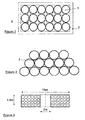
- the figure 1 shows in section a bundle of tubes (1) parallel enclosed in a chamber (2) for thermal insulation, environmental and / or safe.
- Additional heating of the air contained in horizontal straight tubes can be done from the inside or outside of the storage tube.
- FIG. 1 Another variant is to use a heat exchanger composed of pipes (3) arranged in the space available between the compressed air storage tubes.
- the tubes are preferably in metal-metal contact to facilitate the transfer of heat. by conduction.
- the figure 2 shows another arrangement of parallel tubes and heat exchange conduits (3).
- the heating or maintaining the temperature of the compressed air contained in the storage tube is obtained by the circulation of a hot fluid, steam or a coolant which exchanges, by thermal conductivity of the steel between the two types of tubes (compressed air tubes and hot fluid piping), heat with stored compressed air.
- Another embodiment of the storage of compressed gas consists in forming steel tube coils, preferably, but not necessarily, on the site itself given their size: dimensions of the coils, weight, and handling means available.
- the manufacture of the unitary coil can be obtained by winding, in plastic deformation of the steel tube, in successive layers on a drum with horizontal axis or vertical axis.
- the axis of the coil is vertical.
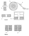
- a unitary storage coil with a maximum diameter of 15 m, a minimum diameter of 3 m and a width of 1.5 m, with a 6.625 "(16 cm) diameter tube, 6.4 mm thick, has a steel weight of 230 tonnes, one gas storage volume of 176 m 3, the volume of the cylinder constituted by such an elementary coil is 276 m 3 ( figure 3 ).
- the figure 4 schematically shows a coil with a horizontal axis (6) and a coil with a vertical axis (7).
- the coils are made from sections of 12-15m standard length steel tubes, assembled and welded to form a continuous tube which will then be bent in its plastic mode by means of pressure rollers (8) and wound on a specific drum. (9) to form an elementary coil, for example of volume 276 m 3 .
- each coil element can be fabricated on the spot, circled and then returned to move from a vertical coil (with its horizontal axis) to a horizontal coil (with its vertical axis), then positioned, lowered and placed flat at the bottom of the tank (10) ( figure 4 ) previously built.
- An excavation may be performed to contain the lower half of the drum to avoid a structure in height and facilitate the reeling of the continuous tube.
- a gantry compatible with the loads and dimensions of the coil (example: external diameter 15m, height 3m, weight of the coil 230 tons) will allow the tilting, its movement and the descent of the coil in the tank.
- the coil elements will thus be stacked on top of each other and connected by means of tubes with series or parallel connection.
- the tubes for storing compressed air may be contiguous (11) (contiguous turns) or slightly spaced (12) a few centimeters between each tube to facilitate the heat exchange between the steel of the coil. tube and the coolant if the air is stored warm ( figure 5 ).
Landscapes
- Engineering & Computer Science (AREA)
- Mechanical Engineering (AREA)
- General Engineering & Computer Science (AREA)
- Filling Or Discharging Of Gas Storage Vessels (AREA)
- Heat-Exchange Devices With Radiators And Conduit Assemblies (AREA)
Abstract
Description
- Le domaine de la présente invention concerne le stockage d'énergie par air comprimé (CAES pour "Compressed Air Energy Storage"). L'invention porte sur un système optimisé pour le stockage de l'air.
- Dans ce système, l'énergie, pouvant provenir d'électricité issue de sources renouvelables notamment, et que l'on souhaite utiliser à un autre moment, peut être stockée sous forme d'air comprimé. L'électricité produite en excès alimente donc un, ou plusieurs compresseurs dont le but est de comprimer une quantité d'air donnée et de la stocker dans des réservoirs adaptés.
- Il n'existe pas, à ce jour, de stockage local semi-massif d'air comprimé industriel, en réservoir artificiel (à la différence des stockages géologiques existants dans des cavités salines), entre 70 et 120 bars pour des volumes compris entre 1000m3 et 30 000m3 installés à terre, en surface ou sub-surface (ci-après désigné comme « mini CAES »).
- Ainsi, la présente invention concerne un système de stockage d'énergie sous forme d'air comprimé, caractérisé en ce qu'il est constitué par un assemblage de tubes aciers connectés pour former un volume de stockage disposé en surface, ou en sub-surface, ledit assemblage étant confiné dans une enveloppe isolante thermiquement.
- L'assemblage peut être constitué par des longueurs de tubes droits réunis en fagots et disposés en parallèle.
- L'assemblage peut être constitué par au moins un tube continu enroulé en bobine.
- Le volume de stockage peut comporter plusieurs assemblages confinés dans une enveloppe de protection environnementale et de sécurité.
- Le système peut comporter des moyens de chauffage ou de maintien de la chaleur de l'air comprimé stocké.
- Le volume de stockage peut être contenu dans une fosse aménagée dans le sol.
- La présente invention sera mieux comprise et ses avantages apparaîtront plus clairement à la lecture des modes de réalisations suivants, nullement limitatifs, et illustrés par les figures ci-après annexées, parmi lesquelles :
- la
figure 1 illustre schématiquement et en coupe, un assemblage de tubes aciers droits « en fagot » dans une enveloppe isolante, - la
figure 2 montre une disposition de conduites de chauffage et/ou de récupération de chaleur, - la
figure 3 illustre un exemple de dimensionnement de bobine de stockage selon l'invention, - la
figure 4 montre schématiquement les modes de réalisation de bobines à axe vertical et à axe horizontal et des dispositions d'assemblage de bobines. - la
figure 5 illustre le principe de bobine de stockage pour air comprimé à température ambiante ou à température de compression. - L'air à haute pression, par exemple entre 70 et 120 bars est stocké dans des tubes en acier, assemblés par soudures et disposés horizontalement en fagots en surface ou en semi-enterré pour bénéficier d'un milieu plus stable en température et/ou pour des raisons d'esthétiques, d'environnement et de sécurité. Les tubes en acier sont de préférence disposés horizontalement pour une plus grande facilité d'assemblage sur une plus grande longueur et pour diminuer le nombre de bouchons d'extrémité et de raccordements entre tubes.
- Pour réaliser ce système de stockage, il est possible d'utiliser des tubes pétroliers de type "sans soudure" (type tubage ou "casing" pétrolier) ou des tubes droits soudés avec soudures longitudinales ou en hélice utilisés pour les pipelines de gaz, dans la limite de leur pression de service.
- Ces tubes peuvent être protégés contre la corrosion en extérieur par des revêtements de polyoléfine, polyéthylène (PE), polypropylène (PP) et en intérieur par des revêtements époxy.
- Les tubes, en élément unitaire de 12-15 mètres sont assemblés et soudés préférentiellement sur le site de stockage, avec des moyens de manutention limités.
- Les longueurs peuvent atteindre, plusieurs dizaines de mètres en fonction du volume d'air souhaité et de la place sur le site de stockage. Les longueurs de tubes ainsi constitués sont disposées parallèles, puis mis en couches successives pour constituer un "fagot" de, par exemple, 10 par rangée et 10 en hauteur, soit pour atteindre une centaine de tubes.
- Les longueurs de tubes sont raccordées entre elles par des canalisations de diamètre approprié pour les mettre en communication, en parallèle ou en série, afin d'obtenir le volume de stockage choisi. Un jeu de vanne sur ces canalisations permet d'isoler une longueur, ou un ensemble de tubes.
- Le "fagot" constitué est de préférence quasi-horizontal, avec cependant une légère pente pour faciliter l'écoulement des condensats.
- Les tubes sont de préférence disposés horizontalement plutôt que verticalement. Horizontalement, ils permettent d'obtenir un plus important volume de stockage avec un minimum de conduites de raccordement et de bouchons aux extrémités des tubes, contrairement à la disposition verticale et partiellement enterrés, qui implique que la longueur de tube soit limitée à la profondeur de l'excavation. La multiplication des tubes verticaux augmente le nombre de bouchons d'extrémités, complique le raccordement, et augmente les couts de l'installation.
- Pour un tube de diamètre extérieur de 20" (0.508m) de diamètre intérieur 0.485m, longueur 10 m, fagot de 10 x 10 = 100 tubes. Le poids est de 137 tonnes pour un volume d'air comprimé de 185 m3, ce qui donne un ratio m3 d'air /poids acier de 1,348, ou le ratio de 0,742 tonnes d'acier/m3 stocké. Ce calcul ne prend pas en compte les embouts d'extrémités des tubes et les moyens de raccordements entre eux. Pour cette raison la règle de "un kilo d'acier pour un litre d'air comprimé stocké" peut être appliquée.
- Dans une variante selon l'invention, si l'air stocké est chaud (chaleur issue de la phase de compression), l'objectif est de conserver le plus longtemps possible la chaleur de l'air comprimé dans les tubes de stockage. Pour cela, la cuve contenant les fagots de tubes droits assemblés est thermiquement isolée du milieu extérieur pour conserver la chaleur de l'air comprimé introduit dans le stockage. La
figure 1 montre en coupe un fagot constitué de tubes (1) parallèles enfermés dans une enceinte (2) pour l'isolation thermique, environnementale et/ ou sécuritaire. - Un chauffage complémentaire de l'air, contenu dans des tubes droits horizontaux peut se faire par l'intérieur ou par l'extérieur du tube de stockage.
- Il y a la possibilité de disposer, dans chaque tube de stockage, un tube dit "insert" rempli d'un matériau de stockage de chaleur. Cependant avec ce système, il y aura une diminution du volume d'air stocké égale au volume des tubes de stockage de chaleur ou tubes de réchauffage.
- Une autre variante est d'utiliser un échangeur de chaleur composé de conduites (3) disposés dans l'espace disponible entre les tubes de stockage d'air comprimé, Les tubes sont de préférence en contact métal-métal pour faciliter le transfert de la chaleur par conduction. La
figure 2 montre une autre disposition des tubes parallèles et des conduites d'échange de chaleur (3). - Le chauffage ou le maintien en température de l'air comprimé contenu dans le tube de stockage est obtenu par la circulation d'un fluide chaud, de la vapeur ou un liquide caloporteur qui échange, par conductivité thermique de l'acier entre les deux types de tubes (tubes d'air comprimé et canalisation de fluide chaud), de la chaleur avec l'air comprimé stocké.
- Un autre mode de réalisation du stockage de gaz comprimé consiste à former des bobines de tubes en acier, de préférence, mais pas nécessairement, sur le site même compte tenu de leur encombrement: dimensions des bobines, poids, et des moyens de manutention disponibles.
- La fabrication de la bobine unitaire peut être obtenue par enroulement, en déformation plastique du tube en acier, en couches successives sur un touret à axe horizontal ou à axe vertical.
- De préférence, l'axe de la bobine est vertical.
- Une bobine unitaire de stockage de diamètre maximum 15 m, diamètre minimum 3m, de largeur 1,5m, avec un tube de diamètre 6.625" (16 cm), épaisseur 6,4 mm, a un poids d'acier de 230 tonnes, un volume de stockage de gaz de 176 m3. Le volume du cylindre constitué par une telle bobine élémentaire est de 276 m3 (
figure 3 ). - La
figure 4 montre schématiquement une bobine à axe horizontal (6) et une bobine à axe vertical (7). - Les bobines sont fabriquées à partir de tronçons de tubes standards en acier de longueur unitaire 12-15m, assemblés et soudés pour constituer un tube continu qui sera ensuite cintré dans son mode plastique au moyen de galets presseurs (8) et enroulé sur un touret spécifique (9) pour constituer une bobine élémentaire, par exemple de volume 276 m3.
- Plusieurs bobines unitaires peuvent être superposées puis interconnectées par des conduites pour constituer un volume de stockage dans une cuve (
figure 4 ). - La dimension de la bobine fabriquée et donc son poids est directement dépendant de la capacité de levage sur le site du mini CAES. Chaque élément de bobine peut être fabriquée sur place, cerclée puis retournée pour passer d'une bobine verticale (avec son axe horizontal) à une bobine horizontale (avec son axe vertical), puis positionnée, descendue et posée à plat au fond de la cuve (10) (
figure 4 ) préalablement construite. - Une excavation pourra être réalisée pour contenir la moitié basse du touret pour éviter une structure en hauteur et faciliter la mise en bobine du tube continu.
- Un portique compatible avec les charges et dimensions de la bobine (exemple: diamètre extérieur 15m, hauteur 3m, poids de la bobine 230 tonnes) permettra le basculement, son déplacement et la descente de la bobine dans la cuve.
- Il sera possible de fabriquer des éléments de bobine de hauteur plus réduite (par exemple 2 m) tout en conservant un diamètre extérieur acceptable (par exemple 15 m) pour maintenir le volume linéaire et pour réduire la masse de l'élément fabriqué.
- Les éléments de bobines seront ainsi empilées les unes sur les autres et raccordés au moyen de tubes avec mise en série ou parallèles.
- Les tubes de stockage de l'air comprimé peuvent être, à la construction de la bobine, jointifs (11) (spires jointives) ou légèrement espacés (12) de quelques centimètres entre chaque tubes pour faciliter les échanges de chaleur entre l'acier du tube et le fluide caloporteur si l'air est stocké chaud (
figure 5 ).
Claims (6)
- Système de stockage d'énergie sous forme d'air comprimé, caractérisé en ce qu'il est constitué par un assemblage de tubes aciers (1) connectés pour former un volume de stockage disposé en surface, ou en sub-surface, ledit assemblage étant confiné dans une enveloppe (2) isolante thermiquement.
- Système de stockage selon la revendication 1, dans lequel ledit assemblage est constitué par des longueurs de tubes droits réunis en fagots et disposés en parallèle.
- Système de stockage selon la revendication 1, dans lequel ledit assemblage est constitué par au moins un tube continu enroulé en bobine.
- Système de stockage selon l'une des revendications précédentes, dans lequel ledit volume de stockage comporte plusieurs assemblages confinés dans une enveloppe de protection environnementale et de sécurité.
- Système de stockage selon l'une des revendications précédentes, comportant des moyens de chauffage ou de maintien de la chaleur de l'air comprimé stocké.
- Système de stockage selon l'une des revendications précédentes, dans lequel ledit volume de stockage est contenu dans une fosse aménagée dans le sol.
Applications Claiming Priority (1)
| Application Number | Priority Date | Filing Date | Title |
|---|---|---|---|
| FR1362753A FR3014997A1 (fr) | 2013-12-17 | 2013-12-17 | Systeme de stockage d'energie sous forme d'air comprime dans un ensemble de tubes en surface |
Publications (2)
| Publication Number | Publication Date |
|---|---|
| EP2894386A2 true EP2894386A2 (fr) | 2015-07-15 |
| EP2894386A3 EP2894386A3 (fr) | 2015-12-30 |
Family
ID=50102106
Family Applications (1)
| Application Number | Title | Priority Date | Filing Date |
|---|---|---|---|
| EP14306886.4A Withdrawn EP2894386A3 (fr) | 2013-12-17 | 2014-11-26 | Systeme de stockage d'énergie sous forme d'air comprimé dans un ensemble de tubes en surface |
Country Status (3)
| Country | Link |
|---|---|
| US (1) | US20150167892A1 (fr) |
| EP (1) | EP2894386A3 (fr) |
| FR (1) | FR3014997A1 (fr) |
Families Citing this family (2)
| Publication number | Priority date | Publication date | Assignee | Title |
|---|---|---|---|---|
| CN115307053A (zh) * | 2022-08-18 | 2022-11-08 | 中科南京未来能源系统研究院 | 一种中空纤维管阵列储氢装置 |
| CN115325424B (zh) * | 2022-08-26 | 2024-02-09 | 国网江苏省电力有限公司电力科学研究院 | 一种储氢装置及其制作方法 |
Family Cites Families (14)
| Publication number | Priority date | Publication date | Assignee | Title |
|---|---|---|---|---|
| US2735658A (en) * | 1956-02-21 | Tubular surface heat exchanger | ||
| US4315408A (en) * | 1980-12-18 | 1982-02-16 | Amtel, Inc. | Offshore liquified gas transfer system |
| US5333465A (en) * | 1992-04-30 | 1994-08-02 | Mcbride Terry R | Underground storage system for natural gas |
| US5839383A (en) * | 1995-10-30 | 1998-11-24 | Enron Lng Development Corp. | Ship based gas transport system |
| US5725028A (en) * | 1996-05-13 | 1998-03-10 | Cleland; James M. | Trunk line |
| US6994104B2 (en) * | 2000-09-05 | 2006-02-07 | Enersea Transport, Llc | Modular system for storing gas cylinders |
| EP2160539B1 (fr) * | 2007-03-02 | 2017-05-03 | Enersea Transport LLC | Appareil et procédé permettant l'écoulement de fluides comprimés à l'intérieur et à l'extérieur d'une enceinte de confinement |
| US8136354B2 (en) * | 2008-03-14 | 2012-03-20 | Energy Compression Inc. | Adsorption-enhanced compressed air energy storage |
| EP2146125B1 (fr) * | 2008-07-17 | 2011-11-02 | Nexans | Conduite flexible |
| DE102010033956B4 (de) * | 2010-07-16 | 2012-11-08 | Thorben Meinardus | Druckgasspeichervorrichtung mit mindestens einem Druckgastank und mit einer Wärmeaufnahme- und/oder Wärmeübertragungsvorrichtung, insbesondere mit einem Wärmetauscher |
| DE102011107883A1 (de) * | 2011-07-18 | 2013-01-24 | Gaby Traute Reinhardt | Druck-Speichereinrichtung |
| US9255520B2 (en) * | 2012-02-27 | 2016-02-09 | Energy Compression Inc. | Modular adsorption-enhanced compressed air energy storage system with regenerative thermal energy recycling |
| US9217538B2 (en) * | 2012-05-03 | 2015-12-22 | Other Lab, Llc | Conformable natural gas storage |
| US20130336721A1 (en) * | 2012-06-13 | 2013-12-19 | Troy O. McBride | Fluid storage in compressed-gas energy storage and recovery systems |
-
2013
- 2013-12-17 FR FR1362753A patent/FR3014997A1/fr active Pending
-
2014
- 2014-11-26 EP EP14306886.4A patent/EP2894386A3/fr not_active Withdrawn
- 2014-12-15 US US14/570,101 patent/US20150167892A1/en not_active Abandoned
Non-Patent Citations (1)
| Title |
|---|
| None |
Also Published As
| Publication number | Publication date |
|---|---|
| EP2894386A3 (fr) | 2015-12-30 |
| FR3014997A1 (fr) | 2015-06-19 |
| US20150167892A1 (en) | 2015-06-18 |
Similar Documents
| Publication | Publication Date | Title |
|---|---|---|
| CN107250706B (zh) | 热能储存器和热交换器 | |
| EP2718652B1 (fr) | Accumulateur thermique, centrale d'accumulation thermique, procédé et utilisations de ceux-ci | |
| ES2864761T3 (es) | Medio de acumulación de energía térmica a alta temperatura, procedimiento de construcción y procedimiento de operación de dicho medio de acumulación | |
| ES2343035T3 (es) | Acumulador de calor para la acumulacion adiabatica de aire comprimido con fines de almacenamiento de energia. | |
| US7226243B2 (en) | Load-bearing, lightweight, and compact super-insulation system | |
| FR3024534A1 (fr) | Dispositif de stockage d'energie par materiau a changement de phase et un procede de stockage associe | |
| US20140124051A1 (en) | Heat transfer for heat pump water heater | |
| US20140116665A1 (en) | Method and apparatus for maintaining a minimum temperature in a fluid | |
| JP6148433B2 (ja) | 蓄熱及び放熱装置の容器、蓄熱及び放熱組立体、並びにエネルギー生産プラント | |
| FR3014997A1 (fr) | Systeme de stockage d'energie sous forme d'air comprime dans un ensemble de tubes en surface | |
| US10345051B1 (en) | Ground source heat pump heat exchanger | |
| CN103775820B (zh) | 一种新型带储热的超高压压缩空气蛇管储气器 | |
| FR3038376A1 (fr) | Dispositif de stockage d'energie par materiau a changement de phase et son procede de stockage | |
| EP3051079A1 (fr) | Systeme et procede de stockage d'energie sous forme d'air comprime dans des tubes integres dans une cuve contenant de l'eau et de la vapeur d'eau | |
| WO2012038620A1 (fr) | Dispositif d'accumulation et de restitution d'énergie | |
| US11022345B1 (en) | Ground source heat pump heat exchanger | |
| WO2020114836A1 (fr) | Reservoir de stockage d'un fluide sous pression avec une couche d'isolation thermique interne | |
| EP4720584A1 (fr) | Système géothermique comportant un système de production d'énergie | |
| EP2770288A1 (fr) | Système de stockage et de déstockage d'énergie thermique contenue dans un fluide | |
| FR2955647A1 (fr) | Capteur solaire a pression atmospherique autovidangeable utilisant des tubes solaires sous vide ouverts de chaque cote | |
| OA16681A (en) | Thermal energy storage and plant, method and use thereof. | |
| US20150260173A1 (en) | Thermal pumping via in situ pipes and apparatus including the same |
Legal Events
| Date | Code | Title | Description |
|---|---|---|---|
| PUAI | Public reference made under article 153(3) epc to a published international application that has entered the european phase |
Free format text: ORIGINAL CODE: 0009012 |
|
| 17P | Request for examination filed |
Effective date: 20141126 |
|
| AK | Designated contracting states |
Kind code of ref document: A2 Designated state(s): AL AT BE BG CH CY CZ DE DK EE ES FI FR GB GR HR HU IE IS IT LI LT LU LV MC MK MT NL NO PL PT RO RS SE SI SK SM TR |
|
| AX | Request for extension of the european patent |
Extension state: BA ME |
|
| PUAL | Search report despatched |
Free format text: ORIGINAL CODE: 0009013 |
|
| AK | Designated contracting states |
Kind code of ref document: A3 Designated state(s): AL AT BE BG CH CY CZ DE DK EE ES FI FR GB GR HR HU IE IS IT LI LT LU LV MC MK MT NL NO PL PT RO RS SE SI SK SM TR |
|
| AX | Request for extension of the european patent |
Extension state: BA ME |
|
| RIC1 | Information provided on ipc code assigned before grant |
Ipc: F17C 1/14 20060101AFI20151123BHEP Ipc: F17C 1/00 20060101ALI20151123BHEP |
|
| STAA | Information on the status of an ep patent application or granted ep patent |
Free format text: STATUS: THE APPLICATION IS DEEMED TO BE WITHDRAWN |
|
| 18D | Application deemed to be withdrawn |
Effective date: 20160701 |