EP2894298A1 - Fan assembly with fan blade under-root spacer - Google Patents
Fan assembly with fan blade under-root spacer Download PDFInfo
- Publication number
- EP2894298A1 EP2894298A1 EP15150185.5A EP15150185A EP2894298A1 EP 2894298 A1 EP2894298 A1 EP 2894298A1 EP 15150185 A EP15150185 A EP 15150185A EP 2894298 A1 EP2894298 A1 EP 2894298A1
- Authority
- EP
- European Patent Office
- Prior art keywords
- slot
- root
- base surface
- rotor
- outer periphery
- Prior art date
- Legal status (The legal status is an assumption and is not a legal conclusion. Google has not performed a legal analysis and makes no representation as to the accuracy of the status listed.)
- Withdrawn
Links
Images

Classifications
-
- F—MECHANICAL ENGINEERING; LIGHTING; HEATING; WEAPONS; BLASTING
- F04—POSITIVE - DISPLACEMENT MACHINES FOR LIQUIDS; PUMPS FOR LIQUIDS OR ELASTIC FLUIDS
- F04D—NON-POSITIVE-DISPLACEMENT PUMPS
- F04D29/00—Details, component parts, or accessories
- F04D29/26—Rotors specially for elastic fluids
- F04D29/32—Rotors specially for elastic fluids for axial flow pumps
- F04D29/321—Rotors specially for elastic fluids for axial flow pumps for axial flow compressors
- F04D29/322—Blade mountings
-
- F—MECHANICAL ENGINEERING; LIGHTING; HEATING; WEAPONS; BLASTING
- F01—MACHINES OR ENGINES IN GENERAL; ENGINE PLANTS IN GENERAL; STEAM ENGINES
- F01D—NON-POSITIVE DISPLACEMENT MACHINES OR ENGINES, e.g. STEAM TURBINES
- F01D5/00—Blades; Blade-carrying members; Heating, heat-insulating, cooling or antivibration means on the blades or the members
- F01D5/30—Fixing blades to rotors; Blade roots ; Blade spacers
- F01D5/32—Locking, e.g. by final locking blades or keys
- F01D5/323—Locking of axial insertion type blades by means of a key or the like parallel to the axis of the rotor
-
- F—MECHANICAL ENGINEERING; LIGHTING; HEATING; WEAPONS; BLASTING
- F05—INDEXING SCHEMES RELATING TO ENGINES OR PUMPS IN VARIOUS SUBCLASSES OF CLASSES F01-F04
- F05D—INDEXING SCHEME FOR ASPECTS RELATING TO NON-POSITIVE-DISPLACEMENT MACHINES OR ENGINES, GAS-TURBINES OR JET-PROPULSION PLANTS
- F05D2220/00—Application
- F05D2220/30—Application in turbines
- F05D2220/36—Application in turbines specially adapted for the fan of turbofan engines
-
- Y—GENERAL TAGGING OF NEW TECHNOLOGICAL DEVELOPMENTS; GENERAL TAGGING OF CROSS-SECTIONAL TECHNOLOGIES SPANNING OVER SEVERAL SECTIONS OF THE IPC; TECHNICAL SUBJECTS COVERED BY FORMER USPC CROSS-REFERENCE ART COLLECTIONS [XRACs] AND DIGESTS
- Y10—TECHNICAL SUBJECTS COVERED BY FORMER USPC
- Y10T—TECHNICAL SUBJECTS COVERED BY FORMER US CLASSIFICATION
- Y10T29/00—Metal working
- Y10T29/49—Method of mechanical manufacture
- Y10T29/49316—Impeller making
- Y10T29/4932—Turbomachine making
- Y10T29/49321—Assembling individual fluid flow interacting members, e.g., blades, vanes, buckets, on rotary support member
Definitions
- This disclosure relates to turbomachinery and, more particularly, to various means for holding a turbomachinery fan blade in a radially tight fashion within a supporting rotor slot.
- Turbomachinery fan blades may be secured to a supporting rotor by providing shaped slots in the rotor that mateably receive correspondingly shaped roots of the fan blades.
- the rotors may include dovetail or fir tree shaped slots that receive correspondingly shaped roots disposed at the radially inwardly ends of the fan blades.
- the slots of the rotor and the roots of the fan blades are adapted to lock the fan blades against radial movement as the rotor spins about its axis.
- interlocking blade shrouds may also be used to prevent excessive blade deflection and to dampen vibration.
- the combination of interlocking blade shrouds and a root/slot locking system for the fan blades and rotor can make it difficult or impossible to insert the fan blades in the slots of the rotor and/or to remove the fans blades from the rotor for service and/or replacement purposes.
- the slots may be oversized so that a fan blade may be moved radially inwardly a sufficient distance to permit the distal tip of the fan blade to clear the interlocking blade shrouds.
- spacers may be used to hold each blade radially tight within its respective slot. Such spacers may also facilitate balancing of the rotor and may prevent hammering and/or relative motion between abutting blade root and rotor surfaces, which may increase wear and therefore increase maintenance costs.
- spacers may be formed from a metallic material, which may cause galling during operation as the fan blade root and the rotor slot engage the metallic spacer. Further, metallic spacers may cause damage to the fan blade roots and/or the rotor slots during installation or removal of the fan blades from the rotor. Moreover, metallic spacers may be suitable for use only in closely toleranced rotor slots, thereby limiting their applicability.
- a fan assembly for turbomachinery may include a rotor having an outer periphery and at least one slot extending radially inwardly through the outer periphery of the rotor.
- the slot may terminate at a base surface disposed at a radial depth from the outer periphery of the rotor.
- the fan assembly may further include at least one fan blade including an airfoil connected to a root.
- the root maybe received in the slot.
- the root may terminate at an inner face.
- the root has a radial length that is less than the radial depth of the rotor slot to define a gap between the inner face of the root and the base surface of the slot when the root is biased away from the base surface of the slot.
- the fan assembly may further include a spacer disposed in the gap.
- the spacer may be fabricated from a polymer.
- a method of coupling a fan blade to a rotor may include providing a rotor that includes an outer periphery and at least one slot extending radially through the outer periphery before terminating at a base surface disposed at a radial depth from the outer periphery of the rotor.
- the method may further include providing at least one fan blade including an airfoil connected to a root.
- the root may terminate at an inner face and may have a radial length that is less than the radial depth of the slot.
- the method may further include providing a spacer fabricated from a polymer.
- the method may further include inserting the root of the fan blade into the slot of the rotor and moving the root and fan blade radially away from the base surface of the slot to expose a gap between the inner face of the root and the base surface of the slot.
- the method may further include inserting the spacer into the gap.
- a method of removing a fan blade from a rotor of a fan assembly may include providing a fan assembly that includes a rotor including an outer periphery and at least one slot extending radially through the outer periphery before terminating at a base surface disposed at a radial depth from the outer periphery of the rotor.
- the fan assembly may further include at least one fan blade including an airfoil connected to a root.
- the root maybe received in the slot of the rotor.
- the root may terminate at an inner face and the root may have a radial length that is less than the radial depth of the slot.
- the fan assembly may further include a spacer fabricated from a polymer and that is disposed between the base surface of the slot and the inner face of the root.
- the method may further include biasing the root radially outwardly away from the base surface of the slot, removing the spacer from between the inner face of the root and the base surface of the slot and removing the root from the slot.
- the polymer of the spacer may further include at least one reinforcing material.
- the reinforcing material may be selected from a group consisting of carbon fibers and glass fibers.
- the spacer may be injection-molded.
- the polymer may be selected from a group consisting of: polyetherimide (PEI), polyimide, polyether ether ketone (PEEK), polyether ketone ketone (PEKK), polysulfone, nylon, polyphenylsulfide, polyester, and combinations thereof.
- PEI polyetherimide
- PEEK polyether ether ketone
- PEKK polyether ketone ketone
- the slot may have a dovetail-shaped cross-sectional profile.
- the base surface of the rotor slot may be disposed between a pair of sidewalls that may extend from the base surface to the outer periphery of the rotor.
- the sidewalls may extend towards each other to form a throat disposed between the base surface and the outer periphery of the rotor.
- the base surface may have a width and the throat may also have a width.
- the inner face of the root may be disposed between two pressure faces. The inner face of the root may have a width that is smaller than the width of the base surface of the rotor slot and that is larger than the width of the throat of the rotor slot.
- the root of the fan blade and the slot of the rotor may be shaped so that the root is mateably received in the slot.
- FIG. 1 is a sectional view of a gas turbine engine 10.
- the gas turbine engine 10 may include a fan section 11 that, in turn, may include a fan blade assembly 12.
- the fan blade assembly 12 may be mounted immediately aft of a nose cone 13 and immediately fore of a low pressure compressor (LPC) 14.
- the LPC 14 may be part of a compressor section 15 and may be disposed between the fan blade assembly 12 and a high pressure compressor (HPC) 16.
- HPC 16 high pressure compressor
- the LPC 14 and HPC 16 may be disposed fore of a combustor 17, which may be disposed between the HPC 16 and a high pressure turbine (HPT) 18 that is part of a turbine section 19.
- the HPT 18 is typically disposed between the combustor 17 and a low pressure turbine (LPT) 21.
- the LPT 21 may be disposed immediately fore of a nozzle 22.
- the LPC 14 may be coupled to the LPT 21 via a shaft 23, which may extend through an annular shaft 24 that may couple the HPC 16 to the HPT 18.
- An engine case 25 may be disposed within an outer nacelle 26 that surrounds the fan section 11.
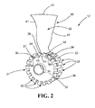
- the fan blade assembly 12 may include a plurality of fan blades 30 mounted to a rotor 31. More specifically, the rotor 31 may include an outer periphery 32 through which a plurality of dovetail shaped slots 33 extend.
- the slots 33 may include inner base surfaces 34.
- the base surfaces 34 may each be disposed between inwardly slanted sidewalls 36, 37 that extend inwardly towards each other as they extend radially outwardly from their respective base surfaces 34.
- the slots 33 may each accommodate a correspondingly shaped root 38 of a fan blade 30.
- the dovetail shaped root 38 may be connected to a blade 39 that includes a leading edge 41 and a trailing edge 42.
- the leading and trailing edges 41, 42 are disposed on either side of the blade tip 43.
- the root 38 may include an inner face 44 that may be disposed between and connected to inwardly slanted pressure faces 45, 46.
- the pressure faces 45, 46 may each engage the inwardly slanted sidewalls 36, 37 respectively of their respective slot 33 in the rotor 31.
- dovetail shaped slots 33 and roots 38 are shown herein, the reader will note that other types of slots and roots, including but not limited to fir tree shaped slots and correspondingly shaped roots are also clearly applicable to this disclosure and are considered within the scope of this disclosure.
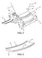
- each slot 33 extends radially inwardly through the outer periphery 32 of the rotor 31.
- Each slot 33 terminates at a base surface 34 that is disposed at a radial depth R 1 from the outer periphery 32.
- the base surface 34 is disposed between and is connected to a pair of sidewalls 36, 37.
- the sidewall 36, 37 extend from the base surface 34 to the outer periphery 32 and extend towards each other to form a throat at or below the outer periphery 32.
- the throat has a width W 1 as illustrated in FIG. 3 .
- the width W 1 is less than the width W 2 of the base surface 34 as illustrated in FIG. 3 .
- the slot 33 may have a dovetail-shaped cross-sectional profile. As indicated above, other profiles, such as fir tree, T-shaped, etc. may be employed.
- the root 38 of the fan blade 30 also has a dovetail-shaped cross-sectional profile. Specifically, the root 38 extends radially inwardly before terminating at an inner face 44 that has a radial distance R 2 .
- the radial distance R 2 ( FIG. 5 ) is less than the radial depth R 1 of each slot 33 ( FIG. 3 ).
- the inner face 44 of the root 38 has a width W 3 that is less than the width W 1 of the throat of each slot.
- the root 38 may have a complementary dovetail-shaped cross-sectional profile that matches the profile of the slots 33.
- the inner face 44 of the root 38 is disposed between and connected to the pair of inwardly slanted pressure faces 45, 46.
- the pressure faces 45, 46 engage the throat of the slot 33, which prevents the fan blade 30 from disengaging from rotor 31.
- a gap 50 exists between the inner face 44 of the root 38 and the base surface 34 of the slot 33 as illustrated in FIG.3 .
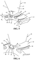
- a spacer 51 may be inserted into the gap 50 as illustrated in FIGS. 5 and 6 .
- the spacer 51 in addition to holding the blade 30 radially tight within the slot 33 may also facilitate balancing of the rotor 31 and may further prevent hammering and/or relative motion between the pressure faces 45, 46 of the root 38 and the side walls 36, 37 of the slot 33.
- FIG. 4 A perspective view of the spacer 51 is illustrated in FIG. 4 .
- the spacer 51 may have a thickness that is slightly less than or about equal to the thickness of the gap 50 illustrated in FIG. 3 .
- Tapered side walls 52, 53 surround the inner face 44 of the root 38 and enhance the ability of spacer 51 to prevent hammering and relative motion of the fan blade 30 within the slot 33.
- the upper surface 54 engages the inner face 44 of the root 38 while the bottom surface 55 engages the base surface 34 of the slot 33. Because the spacer 51 is fabricated from a polymeric material, it has a lower coefficient of friction than typical metallic materials used to fabricate such spacers and may be easier to insert into the gap 50 than conventional metal spacers. Further, by using a polymeric material, weight savings and cost savings are also achieved.
- An exemplary substrate for use in fabricating the spacer 51 is an injection-molded, compression-molded, blow-molded, additively manufactured or a composite-layup piece formed of at least one of the following: polyamide, polyetherimide (PEI), polyimide, polyether ether ketone (PEEK), polyether ketone ketone (PEKK), polysulfone, nylon, polyphenylsulfide, polyester, or any of the foregoing with fiber reinforcement e.g., carbon fiber or glass-fiber.
- PEI polyetherimide
- PEEK polyether ether ketone
- PEKK polyether ketone ketone
- polysulfone nylon, polyphenylsulfide, polyester, or any of the foregoing with fiber reinforcement e.g., carbon fiber or glass-fiber.
- the spacer 51 may be fabricated from a polymer, it may provide a substantial reduction in cost versus a metallic spacer. For example, typical metallic spacers must be machined and, depending upon the specific material used, can cost several hundred dollars. In contrast, an injection molded polymeric spacer may cost substantially less than a hundred dollars.
- the disclosed spacers 51 also are substantially lighter than metallic spacers.
- the composite materials listed above have a density of about 1/3 of the density of titanium and about 1/2 of the density of aluminum, which are both common metal spacer materials.
Landscapes
- Engineering & Computer Science (AREA)
- Mechanical Engineering (AREA)
- General Engineering & Computer Science (AREA)
- Structures Of Non-Positive Displacement Pumps (AREA)
Abstract
Description
- This disclosure relates to turbomachinery and, more particularly, to various means for holding a turbomachinery fan blade in a radially tight fashion within a supporting rotor slot.
- Turbomachinery fan blades may be secured to a supporting rotor by providing shaped slots in the rotor that mateably receive correspondingly shaped roots of the fan blades. For example, the rotors may include dovetail or fir tree shaped slots that receive correspondingly shaped roots disposed at the radially inwardly ends of the fan blades. The slots of the rotor and the roots of the fan blades are adapted to lock the fan blades against radial movement as the rotor spins about its axis.
- However, for large fan blades, such as high bypass ratio fan blades, interlocking blade shrouds may also be used to prevent excessive blade deflection and to dampen vibration. The combination of interlocking blade shrouds and a root/slot locking system for the fan blades and rotor can make it difficult or impossible to insert the fan blades in the slots of the rotor and/or to remove the fans blades from the rotor for service and/or replacement purposes. To facilitate removal and replacement of a shrouded and locked fan blade from a fully assembled rotor, the slots may be oversized so that a fan blade may be moved radially inwardly a sufficient distance to permit the distal tip of the fan blade to clear the interlocking blade shrouds.
- Where such radially oversized slots are utilized, spacers may be used to hold each blade radially tight within its respective slot. Such spacers may also facilitate balancing of the rotor and may prevent hammering and/or relative motion between abutting blade root and rotor surfaces, which may increase wear and therefore increase maintenance costs.
- Typically, such spacers may be formed from a metallic material, which may cause galling during operation as the fan blade root and the rotor slot engage the metallic spacer. Further, metallic spacers may cause damage to the fan blade roots and/or the rotor slots during installation or removal of the fan blades from the rotor. Moreover, metallic spacers may be suitable for use only in closely toleranced rotor slots, thereby limiting their applicability.
- In one aspect, a fan assembly for turbomachinery is disclosed. The disclosed fan assembly may include a rotor having an outer periphery and at least one slot extending radially inwardly through the outer periphery of the rotor. The slot may terminate at a base surface disposed at a radial depth from the outer periphery of the rotor. The fan assembly may further include at least one fan blade including an airfoil connected to a root. The root maybe received in the slot. The root may terminate at an inner face. The root has a radial length that is less than the radial depth of the rotor slot to define a gap between the inner face of the root and the base surface of the slot when the root is biased away from the base surface of the slot. The fan assembly may further include a spacer disposed in the gap. The spacer may be fabricated from a polymer.
- In another aspect, a method of coupling a fan blade to a rotor is disclosed. The method may include providing a rotor that includes an outer periphery and at least one slot extending radially through the outer periphery before terminating at a base surface disposed at a radial depth from the outer periphery of the rotor. The method may further include providing at least one fan blade including an airfoil connected to a root. The root may terminate at an inner face and may have a radial length that is less than the radial depth of the slot. The method may further include providing a spacer fabricated from a polymer. The method may further include inserting the root of the fan blade into the slot of the rotor and moving the root and fan blade radially away from the base surface of the slot to expose a gap between the inner face of the root and the base surface of the slot. The method may further include inserting the spacer into the gap.
- In another aspect, a method of removing a fan blade from a rotor of a fan assembly is disclosed. The method may include providing a fan assembly that includes a rotor including an outer periphery and at least one slot extending radially through the outer periphery before terminating at a base surface disposed at a radial depth from the outer periphery of the rotor. The fan assembly may further include at least one fan blade including an airfoil connected to a root. The root maybe received in the slot of the rotor. The root may terminate at an inner face and the root may have a radial length that is less than the radial depth of the slot. The fan assembly may further include a spacer fabricated from a polymer and that is disposed between the base surface of the slot and the inner face of the root. The method may further include biasing the root radially outwardly away from the base surface of the slot, removing the spacer from between the inner face of the root and the base surface of the slot and removing the root from the slot.
- In any one or more of the embodiments described above, the polymer of the spacer may further include at least one reinforcing material.
- In any one or more of the embodiments described above, the reinforcing material may be selected from a group consisting of carbon fibers and glass fibers.
- In any one or more of the embodiments described above, the spacer may be injection-molded.
- In any one or more of the embodiments described above, the polymer may be selected from a group consisting of: polyetherimide (PEI), polyimide, polyether ether ketone (PEEK), polyether ketone ketone (PEKK), polysulfone, nylon, polyphenylsulfide, polyester, and combinations thereof.
- In any one or more of the embodiments described above, the slot may have a dovetail-shaped cross-sectional profile.
- In any one or more of the embodiments described above, the base surface of the rotor slot may be disposed between a pair of sidewalls that may extend from the base surface to the outer periphery of the rotor. The sidewalls may extend towards each other to form a throat disposed between the base surface and the outer periphery of the rotor. The base surface may have a width and the throat may also have a width. Further, the inner face of the root may be disposed between two pressure faces. The inner face of the root may have a width that is smaller than the width of the base surface of the rotor slot and that is larger than the width of the throat of the rotor slot.
- In any one or more of the embodiments described above, the root of the fan blade and the slot of the rotor may be shaped so that the root is mateably received in the slot.
- Other advantages and features will be apparent from the following detailed description when read in conjunction with the attached drawings.
- For a more complete understanding of the disclosed methods and apparatuses, reference should be made to the embodiment illustrated in greater detail on the accompanying drawings, wherein:
-
FIG. 1 is a sectional view of a gas turbine engine; -
FIG. 2 is a perspective view of a rotor and fan blade that forms one part of the fan assembly of the gas turbine engine illustrated inFIG. 1 . -
FIG. 3 is a partial perspective view of the rotor and fan blade shown inFIG. 2 and with a disclosed spacer that maybe received in the gap between the root of the fan blade and the base surface of the slot of the rotor. -
FIG. 4 is a perspective view of the spacer illustrated inFIG. 3 . -
FIG. 5 is another partial perspective view of the rotor and fan blade but with the spacer disposed in the gap between the inner face of the root of the fan blade and the base surface of the slot of the rotor. -
FIG. 6 is an enlarged partial perspective view of the fan blade, rotor and spacer as illustrated inFIG. 5 . - It should be understood that the drawings are not necessarily to scale and that the disclosed embodiments are sometimes illustrated diagrammatically and in partial views. In certain instances, details which are not necessary for an understanding of the disclosed methods and apparatuses or which render other details difficult to perceive may have been omitted. It should be understood, of course, that this disclosure is not limited to the particular embodiments illustrated herein.
-
FIG. 1 is a sectional view of agas turbine engine 10. Thegas turbine engine 10 may include afan section 11 that, in turn, may include afan blade assembly 12. Thefan blade assembly 12 may be mounted immediately aft of anose cone 13 and immediately fore of a low pressure compressor (LPC) 14. TheLPC 14 may be part of acompressor section 15 and may be disposed between thefan blade assembly 12 and a high pressure compressor (HPC) 16. TheLPC 14 andHPC 16 may be disposed fore of acombustor 17, which may be disposed between theHPC 16 and a high pressure turbine (HPT) 18 that is part of aturbine section 19. TheHPT 18 is typically disposed between the combustor 17 and a low pressure turbine (LPT) 21. TheLPT 21 may be disposed immediately fore of anozzle 22. TheLPC 14 may be coupled to theLPT 21 via ashaft 23, which may extend through anannular shaft 24 that may couple theHPC 16 to theHPT 18. Anengine case 25 may be disposed within anouter nacelle 26 that surrounds thefan section 11. - Turning to
FIG. 2 , thefan blade assembly 12 may include a plurality offan blades 30 mounted to arotor 31. More specifically, therotor 31 may include anouter periphery 32 through which a plurality of dovetail shapedslots 33 extend. Theslots 33 may include inner base surfaces 34. The base surfaces 34 may each be disposed between inwardly slantedsidewalls FIG. 2 , theslots 33 may each accommodate a correspondingly shapedroot 38 of afan blade 30. The dovetail shapedroot 38 may be connected to ablade 39 that includes aleading edge 41 and a trailingedge 42. The leading and trailingedges blade tip 43. - As shown in
FIGS. 2-3 and5-6 , theroot 38 may include aninner face 44 that may be disposed between and connected to inwardly slanted pressure faces 45, 46. The pressure faces 45, 46 may each engage the inwardly slantedsidewalls respective slot 33 in therotor 31. - While dovetail shaped
slots 33 androots 38 are shown herein, the reader will note that other types of slots and roots, including but not limited to fir tree shaped slots and correspondingly shaped roots are also clearly applicable to this disclosure and are considered within the scope of this disclosure. - Turning to
FIG. 3 , as described above, eachslot 33 extends radially inwardly through theouter periphery 32 of therotor 31. Eachslot 33 terminates at abase surface 34 that is disposed at a radial depth R1 from theouter periphery 32. Thebase surface 34 is disposed between and is connected to a pair ofsidewalls sidewall base surface 34 to theouter periphery 32 and extend towards each other to form a throat at or below theouter periphery 32. The throat has a width W1 as illustrated inFIG. 3 . The width W1 is less than the width W2 of thebase surface 34 as illustrated inFIG. 3 . In other words, theslot 33 may have a dovetail-shaped cross-sectional profile. As indicated above, other profiles, such as fir tree, T-shaped, etc. may be employed. - Turning to
FIG. 5 , theroot 38 of thefan blade 30 also has a dovetail-shaped cross-sectional profile. Specifically, theroot 38 extends radially inwardly before terminating at aninner face 44 that has a radial distance R2. The radial distance R2 (FIG. 5 ) is less than the radial depth R1 of each slot 33 (FIG. 3 ). Further, referring back toFIG. 5 , theinner face 44 of theroot 38 has a width W3 that is less than the width W1 of the throat of each slot. In other words, theroot 38 may have a complementary dovetail-shaped cross-sectional profile that matches the profile of theslots 33. Specifically, theinner face 44 of theroot 38 is disposed between and connected to the pair of inwardly slanted pressure faces 45, 46. When thefan blade 30 is biased in a radially outwardly direction, the pressure faces 45, 46 engage the throat of theslot 33, which prevents thefan blade 30 from disengaging fromrotor 31. Once thefan blade 30 is biased in a radially outwardly direction, a gap 50 exists between theinner face 44 of theroot 38 and thebase surface 34 of theslot 33 as illustrated inFIG.3 . To hold thefan blade 30 tight within theslot 33, aspacer 51 may be inserted into the gap 50 as illustrated inFIGS. 5 and 6 . Thespacer 51, in addition to holding theblade 30 radially tight within theslot 33 may also facilitate balancing of therotor 31 and may further prevent hammering and/or relative motion between the pressure faces 45, 46 of theroot 38 and theside walls slot 33. - A perspective view of the
spacer 51 is illustrated inFIG. 4 . Thespacer 51 may have a thickness that is slightly less than or about equal to the thickness of the gap 50 illustrated inFIG. 3 .Tapered side walls inner face 44 of theroot 38 and enhance the ability ofspacer 51 to prevent hammering and relative motion of thefan blade 30 within theslot 33. Theupper surface 54 engages theinner face 44 of theroot 38 while thebottom surface 55 engages thebase surface 34 of theslot 33. Because thespacer 51 is fabricated from a polymeric material, it has a lower coefficient of friction than typical metallic materials used to fabricate such spacers and may be easier to insert into the gap 50 than conventional metal spacers. Further, by using a polymeric material, weight savings and cost savings are also achieved. - An exemplary substrate for use in fabricating the
spacer 51 is an injection-molded, compression-molded, blow-molded, additively manufactured or a composite-layup piece formed of at least one of the following: polyamide, polyetherimide (PEI), polyimide, polyether ether ketone (PEEK), polyether ketone ketone (PEKK), polysulfone, nylon, polyphenylsulfide, polyester, or any of the foregoing with fiber reinforcement e.g., carbon fiber or glass-fiber. - Because the
spacer 51 may be fabricated from a polymer, it may provide a substantial reduction in cost versus a metallic spacer. For example, typical metallic spacers must be machined and, depending upon the specific material used, can cost several hundred dollars. In contrast, an injection molded polymeric spacer may cost substantially less than a hundred dollars. The disclosedspacers 51 also are substantially lighter than metallic spacers. For example, the composite materials listed above have a density of about 1/3 of the density of titanium and about 1/2 of the density of aluminum, which are both common metal spacer materials. - While only certain embodiments have been set forth, alternative embodiments and various modifications will be apparent from the above description to those skilled on the art. These and other alternatives are considered equivalents in within the scope of this disclosure.
Claims (15)
- A fan assembly (12) comprising:a rotor (31) having an outer periphery (32) and at least one slot (33) extending radially inwardly through the outer periphery (32) and terminating at a base surface (34) disposed at a radial depth (R1) from the outer periphery (32) of the rotor (31);at least one fan blade (30) including an airfoil (39) connected to a root (38), the root (38) being received in the slot (33), the root (38) terminating at an inner face (44) and having a radial length (R2) that is less than the radial depth (R1) of the slot (33) to define a gap (50) between the inner face (44) of the root (38) and the base surface (34) of the slot (33); anda spacer (51) disposed in the gap (50), the spacer (51) being fabricated from a polymer.
- The fan assembly (12) of claim 1, wherein the polymer is embedded with at least one reinforcing material.
- The fan assembly (12) of claim 2, wherein the reinforcing material comprises carbon fibers and/or glass fibers.
- The fan assembly (12) of any of claims 1 to 3, wherein the spacer (51) is injection-molded.
- The fan assembly (12) of any preceding claim, wherein the polymer comprises polyamide, polyetherimide (PEI), polyimide, polyether ether ketone (PEEK), polyether ketone ketone (PEKK), polysulfone, nylon, polyphenylsulfide, polyester, or combinations thereof.
- The fan assembly (12) of any preceding claim, wherein the slot (33) has a dovetail-shaped cross-sectional profile.
- The fan assembly (12) of any preceding claim, wherein the base surface (34) is disposed between a pair of sidewalls (36,37) that extend from the base surface (34) to the outer periphery (32) of the rotor (31), the sidewalls (36,37) extending towards each other to form a throat disposed between the base surface (33) and the outer periphery (32) of the rotor (31), the base surface (33) having a width (W2) and the throat having a width (W1) and the inner face (44) of the root (38) being disposed between two pressure faces (45,46), the inner face (44) having a width (W3) that is smaller than the width (W2) of the base surface (33) and that is larger than the width (W1) of the throat.
- The fan assembly (12) of any preceding claim, wherein the root (38) and slot (33) are shaped so that the root (38) is mateably received in the slot (33).
- A method of coupling a fan blade (30) to a rotor (31), the method comprising:providing a rotor (31) including an outer periphery (32) and at least one slot (33) extending radially through the outer periphery (32) before terminating at a base surface (34) disposed at a radial depth (R1) from the outer periphery (32);providing at least one fan blade (30) including an airfoil (39) connected to a root (38), the root (38) terminating at an inner face (44) and having a radial length (R2) that is less than the radial depth (R1) of the slot (33);providing a spacer (51) fabricated from a polymer;inserting the root (38) of the fan blade (30) into the slot (33) of the rotor (31);moving the root (38) radially outwardly away from the base surface (34) of the slot (33) to expose a gap (50) between the inner face (44) of the root (38) and the base surface (34) of the slot (33); andinserting the spacer (51) into the gap (50).
- The method of claim 9, wherein the polymer is embedded with at least one reinforcing material, and optionally wherein the reinforcing material is selected from the group consisting of carbon fibers and glass fibers.
- The method of claim 9 or 10, wherein the spacer (51) is injection-molded.
- The method of any of claims 9 to 11, wherein the polymer comprises polyamide, polyetherimide (PEI), polyimide, polyether ether ketone (PEEK), polyether ketone ketone (PEKK), polysulfone, nylon, polyphenylsulfide, polyester, and/or combinations thereof.
- The method of any of claims 9 to 12, wherein the slot (33) has a dovetail-shaped cross-sectional profile.
- The method of any of claims 9 to 13, wherein the base surface (34) of the slot (33) is disposed between a pair of sidewalls (36,37) that extend from the base surface (34) to the outer periphery (32), the sidewalls (36,37) extending towards each other to form a throat disposed between the base surface (34) and the outer periphery (32), the base surface (34) having a width (W2) and the throat having a width (W1), the inner face (44) of the root (38) is disposed between two pressure faces (45,46), the inner face (44) having a width (W3) that is smaller than the width (W2) of the base surface (34) and that is larger than the width (W1) of the throat, and the moving of the fan blade (30) radially outward away from the base surface (34) includes moving of the fan blade (30) radially outward away from the base surface (34) until the two pressure faces (45,46) of the root (38) engage the throat of the slot (33).
- The fan assembly of any of claims 1 to 8, wherein the gap (50) is defined between the inner face (44) of the root (38) and the base surface (34) of the slot (33) when the root (38) is biased away from the base surface (34) of the slot (33).
Applications Claiming Priority (1)
| Application Number | Priority Date | Filing Date | Title |
|---|---|---|---|
| US201461924892P | 2014-01-08 | 2014-01-08 |
Publications (1)
| Publication Number | Publication Date |
|---|---|
| EP2894298A1 true EP2894298A1 (en) | 2015-07-15 |
Family
ID=52338980
Family Applications (1)
| Application Number | Title | Priority Date | Filing Date |
|---|---|---|---|
| EP15150185.5A Withdrawn EP2894298A1 (en) | 2014-01-08 | 2015-01-06 | Fan assembly with fan blade under-root spacer |
Country Status (2)
| Country | Link |
|---|---|
| US (1) | US20150192144A1 (en) |
| EP (1) | EP2894298A1 (en) |
Families Citing this family (6)
| Publication number | Priority date | Publication date | Assignee | Title |
|---|---|---|---|---|
| GB2546298B (en) * | 2016-01-14 | 2022-06-15 | Advanced Electric Machines Group Ltd | Rotor assembly |
| US10436224B2 (en) * | 2016-04-01 | 2019-10-08 | General Electric Company | Method and apparatus for balancing a rotor |
| US10527002B2 (en) * | 2016-06-17 | 2020-01-07 | Rohr, Inc. | Coated thermoplastic seal retainer for fire seal test |
| GB201819413D0 (en) | 2018-11-29 | 2019-01-16 | Rolls Royce Plc | Geared turbofan engine |
| GB201819412D0 (en) * | 2018-11-29 | 2019-01-16 | Rolls Royce Plc | Geared turbofan engine |
| CN109630465A (en) * | 2018-12-16 | 2019-04-16 | 中国航发沈阳发动机研究所 | A kind of fan gasket |
Citations (4)
| Publication number | Priority date | Publication date | Assignee | Title |
|---|---|---|---|---|
| US20100189564A1 (en) * | 2009-01-23 | 2010-07-29 | Paul Stone | Blade preloading system and method |
| US20120107125A1 (en) * | 2009-04-29 | 2012-05-03 | Snecma | Reinforced fan blade shim |
| US20130156591A1 (en) * | 2011-12-16 | 2013-06-20 | United Technologies Corporation | Energy absorbent fan blade spacer |
| WO2015053922A1 (en) * | 2013-10-11 | 2015-04-16 | United Technologies Corporation | Compressible fan blade with root spacer |
Family Cites Families (5)
| Publication number | Priority date | Publication date | Assignee | Title |
|---|---|---|---|---|
| US6692231B1 (en) * | 2001-02-28 | 2004-02-17 | General Shelters Of Texas S.B., Ltd. | Molded fan having repositionable blades |
| FR2918703B1 (en) * | 2007-07-13 | 2009-10-16 | Snecma Sa | ROTOR ASSEMBLY OF TURBOMACHINE |
| FR2918702B1 (en) * | 2007-07-13 | 2009-10-16 | Snecma Sa | CLINKING FOR TURBOMACHINE BLADE |
| FR2921099B1 (en) * | 2007-09-13 | 2013-12-06 | Snecma | DAMPING DEVICE FOR DRAWINGS OF COMPOSITE MATERIAL |
| US20150322805A1 (en) * | 2012-12-27 | 2015-11-12 | United Technologies Corporation | Blade underroot spacer with hook removal |
-
2014
- 2014-10-07 US US14/508,774 patent/US20150192144A1/en not_active Abandoned
-
2015
- 2015-01-06 EP EP15150185.5A patent/EP2894298A1/en not_active Withdrawn
Patent Citations (4)
| Publication number | Priority date | Publication date | Assignee | Title |
|---|---|---|---|---|
| US20100189564A1 (en) * | 2009-01-23 | 2010-07-29 | Paul Stone | Blade preloading system and method |
| US20120107125A1 (en) * | 2009-04-29 | 2012-05-03 | Snecma | Reinforced fan blade shim |
| US20130156591A1 (en) * | 2011-12-16 | 2013-06-20 | United Technologies Corporation | Energy absorbent fan blade spacer |
| WO2015053922A1 (en) * | 2013-10-11 | 2015-04-16 | United Technologies Corporation | Compressible fan blade with root spacer |
Also Published As
| Publication number | Publication date |
|---|---|
| US20150192144A1 (en) | 2015-07-09 |
Similar Documents
| Publication | Publication Date | Title |
|---|---|---|
| EP2894298A1 (en) | Fan assembly with fan blade under-root spacer | |
| US9097125B2 (en) | Intentionally frequency mistuned turbine blades | |
| EP2896791B1 (en) | Mistuned airfoil assemblies | |
| US8186961B2 (en) | Blade preloading system | |
| EP2372096B1 (en) | Composite fan blade dovetail root | |
| EP2971552B1 (en) | Injection molded composite fan platform | |
| US8277188B2 (en) | Turbomachine rotor disk | |
| EP1288440B1 (en) | Dovetail blade root and rotor groove configuration | |
| JP6302479B2 (en) | Device with engineering surface features and corresponding method for reducing wear and friction in CMC-metal attachments | |
| EP3208467B1 (en) | Compressor rotor for supersonic flutter and/or resonant stress mitigation | |
| EP2093378A1 (en) | Upgrading method for a blade by retrofitting a winglet, and correspondingly upgraded blade | |
| US20090297351A1 (en) | Compressor rotor blade undercut | |
| WO2013130570A1 (en) | Turbine engine rotor blade groove | |
| CN102606222A (en) | Axial retention device for turbine system | |
| US7153102B2 (en) | Bladed disk fixing undercut | |
| US11795825B2 (en) | Inter-blade platform with a sacrificial box section | |
| US9739159B2 (en) | Method and system for relieving turbine rotor blade dovetail stress | |
| EP2233696A2 (en) | Turbomachine rotor assembly and method | |
| EP1762704B1 (en) | Vane assembly with grommet | |
| US11073031B2 (en) | Blade for a gas turbine engine | |
| US20070177979A1 (en) | Vane comprising a transition zone | |
| EP3009609A1 (en) | Mounting arrangement for variable stator vane | |
| EP2672067A1 (en) | Turbine rotor and blade assembly with blind holes and corresponding steam turbine | |
| EP2672068B1 (en) | Turbine rotor and blade assembly with multi-piece locking blade | |
| EP2910737A1 (en) | A rotor for a turbo-machine and a related method |
Legal Events
| Date | Code | Title | Description |
|---|---|---|---|
| PUAI | Public reference made under article 153(3) epc to a published international application that has entered the european phase |
Free format text: ORIGINAL CODE: 0009012 |
|
| 17P | Request for examination filed |
Effective date: 20150106 |
|
| AK | Designated contracting states |
Kind code of ref document: A1 Designated state(s): AL AT BE BG CH CY CZ DE DK EE ES FI FR GB GR HR HU IE IS IT LI LT LU LV MC MK MT NL NO PL PT RO RS SE SI SK SM TR |
|
| AX | Request for extension of the european patent |
Extension state: BA ME |
|
| R17P | Request for examination filed (corrected) |
Effective date: 20160115 |
|
| RBV | Designated contracting states (corrected) |
Designated state(s): AL AT BE BG CH CY CZ DE DK EE ES FI FR GB GR HR HU IE IS IT LI LT LU LV MC MK MT NL NO PL PT RO RS SE SI SK SM TR |
|
| RAP1 | Party data changed (applicant data changed or rights of an application transferred) |
Owner name: UNITED TECHNOLOGIES CORPORATION |
|
| STAA | Information on the status of an ep patent application or granted ep patent |
Free format text: STATUS: EXAMINATION IS IN PROGRESS |
|
| 17Q | First examination report despatched |
Effective date: 20180618 |
|
| RAP1 | Party data changed (applicant data changed or rights of an application transferred) |
Owner name: RAYTHEON TECHNOLOGIES CORPORATION |
|
| STAA | Information on the status of an ep patent application or granted ep patent |
Free format text: STATUS: THE APPLICATION IS DEEMED TO BE WITHDRAWN |
|
| 18D | Application deemed to be withdrawn |
Effective date: 20210225 |