EP2894293A2 - Cutting pick tool - Google Patents
Cutting pick tool Download PDFInfo
- Publication number
- EP2894293A2 EP2894293A2 EP14154696.0A EP14154696A EP2894293A2 EP 2894293 A2 EP2894293 A2 EP 2894293A2 EP 14154696 A EP14154696 A EP 14154696A EP 2894293 A2 EP2894293 A2 EP 2894293A2
- Authority
- EP
- European Patent Office
- Prior art keywords
- tip
- tool
- support body
- recess
- region
- Prior art date
- Legal status (The legal status is an assumption and is not a legal conclusion. Google has not performed a legal analysis and makes no representation as to the accuracy of the status listed.)
- Withdrawn
Links
- 238000005520 cutting process Methods 0.000 title claims abstract description 63
- 239000002131 composite material Substances 0.000 claims abstract description 20
- 229910003460 diamond Inorganic materials 0.000 claims abstract description 18
- 239000010432 diamond Substances 0.000 claims abstract description 18
- 230000000295 complement effect Effects 0.000 claims abstract description 8
- 229910000831 Steel Inorganic materials 0.000 claims description 18
- 230000004323 axial length Effects 0.000 claims description 18
- 239000010959 steel Substances 0.000 claims description 18
- 238000000034 method Methods 0.000 claims description 11
- 238000005219 brazing Methods 0.000 claims description 10
- 238000004519 manufacturing process Methods 0.000 claims description 4
- 230000007704 transition Effects 0.000 claims description 3
- 239000000463 material Substances 0.000 description 11
- 239000011435 rock Substances 0.000 description 7
- 239000011159 matrix material Substances 0.000 description 4
- 239000007769 metal material Substances 0.000 description 4
- XUIMIQQOPSSXEZ-UHFFFAOYSA-N Silicon Chemical compound [Si] XUIMIQQOPSSXEZ-UHFFFAOYSA-N 0.000 description 3
- 239000011230 binding agent Substances 0.000 description 3
- 239000002245 particle Substances 0.000 description 3
- 229910052710 silicon Inorganic materials 0.000 description 3
- 239000010703 silicon Substances 0.000 description 3
- 230000003313 weakening effect Effects 0.000 description 3
- 230000008878 coupling Effects 0.000 description 2
- 238000010168 coupling process Methods 0.000 description 2
- 238000005859 coupling reaction Methods 0.000 description 2
- 239000002184 metal Substances 0.000 description 2
- 229910052751 metal Inorganic materials 0.000 description 2
- 238000005065 mining Methods 0.000 description 2
- 238000009412 basement excavation Methods 0.000 description 1
- 230000009286 beneficial effect Effects 0.000 description 1
- 230000015572 biosynthetic process Effects 0.000 description 1
- 238000010276 construction Methods 0.000 description 1
- 238000005553 drilling Methods 0.000 description 1
- 230000000694 effects Effects 0.000 description 1
- 238000013467 fragmentation Methods 0.000 description 1
- 238000006062 fragmentation reaction Methods 0.000 description 1
- 238000011065 in-situ storage Methods 0.000 description 1
- 229910052500 inorganic mineral Inorganic materials 0.000 description 1
- 230000013011 mating Effects 0.000 description 1
- 239000011156 metal matrix composite Substances 0.000 description 1
- 238000003801 milling Methods 0.000 description 1
- 239000011707 mineral Substances 0.000 description 1
- 230000000149 penetrating effect Effects 0.000 description 1
- 230000002028 premature Effects 0.000 description 1
- 238000003825 pressing Methods 0.000 description 1
- 238000007790 scraping Methods 0.000 description 1
- 238000000926 separation method Methods 0.000 description 1
- 238000005476 soldering Methods 0.000 description 1
- 239000007787 solid Substances 0.000 description 1
- UONOETXJSWQNOL-UHFFFAOYSA-N tungsten carbide Chemical compound [W+]#[C-] UONOETXJSWQNOL-UHFFFAOYSA-N 0.000 description 1
Images


Classifications
-
- E—FIXED CONSTRUCTIONS
- E21—EARTH OR ROCK DRILLING; MINING
- E21C—MINING OR QUARRYING
- E21C35/00—Details of, or accessories for, machines for slitting or completely freeing the mineral from the seam, not provided for in groups E21C25/00 - E21C33/00, E21C37/00 or E21C39/00
- E21C35/18—Mining picks; Holders therefor
- E21C35/183—Mining picks; Holders therefor with inserts or layers of wear-resisting material
-
- B—PERFORMING OPERATIONS; TRANSPORTING
- B23—MACHINE TOOLS; METAL-WORKING NOT OTHERWISE PROVIDED FOR
- B23K—SOLDERING OR UNSOLDERING; WELDING; CLADDING OR PLATING BY SOLDERING OR WELDING; CUTTING BY APPLYING HEAT LOCALLY, e.g. FLAME CUTTING; WORKING BY LASER BEAM
- B23K1/00—Soldering, e.g. brazing, or unsoldering
- B23K1/0008—Soldering, e.g. brazing, or unsoldering specially adapted for particular articles or work
-
- B—PERFORMING OPERATIONS; TRANSPORTING
- B23—MACHINE TOOLS; METAL-WORKING NOT OTHERWISE PROVIDED FOR
- B23K—SOLDERING OR UNSOLDERING; WELDING; CLADDING OR PLATING BY SOLDERING OR WELDING; CUTTING BY APPLYING HEAT LOCALLY, e.g. FLAME CUTTING; WORKING BY LASER BEAM
- B23K1/00—Soldering, e.g. brazing, or unsoldering
- B23K1/19—Soldering, e.g. brazing, or unsoldering taking account of the properties of the materials to be soldered
-
- B—PERFORMING OPERATIONS; TRANSPORTING
- B23—MACHINE TOOLS; METAL-WORKING NOT OTHERWISE PROVIDED FOR
- B23K—SOLDERING OR UNSOLDERING; WELDING; CLADDING OR PLATING BY SOLDERING OR WELDING; CUTTING BY APPLYING HEAT LOCALLY, e.g. FLAME CUTTING; WORKING BY LASER BEAM
- B23K1/00—Soldering, e.g. brazing, or unsoldering
- B23K1/20—Preliminary treatment of work or areas to be soldered, e.g. in respect of a galvanic coating
-
- E—FIXED CONSTRUCTIONS
- E21—EARTH OR ROCK DRILLING; MINING
- E21C—MINING OR QUARRYING
- E21C35/00—Details of, or accessories for, machines for slitting or completely freeing the mineral from the seam, not provided for in groups E21C25/00 - E21C33/00, E21C37/00 or E21C39/00
- E21C35/18—Mining picks; Holders therefor
- E21C35/183—Mining picks; Holders therefor with inserts or layers of wear-resisting material
- E21C35/1831—Fixing methods or devices
-
- E—FIXED CONSTRUCTIONS
- E21—EARTH OR ROCK DRILLING; MINING
- E21C—MINING OR QUARRYING
- E21C35/00—Details of, or accessories for, machines for slitting or completely freeing the mineral from the seam, not provided for in groups E21C25/00 - E21C33/00, E21C37/00 or E21C39/00
- E21C35/18—Mining picks; Holders therefor
- E21C35/183—Mining picks; Holders therefor with inserts or layers of wear-resisting material
- E21C35/1837—Mining picks; Holders therefor with inserts or layers of wear-resisting material characterised by the shape
Definitions
- the present invention relates to a cutting pick tool having a diamond composite based cutting tip supported at a cemented carbide support body, and in particular, although not exclusively, to a pick tool in which the mounting region between the cutting tip and support body is optimised to minimise stress concentrations and fatigue of the cutting tip and support body during use.
- a drive body in the form of a rotatable drum or drill head comprises a plurality of replaceable cutting bits that provide the points of contact for the material or mineral face.
- the term 'cutting bit' typically refers to a pointed or chisel shaped cutting tool that acts to cut rock by penetrating and scraping along the rock surface.
- the tool also referred to as a 'pick', 'drag-tool' or 'cutting tool', commonly comprises a steel shank provided with a cutting tip that may be formed from tungsten carbide, a polycrystalline diamond composite (PDC) or silicon carbide-diamond (SCD) composite.
- PDC polycrystalline diamond composite
- SCD silicon carbide-diamond
- a mobile mining machine comprises a rotating cutting head with bit holders for mounting and orientating the cutting bits to strike the rock at a desired 'angle of attack'.
- the cutting bits are arranged specifically on the rotating drums to work cooperatively and to follow one another to facilitate the rock fragmentation via a minimum energy input.
- the bond between the diamond composite and the tool support body is required to be sufficiently strong to withstand the significant forces transferred through the tool during the repeated and continuous cutting operations.
- the tip may be bonded directly to the pick body by brazing or soldering.
- WO 93/25795 ; WO 01/88322 ; US 2006/0272790 and WO 2011/089117 disclose cutting tools in which a diamond composite tip is bonded to a support body by brazing.
- An alternative bonding method is described in GB 2493282 in which the PCD composite tip is fused to a support structure by 'pressing' the two components together at ultra-high pressure and temperature.
- a cutting tool that minimises the volume of the diamond based composite material whilst maintaining the effectiveness of the tool to withstand the compressive, tensile, shear and stress forces within the bit during cutting.
- the objectives are achieved by providing a pick tool in which a super-hard diamond based composite, typically a silicon carbide-diamond (SCD) is bonded to a cemented carbide support body via a male and female coupling arrangement.
- the carbide support body is formed as a composite material in which carbide particles represent an aggregate and a metallic binder provides a matrix that encapsulates the particles.
- the cemented carbide support body comprises a recess having a shape and configuration that is optimised to allow secure and effective seating of the complementary shaped SCD tip with the two components bonded via a braze layer.
- the braze layer comprises a different metal binder material as the composite support body.
- the braze layer may comprise the same metal material as the composite support body.
- the support body recess and a rearwardly projecting mount portion of the tip comprise complementary conical sections that nestle together in close touching contact such that approximately half or just less than half of the volume of the cutting tip is accommodated within the recess.
- the conical shaped interface or boundary region is particularly advantageous to minimise stress concentrations resultant from the impact forces as the tool strikes the rock face and to withstand lateral (or side) loading forces that may facilitate tip detachment.
- the tool strength and effectiveness to withstand the loading forces is provided and/or enhanced by the specific angular orientation of the sidewall that defines the recess relative to the longitudinal axis of the tool and/or a base surface or trough of the recess. Accordingly, the cutting tool is prevented from rotating in an axis aligned perpendicular to the longitudinal axis of the cutting tool resultant from side impact loading forces.
- the relative depth and angle of the conical sidewall is optimised so as not to compromise the integrity of the support body and to minimise stress concentrations that may otherwise result from an angular recess shape profile.
- a cutting pick tool comprising: a cutting tip comprising a diamond composite, the tip having a mount portion extending axially rearward; a cemented carbide support body having an axially forward region and an axially rearward region mounted at a steel pick body; the support body having a recess extending axially rearward from the forward region, the mount portion received and mated within the recess; characterised in that: the recess is defined by a conical sidewall that tapers radially inward in a direction from the forward to the rearward region and towards a central axis; the mount portion having a complementary truncated conical shape profile to seat within the recess.
- an axial depth D of the recess in an axial direction of the tool is in a range 20 to 30% of a total axial length of the support body.
- an angle by which the sidewall tapers radially inward relative to the central axis is in the range 10 to 70°, 20 to 40° or 25 to 35 °.
- Such an arrangement provides a 'wedging' effect of the tip within the support body such that the angular disposition of the sidewall relative to the planar base surface prevents the tip from being deflected by lateral loading forces encountered by the tip during use.
- the angle of the sidewall is also optimised to maintain the structural integrity of the support body immediately surrounding the tip such that the support body does not fracture due to loading and stress forces. An appreciable volume of material of the support body is therefore present around the rearward mount portion of the tip.
- a forward region of the tip comprises a domed apex and is generally conical being defined by a cone surface, an angle of the cone surface relative to the axis being at least equal to or greater than an angle by which the sidewall of the recess tapers radially inward relative to the axis.
- the shape profile of the apex is optimised to provide cutting without compromising the structural integrity of the tip to undesirably shorten the operational life-time of the tool.
- the relative angular alignment of the cone surface and the angle by which the sidewall of the recess tapers is configured to optimise the strength of securement of the tip within the support body and to ensure an appreciable volume of the tip is exposed and projects forwardly from a forwardmost region of the support body. Axial separation of the forwardmost region of the support body and the apex of the tip minimises wear at the support body as substantially all of the cutting action is provided by the tip.
- a rearward end of the sidewall terminates at a substantially planar base surface.
- the base surface is aligned perpendicular to the longitudinal axis and this is advantageous to provide a secure mount for the tip and to optimise the mechanical locking of the tip at the support body.
- the angular alignment of the base surface that defines the recess relative to the sidewalls of the recess is optimised to provide a secure mount for the tip and to increase the surface area contact between the tip mount portion and the mating surface of the recess.
- the planar base surface in conjunction with the sidewalls of the recess prevent dislodgement of the tip against both axial and lateral loading forces during cutting.
- an annular junction between the rearward end of the sidewall and the base surface is curved to provide a gradual transition from the sidewall to the base surface being devoid of an edge or sharp angled portion.
- the curved junction is beneficial to minimise stress concentrations at this region of the support body without compromising the mechanical fixation of the tip.
- the tool comprises a bonding braze layer positioned between the cutting tip and the support body.
- the tool further comprises a bonding braze layer positioned between the support body and the steel pick body.
- the braze material is metallic and may be a different material that forms the matrix of the cemented carbide support body. Alternatively, a metallic material being different to the carbide matrix may be employed.
- the bonding braze layer between the tip and support body and optionally between the support body and the steel pick body served to provide a secure attachment of the components of the tool and to avoid premature detachment.
- the braze layer is advantageous over alternative methods of attachment in which the various components of the tool are co-formed in situ. Utilising a braze layer enables independent construction of the tip, support body and pick body that may then be conveniently assembled to form the composite tool.
- the cutting tip projects axially forward from the support body.
- This volume of the axially forward projecting tip is advantageous to maximise the cutting action of the tip whilst providing a sufficiently robust mechanical of attachment of the tip to the support body.
- an external surface that defines the forward region of the tip is aligned substantially coplanar with an external surface that defines the forward region of the support body.
- a method of manufacturing a cutting pick tool comprising: forming a diamond composite into a cutting tip, the tip having a mount portion extending axially rearward; providing a recess within a cemented carbide support body having an axially forward and rearward region, the rearward region mounted at a steel pick body, the recess extending rearwardly from the forward region and having a shape and configuration to receive the mount portion; characterised by: forming the recess with a conical sidewall that tapers radially inward towards a central axis of the tool in a direction from the forward region to the rearward region; and bonding the tip to the support body by brazing.
- the tip is bonded to the support body by brazing before the support body is mounted and/or bonded to the steel pick body.
- Such an assembly process is both convenient and is advantageous to maximise the braze bond strength between the tip and support body without compromising the integrity or damaging the steel pick body.
- the method further comprises bonding the support body to the steel pick body by brazing. Brazing the modular components of the tool together has been found to provide a secure mechanical attachment without compromising the integrity of each individual component of the tool.
- a cutting machine comprising a plurality of pick tools as claimed herein.
- a cutting pick tool comprising: a cutting tip comprising a diamond composite, the tip having a mount portion extending axially rearward; a cemented carbide support body having an axially forward support region and an axially rearward region mounted at a steel pick body; the support body having a recess extending axially rearward from the forward region, the mount portion received and mated within the recess; wherein the recess is defined by a part- (or semi-) spherical sidewall; the mount portion of the tip having a complementary part- (or semi-) spherical shaped profile to seat within the recess; and a braze layer provided between the tip and the support body.
- Reference within the specification to 'part- and semi-spherical' encompass half-spherical and an incomplete volume of a sphere being greater or less than half the volume of sphere.
- the tip is spherical.
- a cutting pick tool 100 comprises a silicon carbide-diamond (SCD) composite cutting tip 101 provided at a first end 106 and bonded to a cemented carbide support body 102 that is in turn bonded to a steel pick body 103.
- the pick body 103 comprises a radially flared skirt 105 and a shank 104 extending axially rearward from the skirt 105 towards a second end 107 of tool 100.
- Tip 101, support body 102 and pick body 103 are centred around a longitudinal axis 108 extending centrally through the cutting tool 100.
- the SCD tip 101 comprises an axially forward region 203 and an axially rearward region that represents a mount portion 204 of tip 101.
- Forward region 203 comprises a generally conical shaped configuration having a domed tip end 200 that represents an axially forwardmost part of the tool 100.
- Mount portion 204 similarly comprises a conical shape configuration and is defined by surface 202 that tapers axially rearward towards axis 108 form a waist region 214 that represents a largest diameter portion of tip 101.
- Axially forwardmost conical region 203 is defined by a corresponding external surface 201 that is aligned substantially coplanar with an external surface 207 of support body 102 that extends axially rearward from an axially forwardmost rim 206 of support body 102.
- Tip mount portion 204 is received and embedded within a recess (indicated by generally by reference 213) that extends axially rearward from the annular forwardmost rim 206 of support body 102.
- Recess 213 comprises a complementary conical shape profile and is defined by sidewall 205 that also tapers radially inward from annular rim 206 towards axis 108.
- a trough or axially rearwardmost region of recess 213 is defined by a substantially planar surface 208 at which terminate the tapered recess sidewall 205.
- Surface 208 comprises a generally circular shaped profile and is bordered at its perimeter by an annular curved section 215 that forms a junction with the tapered recess sidewall 205.
- an axially rearwardmost part of tip 101 is defined by a substantially planar end surface 212.
- a corresponding curved annular section 216 is provided at the junction between the planar circular surface 212 and the conical external surface 202 of tip mount portion 204.
- the shape profile and configuration of the tip mount portion 204 is complementary and corresponds to the shape profile and configuration of recess 213.
- tip surfaces 202, 212 are configured for positioning in close touching contact with recess wall 205 and base surface 208 respectively.
- This configuration and the corresponding curved sections 215, 216 are advantageous to minimise stress concentrations at the axially forwardmost region of the support body 102 that surrounds recess 213.
- the cemented carbide support body 102 further comprises an axially rearward region 209 having an axially rearward facing surface 210.
- Support body surface 210 is positioned opposed to an axially forward facing surface 211 of the steel pick body 103.
- the SCD tip 101 is bonded to the cemented carbide support body 102 via a braze layer 217 that extends continuously (near continuously or at least partially) between the opposed tip surface 202, recess wall 205 and planar surfaces 212, 208.
- the braze layer 217 also extends between the axially forwardmost rim 206 of support body 102 and the waist 214 of tip 101.
- a relative volume and thickness of the braze layer 217 is suitable to provide a secure bond and prevent detachment of tip 101 from support body 102.
- the support body rearward region 209 is bonded to the axially forward region of the steel pick body 103 by a similar braze layer 218 of sufficient volume and thickness to provide a secure bond.
- the braze layers 217, 218 comprises a metallic material suitable to bond the SCD tip 101 to the cemented carbide support body 102 and the support body 102 to the steel pick body 103.
- the braze material may comprise any suitable metal based material and may be different to the material binder that serves as the matrix for the aggregate carbide particles that together represent the metal matrix composite of the cemented carbide support body 102.
- each component is preformed and then bonded together via a brazing process in which the molten braze metal is introduced into the cavity or gap regions provided respectively between the tip 101, support body 102 and pick body 103.
- the secure attachment of the components 101, 102 and 103 may be enhanced by an optional shrink-fitting process.
- the brazing process employed for the subject invention is in accordance with known procedures and would be understood by those skilled in the art.
- the tip region of the present pick tool is optimised to reduce stress concentrations at the bonding region between the tip 101 and the support body 102 whilst providing a solid mechanical coupling of the tip 101 to the support body 102.
- an axial length by which tip 101 is embedded within support body 102 is optimised for mechanical strength such that tip 101 is resistant to dislodgement from support body 102 due to significant impact loading forces at tip surface 201 during cutting.
- a depth of recess 213 is also optimised to minimise any weakening of the mechanical strength of the support body 102 due to the removal of material by formation of recess 213.
- an axial depth D of recess 213 is defined between the axially forwardmost rim 206 and base surface 208.
- the total axial length E of support body 102 is defined between the axially forwardmost rim 206 and an axially rearwardmost part of surface 210. According to the subject invention, recess depth D is approximately 25% of the total axial length E of support body 102.
- the relative axial dimensions of tip 101 are also optimised to maximise the mechanical attachment of tip 101 to support body 102.
- an axial length A of the generally conical tip forward region 203 is defined between the apex of the domed end 200 and the forwardmost end 300 of waist 214.
- an axial length B of the tip mount portion 204 is defined between circular end surface 212 and a rearward end 301 of waist 214.
- the total axial length C of tip 101 is accordingly defined between the apex of dome 200 and end surface 212.
- axial length A is approximately 58% of axial length C whilst axial length B is approximately 38% of axial length C.
- Tip waist region 214 comprises a generally short cylindrical section representing approximately 5% of the tip total axial length C. Accordingly, approximately 38% of the axial length of tip 101 is accommodated within recess 213 that extends approximately 25% axially rearward into the total length of the support body 102.
- the mechanical attachment strength between tip 101 and support body 102 is further optimised by the relative tapering angles of the tip surfaces 201, 202 at the forward region 203 and mount portion 204.
- an angle ⁇ by which tip surface 201 tapers radially outward from axis 108 is greater than a corresponding angle ⁇ by which the cone surface 202 of the tip mount portion 204 tapers radially inward from axis 108.
- the tip axially forward region 203 is slightly 'flatter' than the more pointed mount portion 204.
- the conical recess sidewall 205 is inclined at the same angle ⁇ (relative to axis 108) as angle ⁇ . Accordingly, the generally more pointed tip mount region 204 (relative to tip forward region 203) provides a root that is embedded securely within the axially forwardmost region of support body 102.
- the mechanical fixation of tip 101 at the support body 102 is provided, in part, by the angled orientation of the recess sidewall 205 relative to base surface 208 that extends perpendicular to axis 108.
- the tip 101 is therefore effectively 'wedged' in position within recess 213 and is prevented from rotation or pivoting within the truncated conical recess 213.
- Such an arrangement is advantageous over a part-spherical recess and corresponding part-spherical tip mount portion 204.
- Figure 5 illustrates a further embodiment of the subject invention in which the SCD tip 101 comprises a spherical shape configuration having an external surface 500.
- Recess 213 at support body 102 is defined by a part spherical wall surface 501 that is mated against tip surface 500 and bonded by the same braze layer 217 that is described referring to figures 2 to 4 .
- the axial length A of the forward region 203 of tip 101 is smaller than the corresponding axial length B of the tip mount portion 204 that is embedded within recess 213. Stress concentrations within the mount body 102 immediately surrounding recess 213 are minimised due to the part spherical contact surfaces at the region of recess 213.
- the relative volume of the SCD material of tip 101 is minimised relative to a volume of the cemented carbide support body 102.
- a volume of tip 101 is approximately 2 to 10% of the volume of support body 102.
- a secure bond is achieved by configuring a radius of the spherical tip surface 500 to be approximately equal to a radius of part spherical surface 501.
- Figure 6 illustrates a further embodiment of the subject invention in which the axially rearward mount portion 204 of tip 101 comprises a part spherical shaped configuration whilst the tip forward region 203 comprises the same domed conical shape profile according to the embodiment of figures 2 to 4 . Accordingly, recess 213 is defined by a part spherical surface 601 having a radius approximately equal to a radius of a part spherical tip surface 600.
- a relative depth of recess 213 is correspondingly less than recess depth B of the embodiment of figures 2 to 4 . Due to the more 'shallow' recess depth, the axial length A by which tip 101 projects forward from the support body rim 206 is greater than the corresponding axial length B by which the tip mount portion 204 is received within recess 213. Stress concentrations within the support body 102 at the region of recess 213 are minimised via the part spherical boundary surfaces 600, 601. Tip 101 is secured to support body 102 via a layer of braze material as described with reference to figures 2 to 4 .
- Figure 7 illustrates a further embodiment of the subject invention in which support body 102 does not comprise the recess 213 of the embodiments of figures 2 to 7 and instead comprises a substantially planar axially forwardmost surface 701 that is aligned perpendicular to axis 108. Accordingly, an axially rearward region of the SCD tip 101 is formed by a substantially coplanar surface 700 that is mated against and opposed to support body surface 701. Accordingly, tip 101 comprises a generally conical shape profile and is not embedded into support body 102. A corresponding braze layer 217 is provided between surfaces 700, 701 as described with reference to figures 2 to 4 .
Landscapes
- Engineering & Computer Science (AREA)
- Mining & Mineral Resources (AREA)
- Mechanical Engineering (AREA)
- Life Sciences & Earth Sciences (AREA)
- General Life Sciences & Earth Sciences (AREA)
- Geochemistry & Mineralogy (AREA)
- Geology (AREA)
- Chemical & Material Sciences (AREA)
- Materials Engineering (AREA)
- Drilling And Exploitation, And Mining Machines And Methods (AREA)
- Earth Drilling (AREA)
- Cutting Tools, Boring Holders, And Turrets (AREA)
Abstract
Description
- The present invention relates to a cutting pick tool having a diamond composite based cutting tip supported at a cemented carbide support body, and in particular, although not exclusively, to a pick tool in which the mounting region between the cutting tip and support body is optimised to minimise stress concentrations and fatigue of the cutting tip and support body during use.
- Rock cutting and excavation machines have been developed for various specific applications including mining, trenching, tunnelling, foundation drilling, road milling, etc. Typically, a drive body in the form of a rotatable drum or drill head comprises a plurality of replaceable cutting bits that provide the points of contact for the material or mineral face.
- The term 'cutting bit' typically refers to a pointed or chisel shaped cutting tool that acts to cut rock by penetrating and scraping along the rock surface. The tool, also referred to as a 'pick', 'drag-tool' or 'cutting tool', commonly comprises a steel shank provided with a cutting tip that may be formed from tungsten carbide, a polycrystalline diamond composite (PDC) or silicon carbide-diamond (SCD) composite.
- In one implementation, a mobile mining machine comprises a rotating cutting head with bit holders for mounting and orientating the cutting bits to strike the rock at a desired 'angle of attack'. The cutting bits are arranged specifically on the rotating drums to work cooperatively and to follow one another to facilitate the rock fragmentation via a minimum energy input.
- Many different processes and arrangements have been proposed for attachment of the super-hard diamond cutting tips to the shank of the cutting tool. As will be appreciated, the bond between the diamond composite and the tool support body is required to be sufficiently strong to withstand the significant forces transferred through the tool during the repeated and continuous cutting operations. In some instances, the tip may be bonded directly to the pick body by brazing or soldering.
WO 93/25795 WO 01/88322 US 2006/0272790 andWO 2011/089117 disclose cutting tools in which a diamond composite tip is bonded to a support body by brazing. An alternative bonding method is described inGB 2493282 - However, conventional arrangements and assembly methods are not optimised to allow a cutting tool to be manufactured conveniently, efficiently and economically whilst providing a tool that is capable of withstanding the significant loading and stress forces during cutting so as to ensure the cutting tip is not dislodged from the tip holder.
- It is an objective of the present invention to provide a cutting pick tool and a method of manufacturing the same in which a super-hard cutting tip is secured efficiently and effectively at a support body via optimised mounting of the tip to withstand the significant loading and stress forces encountered during cyclical cutting actions. It is a further specific objective to provide a pick tool that is economically efficient to manufacture and does not necessitate ultra-high pressures and temperatures without compromising the bond strength between the components of the tool.
- It is a further specific objective to provide a cutting tool that minimises the volume of the diamond based composite material whilst maintaining the effectiveness of the tool to withstand the compressive, tensile, shear and stress forces within the bit during cutting. The objectives are achieved by providing a pick tool in which a super-hard diamond based composite, typically a silicon carbide-diamond (SCD) is bonded to a cemented carbide support body via a male and female coupling arrangement. The carbide support body is formed as a composite material in which carbide particles represent an aggregate and a metallic binder provides a matrix that encapsulates the particles.
- In particular, the cemented carbide support body comprises a recess having a shape and configuration that is optimised to allow secure and effective seating of the complementary shaped SCD tip with the two components bonded via a braze layer. Preferably, the braze layer comprises a different metal binder material as the composite support body. Alternatively the braze layer may comprise the same metal material as the composite support body. The support body recess and a rearwardly projecting mount portion of the tip comprise complementary conical sections that nestle together in close touching contact such that approximately half or just less than half of the volume of the cutting tip is accommodated within the recess. The conical shaped interface or boundary region is particularly advantageous to minimise stress concentrations resultant from the impact forces as the tool strikes the rock face and to withstand lateral (or side) loading forces that may facilitate tip detachment.
- According to specific embodiments, the tool strength and effectiveness to withstand the loading forces is provided and/or enhanced by the specific angular orientation of the sidewall that defines the recess relative to the longitudinal axis of the tool and/or a base surface or trough of the recess. Accordingly, the cutting tool is prevented from rotating in an axis aligned perpendicular to the longitudinal axis of the cutting tool resultant from side impact loading forces. The relative depth and angle of the conical sidewall is optimised so as not to compromise the integrity of the support body and to minimise stress concentrations that may otherwise result from an angular recess shape profile.
- According to a first aspect of the present invention there is provided a cutting pick tool comprising: a cutting tip comprising a diamond composite, the tip having a mount portion extending axially rearward; a cemented carbide support body having an axially forward region and an axially rearward region mounted at a steel pick body; the support body having a recess extending axially rearward from the forward region, the mount portion received and mated within the recess; characterised in that: the recess is defined by a conical sidewall that tapers radially inward in a direction from the forward to the rearward region and towards a central axis; the mount portion having a complementary truncated conical shape profile to seat within the recess.
- Optionally, an axial depth D of the recess in an axial direction of the tool is in a range 20 to 30% of a total axial length of the support body. Such an arrangement is advantageous to provide a desired level of mechanical securement of the tip at the support body without compromising or weakening the support body by removing material to form the recess.
- Preferably, an angle by which the sidewall tapers radially inward relative to the central axis is in the range 10 to 70°, 20 to 40° or 25 to 35 °. Such an arrangement provides a 'wedging' effect of the tip within the support body such that the angular disposition of the sidewall relative to the planar base surface prevents the tip from being deflected by lateral loading forces encountered by the tip during use. The angle of the sidewall is also optimised to maintain the structural integrity of the support body immediately surrounding the tip such that the support body does not fracture due to loading and stress forces. An appreciable volume of material of the support body is therefore present around the rearward mount portion of the tip.
- Optionally, a forward region of the tip comprises a domed apex and is generally conical being defined by a cone surface, an angle of the cone surface relative to the axis being at least equal to or greater than an angle by which the sidewall of the recess tapers radially inward relative to the axis. The shape profile of the apex is optimised to provide cutting without compromising the structural integrity of the tip to undesirably shorten the operational life-time of the tool. The relative angular alignment of the cone surface and the angle by which the sidewall of the recess tapers is configured to optimise the strength of securement of the tip within the support body and to ensure an appreciable volume of the tip is exposed and projects forwardly from a forwardmost region of the support body. Axial separation of the forwardmost region of the support body and the apex of the tip minimises wear at the support body as substantially all of the cutting action is provided by the tip.
- Optionally, a rearward end of the sidewall terminates at a substantially planar base surface. The base surface is aligned perpendicular to the longitudinal axis and this is advantageous to provide a secure mount for the tip and to optimise the mechanical locking of the tip at the support body. The angular alignment of the base surface that defines the recess relative to the sidewalls of the recess is optimised to provide a secure mount for the tip and to increase the surface area contact between the tip mount portion and the mating surface of the recess. The planar base surface in conjunction with the sidewalls of the recess prevent dislodgement of the tip against both axial and lateral loading forces during cutting.
- Preferably, an annular junction between the rearward end of the sidewall and the base surface is curved to provide a gradual transition from the sidewall to the base surface being devoid of an edge or sharp angled portion. The curved junction is beneficial to minimise stress concentrations at this region of the support body without compromising the mechanical fixation of the tip.
- Advantageously, the tool comprises a bonding braze layer positioned between the cutting tip and the support body. The tool further comprises a bonding braze layer positioned between the support body and the steel pick body. The braze material is metallic and may be a different material that forms the matrix of the cemented carbide support body. Alternatively, a metallic material being different to the carbide matrix may be employed. The bonding braze layer between the tip and support body and optionally between the support body and the steel pick body served to provide a secure attachment of the components of the tool and to avoid premature detachment. The braze layer is advantageous over alternative methods of attachment in which the various components of the tool are co-formed in situ. Utilising a braze layer enables independent construction of the tip, support body and pick body that may then be conveniently assembled to form the composite tool.
- Optionally, 55 to 65% of the cutting tip projects axially forward from the support body. This volume of the axially forward projecting tip is advantageous to maximise the cutting action of the tip whilst providing a sufficiently robust mechanical of attachment of the tip to the support body.
- Optionally, an external surface that defines the forward region of the tip is aligned substantially coplanar with an external surface that defines the forward region of the support body. Such an arrangement is advantageous to provide a seamless transition between the support body and the tip and accordingly avoid regions of the tool that may 'catch' the rock face and lead to accelerated wear of the tool.
- According to a second aspect of the present invention there is provided a method of manufacturing a cutting pick tool comprising: forming a diamond composite into a cutting tip, the tip having a mount portion extending axially rearward; providing a recess within a cemented carbide support body having an axially forward and rearward region, the rearward region mounted at a steel pick body, the recess extending rearwardly from the forward region and having a shape and configuration to receive the mount portion; characterised by: forming the recess with a conical sidewall that tapers radially inward towards a central axis of the tool in a direction from the forward region to the rearward region; and bonding the tip to the support body by brazing.
- Preferably the tip is bonded to the support body by brazing before the support body is mounted and/or bonded to the steel pick body. Such an assembly process is both convenient and is advantageous to maximise the braze bond strength between the tip and support body without compromising the integrity or damaging the steel pick body. Preferably, the method further comprises bonding the support body to the steel pick body by brazing. Brazing the modular components of the tool together has been found to provide a secure mechanical attachment without compromising the integrity of each individual component of the tool.
- According to a third aspect of the present invention there is provided a cutting machine comprising a plurality of pick tools as claimed herein.
- According to a further aspect of the present invention there is provided a cutting pick tool comprising: a cutting tip comprising a diamond composite, the tip having a mount portion extending axially rearward; a cemented carbide support body having an axially forward support region and an axially rearward region mounted at a steel pick body; the support body having a recess extending axially rearward from the forward region, the mount portion received and mated within the recess; wherein the recess is defined by a part- (or semi-) spherical sidewall; the mount portion of the tip having a complementary part- (or semi-) spherical shaped profile to seat within the recess; and a braze layer provided between the tip and the support body.
- Reference within the specification to 'part- and semi-spherical' encompass half-spherical and an incomplete volume of a sphere being greater or less than half the volume of sphere. Optionally, the tip is spherical.
- A specific implementation of the present invention will now be described, by way of example only, and with reference to the accompanying drawings in which:
-
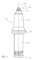
Figure 1 is an external view of a cutting tool according to a specific implementation of the present invention comprising a diamond composite cutting tip supported at a cemented carbide support body that is in turn mounted at a steel holder; -
Figure 2 illustrates a cross section through the tip region of the cutting tool offigure 1 ; -
Figure 3 is an external perspective view of the super-hard diamond based tip offigure 2 ; -
Figure 4 is a magnified cross sectional view of the tip region of the cutting tool offigure 2 ; -
Figure 5 is a cross sectional view of the tip region of a cutting tool according to a further specific implementation; -
Figure 6 is a cross sectional view of the tip region of a cutting tool according to a further specific implementation; -
Figure 7 is a cross sectional view of the tip region of a cutting tool according to a further specific implementation. - Referring to
figure 1 , a cuttingpick tool 100 comprises a silicon carbide-diamond (SCD)composite cutting tip 101 provided at afirst end 106 and bonded to a cementedcarbide support body 102 that is in turn bonded to asteel pick body 103. Thepick body 103 comprises a radially flaredskirt 105 and ashank 104 extending axially rearward from theskirt 105 towards asecond end 107 oftool 100.Tip 101,support body 102 and pickbody 103 are centred around alongitudinal axis 108 extending centrally through thecutting tool 100. - Referring to
figures 2 to 4 , theSCD tip 101 comprises an axiallyforward region 203 and an axially rearward region that represents amount portion 204 oftip 101.Forward region 203 comprises a generally conical shaped configuration having adomed tip end 200 that represents an axially forwardmost part of thetool 100.Mount portion 204 similarly comprises a conical shape configuration and is defined bysurface 202 that tapers axially rearward towardsaxis 108 form awaist region 214 that represents a largest diameter portion oftip 101. Axially forwardmostconical region 203 is defined by a correspondingexternal surface 201 that is aligned substantially coplanar with anexternal surface 207 ofsupport body 102 that extends axially rearward from an axiallyforwardmost rim 206 ofsupport body 102. -
Tip mount portion 204 is received and embedded within a recess (indicated by generally by reference 213) that extends axially rearward from the annularforwardmost rim 206 ofsupport body 102.Recess 213 comprises a complementary conical shape profile and is defined bysidewall 205 that also tapers radially inward fromannular rim 206 towardsaxis 108. A trough or axially rearwardmost region ofrecess 213 is defined by a substantiallyplanar surface 208 at which terminate the taperedrecess sidewall 205.Surface 208 comprises a generally circular shaped profile and is bordered at its perimeter by an annularcurved section 215 that forms a junction with the taperedrecess sidewall 205. Similarly, an axially rearwardmost part oftip 101 is defined by a substantiallyplanar end surface 212. A corresponding curvedannular section 216 is provided at the junction between the planarcircular surface 212 and the conicalexternal surface 202 oftip mount portion 204. - According to the present invention, the shape profile and configuration of the
tip mount portion 204 is complementary and corresponds to the shape profile and configuration ofrecess 213. As such, tip surfaces 202, 212 are configured for positioning in close touching contact withrecess wall 205 andbase surface 208 respectively. This configuration and the correspondingcurved sections support body 102 that surroundsrecess 213. - The cemented
carbide support body 102 further comprises an axiallyrearward region 209 having an axially rearward facingsurface 210.Support body surface 210 is positioned opposed to an axiallyforward facing surface 211 of thesteel pick body 103. - The
SCD tip 101 is bonded to the cementedcarbide support body 102 via abraze layer 217 that extends continuously (near continuously or at least partially) between theopposed tip surface 202,recess wall 205 andplanar surfaces braze layer 217 also extends between the axiallyforwardmost rim 206 ofsupport body 102 and thewaist 214 oftip 101. A relative volume and thickness of thebraze layer 217 is suitable to provide a secure bond and prevent detachment oftip 101 fromsupport body 102. Additionally, the support body rearwardregion 209 is bonded to the axially forward region of thesteel pick body 103 by asimilar braze layer 218 of sufficient volume and thickness to provide a secure bond. The braze layers 217, 218 comprises a metallic material suitable to bond theSCD tip 101 to the cementedcarbide support body 102 and thesupport body 102 to thesteel pick body 103. For example, the braze material may comprise any suitable metal based material and may be different to the material binder that serves as the matrix for the aggregate carbide particles that together represent the metal matrix composite of the cementedcarbide support body 102. Importantly to achieve the required bonding strength between thecomponent tip 101,support body 102 and pickbody 103. The secure attachment of thecomponents - The tip region of the present pick tool is optimised to reduce stress concentrations at the bonding region between the
tip 101 and thesupport body 102 whilst providing a solid mechanical coupling of thetip 101 to thesupport body 102. In particular, an axial length by whichtip 101 is embedded withinsupport body 102 is optimised for mechanical strength such thattip 101 is resistant to dislodgement fromsupport body 102 due to significant impact loading forces attip surface 201 during cutting. A depth ofrecess 213 is also optimised to minimise any weakening of the mechanical strength of thesupport body 102 due to the removal of material by formation ofrecess 213. In particular, an axial depth D ofrecess 213 is defined between the axiallyforwardmost rim 206 andbase surface 208. The total axial length E ofsupport body 102 is defined between the axiallyforwardmost rim 206 and an axially rearwardmost part ofsurface 210. According to the subject invention, recess depth D is approximately 25% of the total axial length E ofsupport body 102. - The relative axial dimensions of
tip 101 are also optimised to maximise the mechanical attachment oftip 101 to supportbody 102. In particular, an axial length A of the generally conical tip forwardregion 203 is defined between the apex of thedomed end 200 and theforwardmost end 300 ofwaist 214. Additionally, an axial length B of thetip mount portion 204 is defined betweencircular end surface 212 and arearward end 301 ofwaist 214. The total axial length C oftip 101 is accordingly defined between the apex ofdome 200 andend surface 212. According to the specific implementation and for optimised mechanical strength when seated withinrecess 213, axial length A is approximately 58% of axial length C whilst axial length B is approximately 38% of axial length C.Tip waist region 214 comprises a generally short cylindrical section representing approximately 5% of the tip total axial length C. Accordingly, approximately 38% of the axial length oftip 101 is accommodated withinrecess 213 that extends approximately 25% axially rearward into the total length of thesupport body 102. - The mechanical attachment strength between
tip 101 andsupport body 102 is further optimised by the relative tapering angles of the tip surfaces 201, 202 at theforward region 203 andmount portion 204. According to the specific implementation, an angle σ by whichtip surface 201 tapers radially outward fromaxis 108 is greater than a corresponding angle α by which thecone surface 202 of thetip mount portion 204 tapers radially inward fromaxis 108. Accordingly, the tip axiallyforward region 203 is slightly 'flatter' than the morepointed mount portion 204. So as to achieve a 'closeness-of-fit' between thetip mount portion 204 andrecess 213, theconical recess sidewall 205 is inclined at the same angle β (relative to axis 108) as angle α. Accordingly, the generally more pointed tip mount region 204 (relative to tip forward region 203) provides a root that is embedded securely within the axially forwardmost region ofsupport body 102. - The mechanical fixation of
tip 101 at thesupport body 102 is provided, in part, by the angled orientation of therecess sidewall 205 relative tobase surface 208 that extends perpendicular toaxis 108. Thetip 101 is therefore effectively 'wedged' in position withinrecess 213 and is prevented from rotation or pivoting within the truncatedconical recess 213. Such an arrangement is advantageous over a part-spherical recess and corresponding part-sphericaltip mount portion 204. -
Figure 5 illustrates a further embodiment of the subject invention in which theSCD tip 101 comprises a spherical shape configuration having anexternal surface 500. Recess 213 atsupport body 102 is defined by a partspherical wall surface 501 that is mated againsttip surface 500 and bonded by thesame braze layer 217 that is described referring tofigures 2 to 4 . According to the further embodiment offigure 5 , the axial length A of theforward region 203 oftip 101 is smaller than the corresponding axial length B of thetip mount portion 204 that is embedded withinrecess 213. Stress concentrations within themount body 102 immediately surroundingrecess 213 are minimised due to the part spherical contact surfaces at the region ofrecess 213. Additionally, and according to the embodiment of thefigure 5 , the relative volume of the SCD material oftip 101 is minimised relative to a volume of the cementedcarbide support body 102. In particular, a volume oftip 101 is approximately 2 to 10% of the volume ofsupport body 102. A secure bond is achieved by configuring a radius of thespherical tip surface 500 to be approximately equal to a radius of partspherical surface 501. -
Figure 6 illustrates a further embodiment of the subject invention in which the axially rearwardmount portion 204 oftip 101 comprises a part spherical shaped configuration whilst the tipforward region 203 comprises the same domed conical shape profile according to the embodiment offigures 2 to 4 . Accordingly,recess 213 is defined by a partspherical surface 601 having a radius approximately equal to a radius of a partspherical tip surface 600. - The arrangement of
figure 6 is optimised to reduce any 'weakening' of thesupport body 102 by creation of therecess 213. Accordingly, a relative depth ofrecess 213 is correspondingly less than recess depth B of the embodiment offigures 2 to 4 . Due to the more 'shallow' recess depth, the axial length A by which tip 101 projects forward from thesupport body rim 206 is greater than the corresponding axial length B by which thetip mount portion 204 is received withinrecess 213. Stress concentrations within thesupport body 102 at the region ofrecess 213 are minimised via the part spherical boundary surfaces 600, 601.Tip 101 is secured to supportbody 102 via a layer of braze material as described with reference tofigures 2 to 4 . -
Figure 7 illustrates a further embodiment of the subject invention in which supportbody 102 does not comprise therecess 213 of the embodiments offigures 2 to 7 and instead comprises a substantially planar axially forwardmostsurface 701 that is aligned perpendicular toaxis 108. Accordingly, an axially rearward region of theSCD tip 101 is formed by a substantiallycoplanar surface 700 that is mated against and opposed to supportbody surface 701. Accordingly,tip 101 comprises a generally conical shape profile and is not embedded intosupport body 102. Acorresponding braze layer 217 is provided betweensurfaces figures 2 to 4 .
Claims (15)
- A cutting pick tool (100) comprising:a cutting tip (101) comprising a diamond composite, the tip (101) having a mount portion (204) extending axially rearward;a cemented carbide support body (102) having an axially forward region (206) and an axially rearward region (209) mounted at a steel pick body (103);the support body (102) having a recess (213) extending axially rearward from the forward region (206), the mount portion (204) received and mated within the recess (213);characterised in that:the recess (213) is defined by a conical sidewall (205) that tapers radially inward in a direction from the forward (206) to the rearward region (209) and towards a central axis (108);the mount portion (204) having a complementary truncated conical shape profile to seat within the recess (213).
- The tool as claimed in claim 1 wherein an axial depth D of the recess (213) in an axial direction of the tool (100) is in a range 20 to 30% of a total axial length of the support body (102).
- The tool as claimed in claims 1 or 2 wherein an angle by which the sidewall (205) tapers radially inward relative to the central axis (108) is in the range 10 to 70°.
- The tool as claimed in claim 3 wherein the range is 20 to 40°.
- The tool as claimed in claim 3 wherein the range is 25 to 35°.
- The tool as claimed in any preceding claim wherein a forward region (203) of the tip (101) comprises a domed apex (200) and is generally conical being defined by a cone surface (201), an angle of the cone surface (201) relative to the axis (108) being at least equal to or greater than an angle by which the sidewall (205) of the recess tapers radially inward relative to the axis (108).
- The tool as claimed in any preceding claim wherein a rearward end of the sidewall (205) terminates at a substantially planar base surface (208).
- The tool as claimed in claim 7 wherein an annular junction between the rearward end of the sidewall (205) and the base surface (208) is curved to provide a gradual transition from the sidewall (205) to the base surface (208) being devoid of an edge or sharp angled portion.
- The tool as claimed in any preceding claim comprising a bonding braze layer positioned between the cutting tip (101) and the support body (102).
- The tool as claimed in any preceding claim comprising a bonding braze layer positioned between the support body (102) and the steel pick body (103).
- The tool as claimed in any preceding claim wherein 55 to 65% of the cutting tip (101) projects axially forward from the support body (102).
- The tool as claimed in claim 6 wherein an external surface that defines the forward region (203) of the tip (101) is aligned substantially coplanar with an external surface that defines the forward region (206) of the support body (102).
- A method of manufacturing a cutting pick tool (100) comprising:forming a diamond composite into a cutting tip (101), the tip having a mount portion (204) extending axially rearward;providing a recess (213) within a cemented carbide support body (102) having an axially forward (206) and rearward region (209), the rearward region (209) mounted at a steel pick body (103), the recess (213) extending rearwardly from the forward region (206) and having a shape and configuration to receive the mount portion (204);characterised by:forming the recess (213) with a conical sidewall (205) that tapers radially inward towards a central axis (108) of the tool (100) in a direction from the forward region (206) to the rearward region (209); andbonding the tip (101) to the support body by brazing.
- The method as claimed in claim 13 further comprising bonding the support body (102) to the steel pick body (103) by brazing.
- A cutting machine comprising a plurality of pick tools (100) as claimed in any one of claims 1 to 12.
Applications Claiming Priority (1)
| Application Number | Priority Date | Filing Date | Title |
|---|---|---|---|
| US201461926423P | 2014-01-13 | 2014-01-13 |
Publications (2)
| Publication Number | Publication Date |
|---|---|
| EP2894293A2 true EP2894293A2 (en) | 2015-07-15 |
| EP2894293A3 EP2894293A3 (en) | 2016-07-20 |
Family
ID=50071511
Family Applications (1)
| Application Number | Title | Priority Date | Filing Date |
|---|---|---|---|
| EP14154696.0A Withdrawn EP2894293A3 (en) | 2014-01-13 | 2014-02-11 | Cutting pick tool |
Country Status (4)
| Country | Link |
|---|---|
| US (1) | US9605538B2 (en) |
| EP (1) | EP2894293A3 (en) |
| CN (1) | CN104775814A (en) |
| AU (1) | AU2014274539A1 (en) |
Cited By (3)
| Publication number | Priority date | Publication date | Assignee | Title |
|---|---|---|---|---|
| WO2019201535A1 (en) * | 2018-04-17 | 2019-10-24 | Betek Gmbh & Co. Kg | Milling pick |
| WO2019201536A1 (en) * | 2018-04-17 | 2019-10-24 | Betek Gmbh & Co. Kg | Milling pick |
| WO2022268660A1 (en) * | 2021-06-23 | 2022-12-29 | Ab Sandvik Coromant | Cutting tool |
Families Citing this family (40)
| Publication number | Priority date | Publication date | Assignee | Title |
|---|---|---|---|---|
| US10598013B2 (en) | 2010-08-27 | 2020-03-24 | The Sollami Company | Bit holder with shortened nose portion |
| US11261731B1 (en) | 2014-04-23 | 2022-03-01 | The Sollami Company | Bit holder and unitary bit/holder for use in shortened depth base blocks |
| US9879531B2 (en) | 2014-02-26 | 2018-01-30 | The Sollami Company | Bit holder shank and differential interference between the shank distal portion and the bit holder block bore |
| US10260342B1 (en) | 2012-10-19 | 2019-04-16 | The Sollami Company | Combination polycrystalline diamond bit and bit holder |
| US10794181B2 (en) | 2014-04-02 | 2020-10-06 | The Sollami Company | Bit/holder with enlarged ballistic tip insert |
| US10968739B1 (en) | 2013-09-18 | 2021-04-06 | The Sollami Company | Diamond tipped unitary holder/bit |
| US10767478B2 (en) | 2013-09-18 | 2020-09-08 | The Sollami Company | Diamond tipped unitary holder/bit |
| US10633971B2 (en) | 2016-03-07 | 2020-04-28 | The Sollami Company | Bit holder with enlarged tire portion and narrowed bit holder block |
| US10947844B1 (en) | 2013-09-18 | 2021-03-16 | The Sollami Company | Diamond Tipped Unitary Holder/Bit |
| US10995613B1 (en) | 2013-09-18 | 2021-05-04 | The Sollami Company | Diamond tipped unitary holder/bit |
| US10876402B2 (en) | 2014-04-02 | 2020-12-29 | The Sollami Company | Bit tip insert |
| US10577931B2 (en) | 2016-03-05 | 2020-03-03 | The Sollami Company | Bit holder (pick) with shortened shank and angular differential between the shank and base block bore |
| US11168563B1 (en) | 2013-10-16 | 2021-11-09 | The Sollami Company | Bit holder with differential interference |
| US11339656B1 (en) | 2014-02-26 | 2022-05-24 | The Sollami Company | Rear of base block |
| US11339654B2 (en) | 2014-04-02 | 2022-05-24 | The Sollami Company | Insert with heat transfer bore |
| US11891895B1 (en) | 2014-04-23 | 2024-02-06 | The Sollami Company | Bit holder with annular rings |
| US9687940B2 (en) * | 2014-11-18 | 2017-06-27 | Baker Hughes Incorporated | Methods and compositions for brazing, and earth-boring tools formed from such methods and compositions |
| US9731384B2 (en) * | 2014-11-18 | 2017-08-15 | Baker Hughes Incorporated | Methods and compositions for brazing |
| US10502056B2 (en) | 2015-09-30 | 2019-12-10 | The Sollami Company | Reverse taper shanks and complementary base block bores for bit assemblies |
| US10612376B1 (en) | 2016-03-15 | 2020-04-07 | The Sollami Company | Bore wear compensating retainer and washer |
| US10612375B2 (en) | 2016-04-01 | 2020-04-07 | The Sollami Company | Bit retainer |
| US10294786B2 (en) * | 2016-05-24 | 2019-05-21 | Kennametal Inc. | Rotatable cutting tool with cutting insert and bolster |
| USD839936S1 (en) | 2016-05-24 | 2019-02-05 | Kennametal Inc. | Cutting insert and bolster |
| GB201611743D0 (en) * | 2016-07-05 | 2016-08-17 | Barry John J | Bonded assembly of dissimilar materials |
| US10876401B1 (en) | 2016-07-26 | 2020-12-29 | The Sollami Company | Rotational style tool bit assembly |
| CN106968669A (en) * | 2016-08-08 | 2017-07-21 | 温州宝通机械制造有限公司 | A kind of pick |
| US10465512B2 (en) | 2017-02-28 | 2019-11-05 | Kennametal Inc. | Rotatable cutting tool |
| US11187080B2 (en) * | 2018-04-24 | 2021-11-30 | The Sollami Company | Conical bit with diamond insert |
| US10968738B1 (en) | 2017-03-24 | 2021-04-06 | The Sollami Company | Remanufactured conical bit |
| GB201711850D0 (en) * | 2017-07-24 | 2017-09-06 | Element Six (Uk) Ltd | Super-hard bits, super-hard tips for same, tools comprising same and methods for making same |
| US11279012B1 (en) | 2017-09-15 | 2022-03-22 | The Sollami Company | Retainer insertion and extraction tool |
| US20200018018A1 (en) * | 2018-07-16 | 2020-01-16 | Trackmate LLC | Tamping tool |
| US11103939B2 (en) | 2018-07-18 | 2021-08-31 | The Sollami Company | Rotatable bit cartridge |
| GB201901712D0 (en) | 2019-02-07 | 2019-03-27 | Element Six Gmbh | Pick tool for road milling |
| US12345158B1 (en) | 2019-06-20 | 2025-07-01 | The Sollami Company | Bit tip insert |
| CN110560866A (en) * | 2019-10-23 | 2019-12-13 | 西安泾渭钻探机具制造有限公司 | A kind of diamond pick and its production method |
| US11092008B2 (en) | 2019-12-03 | 2021-08-17 | Ironhawk Industrial Distribution LLC | Grader bit |
| US12560085B2 (en) * | 2023-08-09 | 2026-02-24 | Kennametal Inc. | Rotatable cutting tool with cutting insert and bolster |
| WO2025259261A1 (en) | 2024-06-10 | 2025-12-18 | Ojanen Randall W | Rotatable cutting bit with keyed alignment |
| US12480366B1 (en) | 2024-07-18 | 2025-11-25 | Kennametal Inc. | Earth cutting tool, earth cutting device, and related methods |
Family Cites Families (20)
| Publication number | Priority date | Publication date | Assignee | Title |
|---|---|---|---|---|
| GB954130A (en) * | 1962-04-27 | 1964-04-02 | Minsup Mining Supplies | Improvements in or relating to coal-cutter picks |
| GB1114156A (en) * | 1964-09-01 | 1968-05-15 | Coal Industry Patents Ltd | Improvements in or relating to cutter picks |
| US3342532A (en) * | 1965-03-15 | 1967-09-19 | Cincinnati Mine Machinery Co | Cutting tool comprising holder freely rotatable in socket with bit frictionally attached |
| US4502734A (en) * | 1981-06-25 | 1985-03-05 | Allan David T | Scabbler bits |
| ZA846759B (en) * | 1983-09-05 | 1985-02-27 | ||
| US4702525A (en) * | 1985-04-08 | 1987-10-27 | Sollami Phillip A | Conical bit |
| SE463573B (en) * | 1989-04-24 | 1990-12-10 | Sandvik Ab | TOOLS AND TOOL BODY FOR CHANGING SOLID MATERIALS |
| US5348108A (en) | 1991-03-01 | 1994-09-20 | Baker Hughes Incorporated | Rolling cone bit with improved wear resistant inserts |
| US5261499A (en) * | 1992-07-15 | 1993-11-16 | Kennametal Inc. | Two-piece rotatable cutting bit |
| RU2083821C1 (en) * | 1995-08-10 | 1997-07-10 | Товарищество с ограниченной ответственностью "ПИГМА" | Tool for crushing mineral and artificial materials |
| US5823632A (en) * | 1996-06-13 | 1998-10-20 | Burkett; Kenneth H. | Self-sharpening nosepiece with skirt for attack tools |
| CA2408970C (en) | 2000-05-18 | 2009-05-12 | Commonwealth Scientific And Industrial Research Organisation | Cutting tool and method of using same |
| AU2005202371B2 (en) | 2005-05-31 | 2010-09-23 | Sandvik Intellectual Property Ab | Method for manufacturing a cutting pick |
| US7611210B2 (en) * | 2006-08-21 | 2009-11-03 | Kennametal Inc. | Cutting bit body and method for making the same |
| US20090256413A1 (en) * | 2008-04-11 | 2009-10-15 | Majagi Shivanand I | Cutting bit useful for impingement of earth strata |
| AU2012201292A1 (en) * | 2011-03-21 | 2012-10-11 | Kennametal Inc. | Cutting tool |
| GB201113013D0 (en) | 2011-07-28 | 2011-09-14 | Element Six Abrasive Sa | Tip for a pick tool |
| CN202194661U (en) * | 2011-08-26 | 2012-04-18 | 河南四方达超硬材料股份有限公司 | Polycrystalline diamond enhanced cutting tooth |
| US20140054951A1 (en) * | 2012-08-22 | 2014-02-27 | Kennametal Inc. | Cutting Tool With Insert Having A Tapered Bottom |
| US9074471B2 (en) * | 2013-08-05 | 2015-07-07 | Kennametal Inc. | Insert with offset apex for a cutter bit and a cutter bit having the same |
-
2014
- 2014-02-11 EP EP14154696.0A patent/EP2894293A3/en not_active Withdrawn
- 2014-12-09 AU AU2014274539A patent/AU2014274539A1/en not_active Abandoned
-
2015
- 2015-01-12 US US14/594,358 patent/US9605538B2/en not_active Expired - Fee Related
- 2015-01-13 CN CN201510016196.8A patent/CN104775814A/en active Pending
Cited By (5)
| Publication number | Priority date | Publication date | Assignee | Title |
|---|---|---|---|---|
| WO2019201535A1 (en) * | 2018-04-17 | 2019-10-24 | Betek Gmbh & Co. Kg | Milling pick |
| WO2019201536A1 (en) * | 2018-04-17 | 2019-10-24 | Betek Gmbh & Co. Kg | Milling pick |
| US11339655B2 (en) | 2018-04-17 | 2022-05-24 | Betek Gmbh & Co. Kg | Milling pick |
| WO2022268660A1 (en) * | 2021-06-23 | 2022-12-29 | Ab Sandvik Coromant | Cutting tool |
| JP2024527282A (en) * | 2021-06-23 | 2024-07-24 | エービー サンドビック コロマント | Cutting tools |
Also Published As
| Publication number | Publication date |
|---|---|
| AU2014274539A1 (en) | 2015-07-30 |
| US9605538B2 (en) | 2017-03-28 |
| CN104775814A (en) | 2015-07-15 |
| EP2894293A3 (en) | 2016-07-20 |
| US20150198040A1 (en) | 2015-07-16 |
Similar Documents
| Publication | Publication Date | Title |
|---|---|---|
| US9605538B2 (en) | Cutting pick tool | |
| US6868848B2 (en) | Cutting tool and method of using same | |
| EP2799659A1 (en) | Percussive rock drill bit | |
| CN101438028A (en) | Cutting tool and method of assembling a cutting tool | |
| CN102421990A (en) | Cutting Tools for Mining Machines | |
| US20140175853A1 (en) | Pick For Earthworking Machine | |
| WO2011025510A1 (en) | Pcd percussion drill bit | |
| CN112105797A (en) | Cutting assembly | |
| CN112074649A (en) | Cutting components | |
| EP3864256B1 (en) | Pick tool for road milling and mining | |
| CN115605664A (en) | disc cutter | |
| US9347276B2 (en) | Two prong rotary drill bit with cutting insert having edge preparation | |
| JP2023024501A (en) | pick tool for road milling | |
| US8777326B2 (en) | Pick with hardened core assembly | |
| GB2521756A (en) | Strike constructions, picks comprising same and methods for making same | |
| US20200277854A1 (en) | Strike tip for a pick tool | |
| US11952896B2 (en) | Rotary tool with thermally stable diamond | |
| CN110560866A (en) | A kind of diamond pick and its production method |
Legal Events
| Date | Code | Title | Description |
|---|---|---|---|
| PUAI | Public reference made under article 153(3) epc to a published international application that has entered the european phase |
Free format text: ORIGINAL CODE: 0009012 |
|
| 17P | Request for examination filed |
Effective date: 20140211 |
|
| AK | Designated contracting states |
Kind code of ref document: A2 Designated state(s): AL AT BE BG CH CY CZ DE DK EE ES FI FR GB GR HR HU IE IS IT LI LT LU LV MC MK MT NL NO PL PT RO RS SE SI SK SM TR |
|
| AX | Request for extension of the european patent |
Extension state: BA ME |
|
| PUAL | Search report despatched |
Free format text: ORIGINAL CODE: 0009013 |
|
| AK | Designated contracting states |
Kind code of ref document: A3 Designated state(s): AL AT BE BG CH CY CZ DE DK EE ES FI FR GB GR HR HU IE IS IT LI LT LU LV MC MK MT NL NO PL PT RO RS SE SI SK SM TR |
|
| AX | Request for extension of the european patent |
Extension state: BA ME |
|
| RIC1 | Information provided on ipc code assigned before grant |
Ipc: E21C 35/183 20060101AFI20160610BHEP |
|
| 17Q | First examination report despatched |
Effective date: 20160714 |
|
| RBV | Designated contracting states (corrected) |
Designated state(s): AL AT BE BG CH CY CZ DE DK EE ES FI FR GB GR HR HU IE IS IT LI LT LU LV MC MK MT NL NO PL PT RO RS SE SI SK SM TR |
|
| STAA | Information on the status of an ep patent application or granted ep patent |
Free format text: STATUS: THE APPLICATION HAS BEEN WITHDRAWN |
|
| 18W | Application withdrawn |
Effective date: 20170317 |