EP2894188A1 - Process for producing acrylonitrile-based polymer solution, shearing device, process for producing acrylonitrile-based fiber, and process for producing carbon fiber - Google Patents
Process for producing acrylonitrile-based polymer solution, shearing device, process for producing acrylonitrile-based fiber, and process for producing carbon fiber Download PDFInfo
- Publication number
- EP2894188A1 EP2894188A1 EP13835951.8A EP13835951A EP2894188A1 EP 2894188 A1 EP2894188 A1 EP 2894188A1 EP 13835951 A EP13835951 A EP 13835951A EP 2894188 A1 EP2894188 A1 EP 2894188A1
- Authority
- EP
- European Patent Office
- Prior art keywords
- acrylonitrile
- based polymer
- rotor
- polymer solution
- mixture
- Prior art date
- Legal status (The legal status is an assumption and is not a legal conclusion. Google has not performed a legal analysis and makes no representation as to the accuracy of the status listed.)
- Withdrawn
Links
Images
Classifications
-
- C—CHEMISTRY; METALLURGY
- C08—ORGANIC MACROMOLECULAR COMPOUNDS; THEIR PREPARATION OR CHEMICAL WORKING-UP; COMPOSITIONS BASED THEREON
- C08J—WORKING-UP; GENERAL PROCESSES OF COMPOUNDING; AFTER-TREATMENT NOT COVERED BY SUBCLASSES C08B, C08C, C08F, C08G or C08H
- C08J3/00—Processes of treating or compounding macromolecular substances
- C08J3/02—Making solutions, dispersions, lattices or gels by other methods than by solution, emulsion or suspension polymerisation techniques
- C08J3/09—Making solutions, dispersions, lattices or gels by other methods than by solution, emulsion or suspension polymerisation techniques in organic liquids
- C08J3/11—Making solutions, dispersions, lattices or gels by other methods than by solution, emulsion or suspension polymerisation techniques in organic liquids from solid polymers
-
- B—PERFORMING OPERATIONS; TRANSPORTING
- B01—PHYSICAL OR CHEMICAL PROCESSES OR APPARATUS IN GENERAL
- B01F—MIXING, e.g. DISSOLVING, EMULSIFYING OR DISPERSING
- B01F25/00—Flow mixers; Mixers for falling materials, e.g. solid particles
- B01F25/40—Static mixers
- B01F25/44—Mixers in which the components are pressed through slits
-
- B—PERFORMING OPERATIONS; TRANSPORTING
- B01—PHYSICAL OR CHEMICAL PROCESSES OR APPARATUS IN GENERAL
- B01F—MIXING, e.g. DISSOLVING, EMULSIFYING OR DISPERSING
- B01F27/00—Mixers with rotary stirring devices in fixed receptacles; Kneaders
- B01F27/27—Mixers with stator-rotor systems, e.g. with intermeshing teeth or cylinders or having orifices
- B01F27/272—Mixers with stator-rotor systems, e.g. with intermeshing teeth or cylinders or having orifices with means for moving the materials to be mixed axially between the surfaces of the rotor and the stator, e.g. the stator rotor system formed by conical or cylindrical surfaces
- B01F27/2721—Mixers with stator-rotor systems, e.g. with intermeshing teeth or cylinders or having orifices with means for moving the materials to be mixed axially between the surfaces of the rotor and the stator, e.g. the stator rotor system formed by conical or cylindrical surfaces provided with intermeshing elements
-
- B—PERFORMING OPERATIONS; TRANSPORTING
- B01—PHYSICAL OR CHEMICAL PROCESSES OR APPARATUS IN GENERAL
- B01F—MIXING, e.g. DISSOLVING, EMULSIFYING OR DISPERSING
- B01F35/00—Accessories for mixers; Auxiliary operations or auxiliary devices; Parts or details of general application
- B01F35/90—Heating or cooling systems
- B01F35/92—Heating or cooling systems for heating the outside of the receptacle, e.g. heated jackets or burners
-
- B—PERFORMING OPERATIONS; TRANSPORTING
- B29—WORKING OF PLASTICS; WORKING OF SUBSTANCES IN A PLASTIC STATE IN GENERAL
- B29C—SHAPING OR JOINING OF PLASTICS; SHAPING OF MATERIAL IN A PLASTIC STATE, NOT OTHERWISE PROVIDED FOR; AFTER-TREATMENT OF THE SHAPED PRODUCTS, e.g. REPAIRING
- B29C48/00—Extrusion moulding, i.e. expressing the moulding material through a die or nozzle which imparts the desired form; Apparatus therefor
- B29C48/03—Extrusion moulding, i.e. expressing the moulding material through a die or nozzle which imparts the desired form; Apparatus therefor characterised by the shape of the extruded material at extrusion
-
- B—PERFORMING OPERATIONS; TRANSPORTING
- B29—WORKING OF PLASTICS; WORKING OF SUBSTANCES IN A PLASTIC STATE IN GENERAL
- B29C—SHAPING OR JOINING OF PLASTICS; SHAPING OF MATERIAL IN A PLASTIC STATE, NOT OTHERWISE PROVIDED FOR; AFTER-TREATMENT OF THE SHAPED PRODUCTS, e.g. REPAIRING
- B29C48/00—Extrusion moulding, i.e. expressing the moulding material through a die or nozzle which imparts the desired form; Apparatus therefor
- B29C48/03—Extrusion moulding, i.e. expressing the moulding material through a die or nozzle which imparts the desired form; Apparatus therefor characterised by the shape of the extruded material at extrusion
- B29C48/05—Filamentary, e.g. strands
-
- C—CHEMISTRY; METALLURGY
- C08—ORGANIC MACROMOLECULAR COMPOUNDS; THEIR PREPARATION OR CHEMICAL WORKING-UP; COMPOSITIONS BASED THEREON
- C08J—WORKING-UP; GENERAL PROCESSES OF COMPOUNDING; AFTER-TREATMENT NOT COVERED BY SUBCLASSES C08B, C08C, C08F, C08G or C08H
- C08J3/00—Processes of treating or compounding macromolecular substances
- C08J3/02—Making solutions, dispersions, lattices or gels by other methods than by solution, emulsion or suspension polymerisation techniques
- C08J3/09—Making solutions, dispersions, lattices or gels by other methods than by solution, emulsion or suspension polymerisation techniques in organic liquids
- C08J3/091—Making solutions, dispersions, lattices or gels by other methods than by solution, emulsion or suspension polymerisation techniques in organic liquids characterised by the chemical constitution of the organic liquid
- C08J3/096—Nitrogen containing compounds
-
- D—TEXTILES; PAPER
- D01—NATURAL OR MAN-MADE THREADS OR FIBRES; SPINNING
- D01D—MECHANICAL METHODS OR APPARATUS IN THE MANUFACTURE OF ARTIFICIAL FILAMENTS, THREADS, FIBRES, BRISTLES OR RIBBONS
- D01D1/00—Treatment of filament-forming or like material
- D01D1/02—Preparation of spinning solutions
-
- D—TEXTILES; PAPER
- D01—NATURAL OR MAN-MADE THREADS OR FIBRES; SPINNING
- D01F—CHEMICAL FEATURES IN THE MANUFACTURE OF ARTIFICIAL FILAMENTS, THREADS, FIBRES, BRISTLES OR RIBBONS; APPARATUS SPECIALLY ADAPTED FOR THE MANUFACTURE OF CARBON FILAMENTS
- D01F6/00—Monocomponent artificial filaments or the like of synthetic polymers; Manufacture thereof
- D01F6/02—Monocomponent artificial filaments or the like of synthetic polymers; Manufacture thereof from homopolymers obtained by reactions only involving carbon-to-carbon unsaturated bonds
- D01F6/18—Monocomponent artificial filaments or the like of synthetic polymers; Manufacture thereof from homopolymers obtained by reactions only involving carbon-to-carbon unsaturated bonds from polymers of unsaturated nitriles, e.g. polyacrylonitrile, polyvinylidene cyanide
-
- D—TEXTILES; PAPER
- D01—NATURAL OR MAN-MADE THREADS OR FIBRES; SPINNING
- D01F—CHEMICAL FEATURES IN THE MANUFACTURE OF ARTIFICIAL FILAMENTS, THREADS, FIBRES, BRISTLES OR RIBBONS; APPARATUS SPECIALLY ADAPTED FOR THE MANUFACTURE OF CARBON FILAMENTS
- D01F6/00—Monocomponent artificial filaments or the like of synthetic polymers; Manufacture thereof
- D01F6/28—Monocomponent artificial filaments or the like of synthetic polymers; Manufacture thereof from copolymers obtained by reactions only involving carbon-to-carbon unsaturated bonds
- D01F6/38—Monocomponent artificial filaments or the like of synthetic polymers; Manufacture thereof from copolymers obtained by reactions only involving carbon-to-carbon unsaturated bonds comprising unsaturated nitriles as the major constituent
-
- D—TEXTILES; PAPER
- D01—NATURAL OR MAN-MADE THREADS OR FIBRES; SPINNING
- D01F—CHEMICAL FEATURES IN THE MANUFACTURE OF ARTIFICIAL FILAMENTS, THREADS, FIBRES, BRISTLES OR RIBBONS; APPARATUS SPECIALLY ADAPTED FOR THE MANUFACTURE OF CARBON FILAMENTS
- D01F9/00—Artificial filaments or the like of other substances; Manufacture thereof; Apparatus specially adapted for the manufacture of carbon filaments
- D01F9/08—Artificial filaments or the like of other substances; Manufacture thereof; Apparatus specially adapted for the manufacture of carbon filaments of inorganic material
- D01F9/12—Carbon filaments; Apparatus specially adapted for the manufacture thereof
- D01F9/14—Carbon filaments; Apparatus specially adapted for the manufacture thereof by decomposition of organic filaments
- D01F9/20—Carbon filaments; Apparatus specially adapted for the manufacture thereof by decomposition of organic filaments from polyaddition, polycondensation or polymerisation products
- D01F9/21—Carbon filaments; Apparatus specially adapted for the manufacture thereof by decomposition of organic filaments from polyaddition, polycondensation or polymerisation products from macromolecular compounds obtained by reactions only involving carbon-to-carbon unsaturated bonds
- D01F9/22—Carbon filaments; Apparatus specially adapted for the manufacture thereof by decomposition of organic filaments from polyaddition, polycondensation or polymerisation products from macromolecular compounds obtained by reactions only involving carbon-to-carbon unsaturated bonds from polyacrylonitriles
-
- C—CHEMISTRY; METALLURGY
- C08—ORGANIC MACROMOLECULAR COMPOUNDS; THEIR PREPARATION OR CHEMICAL WORKING-UP; COMPOSITIONS BASED THEREON
- C08J—WORKING-UP; GENERAL PROCESSES OF COMPOUNDING; AFTER-TREATMENT NOT COVERED BY SUBCLASSES C08B, C08C, C08F, C08G or C08H
- C08J2333/00—Characterised by the use of homopolymers or copolymers of compounds having one or more unsaturated aliphatic radicals, each having only one carbon-to-carbon double bond, and only one being terminated by only one carboxyl radical, or of salts, anhydrides, esters, amides, imides, or nitriles thereof; Derivatives of such polymers
- C08J2333/18—Homopolymers or copolymers of nitriles
- C08J2333/20—Homopolymers or copolymers of acrylonitrile
Definitions
- the present invention relates to a process for producing an acrylonitrile-based polymer solution, and it relates to a process for producing an acrylonitrile-based polymer solution having no gel production as the acrylonitrile-based polymer is homogeneously dissolved in a solvent.
- the invention also relates to a shearing device suitable for performing the aforementioned process, a process for producing an acrylonitrile-based fiber using the aforementioned process, and a process for producing a carbon fiber having the acrylonitrile-based fiber as a precursor.
- a poor dispersion product When the acrylonitrile-based polymer is mixed and dispersed as a powder in a solvent, only the perimeter of a lump of acrylonitrile-based polymer powder is dissolved by the solvent and the solvent does not permeate into the inside of the lump, and thus a poor dispersion product may be easily yielded. Such a poor dispersion product remains undissolved until the end even after it passes through a heat exchanger of a dissolving step, and thus there is a case in which an undissolved acrylonitrile-based polymer is present as residuals. Due to such undissolved product, a filter for filtering the acrylonitrile-based polymer may be easily clogged.
- Patent Document 1 there is described a dissolving process for dissolving an acrylonitrile-based polymer by using a device equipped with a cylinder and a rotor installed in the inside of the cylinder, in which pin members are installed projectingly on each of them, and the dissolving is achieved based on heat generation caused by the shear force occurring between the pin members.
- Patent Document 1 JP 2002-45671 A
- Patent Document 1 The dissolving process of Patent Document 1 is, from the viewpoint of homogeneously dissolving an acrylonitrile-based polymer in a solvent, an improved process. However, it is still required to further improve the solubility of the acrylonitrile-based polymer. In fact, when estimation is made based on the description of Examples of Patent Document 1, the index W, which will be later described in detail, is believed to be about 0.2 kWh/kg. Thus, the level of pressure increase (an indicator of solubility) is improved according to a filtering pressure increase test compared to the case of using a double-tube type heat exchanger. However, a further improvement of solubility is required.
- An object of the invention is to provide a process for producing stably an acrylonitrile-based polymer solution with which an acrylonitrile-based polymer solution can be homogeneously and efficiently dissolved in a solvent so that the clogging of a filter or a spinning nozzle is inhibited, and also a shearing device which can be suitably used for performing the process.
- Another object is to provide a process for producing an acrylonitrile-based fiber using the acrylonitrile-based polymer solution obtained therefrom and a process for producing a carbon fiber having the acrylonitrile-based fiber as a precursor.
- a process for producing an acrylonitrile-based polymer solution, a shearing device, a process for producing an acrylonitrile-based fiber, and a process for producing a carbon fiber as described below are provided.
- a process for producing an acrylonitrile-based polymer solution with which it is possible to homogeneously and efficiently dissolve an acrylonitrile-based polymer in a solvent, inhibit clogging of a filter or spinning nozzle, and stably produce an acrylonitrile-based polymer solution, and a shearing device which can be suitably used for performing the process are provided.
- a process for producing an acrylonitrile-based fiber using the acrylonitrile-based polymer solution obtained therefrom and a process for producing a carbon fiber having an acrylonitrile-based fiber as a precursor are also provided.
- a mixture of an acrylonitrile-based polymer and a solvent is supplied to a shearing device (in particular, a dispersion chamber of the device).
- the shearing device has a cylinder and a rotor that rotates inside the cylinder.
- the dispersion chamber is provided between an inner wall of the cylinder and an outer wall of the rotor. By rotating the rotor, shear force is applied to the mixture inside the dispersion chamber. By doing so, at least the polymer is dispersed and it is also possibly accompanied with dissolution of the polymer.
- shear force is applied to a mixture in a dispersion chamber and the obtained mixture is then heated to yield an acrylonitrile-based polymer solution.
- shear force is applied to a mixture in a dispersion chamber to yield an acrylonitrile-based polymer solution.
- heating is not performed after applying shear force.
- W 1 is an electric power (kW) required for rotating the rotor at the time of applying shear force to the mixture.
- W 2 is an electric power (kW) required for obtaining the same rotation number as the rotation number of the rotor at the time of obtaining W 1 when, instead of the mixture, water is used in the same mass flow amount as the mixture.
- M is a mass flow amount (kg/h) of the acrylonitrile-based polymer supplied to the dispersion chamber at the time of obtaining W 1 .
- the above W represents an electric power obtained from the electric power (W 1 - W 2 ), which is obtained by subtracting W 2 as an electric power at the time of using water (water in the same mass flow amount as the mixture for obtaining W 1 ) with the same rotation number as the rotation number of having W 1 from W 1 as an electric power for rotating the rotor in the mixture, expressed in terms of a unit mass flow amount of the acrylonitrile-based polymer in the mixture present in a dispersion chamber of a shearing device. Namely, it can be said that W is a value of shear force applied to the mixture while it stays within a shearing device, but expressed in electric power.
- a system being applied with W 2 is basically the same as a system being applied with W 1 except that the same mass flow amount of water is used instead of the mixture (consequently, measured W 1 and W 2 are different from each other).
- W 1 , W 2 , and M are as defined in the above formula I.
- a mixture of an acrylonitrile-based polymer and a solvent is supplied to the supply tank 1, a mixture of an acrylonitrile-based polymer and a solvent is supplied.
- a supply pump 2 the mixture is supplied to a shearing device 3, in which the acrylonitrile-based polymer is dispersed (in general, at least part of the polymer is dissolved in addition to dispersion of the polymer).
- the liquid (mixture) discharged from the shearing device is sent to a heating type dissolving device 4, in which the polymer is dissolved by heating.
- the mixture is cooled in a cooling device 5 and pressurized by a spinning supply pump 6, and then filtered by a filtering filter 7.
- the acrylonitrile-based polymer solution obtained from the device can be supplied to, as a dope for spinning, a spinneret 8 of a spinning device for obtaining an acrylonitrile-based fiber.
- the device is not a batch type but a flow type shearing device.
- This device is suitable for performing the first mode of the process for producing an acrylonitrile-based polymer solution described above.
- heating should be performed by the heating type dissolving device 4 of the device.
- the second mode can be performed.
- the upper limit of W at the time of applying shear force to a mixture of an acrylonitrile-based polymer solution and a solvent is preferably 4.00 kWh/kg or less.
- the W is more preferably 2.70 kWh/kg or less. It is more preferably less than 1.60 kWh/kg.
- an acrylonitrile-based polymer solution can be obtained even without heating after a step of applying shear force (shear force applying step).
- shear force applying step when it is 4.00 kWh/kg or less, heating may be performed after the shear force applying step.
- Whether to perform heating after the shear force applying step can be suitably selected based on a composition of the mixture, or the like.
- the W is preferably 2.00 kWh/kg or more. Furthermore, from the viewpoint of preventing gellation caused by high temperature, the W is preferably 5.00 kWh/kg or less. It is more preferably 3.60 kWh/kg or less, and even more preferably 3.00 kWh/kg or less.
- the mixture is cooled by adding a jacket for cooling the mixture to at least part of the shearing device (in particular, perimeter of a device).
- the temperature of the mixture at an exit of the dispersion chamber is preferably 40 to 115°C.
- the polymer is slowly dissolved in a solvent so that it becomes easy to have homogeneous dissolving. Furthermore, when it is 115°C or lower, gelation of the dissolved mixture can be easily prevented.
- the exit temperature is more preferably 100°C or lower, and even more preferably 80°C or lower.
- This device is a pin type mixer having a cylinder 10 with a barrel shape.
- a rotor 9 with a column shape is installed such that it can rotate at high speed while its axial center line is in line with the axial center line of the cylinder 10.
- Each of the rotor 9 and the cylinder 10 has pin members 12 and 13, and the pin members 12 and 13 are in a positional relationship in which they are not in contact with each other.
- a dispersion chamber 14 is formed between the inner wall of the cylinder 10 and the outer wall of the rotor 9.
- the outer shape of the rotor (excluding the pin member) has a rotating-body shape, and at least the inner wall of the cylinder (excluding the pin member) also has a rotating-body shape.
- an inlet for supplying a mixture of the polymer and a solvent sent by the pump to the inside of the cylinder 10 is formed and also an outlet for the obtained polymer solution is formed on the top part of the same cylinder 10.
- the flow paths 11a and 11b for heating or cooling fluid are formed at each of the cylinder 10 and the rotor 9. By flowing heating or cooling fluid along those flow paths, it becomes easier to control the temperature of the mixture (liquid). However, it is not entirely necessary to use those flow paths.
- W 1 is an electric power measured at the time of rotating the rotor 9 with a certain rotation number when a mixture of an acrylonitrile-based polymer and a solvent is supplied to a dispersion chamber.
- W 2 is an electric power measured in the same manner as W 1 except that, instead of the mixture, water is used in the same mass flow amount as the mixture.
- M is a mass flow amount of the acrylonitrile-based polymer which is present in the mixture at the time of measuring W 1 .
- shear force is applied to the mixture by rotating the barrel-shaped rotor 9 having the pin member 12 while the mixture passes through the device and thus homogeneous mixing of an acrylonitrile-based polymer and a solvent is achieved.
- the target W can be obtained by modifying the rotation number of the rotor 9.
- a known device can be used as a shearing device.
- the shape of the shearing device is not limited as long as it can apply shear force to a fluid with high viscosity.
- examples thereof include a kneader, an auger, a helical rotor, a screw extruder, a thermal processor, a pin mixer, a roll mixer, a tapered roll mixer, an internal mixer, a continuous mixer, a banburry mixer, a gear compounder, a meat mill, an attritor, and a sand grinder.
- the pin mixer is preferable.
- the time for the mixture to stay in a dispersion chamber of the shearing device is preferably 3 to 800 seconds.
- dwell time is 3 seconds or longer, it becomes easy to disperse the polymer homogeneously in a solvent by applying shear force to the mixture.
- the dwell time is preferably 10 seconds or longer, and more preferably 15 seconds or longer.
- the shear force applied to the mixture is not excessive so that an occurrence of gelation caused by heat generation can be easily suppressed.
- the dwell time is preferably 300 seconds or shorter, and more preferably 200 seconds or shorter.
- the dwell time is preferably 600 to 1500 seconds.
- the dwell time is preferably 1000 seconds or shorter, and more preferably 800 seconds or shorter.
- a distance between the tip of the pin and the wall facing the tip of the pin is preferably 2 mm or more but less than 5 mm.
- a distance between the tip of the pin member 12, which is projectingly installed on an outer wall of the rotor, and an inner wall of the cylinder 10 is preferably 2 mm or more but less than 5 mm.
- a distance between the tip of the pin member 13, which is projectingly installed on an inner wall of the cylinder, and an outer wall of the rotor 9 is 2 mm or more but less than 5 mm.
- the pin member When the distance is 2 mm or more, the pin member does not touch a wall surface even when there is mechanical vibration or eccentricity, and thus stable operation can be easily achieved. Furthermore, when the distance is less than 5 mm, it is easy to proceed with dissolving by generating shear force.
- the axial direction distance between neighboring pin members is preferably 2 mm to 10 mm when the pin member 13 projectingly installed on an inner peripheral surface of the cylinder and the pin member 12 projectingly installed on an outer peripheral surface of the rotor come nearest to each other.
- the distance is 2 mm or more, the pin members are not in contact with each other even when there is mechanical vibration or eccentricity, and thus stable operation can be easily achieved.
- the distance is 10 mm or less, it is easy to proceed with dissolving by generating shear force.
- heating after the step of applying shear force can be performed by using a suitable heating device which enables heating to the temperature at which the acrylonitrile-based polymer is dissolved in a solvent.
- a suitable heating device which enables heating to the temperature at which the acrylonitrile-based polymer is dissolved in a solvent.
- the heating device which may be used include a heat exchanger (a multi-tube type heat exchanger, a plate type heat exchanger, or the like) and a temperature control tank.
- the heating can be performed by using a heating type dissolving device illustrated in Fig. 3 .
- the device can be installed behind the shearing device.
- a heating medium is supplied from the heating medium inlet 20 provided on the body 23 and the heating medium is discharged from the heating medium exit 19.
- a liquid for heating (a mixture of an acrylonitrile-based polymer and a solvent) flows starting from the liquid inlet 17, passes through the tube 21 via the inlet side channel cover 15, and is discharged from the liquid exit 18 via the exit side channel cover 16.
- the mixing element (static mixer) 22 is disposed inside the tube. Heat is applied from the heating medium to the liquid for heating the inside of the tube. Furthermore, as the liquid for heating is stirred by the mixer element, the polymer is dissolved.
- the mixture is preferably heated to 60°C to 150°C.
- the acrylonitrile-based polymer is easily dissolved in a solvent.
- the temperature is preferably 80°C to 140°C. More preferably, it is 90°C to 130°C. Particularly preferably, it is 100°C to 130°C.
- the heating time for the heating which is performed after the step of applying shear force is preferably 1 minute to 15 minutes. When it is 1 minute or longer, it becomes easy for a mixture of an acrylonitrile-based polymer to dissolve sufficiently. Furthermore, when it is 15 minutes or shorter, gelation can be easily prevented. It is more preferably 3 to 10 minutes.
- the acrylonitrile-based polymer is a polymer which contains acrylonitrile unit as a main constitutional unit.
- the ratio of the acrylonitrile unit in the acrylonitrile-based polymer is 80% by mass or more, for example. It is 92% by mass or more, and particularly 96% by mass or more.
- a monomer other than acrylonitrile constituting the acrylonitrile-based polymer can be suitably selected from a vinyl-based monomer which can copolymerize with acrylonitrile. Preferred examples thereof include a vinyl-based monomer which enhances hydrophilicity of the acrylonitrile-based polymer and a vinyl-based monomer which has an effect of promoting flame resistance.
- Examples of the monomer which enhances hydrophilicity of the acrylonitrile-based polymer include a vinyl compound having a hydrophilic functional group such as a carboxy group, a sulfo group, an amino group, an amide group, or a hydroxyl group.
- Examples of the monomer having a carboxy group include acrylic acid, methacrylic acid, itaconic acid, crotonic acid, citraconic acid, ethacrylic acid, maleic acid, and mesaconic acid. Among them, acrylic acid, methacrylic acid, and itaconic acid are preferable.
- Examples of the monomer having a sulfo group include allyl sulfonic acid, methallyl sulfonic acid, styrene sulfonic acid, 2-acrylamide-2-methylpropane sulfonic acid, vinyl sulfonic acid, and sulfoporpyl methacrylate. Among them, allyl sulflonic acid, methallyl sulfonic acid, styrene sulfonic acid, and 2-acrylamide-2-methylpropane sulfonic acid are preferable.
- Examples of the monomer having an amino group include dimethylaminoethyl methacrylate, diethylaminoethyl methacrylate, dimethylaminoethyl acrylate, diethylaminoethyl acrylate, tertiary butylaminoethyl methacrylate, allylamine, o-aminostyrene, and p-aminostyrene.
- dimethylaminoethyl methacrylate, diethylaminoethyl methacrylate, dimethylaminoethyl acrylate, and diethylaminoethyl acrylate are preferable.
- Preferred examples of the monomer having an amide group include acrylamide, methacrylamide, dimethyl acrylamide, and crotone amide.
- Examples of the monomer having a hydroxyl group include hydroxymethyl methacrylate, hydroxymethyl acrylate, 2-hydroxyethyl methacrylate, 2-hydroxyethyl acrylate, 3-hydroxypropyl methacrylate, 3-hydroxypropyl acrylate, 2-hydroxypropyl methacrylate, and 2-hydroxypropyl acrylate.
- the acrylonitrile-based polymer can have improved hydrophilicity.
- a precursor fiber obtained from the polymer can have improved density so that an occurrence of a micro void on a surface layer part can be suppressed.
- the aforementioned monomer may be used either singly or in suitable combination of two or more types.
- the blending amount of the monomer for improving the hydrophilicity of an acrylonitrile-based polymer is preferably 0.5 to 10.0% by mass, and more preferably 0.5 to 4.0% by mass in the acrylonitrile-based polymer.
- Examples of the monomer having an effect of promoting flame resistance include acrylic acid, methacrylic acid, ethacrylic acid, itaconic acid, crotonic acid, citraconic acid, maleic acid, mesaconic acid, a lower alkyl ester, an alkali metal salt, an ammonium salt of those acids, acrylamide, and methacrylamide.
- a monomer having a carboxy group is preferred.
- a vinyl-based monomer like acrylic acid, methacrylic acid, and itaconic acid is more preferred.
- the time for the flame resistance treatment which is described below can be shortened, and thus production cost can be reduced.
- the aforementioned monomer can be used either singly or in suitable combination of two or more types.
- the blending amount of the monomer having an effect of promoting flame resistance is preferably 0.5 to 10.0% by mass, and more preferably 0.5 to 4.0% by mass in the acrylonitrile-based polymer.
- the mixture of acrylonitrile-based polymer obtained by using a shearing device contains a little amount of poor mixing products and the acrylonitrile-based polymer is homogeneously mixed therein. Thus, by dissolving the mixture, a homogeneous acrylonitrile-based polymer solution having a little amount of undissolved products and irregularities can be obtained.
- the acrylonitrile-based polymer solution obtained by the invention contains a little amount of undissolved products and the acrylonitrile-based polymer can be homogeneously dissolved in a solvent. Accordingly, an acrylonitrile-based fiber (a precursor fiber of a carbon fiber) can be efficiently produced. Further, the acrylonitrile-based fiber obtained therefrom also has a little amount of irregularities in its length direction or in staple fibers, and thus it has a high quality. Examples of the spinning method include a known method like a wet spinning method and a dry and wet spinning method.
- an acrylonitrile-based polymer is homogeneously and also sufficiently dissolved in a solvent so that clogging of a filter or a spinning nozzle hardly occurs.
- a solvent so that clogging of a filter or a spinning nozzle hardly occurs.
- the produced acrylonitrile-based polymer solution was supplied in a predetermined amount at a flow amount of 1.6 g/minute to a stainless steel filter for fiber calcination which has a filtering area of 28 cm 2 and a mesh of 5 ⁇ m (model number NF2M-05S, manufactured by Nippon Seisen Co., Ltd.).
- a stainless steel filter for fiber calcination which has a filtering area of 28 cm 2 and a mesh of 5 ⁇ m (model number NF2M-05S, manufactured by Nippon Seisen Co., Ltd.).
- the pressure difference at the time of having integrated pass-through polymer amount of 100 kg/m 2 is subtracted from the pressure difference at the time of having integrated pass-through polymer amount of 1000 kg/m 2 and the resultant value is converted in terms of the mass of the integrated pass-through polymer which passes through a unit filtering area, and then used for comparison.
- a power meter (model number: MODEL6300, manufactured by KYORITSU ELECTRICAL INSTRUMENTS WORKS, LTD.) was used.
- the power meter was attached onto a connection end located on the primary side of an inverter for controlling a motor for rotating the rotor of a shearing device.
- W 1 is an average value obtained by measuring for 10 seconds the electric power (kW) required for rotating the rotor at the time of applying shear force to the mixture
- W 2 is an average value obtained by measuring for 10 seconds the electric power (kW) required for obtaining the same rotation number as the rotation number of the rotor at the time of obtaining W 1 when water is used in the same mass flow amount as the mixture instead of the mixture.
- the index W is a value obtained by dividing the value resulting from subtracting W 2 from W 1 by the mass flow amount M of the acrylonitrile-based polymer in the mixture which is present in a dispersion chamber of a shearing device (at the time of obtaining W 1 ).
- An acrylonitrile-based polymer consisting of 96% by mass of an acrylonitrile monomer unit (AN), 1% by mass of a methacrylic acid monomer unit (MAA), and 3% by mass of an acrylamide monomer unit (AAm), and dimethyl acetamide were prepared as an acrylonitrile-based polymer and a solvent, respectively.
- the acrylonitrile-based polymer was added in small portions to a tank in which dimethyl acetamide is under stirring, and then it was mixed therein.
- the mixture (polymer concentration of 21.2% by mass, and temperature of 10°C) was supplied at 450 g/minute to a shearing device illustrated in Fig. 2 by using a metering pump.
- the mixture discharged from the shearing device was supplied to a heating type dissolving device illustrated in Fig. 3 .
- the index W for rotating the rotor by a shearing device was 0.28 kWh/kg and the dwell time of the mixture in the dispersion chamber was 2.4 minutes.
- the temperature of the mixture discharged from the shearing device was set at 100°C or lower. To have such temperature, water was allowed to flow into the jacket of the shearing device so that the temperature of the mixture can be controlled. By doing so, the acrylonitrile-based polymer was dissolved in the solvent and an acrylonitrile-based polymer solution (dope for spinning) was obtained.
- the distance between the inner wall of the cylinder and the outer wall of the rotor is 16.5 mm
- square column pin members having a projecting length of 13.5 mm from the wall, a height of 8 mm, and a width of 8 mm were arranged in 12 rows and 11 columns on an outer peripheral surface of the rotor and in 12 rows and 12 columns on an inner peripheral surface of the cylinder.
- the distance between the tip of the pin member added on the cylinder and the outer wall of the rotor was 3.0 mm and the distance between the tip of the pin member added on the rotor and the inner wall of the cylinder was 3.0 mm.
- the axial direction distance between neighboring pin members was 3 mm when the pin member projectingly installed on an inner peripheral surface of the cylinder and the pin member projectingly installed on an outer peripheral surface of the rotor come nearest to each other.
- the "row” indicates the number of pin members in peripheral direction and the “column” indicates the number of pin members in axial direction of the rotor.
- the heating type dissolving device is a multi-tube type heat exchanger which has an inner diameter of 12.7 mm, a length of 600 mm, and 12 tubes.
- the mixture of an acrylonitrile-based polymer and a solvent was applied with shear force by a shearing device while being cooled by water flowing through the flow path for heating or cooling fluid (11a and 11b), and then the mixture of an acrylonitrile-based polymer was heated to the temperature at an exit of the heat exchanger of 110°C by using a heating type dissolving device for dissolving, it was cooled to 60°C.
- the obtained acrylonitrile-based polymer mixture solution was subjected to a filtering pressure increase test and the results are as described in Table 1.
- An acrylonitrile-based polymer solution was obtained according to the same operation as Example 1 except that the index W for rotating the rotor and the dwell time in the shearing device were changed to those described in Table 1.
- An acrylonitrile-based polymer solution was obtained according to the same operation as Example 1 except that the index W for rotating the rotor and the dwell time in the shearing device were changed to those described in Table 1, and the heat exchanger was not used.
- An acrylonitrile-based polymer consisting of 98% by mass of an acrylonitrile monomer unit and 2% by mass of a methacrylic acid monomer unit, and dimethyl acetamide were prepared as an acrylonitrile-based polymer and a solvent, respectively.
- the mixture (polymer concentration of 23.2% by mass, and temperature of 10°C) was supplied at 440 g/minute to a shearing device illustrated in Fig. 2 by using a metering pump.
- the mixture discharged from the shearing device was supplied to a heating type dissolving device illustrated in Fig. 3 .
- the index W for rotating the rotor by a shearing device was 0.22 kWh/kg.
- An acrylonitrile-based polymer solution was obtained in the same manner as Example 1 except those described above and then the obtained solution was subjected to a filtering pressure increase test.
- An acrylonitrile-based polymer solution was obtained according to the same operation as Example 9 except that the index W for rotating the rotor and the dwell time in the shearing device were changed to those described in Table 1.
- An acrylonitrile-based polymer solution was obtained in the same manner as Example 1 except that the shearing device was not used and, by only using a heating type dissolving device (a multi-tube type heat exchanger), dissolving was carried out with 6 minutes of the dwell time in the exchanger and 110°C of the temperature of the mixture of an acrylonitrile-based polymer at an exit of the heat exchanger followed by cooling to temperature of 60°C.
- a heating type dissolving device a multi-tube type heat exchanger
- An acrylonitrile-based polymer solution was obtained according to the same operation as Example 1 except that the index W for rotating the rotor and the dwell time in the shearing device were changed to those described in Table 1, and the heating type dissolving device was not used.
- An acrylonitrile-based polymer solution was obtained in the same manner as Example 9 except that the shearing device was not used and, by only using a heating type dissolving device (a multi-tube type heat exchanger), dissolving was carried out with 6 minutes of the dwell time in the heat exchanger and 110°C of the temperature of the mixture of an acrylonitrile-based polymer at an exit of the heat exchanger followed by cooling to temperature of 60°C.
- a heating type dissolving device a multi-tube type heat exchanger
- An acrylonitrile-based polymer solution was obtained according to the same operation as Example 9 except that the index W for rotating the rotor and the dwell time in the shearing device were changed to those described in Table 1.
- the dwell time in the shearing device indicates the time of mixture dwelling within a dispersion chamber of the shearing device.
- the temperature at an exit of the shearing device indicates the temperature of the mixture at an exit of the dispersion chamber of the shearing device.
- an acrylonitrile-based polymer can be dissolved homogeneously and sufficiently dissolved in a solvent by using a shearing device and a heating type dissolving device (the first mode).
- a shearing device and a heating type dissolving device the first mode.
- the index W for rotating the rotor is in the range of 1.60 to 5.00 kWh/kg.
Landscapes
- Chemical & Material Sciences (AREA)
- Engineering & Computer Science (AREA)
- Chemical Kinetics & Catalysis (AREA)
- Textile Engineering (AREA)
- General Chemical & Material Sciences (AREA)
- Health & Medical Sciences (AREA)
- Mechanical Engineering (AREA)
- Dispersion Chemistry (AREA)
- Medicinal Chemistry (AREA)
- Organic Chemistry (AREA)
- Polymers & Plastics (AREA)
- Toxicology (AREA)
- Processes Of Treating Macromolecular Substances (AREA)
- Accessories For Mixers (AREA)
- Mixers Of The Rotary Stirring Type (AREA)
- Artificial Filaments (AREA)
- Inorganic Fibers (AREA)
Abstract
Description
- The present invention relates to a process for producing an acrylonitrile-based polymer solution, and it relates to a process for producing an acrylonitrile-based polymer solution having no gel production as the acrylonitrile-based polymer is homogeneously dissolved in a solvent. The invention also relates to a shearing device suitable for performing the aforementioned process, a process for producing an acrylonitrile-based fiber using the aforementioned process, and a process for producing a carbon fiber having the acrylonitrile-based fiber as a precursor.
- As a process for producing an acrylonitrile-based polymer solution of a related art, a method of heating a mixture of an acrylonitrile-based polymer and a solvent by using a double-tube type heat exchanger or a multi-tube type heat exchanger and dissolving the acrylonitrile-based polymer in the solvent is known.
- When the acrylonitrile-based polymer is mixed and dispersed as a powder in a solvent, only the perimeter of a lump of acrylonitrile-based polymer powder is dissolved by the solvent and the solvent does not permeate into the inside of the lump, and thus a poor dispersion product may be easily yielded. Such a poor dispersion product remains undissolved until the end even after it passes through a heat exchanger of a dissolving step, and thus there is a case in which an undissolved acrylonitrile-based polymer is present as residuals. Due to such undissolved product, a filter for filtering the acrylonitrile-based polymer may be easily clogged.
- In Patent Document 1, there is described a dissolving process for dissolving an acrylonitrile-based polymer by using a device equipped with a cylinder and a rotor installed in the inside of the cylinder, in which pin members are installed projectingly on each of them, and the dissolving is achieved based on heat generation caused by the shear force occurring between the pin members.
- Patent Document 1:
JP 2002-45671 A - The dissolving process of Patent Document 1 is, from the viewpoint of homogeneously dissolving an acrylonitrile-based polymer in a solvent, an improved process. However, it is still required to further improve the solubility of the acrylonitrile-based polymer. In fact, when estimation is made based on the description of Examples of Patent Document 1, the index W, which will be later described in detail, is believed to be about 0.2 kWh/kg. Thus, the level of pressure increase (an indicator of solubility) is improved according to a filtering pressure increase test compared to the case of using a double-tube type heat exchanger. However, a further improvement of solubility is required.
- An object of the invention is to provide a process for producing stably an acrylonitrile-based polymer solution with which an acrylonitrile-based polymer solution can be homogeneously and efficiently dissolved in a solvent so that the clogging of a filter or a spinning nozzle is inhibited, and also a shearing device which can be suitably used for performing the process.
- Another object is to provide a process for producing an acrylonitrile-based fiber using the acrylonitrile-based polymer solution obtained therefrom and a process for producing a carbon fiber having the acrylonitrile-based fiber as a precursor.
- According to each embodiment of the invention, a process for producing an acrylonitrile-based polymer solution, a shearing device, a process for producing an acrylonitrile-based fiber, and a process for producing a carbon fiber as described below are provided.
- 1) A process for producing an acrylonitrile-based polymer solution including supplying a mixture of an acrylonitrile-based polymer and a solvent to a dispersion chamber of a shearing device having a cylinder and a rotor that rotates inside the cylinder, rotating the rotor under the following conditions to apply shear force to the mixture, and thereafter heating the obtained mixture to obtain an acrylonitrile-based polymer solution:

- 2) The process for producing an acrylonitrile-based polymer solution described in 1), in which the W is 4.00 kWh/kg or less.
- 3) The process for producing an acrylonitrile-based polymer solution described in 1), in which the W is less than 1.60 kWh/kg.
- 4) The process for producing an acrylonitrile-based polymer solution described in any one of 1) to 3), in which the mixture is heated at 100 to 130°C during the heating.
- 5) The process for producing an acrylonitrile-based polymer solution described in any one of 1) to 4), in which, for the heating, the heating is performed by using at least one means selected from a heat exchanger and a temperature control tank and a pin type mixer is used as a shearing device.
- 6) A process for producing an acrylonitrile-based polymer solution including supplying a mixture of an acrylonitrile-based polymer and a solvent to a dispersion chamber of a shearing device having a cylinder and a rotor that rotates inside the cylinder and rotating the rotor under the following conditions to apply shear force to the mixture for obtaining an acrylonitrile-based polymer solution:

in which W1 is an electric power (kW) required for rotating the rotor at the time of applying shear force to the mixture; W2 is an electric power (kW) required for obtaining the same rotation number as the rotation number of the rotor at the time of obtaining W1 when, instead of the mixture, water is used in the same mass flow amount as the mixture; and M is a mass flow amount (kg/h) of the acrylonitrile-based polymer supplied to the dispersion chamber at the time of obtaining W1. - 7) The process for producing an acrylonitrile-based polymer solution described in 6), in which the W is 5.00 kWh/kg or less.
- 8) The process for producing an acrylonitrile-based polymer solution described in any one of 1) to 7), in which the dwell time of the mixture in the dispersion chamber of the shearing device is 3 seconds to 1500 seconds.
- 9) The process for producing an acrylonitrile-based polymer solution described in any one of 1) to 8), in which the temperature of the mixture at an exit of the dispersion chamber is 40°C to 115°C.
- 10) The process for producing an acrylonitrile-based polymer solution described in any one of 1) to 9), in which the shearing device is a pin type mixer having pin members projectingly installed on positions of an inner wall of the cylinder and an outer wall of the rotor, each of the positions not being in contact with each other, and a distance between the tip of the pin member projectingly installed on the outer wall of the rotor and the inner wall of the cylinder is 2 mm or more but less than 5 mm.
- 11) The process for producing an acrylonitrile-based polymer solution described in any one of 1) to 10), in which the shearing device is a pin type mixer having pin members projectingly installed on positions of an inner wall of the cylinder and an outer wall of the rotor, each of the positions not being in contact with each other, and a distance between the tip of the pin member projectingly installed on the inner wall of the cylinder and the outer wall of the rotor is 2 mm or more but less than 5 mm.
- 12) The process for producing an acrylonitrile-based polymer solution described in any one of 1) to 11), in which the axial direction distance between neighboring pin members is 2 mm to 10 mm when the pin member projectingly installed on the inner wall of the cylinder and the pin member projectingly installed on the outer wall of the rotor come nearest to each other.
- 13) A shearing device for an acrylonitrile-based polymer solution, the shearing device having a cylinder and a rotor that rotates inside the cylinder in which pin members are projectingly installed on positions of an inner wall of the cylinder and an outer wall of the rotor, each of the positions not being in contact with each other, and a distance between the tip of the pin member projectingly installed on the outer wall of the rotor and the inner wall of the cylinder is 2 mm or more but less than 5 mm.
- 14) The shearing device for an acrylonitrile-based polymer solution described in 13), in which the distance between the tip of the pin member projectingly installed on the inner wall of the cylinder and the outer wall of the rotor is 2 mm or more but less than 5 mm.
- 15) The shearing device for an acrylonitrile-based polymer solution described in 13) or 14), in which the axial direction distance between neighboring pin members of the pin member projectingly installed on the inner wall of the cylinder and the pin member projectingly installed on the outer wall of the rotor is 2 mm to 10 mm.
- 16) A process for producing an acrylonitrile-based fiber by spinning an acrylonitrile-based polymer solution produced by the production process described in any one of 1) to 12) to obtain an acrylonitrile-based fiber.
- 17) A process for producing a carbon fiber by calcining an acrylonitrile-based fiber produced by the production process described in 16) to obtain a carbon fiber.
- According to the invention, a process for producing an acrylonitrile-based polymer solution with which it is possible to homogeneously and efficiently dissolve an acrylonitrile-based polymer in a solvent, inhibit clogging of a filter or spinning nozzle, and stably produce an acrylonitrile-based polymer solution, and a shearing device which can be suitably used for performing the process are provided.
- Further, according to the invention, a process for producing an acrylonitrile-based fiber using the acrylonitrile-based polymer solution obtained therefrom and a process for producing a carbon fiber having an acrylonitrile-based fiber as a precursor are also provided.
-
-
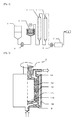
Fig. 1 is a diagram schematically illustrating an exemplary device for producing an acrylonitrile-based polymer solution that can be suitably used for a process for producing an acrylonitrile-based polymer solution of the invention. -
Fig. 2 is a diagram schematically illustrating an exemplary device (shearing device) for dispersing by shear force a mixture of an acrylonitrile-based polymer and a solvent. -
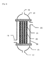
Fig. 3 is a diagram schematically illustrating an exemplary device for heating a mixture of an acrylonitrile-based polymer and a solvent or an acrylonitrile-based polymer solution. - According to the invention, a mixture of an acrylonitrile-based polymer and a solvent is supplied to a shearing device (in particular, a dispersion chamber of the device). The shearing device has a cylinder and a rotor that rotates inside the cylinder. The dispersion chamber is provided between an inner wall of the cylinder and an outer wall of the rotor. By rotating the rotor, shear force is applied to the mixture inside the dispersion chamber. By doing so, at least the polymer is dispersed and it is also possibly accompanied with dissolution of the polymer.
- According to the first mode of the process for producing an acrylonitrile-based polymer solution of the invention, shear force is applied to a mixture in a dispersion chamber and the obtained mixture is then heated to yield an acrylonitrile-based polymer solution.
- According to the second mode of the process for producing an acrylonitrile-based polymer solution of the invention, shear force is applied to a mixture in a dispersion chamber to yield an acrylonitrile-based polymer solution. In this case, heating is not performed after applying shear force.
- According to the first mode described above, that is, when the mixture is heated after being applied with shear force, the rotor is rotated under the following conditions represented by the formula I at the time of applying shear force:

- In the above, W1 is an electric power (kW) required for rotating the rotor at the time of applying shear force to the mixture. W2 is an electric power (kW) required for obtaining the same rotation number as the rotation number of the rotor at the time of obtaining W1 when, instead of the mixture, water is used in the same mass flow amount as the mixture. M is a mass flow amount (kg/h) of the acrylonitrile-based polymer supplied to the dispersion chamber at the time of obtaining W1.
- When shear force is applied to the mixture by rotating the rotor under the conditions at which the above W satisfies the formula I, it becomes easy for an acrylonitrile-based polymer and a solvent to get homogenously mixed. Accordingly, clogging of a filter hardly occurs, and therefore it is desirable.
- The above W represents an electric power obtained from the electric power (W1 - W2), which is obtained by subtracting W2 as an electric power at the time of using water (water in the same mass flow amount as the mixture for obtaining W1) with the same rotation number as the rotation number of having W1 from W1 as an electric power for rotating the rotor in the mixture, expressed in terms of a unit mass flow amount of the acrylonitrile-based polymer in the mixture present in a dispersion chamber of a shearing device. Namely, it can be said that W is a value of shear force applied to the mixture while it stays within a shearing device, but expressed in electric power.
- A system being applied with W2 is basically the same as a system being applied with W1 except that the same mass flow amount of water is used instead of the mixture (consequently, measured W1 and W2 are different from each other).
- According to the second mode described above, that is, when an acrylonitrile-based polymer solution is obtained by applying shear force to a mixture in a dispersion chamber (heating is not performed after applying shear force), the rotor is rotated under the following conditions represented by the formula II at the time of applying shear force:

In the above, W1, W2, and M are as defined in the above formula I. - According to the second mode described above, when shear force is applied to the mixture by rotating the rotor under the conditions at which the W satisfies the formula II, it becomes easy for an acrylonitrile-based polymer and a solvent to get homogenously mixed. Accordingly, clogging of a filter hardly occurs, and therefore it is desirable.
- With regard to the first and second modes described above, to satisfy the conditions of the formula I or the formula II, it is actually sufficient that the rotation number of the rotor is controlled.
- Hereinbelow, the embodiments for carrying out the invention are described in detail in view of the drawings. However,
Figs. 1, 2 and3 are all schematically described for easy explanation of the embodiments of the invention, and the invention is not limited at all to those configurations. - The device illustrated in
Fig. 1 is described. To the supply tank 1, a mixture of an acrylonitrile-based polymer and a solvent is supplied. By asupply pump 2, the mixture is supplied to ashearing device 3, in which the acrylonitrile-based polymer is dispersed (in general, at least part of the polymer is dissolved in addition to dispersion of the polymer). The liquid (mixture) discharged from the shearing device is sent to a heatingtype dissolving device 4, in which the polymer is dissolved by heating. After that, the mixture is cooled in acooling device 5 and pressurized by a spinningsupply pump 6, and then filtered by a filtering filter 7. The acrylonitrile-based polymer solution obtained from the device can be supplied to, as a dope for spinning, aspinneret 8 of a spinning device for obtaining an acrylonitrile-based fiber. The device is not a batch type but a flow type shearing device. - This device is suitable for performing the first mode of the process for producing an acrylonitrile-based polymer solution described above. For performing the second mode described above, heating should be performed by the heating
type dissolving device 4 of the device. Alternatively, by using a device having a configuration in which the heatingtype dissolving device 4 is removed from the device, the second mode can be performed. - According to the first mode for producing an acrylonitrile-based polymer solution, the upper limit of W at the time of applying shear force to a mixture of an acrylonitrile-based polymer solution and a solvent is preferably 4.00 kWh/kg or less. When it is 4.00 kWh/kg or less, it becomes easy to suppress an occurrence of gellation that is caused by increased temperature of the mixture by heating. The W is more preferably 2.70 kWh/kg or less. It is more preferably less than 1.60 kWh/kg.
- When the W is 1.60 kWh/kg or more, an acrylonitrile-based polymer solution can be obtained even without heating after a step of applying shear force (shear force applying step). However, when it is 4.00 kWh/kg or less, heating may be performed after the shear force applying step. Whether to perform heating after the shear force applying step can be suitably selected based on a composition of the mixture, or the like.
- Furthermore, with regard the second mode for producing an acrylonitrile-based polymer solution, that is, when heating by using a heating device is not performed, it is desirable to have the W of 1.60 kWh/kg or more and dissolve the polymer with heat generation caused by shear force while performing dispersion by shear force, because it becomes easy for the polymer to get homogenously mixed so that the filter is hardly clogged. The W is preferably 2.00 kWh/kg or more. Furthermore, from the viewpoint of preventing gellation caused by high temperature, the W is preferably 5.00 kWh/kg or less. It is more preferably 3.60 kWh/kg or less, and even more preferably 3.00 kWh/kg or less.
- From the viewpoint of preventing high temperature of the mixture based on heat generation caused by shear force, it is also possible that the mixture is cooled by adding a jacket for cooling the mixture to at least part of the shearing device (in particular, perimeter of a device).
- The temperature of the mixture at an exit of the dispersion chamber is preferably 40 to 115°C. When it is 40°C or higher, the polymer is slowly dissolved in a solvent so that it becomes easy to have homogeneous dissolving. Furthermore, when it is 115°C or lower, gelation of the dissolved mixture can be easily prevented. The exit temperature is more preferably 100°C or lower, and even more preferably 80°C or lower.
- Herein, the shearing device illustrated in
Fig. 2 is described. This device is a pin type mixer having acylinder 10 with a barrel shape. In the inside of thesame cylinder 10, arotor 9 with a column shape is installed such that it can rotate at high speed while its axial center line is in line with the axial center line of thecylinder 10. Each of therotor 9 and thecylinder 10 haspin members pin members dispersion chamber 14 is formed between the inner wall of thecylinder 10 and the outer wall of therotor 9. The outer shape of the rotor (excluding the pin member) has a rotating-body shape, and at least the inner wall of the cylinder (excluding the pin member) also has a rotating-body shape. - At the bottom center of the
cylinder 10, an inlet for supplying a mixture of the polymer and a solvent sent by the pump to the inside of thecylinder 10 is formed and also an outlet for the obtained polymer solution is formed on the top part of thesame cylinder 10. - In this device, the
flow paths cylinder 10 and therotor 9. By flowing heating or cooling fluid along those flow paths, it becomes easier to control the temperature of the mixture (liquid). However, it is not entirely necessary to use those flow paths. - With regard to the device, W1 is an electric power measured at the time of rotating the
rotor 9 with a certain rotation number when a mixture of an acrylonitrile-based polymer and a solvent is supplied to a dispersion chamber. W2 is an electric power measured in the same manner as W1 except that, instead of the mixture, water is used in the same mass flow amount as the mixture. M is a mass flow amount of the acrylonitrile-based polymer which is present in the mixture at the time of measuring W1. - According to this shearing device, shear force is applied to the mixture by rotating the barrel-shaped
rotor 9 having thepin member 12 while the mixture passes through the device and thus homogeneous mixing of an acrylonitrile-based polymer and a solvent is achieved. With regard to a change in the processing amount and viscosity, the target W can be obtained by modifying the rotation number of therotor 9. - As long as it allows an operation satisfying the conditions that are represented by the formula I or the formula II, a known device can be used as a shearing device.
- The shape of the shearing device is not limited as long as it can apply shear force to a fluid with high viscosity. Examples thereof include a kneader, an auger, a helical rotor, a screw extruder, a thermal processor, a pin mixer, a roll mixer, a tapered roll mixer, an internal mixer, a continuous mixer, a banburry mixer, a gear compounder, a meat mill, an attritor, and a sand grinder. Among them, from the viewpoint of having efficient application of shear force to the mixture, the pin mixer is preferable.
- According to the first mode, the time for the mixture to stay in a dispersion chamber of the shearing device (dwell time) is preferably 3 to 800 seconds. When the dwell time is 3 seconds or longer, it becomes easy to disperse the polymer homogeneously in a solvent by applying shear force to the mixture. The dwell time is preferably 10 seconds or longer, and more preferably 15 seconds or longer. Furthermore, when it is 800 seconds or shorter, the shear force applied to the mixture is not excessive so that an occurrence of gelation caused by heat generation can be easily suppressed. The dwell time is preferably 300 seconds or shorter, and more preferably 200 seconds or shorter.
- According to the second mode, the dwell time is preferably 600 to 1500 seconds. When the dwell time is 600 seconds or longer, it becomes easy to dissolve the polymer in a solvent by using shear heat by applying shear force to the mixture. Furthermore, when it is 1500 seconds or shorter, the shear force applied to the mixture is not excessive so that an occurrence of gelation caused by the heat generation can be easily suppressed. The dwell time is preferably 1000 seconds or shorter, and more preferably 800 seconds or shorter.
- When the shearing device is a pin type mixer, a distance between the tip of the pin and the wall facing the tip of the pin is preferably 2 mm or more but less than 5 mm. As for
Fig. 2 , a distance between the tip of thepin member 12, which is projectingly installed on an outer wall of the rotor, and an inner wall of thecylinder 10 is preferably 2 mm or more but less than 5 mm. Furthermore, a distance between the tip of thepin member 13, which is projectingly installed on an inner wall of the cylinder, and an outer wall of therotor 9 is 2 mm or more but less than 5 mm. When the distance is 2 mm or more, the pin member does not touch a wall surface even when there is mechanical vibration or eccentricity, and thus stable operation can be easily achieved. Furthermore, when the distance is less than 5 mm, it is easy to proceed with dissolving by generating shear force. - Furthermore, the axial direction distance between neighboring pin members (distance in rotational axis direction of a rotor, which is a distance in vertical direction in
Fig. 2 ) is preferably 2 mm to 10 mm when thepin member 13 projectingly installed on an inner peripheral surface of the cylinder and thepin member 12 projectingly installed on an outer peripheral surface of the rotor come nearest to each other. When the distance is 2 mm or more, the pin members are not in contact with each other even when there is mechanical vibration or eccentricity, and thus stable operation can be easily achieved. Furthermore, when the distance is 10 mm or less, it is easy to proceed with dissolving by generating shear force. - According to the first mode of the process for producing an acrylonitrile-based polymer solution, heating after the step of applying shear force can be performed by using a suitable heating device which enables heating to the temperature at which the acrylonitrile-based polymer is dissolved in a solvent. Examples of the heating device which may be used include a heat exchanger (a multi-tube type heat exchanger, a plate type heat exchanger, or the like) and a temperature control tank. For example, the heating can be performed by using a heating type dissolving device illustrated in
Fig. 3 . The device can be installed behind the shearing device. - With regard to the device illustrated in
Fig. 3 , a heating medium is supplied from theheating medium inlet 20 provided on thebody 23 and the heating medium is discharged from theheating medium exit 19. A liquid for heating (a mixture of an acrylonitrile-based polymer and a solvent) flows starting from theliquid inlet 17, passes through thetube 21 via the inletside channel cover 15, and is discharged from theliquid exit 18 via the exitside channel cover 16. The mixing element (static mixer) 22 is disposed inside the tube. Heat is applied from the heating medium to the liquid for heating the inside of the tube. Furthermore, as the liquid for heating is stirred by the mixer element, the polymer is dissolved. - With regard to the heating which is performed after the step of applying shear force, the mixture is preferably heated to 60°C to 150°C. When it is 60°C or higher, the acrylonitrile-based polymer is easily dissolved in a solvent. Furthermore, when it is 150°C or lower, gelation of an acrylonitrile-based polymer solution hardly occurs. The temperature is preferably 80°C to 140°C. More preferably, it is 90°C to 130°C. Particularly preferably, it is 100°C to 130°C.
- Furthermore, the heating time for the heating which is performed after the step of applying shear force is preferably 1 minute to 15 minutes. When it is 1 minute or longer, it becomes easy for a mixture of an acrylonitrile-based polymer to dissolve sufficiently. Furthermore, when it is 15 minutes or shorter, gelation can be easily prevented. It is more preferably 3 to 10 minutes.
- The acrylonitrile-based polymer is a polymer which contains acrylonitrile unit as a main constitutional unit. The ratio of the acrylonitrile unit in the acrylonitrile-based polymer is 80% by mass or more, for example. It is 92% by mass or more, and particularly 96% by mass or more. A monomer other than acrylonitrile constituting the acrylonitrile-based polymer can be suitably selected from a vinyl-based monomer which can copolymerize with acrylonitrile. Preferred examples thereof include a vinyl-based monomer which enhances hydrophilicity of the acrylonitrile-based polymer and a vinyl-based monomer which has an effect of promoting flame resistance.
- Examples of the monomer which enhances hydrophilicity of the acrylonitrile-based polymer include a vinyl compound having a hydrophilic functional group such as a carboxy group, a sulfo group, an amino group, an amide group, or a hydroxyl group.
- Examples of the monomer having a carboxy group include acrylic acid, methacrylic acid, itaconic acid, crotonic acid, citraconic acid, ethacrylic acid, maleic acid, and mesaconic acid. Among them, acrylic acid, methacrylic acid, and itaconic acid are preferable.
- Examples of the monomer having a sulfo group include allyl sulfonic acid, methallyl sulfonic acid, styrene sulfonic acid, 2-acrylamide-2-methylpropane sulfonic acid, vinyl sulfonic acid, and sulfoporpyl methacrylate. Among them, allyl sulflonic acid, methallyl sulfonic acid, styrene sulfonic acid, and 2-acrylamide-2-methylpropane sulfonic acid are preferable.
- Examples of the monomer having an amino group include dimethylaminoethyl methacrylate, diethylaminoethyl methacrylate, dimethylaminoethyl acrylate, diethylaminoethyl acrylate, tertiary butylaminoethyl methacrylate, allylamine, o-aminostyrene, and p-aminostyrene. Among them, dimethylaminoethyl methacrylate, diethylaminoethyl methacrylate, dimethylaminoethyl acrylate, and diethylaminoethyl acrylate are preferable.
- Preferred examples of the monomer having an amide group include acrylamide, methacrylamide, dimethyl acrylamide, and crotone amide.
- Examples of the monomer having a hydroxyl group include hydroxymethyl methacrylate, hydroxymethyl acrylate, 2-hydroxyethyl methacrylate, 2-hydroxyethyl acrylate, 3-hydroxypropyl methacrylate, 3-hydroxypropyl acrylate, 2-hydroxypropyl methacrylate, and 2-hydroxypropyl acrylate.
- According to blending of such monomers, the acrylonitrile-based polymer can have improved hydrophilicity. With the improved hydrophilicity, a precursor fiber obtained from the polymer can have improved density so that an occurrence of a micro void on a surface layer part can be suppressed.
- The aforementioned monomer may be used either singly or in suitable combination of two or more types. The blending amount of the monomer for improving the hydrophilicity of an acrylonitrile-based polymer is preferably 0.5 to 10.0% by mass, and more preferably 0.5 to 4.0% by mass in the acrylonitrile-based polymer.
- Examples of the monomer having an effect of promoting flame resistance include acrylic acid, methacrylic acid, ethacrylic acid, itaconic acid, crotonic acid, citraconic acid, maleic acid, mesaconic acid, a lower alkyl ester, an alkali metal salt, an ammonium salt of those acids, acrylamide, and methacrylamide.
- Among them, from the viewpoint of obtaining the effect of higher promoting flame resistance with a small blending amount, a monomer having a carboxy group is preferred. In particular, a vinyl-based monomer like acrylic acid, methacrylic acid, and itaconic acid is more preferred.
- According to blending of such monomers, the time for the flame resistance treatment which is described below can be shortened, and thus production cost can be reduced.
- The aforementioned monomer can be used either singly or in suitable combination of two or more types. The blending amount of the monomer having an effect of promoting flame resistance is preferably 0.5 to 10.0% by mass, and more preferably 0.5 to 4.0% by mass in the acrylonitrile-based polymer.
- Any solvent can be used as long as it is capable of dissolving an acrylonitrile-based polymer. Examples thereof include an organic solvent such as dimethyl acetamide, dimethyl sulfoxide, and dimethyl formamide, and an aqueous solution of an inorganic compound such as zinc chloride and sodium thiocyanate. Dimethyl acetamide, dimethyl sulfoxide, and dimethyl formamide are preferable in that they allow obtainment of a dense precursor fiber of an acrylonitrile-based carbon fiber.
- The mixture of acrylonitrile-based polymer obtained by using a shearing device contains a little amount of poor mixing products and the acrylonitrile-based polymer is homogeneously mixed therein. Thus, by dissolving the mixture, a homogeneous acrylonitrile-based polymer solution having a little amount of undissolved products and irregularities can be obtained.
- The acrylonitrile-based polymer solution obtained by the invention contains a little amount of undissolved products and the acrylonitrile-based polymer can be homogeneously dissolved in a solvent. Accordingly, an acrylonitrile-based fiber (a precursor fiber of a carbon fiber) can be efficiently produced. Further, the acrylonitrile-based fiber obtained therefrom also has a little amount of irregularities in its length direction or in staple fibers, and thus it has a high quality. Examples of the spinning method include a known method like a wet spinning method and a dry and wet spinning method.
- When thus-obtained acrylonitrile-based fiber is calcined according to a known method, a carbon fiber can be obtained.
- According to the process of the invention, an acrylonitrile-based polymer is homogeneously and also sufficiently dissolved in a solvent so that clogging of a filter or a spinning nozzle hardly occurs. As a result, it is possible to produce an acrylonitrile-based polymer solution which is excellent in terms of cost.
- Hereinbelow, the invention is described in detail with referring to Examples and Comparative Examples, but the invention is not limited to them. Meanwhile, various tests of Examples and Comparative Examples given below are as described in the followings.
- While being maintained at 60°C, the produced acrylonitrile-based polymer solution was supplied in a predetermined amount at a flow amount of 1.6 g/minute to a stainless steel filter for fiber calcination which has a filtering area of 28 cm2 and a mesh of 5 µm (model number NF2M-05S, manufactured by Nippon Seisen Co., Ltd.). After having the acrylonitrile-based polymer solution pass through the filter, pressure difference as a difference in pressure before and after filtering at the time of having integrated pass-through polymer amount per unit area of 100 kg/m2 and 1000 kg/m2 was measured. With regard to the level of pressure increase, the pressure difference at the time of having integrated pass-through polymer amount of 100 kg/m2 is subtracted from the pressure difference at the time of having integrated pass-through polymer amount of 1000 kg/m2 and the resultant value is converted in terms of the mass of the integrated pass-through polymer which passes through a unit filtering area, and then used for comparison.
- For the measurement of the electric power W1 and W2, a power meter (model number: MODEL6300, manufactured by KYORITSU ELECTRICAL INSTRUMENTS WORKS, LTD.) was used. The power meter was attached onto a connection end located on the primary side of an inverter for controlling a motor for rotating the rotor of a shearing device. W1 is an average value obtained by measuring for 10 seconds the electric power (kW) required for rotating the rotor at the time of applying shear force to the mixture, and W2 is an average value obtained by measuring for 10 seconds the electric power (kW) required for obtaining the same rotation number as the rotation number of the rotor at the time of obtaining W1 when water is used in the same mass flow amount as the mixture instead of the mixture. The index W is a value obtained by dividing the value resulting from subtracting W2 from W1 by the mass flow amount M of the acrylonitrile-based polymer in the mixture which is present in a dispersion chamber of a shearing device (at the time of obtaining W1).
- An acrylonitrile-based polymer consisting of 96% by mass of an acrylonitrile monomer unit (AN), 1% by mass of a methacrylic acid monomer unit (MAA), and 3% by mass of an acrylamide monomer unit (AAm), and dimethyl acetamide were prepared as an acrylonitrile-based polymer and a solvent, respectively.
- The acrylonitrile-based polymer was added in small portions to a tank in which dimethyl acetamide is under stirring, and then it was mixed therein.
- The mixture (polymer concentration of 21.2% by mass, and temperature of 10°C) was supplied at 450 g/minute to a shearing device illustrated in
Fig. 2 by using a metering pump. The mixture discharged from the shearing device was supplied to a heating type dissolving device illustrated inFig. 3 . In that case, the index W for rotating the rotor by a shearing device was 0.28 kWh/kg and the dwell time of the mixture in the dispersion chamber was 2.4 minutes. - The temperature of the mixture discharged from the shearing device was set at 100°C or lower. To have such temperature, water was allowed to flow into the jacket of the shearing device so that the temperature of the mixture can be controlled. By doing so, the acrylonitrile-based polymer was dissolved in the solvent and an acrylonitrile-based polymer solution (dope for spinning) was obtained.
- In the
dispersion chamber 14 formed between the cylinder and the rotor of the shearing device, the distance between the inner wall of the cylinder and the outer wall of the rotor is 16.5 mm, and square column pin members having a projecting length of 13.5 mm from the wall, a height of 8 mm, and a width of 8 mm were arranged in 12 rows and 11 columns on an outer peripheral surface of the rotor and in 12 rows and 12 columns on an inner peripheral surface of the cylinder. The distance between the tip of the pin member added on the cylinder and the outer wall of the rotor was 3.0 mm and the distance between the tip of the pin member added on the rotor and the inner wall of the cylinder was 3.0 mm. The axial direction distance between neighboring pin members was 3 mm when the pin member projectingly installed on an inner peripheral surface of the cylinder and the pin member projectingly installed on an outer peripheral surface of the rotor come nearest to each other. As described herein, the "row" indicates the number of pin members in peripheral direction and the "column" indicates the number of pin members in axial direction of the rotor. - The heating type dissolving device is a multi-tube type heat exchanger which has an inner diameter of 12.7 mm, a length of 600 mm, and 12 tubes. The mixture of an acrylonitrile-based polymer and a solvent was applied with shear force by a shearing device while being cooled by water flowing through the flow path for heating or cooling fluid (11a and 11b), and then the mixture of an acrylonitrile-based polymer was heated to the temperature at an exit of the heat exchanger of 110°C by using a heating type dissolving device for dissolving, it was cooled to 60°C. The obtained acrylonitrile-based polymer mixture solution was subjected to a filtering pressure increase test and the results are as described in Table 1.
- An acrylonitrile-based polymer solution was obtained according to the same operation as Example 1 except that the index W for rotating the rotor and the dwell time in the shearing device were changed to those described in Table 1.
- An acrylonitrile-based polymer solution was obtained according to the same operation as Example 1 except that the index W for rotating the rotor and the dwell time in the shearing device were changed to those described in Table 1, and the heat exchanger was not used.
- An acrylonitrile-based polymer consisting of 98% by mass of an acrylonitrile monomer unit and 2% by mass of a methacrylic acid monomer unit, and dimethyl acetamide were prepared as an acrylonitrile-based polymer and a solvent, respectively.
- The mixture (polymer concentration of 23.2% by mass, and temperature of 10°C) was supplied at 440 g/minute to a shearing device illustrated in
Fig. 2 by using a metering pump. The mixture discharged from the shearing device was supplied to a heating type dissolving device illustrated inFig. 3 . In that case, the index W for rotating the rotor by a shearing device was 0.22 kWh/kg. - An acrylonitrile-based polymer solution was obtained in the same manner as Example 1 except those described above and then the obtained solution was subjected to a filtering pressure increase test.
- An acrylonitrile-based polymer solution was obtained according to the same operation as Example 9 except that the index W for rotating the rotor and the dwell time in the shearing device were changed to those described in Table 1.
- An acrylonitrile-based polymer solution was obtained in the same manner as Example 1 except that the shearing device was not used and, by only using a heating type dissolving device (a multi-tube type heat exchanger), dissolving was carried out with 6 minutes of the dwell time in the exchanger and 110°C of the temperature of the mixture of an acrylonitrile-based polymer at an exit of the heat exchanger followed by cooling to temperature of 60°C.
- An acrylonitrile-based polymer solution was obtained according to the same operation as Example 1 except that the index W for rotating the rotor and the dwell time in the shearing device were changed to those described in Table 1, and the heating type dissolving device was not used.
- An acrylonitrile-based polymer solution was obtained in the same manner as Example 9 except that the shearing device was not used and, by only using a heating type dissolving device (a multi-tube type heat exchanger), dissolving was carried out with 6 minutes of the dwell time in the heat exchanger and 110°C of the temperature of the mixture of an acrylonitrile-based polymer at an exit of the heat exchanger followed by cooling to temperature of 60°C.
- An acrylonitrile-based polymer solution was obtained according to the same operation as Example 9 except that the index W for rotating the rotor and the dwell time in the shearing device were changed to those described in Table 1.
- The results of the filtering pressure increase test for the above Examples and Comparative Examples are shown in Table 1. In the table, the dwell time in the shearing device indicates the time of mixture dwelling within a dispersion chamber of the shearing device. The temperature at an exit of the shearing device indicates the temperature of the mixture at an exit of the dispersion chamber of the shearing device.
- [Table 1]
Table 1 Index W Dwell time in shearing device Temperature at exit of shearing device Dwell time in heating type dissolving device Filtering pressure increase test Component ratio in polymer Remarks kWh/kg Minutes °C Minutes Pa/(kg/m2) AN/MAA/AAm Example 1 0.28 2.4 70 6 72 96/1/3 Example 2 0.31 2.7 69 6 114 96/1/3 Example 3 1.76 12.2 75 6 188 96/1/3 Example 4 1.61 12.2 71 Not used 188 96/1/3 Example 5 1.68 12.2 75 Not used 149 96/1/3 Example 6 1.70 12.2 74 Not used 163 96/1/3 Example 7 2.27 12.2 74 Not used 121 96/1/3 Example 8 3.27 24.3 91 Not used 203 96/1/3 Example 9 0.22 2.8 56 6 148 98/2/0 Example 10 0.31 0.9 76 6 168 98/2/0 Example 11 0.36 1.4 76 6 92 98/2/0 Example 12 0.47 2.8 69 6 111 98/2/0 Example 13 0.64 2.8 86 6 107 98/2/0 Comparative Example 1 Not used 6 229 96/1/3 Shearing device was not used Comparative Example 2 0.31 2.7 72 Not used 457 96/1/3 Outside the index range Comparative Example 3 1.28 12.2 88 Not used 295 96/1/3 Outside the index range Comparative Example 4 1.44 12.2 76 Not used 299 96/1/3 Outside the index range Comparative Example 5 Not used 6 439 98/2/0 Shearing device was not used Comparative Example 6 0.09 2.8 20 6 466 98/2/0 Outside the index range Comparative Example 7 0.11 1.6 28 6 516 98/2/0 Outside the index range - As it is obvious from the above examples and Comparative Examples, with the process of the invention, an acrylonitrile-based polymer can be dissolved homogeneously and sufficiently dissolved in a solvent by using a shearing device and a heating type dissolving device (the first mode). In particular, with the index W of 0.12 to 4.00 kWh/kg for rotating the rotor, a high effect of improving the filtering property, that is, effect of enhancing dissolving property, is obtained.
- Further, when only a shearing device is used (the second mode), a good filtering property is included if the index W for rotating the rotor is in the range of 1.60 to 5.00 kWh/kg.
-
- 1
- Supply tank
- 2
- Supply pump
- 3
- Shearing device
- 4
- Heating type dissolving device
- 5
- Cooling device
- 6
- Spinning supply pump
- 7
- Filtering filter
- 8
- Spinneret
- 9
- Rotor
- 10
- Cylinder
- 11a
- Flow path for heating or cooling fluid
- 11b
- Flow path for heating or cooling fluid
- 12
- Pin member (on outer peripheral surface of rotor)
- 13
- Pin member (on inner peripheral surface of cylinder)
- 14
- Dispersion chamber
- 15
- Channel cover on inlet side
- 16
- Channel cover on exit side
- 17
- Liquid inlet
- 18
- Liquid outlet
- 19
- Exit for heating medium
- 20
- Inlet for heating medium
- 21
- Tube
- 22
- Mixer element
- 23
- Body
Claims (17)
- A process for producing an acrylonitrile-based polymer solution comprising supplying a mixture of an acrylonitrile-based polymer and a solvent to a dispersion chamber of a shearing device having a cylinder and a rotor that rotates inside the cylinder, rotating the rotor under the following conditions to apply shear force to the mixture, and thereafter heating the obtained mixture to obtain an acrylonitrile-based polymer solution:

in which W1 is an electric power (kW) required for rotating the rotor at the time of applying shear force to the mixture; W2 is an electric power (kW) required for obtaining the same rotation number as the rotation number of the rotor at the time of obtaining W1 when, instead of the mixture, water is used in the same mass flow amount as the mixture; and M is a mass flow amount (kg/h) of the acrylonitrile-based polymer supplied to the dispersion chamber at the time of obtaining W1. - The process for producing an acrylonitrile-based polymer solution according to claim 1, wherein the W is 4.00 kWh/kg or less.
- The process for producing an acrylonitrile-based polymer solution according to claim 1, wherein the W is less than 1.60 kWh/kg.
- The process for producing an acrylonitrile-based polymer solution according to any one of claims 1 to 3, wherein the mixture is heated at 100 to 130°C during the heating.
- The process for producing an acrylonitrile-based polymer solution according to any one of claims 1 to 4, wherein, for the heating, the heating is performed by using at least one means selected from a heat exchanger and a temperature control tank and a pin type mixer is used as a shearing device.
- A process for producing an acrylonitrile-based polymer solution comprising supplying a mixture of an acrylonitrile-based polymer and a solvent to a dispersion chamber of a shearing device having a cylinder and a rotor that rotates inside the cylinder and rotating the rotor under the following conditions to apply shear force to the mixture for obtaining an acrylonitrile-based polymer solution:

in which W1 is an electric power (kW) required for rotating the rotor at the time of applying shear force to the mixture; W2 is an electric power (kW) required for obtaining the same rotation number as the rotation number of the rotor at the time of obtaining W1 when, instead of the mixture, water is used in the same mass flow amount as the mixture; and M is a mass flow amount (kg/h) of the acrylonitrile-based polymer supplied to the dispersion chamber at the time of obtaining W1. - The process for producing an acrylonitrile-based polymer solution according to claim 6, wherein the W is 5.00 kWh/kg or less.
- The process for producing an acrylonitrile-based polymer solution according to any one of claims 1 to 7, wherein the dwell time of the mixture in the dispersion chamber of the shearing device is 3 seconds to 1500 seconds.
- The process for producing an acrylonitrile-based polymer solution according to any one of claims 1 to 8, wherein the temperature of the mixture at an exit of the dispersion chamber is 40°C to 115°C.
- The process for producing an acrylonitrile-based polymer solution according to any one of claims 1 to 9, wherein the shearing device is a pin type mixer having pin members projectingly installed on positions of an inner wall of the cylinder and an outer wall of the rotor, each of the positions not being in contact with each other, and a distance between the tip of the pin member projectingly installed on the outer wall of the rotor and the inner wall of the cylinder is 2 mm or more but less than 5 mm.
- The process for producing an acrylonitrile-based polymer solution according to any one of claims 1 to 10, wherein the shearing device is a pin type mixer having pin members projectingly installed on positions of an inner wall of the cylinder and an outer wall of the rotor, each of the positions not being in contact with each other, and a distance between the tip of the pin member projectingly installed on the inner wall of the cylinder and the outer wall of the rotor is 2 mm or more but less than 5 mm.
- The process for producing an acrylonitrile-based polymer solution according to any one of claims 1 to 11, wherein the axial direction distance between neighboring pin members is 2 mm to 10 mm when the pin member projectingly installed on the inner wall of the cylinder and the pin member projectingly installed on the outer wall of the rotor come nearest to each other.
- A shearing device for an acrylonitrile-based polymer solution, the shearing device having a cylinder and a rotor that rotates inside the cylinder in which pin members are projectingly installed on positions of an inner wall of the cylinder and an outer wall of the rotor, each of the positions not being in contact with each other, and a distance between the tip of the pin member projectingly installed on the outer wall of the rotor and the inner wall of the cylinder is 2 mm or more but less than 5 mm.
- The shearing device for an acrylonitrile-based polymer solution according to claim 13, wherein the distance between the tip of the pin member projectingly installed on the inner wall of the cylinder and the outer wall of the rotor is 2 mm or more but less than 5 mm.
- The shearing device for an acrylonitrile-based polymer solution according to claim 13 or 14, wherein the axial direction distance between neighboring pin members of the pin member projectingly installed on the inner wall of the cylinder and the pin member projectingly installed on the outer wall of the rotor is 2 mm to 10 mm.
- A process for producing an acrylonitrile-based fiber by spinning an acrylonitrile-based polymer solution produced by the production process according to any one of claims 1 to 12 to obtain an acrylonitrile-based fiber.
- A process for producing a carbon fiber by calcining an acrylonitrile-based fiber produced by the production process according to claim 16 to obtain a carbon fiber.
Applications Claiming Priority (2)
| Application Number | Priority Date | Filing Date | Title |
|---|---|---|---|
| JP2012196407 | 2012-09-06 | ||
| PCT/JP2013/073660 WO2014038539A1 (en) | 2012-09-06 | 2013-09-03 | Process for producing acrylonitrile-based polymer solution, shearing device, process for producing acrylonitrile-based fiber, and process for producing carbon fiber |
Publications (2)
| Publication Number | Publication Date |
|---|---|
| EP2894188A1 true EP2894188A1 (en) | 2015-07-15 |
| EP2894188A4 EP2894188A4 (en) | 2015-09-16 |
Family
ID=50237148
Family Applications (1)
| Application Number | Title | Priority Date | Filing Date |
|---|---|---|---|
| EP13835951.8A Withdrawn EP2894188A4 (en) | 2012-09-06 | 2013-09-03 | ACRYLONITRILE POLYMER SOLUTION, SHEAR DEVICE, PROCESS FOR PRODUCING ACRYLONITRILE FIBER, AND PROCESS FOR PRODUCING CARBON FIBER |
Country Status (8)
| Country | Link |
|---|---|
| US (1) | US20150259480A1 (en) |
| EP (1) | EP2894188A4 (en) |
| JP (1) | JP5692407B2 (en) |
| KR (1) | KR101728253B1 (en) |
| CN (1) | CN104619751A (en) |
| MX (1) | MX2015002970A (en) |
| TW (1) | TWI499620B (en) |
| WO (1) | WO2014038539A1 (en) |
Cited By (2)
| Publication number | Priority date | Publication date | Assignee | Title |
|---|---|---|---|---|
| WO2020205562A1 (en) | 2019-03-29 | 2020-10-08 | Cytec Industries, Inc. | Process for the production of homogeneous solutions of polyacrylonitrile-based polymer |
| GB2613604A (en) * | 2021-12-08 | 2023-06-14 | Bevo Biotehnoloske Resitve D O O | Method and apparatus for continuous production of a structured protein product |
Families Citing this family (3)
| Publication number | Priority date | Publication date | Assignee | Title |
|---|---|---|---|---|
| ES2547755B1 (en) | 2015-06-25 | 2016-06-16 | Manuel Torres Martínez | Extrusion head for filament generation, installation and extrusion procedure using said extrusion head |
| WO2017186567A1 (en) * | 2016-04-26 | 2017-11-02 | Basf Se | A process and apparatus for producing an aqueous polymer solution |
| CN108854808A (en) * | 2018-07-04 | 2018-11-23 | 刘伟 | A kind of complex phosphate fertilizer mashing mechanism |
Family Cites Families (11)
| Publication number | Priority date | Publication date | Assignee | Title |
|---|---|---|---|---|
| US3287307A (en) * | 1965-03-29 | 1966-11-22 | Toho Rayon Kk | Method for preparation of the solution of acrylonitrile polymer |
| DE3313710A1 (en) * | 1983-04-15 | 1984-10-18 | Bayer Ag, 5090 Leverkusen | STIRRING DEVICE |
| JPH0394931U (en) * | 1990-01-08 | 1991-09-27 | ||
| JPH058219A (en) * | 1991-07-02 | 1993-01-19 | Kanegafuchi Chem Ind Co Ltd | Method for preparing polymer solution |
| JPH08318527A (en) * | 1995-05-26 | 1996-12-03 | Mitsui Toatsu Chem Inc | Improved distribution type dispersion device and resin dispersion method using the same |
| JP2001340741A (en) | 2000-06-02 | 2001-12-11 | Kanegafuchi Chem Ind Co Ltd | Continuous mixing device |
| JP4723710B2 (en) * | 2000-08-04 | 2011-07-13 | 三菱レイヨン株式会社 | Method for producing acrylonitrile-based spinning dope, method for producing acrylonitrile-based fiber, and method for producing carbon fiber |
| CN102046676B (en) * | 2008-05-30 | 2015-07-22 | 三菱丽阳株式会社 | Acrylonitrile copolymer and method for manufacturing the same, and acrylonitrile copolymer solution and polyacrylonitrile precursor fiber for carbon fiber and method for manufacturing the same |
| US8637155B2 (en) * | 2010-06-07 | 2014-01-28 | Dow Global Technologies Llc | Process for preparing stable dispersions of starch particles |
| EP2738292B1 (en) * | 2011-07-28 | 2019-10-09 | Mitsubishi Chemical Corporation | Flame-retardant heat treatment furnace |
| JP2013119202A (en) | 2011-12-07 | 2013-06-17 | Mitsubishi Rayon Co Ltd | Apparatus for manufacturing polymer mixed solution, method of manufacturing acrylonitrile based polymer mixed solution using the apparatus, method of manufacturing acrylonitrile based polymer solution, and method of manufacturing carbon fiber precursor acrylonitrile based fiber |
-
2013
- 2013-09-03 KR KR1020157005815A patent/KR101728253B1/en not_active Expired - Fee Related
- 2013-09-03 EP EP13835951.8A patent/EP2894188A4/en not_active Withdrawn
- 2013-09-03 CN CN201380046285.6A patent/CN104619751A/en active Pending
- 2013-09-03 US US14/425,913 patent/US20150259480A1/en not_active Abandoned
- 2013-09-03 JP JP2013541905A patent/JP5692407B2/en not_active Expired - Fee Related
- 2013-09-03 WO PCT/JP2013/073660 patent/WO2014038539A1/en not_active Ceased
- 2013-09-03 MX MX2015002970A patent/MX2015002970A/en unknown
- 2013-09-04 TW TW102131746A patent/TWI499620B/en active
Cited By (4)
| Publication number | Priority date | Publication date | Assignee | Title |
|---|---|---|---|---|
| WO2020205562A1 (en) | 2019-03-29 | 2020-10-08 | Cytec Industries, Inc. | Process for the production of homogeneous solutions of polyacrylonitrile-based polymer |
| AU2020256105B2 (en) * | 2019-03-29 | 2025-04-24 | Cytec Industries, Inc. | Process for the production of homogeneous solutions of polyacrylonitrile-based polymer |
| US12331170B2 (en) | 2019-03-29 | 2025-06-17 | Cytec Industries Inc. | Process for the production of homogeneous solutions of polyacrylonitrile-based polymer |
| GB2613604A (en) * | 2021-12-08 | 2023-06-14 | Bevo Biotehnoloske Resitve D O O | Method and apparatus for continuous production of a structured protein product |
Also Published As
| Publication number | Publication date |
|---|---|
| CN104619751A (en) | 2015-05-13 |
| JP5692407B2 (en) | 2015-04-01 |
| WO2014038539A1 (en) | 2014-03-13 |
| JPWO2014038539A1 (en) | 2016-08-08 |
| US20150259480A1 (en) | 2015-09-17 |
| KR20150041065A (en) | 2015-04-15 |
| MX2015002970A (en) | 2015-06-02 |
| TWI499620B (en) | 2015-09-11 |
| EP2894188A4 (en) | 2015-09-16 |
| KR101728253B1 (en) | 2017-04-18 |
| TW201420645A (en) | 2014-06-01 |
Similar Documents
| Publication | Publication Date | Title |
|---|---|---|
| US20150259480A1 (en) | Process for producing acrylonitrile-based polymer solution, shearing device, process for producing acrylonitrile-based fiber, and process for producing carbon fiber | |
| EP2566609B1 (en) | Emulsification device for continuously producing emulsions and/or dispersions | |
| JP6460801B2 (en) | Acrylic fiber manufacturing method | |
| Cruz et al. | Effect of operating conditions on batch and continuous paracetamol crystallization in an oscillatory flow mesoreactor | |
| RU2473721C2 (en) | Method and apparatus for manufacturing spinning solution for production of polymeric fiber | |
| US20190016867A1 (en) | Particulate polyamide, and method for preparing the particulate polyamide | |
| KR101777463B1 (en) | Method for preparing resin powders and integral floculator for the same | |
| EP3012019B1 (en) | Particle production device and particle production method using same | |
| CN115990441A (en) | A preparation system and preparation method of polyvinyl alcohol embolization microspheres with uniform particle size | |
| KR20170011214A (en) | Continuous manufacturing system of nano-porous silica, and thereof method | |
| JP2013119202A (en) | Apparatus for manufacturing polymer mixed solution, method of manufacturing acrylonitrile based polymer mixed solution using the apparatus, method of manufacturing acrylonitrile based polymer solution, and method of manufacturing carbon fiber precursor acrylonitrile based fiber | |
| CN116943558A (en) | Preparation process of composite nano oil displacement agent | |
| JP7647747B2 (en) | Apparatus and method for producing layered zirconium phosphate | |
| JP2022527107A (en) | Method for Producing a Uniform Solution of Polyacrylonitrile Polymer | |
| JP6658564B2 (en) | Equipment for producing ultrafine particles and porous precursors | |
| CN217189529U (en) | Horizontal reactor | |
| CN203794824U (en) | Production system capable of continuously producing copolymerized antistatic cationic polyester | |
| CN117619242A (en) | Microsphere preparation feed assembly, homogenizer and microsphere preparation method | |
| CN209155636U (en) | A kind of homogeneous dispersing apparatus of anionic surfactant | |
| EP3230346B1 (en) | Size reduction of ethylcellulose polymer particles | |
| CN118932502A (en) | A device and method for stabilizing high-solid-content and low-viscosity spinning solution | |
| Winstone | Production of catalyst supports by twin screw extrusion of pastes |
Legal Events
| Date | Code | Title | Description |
|---|---|---|---|
| PUAI | Public reference made under article 153(3) epc to a published international application that has entered the european phase |
Free format text: ORIGINAL CODE: 0009012 |
|
| 17P | Request for examination filed |
Effective date: 20150220 |
|
| AK | Designated contracting states |
Kind code of ref document: A1 Designated state(s): AL AT BE BG CH CY CZ DE DK EE ES FI FR GB GR HR HU IE IS IT LI LT LU LV MC MK MT NL NO PL PT RO RS SE SI SK SM TR |
|
| AX | Request for extension of the european patent |
Extension state: BA ME |
|
| RA4 | Supplementary search report drawn up and despatched (corrected) |
Effective date: 20150814 |
|
| RIC1 | Information provided on ipc code assigned before grant |
Ipc: B01F 1/00 20060101ALI20150810BHEP Ipc: B01F 3/12 20060101ALI20150810BHEP Ipc: B01F 7/00 20060101ALI20150810BHEP Ipc: B01F 7/16 20060101ALI20150810BHEP Ipc: B01F 15/06 20060101ALI20150810BHEP Ipc: C08J 3/09 20060101AFI20150810BHEP Ipc: D01D 1/02 20060101ALI20150810BHEP Ipc: D01F 6/18 20060101ALI20150810BHEP Ipc: D01F 9/22 20060101ALI20150810BHEP |
|
| DAX | Request for extension of the european patent (deleted) | ||
| RAP1 | Party data changed (applicant data changed or rights of an application transferred) |
Owner name: MITSUBISHI CHEMICAL CORPORATION |
|
| RAP1 | Party data changed (applicant data changed or rights of an application transferred) |
Owner name: MITSUBISHI CHEMICAL CORPORATION |
|
| STAA | Information on the status of an ep patent application or granted ep patent |
Free format text: STATUS: THE APPLICATION HAS BEEN WITHDRAWN |
|
| 18W | Application withdrawn |
Effective date: 20171201 |